Article

Removing Ice from Frozen Structures Using Bubble Pulsation Energy

1
College of Ocean Science and Engineering, Shanghai Maritime University, Shanghai 201306, China
2
College of Shipbuilding Engineering, Harbin Engineering University, Harbin 150001, China
*
Author to whom correspondence should be addressed.
J. Mar. Sci. Eng. 2024, 12(12), 2211; https://doi.org/10.3390/jmse12122211
Submission received: 10 October 2024 / Revised: 18 November 2024 / Accepted: 20 November 2024 / Published: 2 December 2024

Abstract

:
Icing poses significant threats to the safety and reliability of structures in cold regions, thus prompting researchers to explore deicing methods. This paper establishes a bubble deicing system and investigates the utilization of bubble pulsation energy for removing ice from frozen structures. Traditional deicing methods suffer from issues such as high energy consumption, severe environmental pollution, and secondary icing. To address these challenges and advance the development of deicing technology, harnessing the substantial energy generated by bubble pulsation can be employed for effective deicing purposes. Through experimental analysis, this study successfully demonstrates the feasibility of employing cavitation for deicing applications. Several experimental cases are conducted to elucidate the mechanism behind bubble-energy-based deicing, varying parameters including the distance between bubbles and targets as well as ice sheet thickness within a range of 5~35 mm. The findings indicate that bubbles can effectively facilitate deicing processes. Further exploration is required to fully understand the potential of bubble deicing technology and its prospects in engineering applications.

1. Introduction

The occurrence of icing is inevitable for structures operating in cold regions. Icing, which compromises the stability and reliability of these structures, significantly impairs engine performance and disrupts radio and radar signal reception. In the field of aeronautical engineering [1,2], the accumulation of ice on aircraft structures such as the tails, wings, and engine components can substantially diminish maximum lift capacity [3,4], Moreover, it increases drag and poses potential threats to aircraft safety in certain cases [5,6]. In the field of ocean engineering, the icing of polar ship structures and polar offshore platforms affects the seaworthiness of ships and the stability of offshore platforms. Particularly for polar ships with tall superstructures, icing may lead to ship overturning due to increases in the center of gravity and ship resistance caused by ice accumulation. The icing on the wires, cables, radar equipment, and other radio equipment aboard ships and offshore platforms affects communication signal reception, additionally increasing navigation difficulties when encountering icy areas or grounding incidents. Icing also affects the normal operation of winches, valves, cranes, and other equipment [7,8], thus posing a threat to worker safety [9,10]. Therefore, the continuous use of antifreezing and deicing technology is essential.
Generally, traditional deicing technology can be categorized into active and passive methods based on the approach used. Active methods typically require significant amounts of energy and resources from external sources such as blown-up sleeves that are used on certain commercial aircraft, mechanical energy, electric heating, or infrared radiation to remove ice. In contrast, passive methods rely on the paint itself to prevent ice formation and work in conjunction with wind [11,12]. The current deicing techniques commonly employed include chemical deicing, electric heating deicing, and electric pulse deicing, which require energy consumption and rely on external forces such as gravity. The deicing methods summarized by Xie et al. [13,14] include manual deicing, electric deicing, high-speed heat flow deicing, infrared deicing, ultrasonic deicing [15,16], chemical deicing [17,18], sacrificial coating deicing [19], and super-hydrophobic coating deicing methods [20,21,22]. The advantages, disadvantages, and applications of the current deicing techniques are summarized as follows: In the method involving electric heating for ice removal [23,24], resistance wires or other electric heating devices [25,26] are utilized as the heat source to melt and remove the ice layer. This process involves converting electrical energy from a generator into heat; its advantages lie in its quick and convenient nature. However, there is a drawback in terms of energy loss during conversion, which may lead to secondary icing. Electric deicing is commonly employed for removing ice from antennas, portholes, and other facilities. The high-speed heat flow deicing method [27,28] utilizes high-temperature and high-pressure water vapor to effectively melt the ice layer, with the added advantage of being able to recycle the generated heat energy through engines, boilers, and other equipment. However, it is important to note that this method has limitations when dealing with certain icing materials [29], as well as heat-sensitive materials [30,31] and brittle materials.The infrared deicing method involves irradiating the ice layer with specific wavelengths of infrared rays [32,33]. This allows for the targeted absorption of energy by the material in order to melt the ice layer without causing damage to any underlying coating or surface. It should be noted that secondary icing can still occur despite successfully melting the initial ice layer. The ultrasonic-guided deicing method operates on the principle of utilizing vibrations from ultrasonic guided waves to generate shear forces on both the surface of the ice and its surrounding structure. By surpassing the adhesion strength between these surfaces, effective deicing can be achieved. The ultrasonic-wave-guided deicing technique [34,35] overcomes the drawbacks of the high energy consumption and secondary icing associated with thermal deicing methods. However, its applicability is limited to structures such as plates, pipes, and chemical systems. Material deicing methods are commonly employed for snow-covered roads [36,37], where chemical products like calcium chloride and urea are sprayed or applied to melt the ice. Nevertheless, these approaches cause equipment corrosion and environmental pollution. Hydrophobic coating methods have a disadvantage in terms of inferior durability and stability compared to water-wettable coatings. Despite numerous efforts made to improve deicing techniques, low-energy-consumption and environmentally safe solutions are still required. Therefore, there is a need to develop novel deicing methods that utilize alternative energy sources for removing ice from frozen structures.
Bubbles are widely prevalent in nature and can be produced easily through various means [38,39]. The rapid generation of large-scale bubbles yields a greater power than anticipated. This energy is primarily attributed to the high-speed jet produced during the breakup process, which possesses significant destructive capabilities. Zhang et al. [40,41] introduced the groundbreaking concept of bubble-induced ice fracture. Studies [40,42] confirmed that bubbles can effectively break ice [43,44]. Moreover, employing a bubble generator [4] can prevent water around docked ships from freezing during winter. Various methods exist for generating highly pulsating bubbles, including electric-spark- and laser-induced bubbling phenomena. Two primary experimental approaches have been employed for bubble generation using electric sparks, namely, high-voltage ignition [45,46] and low-voltage ignition [47,48]. Both electrodes are connected to the charging capacitor’s two ends, and the system is short-circuited in water. The advantages of using EDM bubbles include their low cost and simple operation [49,50]. Another method of generating bubbles is the laser bubble method, which uses a cylindrical parallel laser beam with a certain radius [51,52]. The pulse energy used is about 1 J. After passing through a magnifying glass with a specific focal length, the parallel laser beam’s energy concentrates on its focal point. When located in still water, this causes rapid vaporization around the focal point due to high-energy [53,54] concentration from the laser. This generates high-temperature [55,56] and high-pressure bubbles that cause pulsation [35,51]. Other methods of generating bubbles include reducing pressure at specific points within flow fields [57,58].
This paper presents a deicing system based on the generation and collapse of bubbles, investigating the utilization of bubble energy to eliminate ice layers from icing structures. The disintegration process under pulsating bubble energy is examined, employing an electric-spark-based bubble generator. The focus of this study was evaluating the capability of bubbles to remove ice layers adhered to frozen structures and assessing the efficiency of bubble deicing. Analysis was conducted on the spacing between different bubbles and the ice plate, as well as on the ability of bubbles to remove ice layers from frozen structures with varying thicknesses of ice. Initially, this paper introduces the fundamental principles underlying the bubble deicing system, followed by an analysis of its efficiency. Finally, a summary is provided regarding how different deicing approaches impact overall deicing efficiency.

2. Working Principle of Bubble-Generating Device

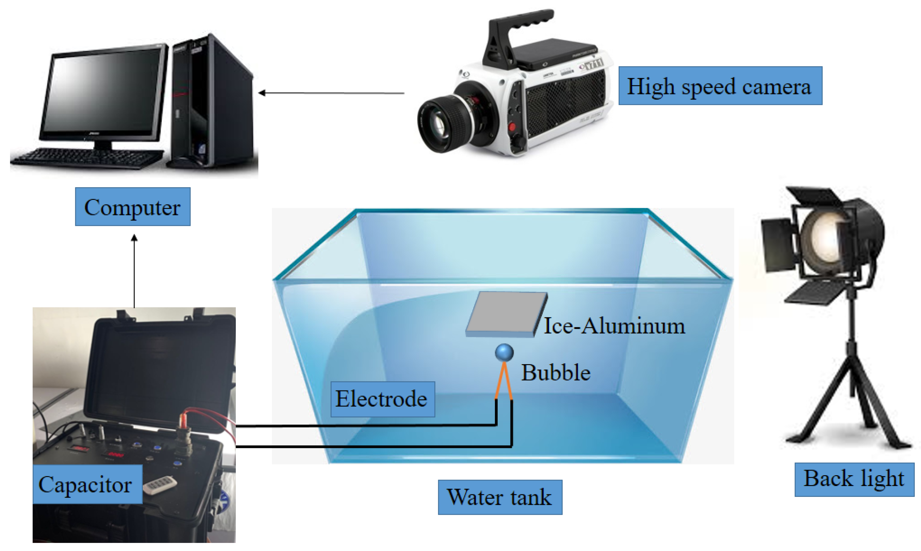
2.1. Electric Spark Bubble Experiment Device

The objective of this research was to utilize the energy generated by bubbles for the purpose of ice removal from a frozen structure. The bubble generator system employed in this study is based on an enhanced electric spark experiment conducted by Khoo. The power supply for discharge consisted of a 400 μF capacitor with a voltage rating of 600 V. Copper wires, each with a diameter of 0.2 mm, were used as the positive and negative electrodes, intersecting one another. Figure 1 illustrates the internal circuit diagram of the bubble generator. A transformer was utilized to convert a 220 V alternating current (AC) into a direct current (DC) power supply rated at 2000 V. This DC power supply charged the capacitor bank with a capacity of 400 μF to store and provide energy for bubble generation purposes. The spark discharge process could yield approximately 800 J available energy, which was estimated as follows:
E c = C U 2 / 2
The charging voltage, denoted as U, and the capacitance of the capacitor, denoted as C, are involved in this process. During the discharge of the capacitor bank, an ionized plasma zone is formed around the electrode. This leads to a high-temperature and high-pressure discharge, causing acceleration of the surrounding liquid. By applying voltage discharge between two electrodes, pulsating bubbles with high temperature and pressure are generated through their gap. These bubbles undergo expansion, followed by contraction and eventual collapse into jets that effectively break down ice layers on aluminum plates. This phenomenon has been experimentally verified by Cui et al. [40]. The proposed solution in this paper harnesses the energy from bubble pulsation to remove the ice layers adhered to aluminum plates.

2.2. EDM Bubble Scale Law

Through the aforementioned electric spark bubble generating device, the generated bubbles exhibited excellent repeatability. Specifically, when maintaining a constant voltage and utilizing the same overlapping method for the copper wire electrode, the size of the bubbles in the free field remained consistent. The intensity of the initial discharge energy was determined by the capacitance of the adjustable voltage transformer. Moreover, with a constant discharge voltage, there was a tendency toward a stable initial internal pressure within the bubble and determination of the maximum radius achieved through pulsation energy. After conducting numerous bubble experiments in free field using this experimental device, it was observed that different discharge voltages resulted in varying maximum bubble radii. However, when maintaining a certain level of discharge voltage, the maximum radius of the initial bubbles in the free field remained relatively uniform. Multiple sets of free-field bubble pulsation tests were conducted under different voltage conditions to group experimental measurement data and obtain average values for both maximum bubble radius and period. The relationship between the energy of the pulsation bubble and the maximum radius of the bubble can be estimated using the equation provided in [29].
E n = P · ( 4 π R max 3 / 3 )
where E n is the bubble energy, P is the ambient pressure, and R max denotes the maximum radius of the bubble.

3. Aluminum Plate Icing Technology

The plate used in this application was made of 5052 aluminum alloy, which had a tensile strength of approximately 175 MPa. It had a density of 2.72 g/cm3 and an elastic modulus of 70 GPa. Aluminum exhibits excellent low-temperature resistance, with its strength increasing as the temperature decreases. Additionally, it possesses superior ductility and is not prone to brittleness. These properties make it an ideal material for low-temperature equipment and have contributed to its widespread use in industries such as shipbuilding, aerospace, and machining. In this experiment, laser cutting technology was employed to precisely cut the aluminum plates into square shapes measuring 100 mm × 100 mm, with thicknesses ranging from 0.5 to 3 mm.
During the experiment, the freezing technique depicted in Figure 2 was employed, wherein two distinct freezing techniques (Figure 2a,b) were utilized to acquire two ice samples. The first sample constituted frost ice (Figure 2c), while the second type comprised block ice (Figure 2d). The frost ice sample was generated by simulating the icing process of an aluminum plate under air atomization conditions using an atomization and icing procedure (Figure 2a) [41]. Boiling hot water was introduced into a freezer, causing vapor to evaporate and come into contact with an aluminum plate, thereby leading to droplet formation through atomization. As a result of temperature fluctuations and energy conversion, an icy layer gradually formed on the aluminum plate over approximately 36 h until it reached the desired thickness of 5~30 mm, resulting in the attainment of a frosty ice sample, as illustrated in Figure 2c.
The block ice sample was obtained using specialized directional freezing technology to simulate the icing process (Figure 2b). A square container made of thermal insulation material, without a top cover, was utilized. An aluminum plate was horizontally fixed on the top of the container, and boiling hot water was injected from the bottom. Due to the insulation on the bottom and sides of the container, water freezing occurred gradually. The surface of the aluminum plate in contact with water and air reached its freezing point first, initiating a top-down freezing process. The temperature inside the container remained constant throughout, and, after 48 h, a frozen ice sample was obtained from the aluminum (Figure 2d). The ice sample was then removed from the top and cut into various thicknesses for use in subsequent experiments ranging from 5 to 30 mm. The Young’s modulus of this obtained ice measured at 9.31 GPa, with a Poisson’s ratio of 0.33.

4. Bubble Deicing System Set-Up

A schematic diagram of the bubble deicing system utilized in this study is presented in Figure 3. The system consisted of several components, including a spark bubble generator, a transparent experimental water tank (500 mm × 500 mm × 500 mm), LED lights (GS Vitec Multi LED LT-V8-11 with 7700 lumens) to avoid light-source interference and ensure effective image capture, a high-speed camera (Vision Research Phantom V711) capable of capturing up to 24,000–58,000 frames per second with an exposure time of 10~20 ms, a Nikkor lens (50 mm F2.8), and a computer. The working process of the bubble deicing device is illustrated in Figure 3.
The operational procedure of the bubble deicing device is as follows:
(1) Deionized water was added to a plexiglass water tank (500 mm × 500 mm × 500 mm) up to a height of 30 cm, while ensuring the water in the tank remained degassed. In order to maintain consistent deicing effects, it was necessary to control the temperature of the water before placing the prepared aluminum–ice board into the tank. This was achieved by regulating the water tank temperature through the addition of ice cubes, resulting in a controlled temperature of 5 °C.
(2) The LED light was positioned on the right side of the water tank, while the high-speed camera was placed in front of it. The camera’s shooting angle was adjusted to ensure optimal capture of the fractured area on the ice sheet.
(3) The clutch was securely mounted on the wall of the water tank to firmly secure the ice-covered aluminum plate, while the bubble-generating device was positioned at the lower section of the tank. Two copper pillar electrodes were installed beneath the water tank’s free surface to ensure that the ice–aluminum plate structure remained fixed in a specific location on top of the liquid surface.
(4) The water was rapidly heated upon insertion of the positive and negative electrodes, resulting in the formation of expanding bubbles. As these bubbles reached their maximum size, they began to contract, leading to the generation of jets and shock waves. The energy released during this process effectively removed the ice layer adhered to the aluminum plate.

5. Experimental Study of Efficiency of Bubble Deicing

The bubble deicing process involved the utilization of different bubble distance parameters, namely, long, medium, and short distances. Additionally, various ice plates with varying thicknesses were employed, including thick ice plates, medium thick ice plates, and thin ice plates. To accurately capture the dynamics of the deicing process and the subsequent separation of the ice plate from the aluminum plate at high speed, multiple camera angles were utilized: front view, oblique view, and bottom view. These angles facilitated recording the shapes of both the bubbles during deicing and the cracks formed during separation. Moreover, a comprehensive analysis was conducted to establish a correlation between bubble deicing efficiency and specific nondimensional parameters presented below.

5.1. Dimensionless Parameters

To standardize the experimental results, the maximum bubble radius R max is commonly employed as the characteristic length for dimensionless parameterization. It is determined by averaging measurements from over 100 experiments conducted under identical discharge voltage conditions. For instance, at a discharge voltage of 600 V, the maximum bubble radius was approximately 18.0 mm with a standard deviation of 0.54 mm. In this experiment, the dimensionless distance parameter was defined as d, representing the distance from the center of the initial bubble to the lower surface of an ice–aluminum plate, while considering the thickness of ice ( t ice ):
γ = d R max
T ice = t ice R max
In order to estimate the efficiency of the bubble deicing system approximately, the deicing rate was defined as follows:
d = A r A 0
in which d denotes the deicing rate, A r is the removal ice area, and A 0 is the total icing area.

5.2. Bubble Distance and Deicing Efficiency

The bubble distance is a crucial parameter that significantly impacts the ice-breaking capability. This section examines the influence of selecting different bubble distances on the effectiveness of removing the ice layer adhered to the aluminum plate structure.

5.2.1. Large-Distance Deicing

The dynamics of a single air bubble initially placed at a significant distance ( γ = 1.78 ) from the aluminum plate, in the presence of thin ice ( T i c e = 0.39 ), are depicted in Figure 4. It can be observed that the application of sparks from the positive and negative electrodes led to continuous expansion of the bubble (frames 1 and 2). Under internal high pressure, the bubble reached its maximum size (frame 3). Subsequently, it started to shrink (frames 47), with the top being attracted toward the ice while the bottom formed a jet-like shape. As soon as the bubble shrank to its minimum size, a jet was directed toward the ice (frame 8). This jet induced cracking on the ice plate without any contact between the bubbles/jet and ice–aluminum plate prior to fracture occurrence. This phenomenon aligns with Zhang’s research conclusion [40], where an initial shock wave is released upon impact between jet and upper boundary of bubble ring formed after penetration. The resulting secondary reflected waves (compression waves and expansion waves) caused cracks on the ice plate, leading to separation between the ice and aluminum plate. In frames 9 and 10, bubbles expanded again, followed by collapse (frames 11 and 12). Considering the material characteristics of ice, circumferential stress first exceeds the allowable stress for ice; hence, circumferential cracks appear in this scenario. Due to substantial distance between bubbles and ice plate, initial shock wave rapidly attenuates resulting in small crack area with crushing range approximately around 10 % .

5.2.2. Middle-Distance Deicing

The dimensionless ice thickness parameter, the deformation of deicing at an intermediate distance, and its impact on the aluminum plate coated with ice can be observed in Figure 5. When the distance between the bubble and the ice was at an intermediate value, a jet formed during bubble bursting and impacted the ice-coated aluminum plate before reaching its minimum volume. Prior to jet formation, there was only a small amount of air present in a narrow gap. The jet penetrated this gap and struck the ice surface, resulting in cracks appearing on the ice plate (frame 9), while simultaneously causing the expansion, contraction, and eventual collapse of bubbles. At this stage, approximately 80% of the total area experienced deicing.

5.2.3. Near-Distance Eeicing

The bubble deicing effect of the ice plate at a temperature of T ice = 0.83 and at close range γ = 0.44 is illustrated in Figure 6. The bubble made contact with the ice-coated aluminum plate before collapsing. During the expansion phase, the bubble adhered to the surface of the ice plate, resulting in a hemispherical shape (frame 4). The upper half formed a suction cup due to the interaction between the ice and aluminum, while the lower end continued shrinking until it formed a sharp corner (frame 8), with its center pointing upward toward the frozen structure to create a jet (frame 10). This jet rapidly moved at a certain speed and formed a ring at its base, giving rise to circular bubbles (frame 15). Throughout this process, no cracking or detachment was observed in the ice–aluminum structure. In frame 16, these “bubble rings” caused the initial breakage of the ice layer starting from its interface with the aluminum and expanding further. Ultimately, an approximate deicing efficiency of about 90% was achieved.

5.3. Influence of Ice Type on Deicing Efficiency

Due to the intricate mechanical properties of ice, the interactions between ice and bubbles were stochastic, resulting in varying sizes, quantities, and configurations of ice cracks, leading to distinct crack patterns and failure modes. We employed ice–aluminum structures with different thicknesses to investigate the deicing efficacy of the bubbles.

5.3.1. Thick, Lumpy Ice

A block ice–aluminum plate sample was selected, with an ice plate thickness ranging from 25 to 30 mm and a temperature range of T i c e = 1.39~1.67. Considering the influence of the ice cutting process, as well as room and water temperatures, there was an approximate error of 1 mm in the measured ice plate thickness. Figure 7 illustrates the deicing process and range for a typical thick ice plate under the effect of bubbles. The cracks observed in the thick ice plate were predominantly radial.
After the expansion and contraction of bubbles to their minimum volume, a jet was formed (frame 4). This jet initiated the initial crack in the ice plate (frame 5), which subsequently began to propagate and expand (frames 5 and 6). The bubble underwent a second expansion and contraction, leading to a secondary impact in frame 11, resulting in further crack propagation. Frame 12 depicts the final formation of a crack that covered approximately 40% of the ice-coated aluminum plate’s surface area.

5.3.2. Medium, Lumpy Ice

The selected sample consisted of an aluminum plate with block ice, and the ice thickness ranged from 15 to 20 mm, T i c e = 0.83~1.11.
The front view revealed the presence of bubbles and the fracture of ice in the vertical thickness direction. As depicted in Figure 8, even without direct contact with the ice–aluminum plate structure, the ejection of bubbles resulted in the surface breakage of the ice. The initial rupture occurred at the interface between the ice and aluminum plate due to the reflection of the pressure waves generated by impact. This reflection caused an expansion wave at the ice–aluminum plate interface, inducing tension that led to the detachment of the ice from the aluminum plate.
The initiation, bifurcation, and expansion of ice cracks under the influence of the shock waves generated by the bubbles was observed from a bottom view. As depicted in Figure 9, during the initial expansion stage of the bubble (frame 2), small cracks appeared on the ice surface in the case of short-distance γ = 0.28 bubble deicing. Due to the proximity, the energy transmitted to the ice surface during bubble expansion led to further crack propagation. Subsequently, with bubble contraction and jet formation, the impact on the ice resulted in secondary crack propagation. In scenarios involving a medium ice thickness, irregular “square”-shaped cracks were observed instead of the radial cracks seen in the thicker cases. A third crack tear occurred when the bubble shrank again to its limit. The bursting of bubbles released a series of shock waves, which caused cracking in the ice due to their rebound effect, consequently converting shockwave energy into the fracture energy responsible for crack splitting. The deicing time under these conditions was 0.96 ms.

5.3.3. Thin, Lumpy Ice

For ice thicknesses ranging from 5 to 10 mm, the value of T i c e varied between 0.28 and 0.56, with different conditions for ice removal compared to the typical example shown in Figure 10. The initiation of a crack led to bubble expansion (frame 2). This initial crack was radial in nature, and the contraction of the bubble resulted in a secondary split (frame 11). The last crack bifurcation occurred at frame 18. The thinner ice attached to the aluminum plate experienced a bending moment due to the expansion of bubbles, resulting in a relatively short propagation distance from top to bottom. As a result, early reflection vibrations occurred, leading to fragmentation. The entire deicing process lasted 1.45 ms.

5.3.4. Frost Ice

The process of bubble removal from “frost” ice is illustrated in Figure 11. It can be observed that the bubble was absorbed by the “frost” ice, resulting in the formation of sharp corners during the initial expansion stage, which continued to elongate. Subsequently, the bubbles started to shrink and took on a shape resembling an “egg” in the fifth frame. An intriguing phenomenon was that even during the contraction stage, the bubbles were still attracted by the frost ice. The contraction did not occur uniformly but rather exhibited a “necking” effect at its midpoint (frame 7). The upper part of the bubble experienced tension and was attracted toward it, while contracting at a slower rate compared to the rapid shrinking of its lower part, forming an umbrella-like structure, as shown in frame 9. Eventually, the bubble reached its limit state through further shrinkage (frame 10). Unlike lumpy ice, where jets emerged from below upon contraction, with frosty ice, they were emitted from above instead. The top and bottom sections of these bubbles were separated by a narrow ring around their middle portion, referred to as “necked”. Once jetting occurred, there was subsequent expansion at their bottom section and collapse at their top section. Frosty ice proved to be easier to remove due to its ability to be completely deiced even with lower energy input.

5.3.5. Deicing Mode

The relationship between the efficiency of bubble deicing, denoted as T i c e , and γ is illustrated in Figure 12. Based on repeated experimental results, the factors influencing the deicing efficiency T i c e are the dimensionless ice thickness and the dimensionless distance γ . From Figure 12, it can be observed that the highest deicing rate occurred within a range of dimensionless bubble distances from 0.44 to 1.78 and dimensionless ice thicknesses from 0.28 to 1.39. When the ice thickness exceeded 1.6, it became challenging to completely remove ice from the aluminum plate in a single attempt. For ice plates with a thickness below 1.6, selecting a bubble distance less than 1.0 yielded deicing rates ranging from 50% to 80%. In cases of thicker ice, bubbles could not be removed from the aluminum plate after one trial; multiple deicing processes were required instead. Conversely, thin ice could be removed in one trial by maintaining a certain bubble distance.

6. Conclusions

In this study, a novel bubble deicing system was developed, and its potential for removing ice from frozen structures using bubble pulsation energy was investigated. The mechanism and mode of the deicing process were examined, including variations in bubble size and thickness of the ice coating on an aluminum plate. A comprehensive understanding of the bubble deicing process and its underlying mechanisms was obtained. The main conclusions drawn from this research are as follows:
(1) The energy released by bubbles can effectively remove an ice layer adhered to an aluminum plate structure. The pulsating pressure exerted by the bubbles serves as the primary load source for deicing purposes. The forceful jet of bubbles plays a crucial role in facilitating deicing, and, even without direct contact with the ice-aluminum structure, the energetic impact of the bubbles alone is sufficient to fracture the ice surface.
(2) The efficiency of deicing is dependent on the distance between bubbles and the ice surface. Bubbles exhibit three distinct behaviors when interacting with an aluminum structure covered in ice. During short-distance deicing ( γ = 0.44 ), the bubble behavior primarily involves a directed jet toward the ice followed by annular bubble formation. In long-distance deicing ( γ = 1.78 ), the bubbles collapse at a distant location after jetting. When dealing with “frosty” ice, bubbles form at both the upper and lower ends, resulting in the phenomena of “necking” and “separation”.
(3) The formation pattern of cracks in the ice is correlated with the thickness of the ice. Radial cracks predominantly occur in thicker transparent block ice, ranging from 25 mm to 30 mm, while circumferential cracks are more likely to appear in thinner ice, ranging from 5 mm to 10 mm. The movement of bubbles follows a regular pattern, whereas the fragmentation of the ice exhibits high randomness, which can be attributed to the intricate physical properties of ice.
(4) The deicing efficiency is influenced by the nondimensional ice thickness T i c e and the nondimensional distance γ . The deicing ratio varies under different parameter conditions. Multiple deicing processes are required for thicker transparent block ice, while “frosty” ice is easier to remove due to sufficient bubble energy, resulting in a 100% deicing efficiency achieved at once. The established deicing system in this study serves as a reference for utilizing new energy sources to address engineering deicing issues. Bubble deicing technology, as an innovative method, exhibits promising prospects in renewable energy utilization. Bubbles are easily obtainable with low energy costs and are environmentally friendly, thereby providing high deicing efficiency. Consequently, bubble energy is anticipated to be extensively employed in resolving various engineering problems, particularly those related to deicing.

Author Contributions

Y.S.: Methodology, data curation, visualization, and writing. S.Z.: Investigation and review editing. S.W.: Validation, funding acquisition, and review editing. Z.K.: Supervision, resources, and review editing. All authors have read and agreed to the published version of this manuscript.

Funding

This work was supported by the National Natural Science Foundation of China (grant No. 51979049, grant No. 51909041).

Institutional Review Board Statement

Not applicable.

Informed Consent Statement

Not applicable.

Data Availability Statement

The original contributions presented in the study are included in the article, further inquiries can be directed to the corresponding author.

Conflicts of Interest

The authors declare that they have no known competing financial interests or personal relationships that could have appeared to influence the work reported in this paper.

References

  1. Wang, Y.; Xu, Y.; Huang, Q. Progress on ultrasonic guided waves deicing techniques in improving aviation energy efficiency. Renew. Sustain. Energy Rev. 2017, 79, 638–645. [Google Scholar] [CrossRef]
  2. Wang, S.; Liu, L.; Xu, Q.; Liang, D.; Ji, S. A unified Minkowski sum model for largely deformed granular materials with arbitrary morphologies. Comput. Methods Appl. Mech. Eng. 2024, 432, 117427. [Google Scholar] [CrossRef]
  3. Wang, Q.; Yi, X.; Liu, Y.; Ren, J.; Li, W.; Wang, Q.; Lai, Q. Simulation and analysis of wind turbine ice accretion under yaw condition via an improved multi-shot icing computational model. Renew. Energy 2020, 162, 1854–1873. [Google Scholar] [CrossRef]
  4. Zhang, A.M.; Li, S.-M.; Xu, R.-Z.; Pei, S.-C.; Li, S.; Liu, Y.-L. A theoretical model for compressible bubble dynamics considering phase transition and migration. J. Fluid Mech. 2024, A58, 999. [Google Scholar] [CrossRef]
  5. Ding, L.; Chang, S.; Yi, X.; Song, M. Coupled thermo-mechanical analysis of stresses generated in impact ice during in-flight deicing. Appl. Therm. Eng. 2020, 181, 115681. [Google Scholar] [CrossRef]
  6. Zhou, L.; Riska, K.; und Polach, R.; Moan, T.; Su, B. Experiments on level ice loading on an icebreaking tanker with different ice drift angles. Cold Regions Sci. Technol. 2013, 85, 79–93. [Google Scholar] [CrossRef]
  7. Ma, L.; Zhang, Z.; Gao, L.; Liu, Y.; Hu, H. An exploratory study on using slippery-liquid-infused-porous-surface (slips) for wind turbine icing mitigation. Renew. Energy 2020, 162, 2344–2360. [Google Scholar] [CrossRef]
  8. Sun, J.; Huang, Y. Investigations on the ship-ice impact: Part 1. Experimental methodologies. Mar. Struct. 2020, 72, 102772. [Google Scholar] [CrossRef]
  9. Wang, Y.; Xu, Y.; Su, F. Damage accumulation model of ice detach behavior in ultrasonic deicing technology. Renew. Energy 2020, 153, 1396–1405. [Google Scholar] [CrossRef]
  10. Zhang, A.; Chuang, Z.; Liu, S.; Zhou, L.; Qu, Y.; Lu, Y. Dynamic performance optimization of an arctic semi-submersible production system. Ocean Eng. 2022, 244, 110353. [Google Scholar] [CrossRef]
  11. Habibi, H.; Cheng, L.; Zheng, H.; Kappatos, V.; Selcuk, C.; Gan, T.H. A dual deicing system for wind turbine blades combining high-power ultrasonic guided waves and low-frequency forced vibrations. Renew. Energy 2015, 83, 859–870. [Google Scholar] [CrossRef]
  12. Chai, W.; Leira, B.J.; Naess, A. Probabilistic methods for estimation of the extreme value statistics of ship ice loads. Cold Reg. Sci. Technol. 2018, 146, 87–97. [Google Scholar] [CrossRef]
  13. Wang, Y.; Xu, Y.; Lei, Y. An effect assessment and prediction method of ultrasonic deicing for composite wind turbine blades. Renew. Energy 2018, 118, 1015–1023. [Google Scholar] [CrossRef]
  14. Zhang, J.; Gaidai, O.; Wang, K.; Xu, J.; Ye, R.; Xu, X. A stochastic method for the prediction of icebreaker bow extreme stresses. Appl. Ocean Res. 2019, 87, 95–101. [Google Scholar] [CrossRef]
  15. Gao, L.; Liu, Y.; Zhou, W.; Hu, H. An experimental study on the aerodynamic performance degradation of a wind turbine blade model induced by ice accretion process. Renew. Energy 2019, 133, 663–675. [Google Scholar] [CrossRef]
  16. Sun, S.; Shen, H.H. Simulation of pancake ice load on a circular cylinder in a wave and current field. Cold Reg. Sci. Technol. 2012, 78, 31–39. [Google Scholar] [CrossRef]
  17. Rashid, T.; Khawaja, H.A.; Edvardsen, K. Review of marine icing and anti-/deicing systems. J. Mar. Eng. Technol. 2016, 15, 79–87. [Google Scholar] [CrossRef]
  18. Zhang, D.; Wang, G.; Yue, Q. Evaluation of ice-induced fatigue life for a vertical offshore structure in the Bohai Sea. Cold Reg. Sci. Technol. 2018, 154, 103–110. [Google Scholar] [CrossRef]
  19. Huttunen-Saarivirta, E.; Kuokkala, V.T.; Kokkonen, J.; Paajanen, H. Corrosion behaviour of aircraft coating systems in acetate-and formate-based deicing chemicals. Mater. Corros. 2009, 60, 173–191. [Google Scholar] [CrossRef]
  20. Nguyen, T.B.; Park, S.; Lim, H. Effects of morphology parameters on anti-icing performance in superhydrophobic surfaces. Appl. Surf. Sci. 2018, 435, 585–591. [Google Scholar] [CrossRef]
  21. Shen, Y.; Wang, G.; Tao, J.; Zhu, C.; Liu, S.; Jin, M.; Xie, Y.; Chen, Z. Anti-icing performance of superhydrophobic texture surfaces depending on reference environments. Adv. Mater. Interfaces 2017, 4, 1700836. [Google Scholar] [CrossRef]
  22. Thomas, S.K.; Cassoni, R.P.; MacArthur, C.D. Aircraft anti-icing and deicing techniques and modeling. J. Aircr. 1996, 33, 841–854. [Google Scholar] [CrossRef]
  23. Mohammed, A.G.; Ozgur, G.; Sevkat, E. Electrical resistance heating for deicing and snow melting applications: Experimental study. Cold Reg. Sci. Technol. 2019, 160, 128–138. [Google Scholar] [CrossRef]
  24. Zhao, Z.; Chen, H.; Liu, X.; Liu, H.; Zhang, D. Development of high-efficient synthetic electric heating coating for anti-icing/deicing. Surf. Coatings Technol. 2018, 349, 340–346. [Google Scholar] [CrossRef]
  25. Li, B.; He, L.; Liu, Y.; Luo, J.; Zhang, G. Influences of key factors in hot-air deicing for live substation equipment. Cold Reg. Sci. Technol. 2019, 160, 89–96. [Google Scholar] [CrossRef]
  26. Wang, Y.; Yue, Q.; Guo, F.; Bi, X.; Shi, Z.; Qu, Y. Performance evaluation of a new ice-resistant jacket platform based on field monitoring. Cold Reg. Sci. Technol. 2012, 71, 44–53. [Google Scholar] [CrossRef]
  27. Shu, L.; Qiu, G.; Hu, Q.; Jiang, X.; McClure, G.; Liu, Y. Numerical and experimental investigation of threshold deicing heat flux of wind turbine. J. Wind. Eng. Ind. Aerodyn. 2018, 174, 296–302. [Google Scholar] [CrossRef]
  28. Yue, Q.; Guo, F.; Kärnä, T. Dynamic ice forces of slender vertical structures due to ice crushing. Cold Reg. Sci. Technol. 2009, 56, 77–83. [Google Scholar] [CrossRef]
  29. Liu, Y.; Kolbakir, C.; Hu, H.; Hu, H. A comparison study on the thermal effects in dbd plasma actuation and electrical heating for aircraft icing mitigation. Int. J. Heat Mass Transf. 2018, 124, 319–330. [Google Scholar] [CrossRef]
  30. Ding, L.; Wang, X.; Cui, X.; Zhang, M.; Chen, B. Development and performance research of new sensitive materials for microwave deicing pavement at different frequencies. Cold Reg. Sci. Technol. 2021, 181, 103176. [Google Scholar] [CrossRef]
  31. Liu, X.; Chen, H.; Zhao, Z.; Yan, Y.; Zhang, D. Slippery liquid-infused porous electric heating coating for anti-icing and deicing applications. Surf. Coatings Technol. 2019, 374, 889–896. [Google Scholar] [CrossRef]
  32. Hao, L.; Li, Q.; Pan, W.; Li, B. Icing detection and evaluation of the electro-impulse deicing system based on infrared images processing. Infrared Phys. Technol. 2020, 109, 103424. [Google Scholar] [CrossRef]
  33. Koenig, G.G.; Ryerson, C.C. An investigation of infrared deicing through experimentation. Cold Reg. Sci. Technol. 2011, 65, 79–87. [Google Scholar] [CrossRef]
  34. Zeng, J.; Song, B. Research on experiment and numerical simulation of ultrasonic deicing for wind turbine blades. Renew. Energy 2017, 113, 706–712. [Google Scholar] [CrossRef]
  35. Daniliuk, V.; Xu, Y.; Liu, R.; He, T.; Wang, X. Ultrasonic deicing of wind turbine blades: Performance comparison of perspective transducers. Renew. Energy 2020, 145, 2005–2018. [Google Scholar] [CrossRef]
  36. Zilioniene, D.; Laurinavicius, A. deicing experience in lithuania. Balt. J. Road Bridge Eng. 2007, 2, 73–79. [Google Scholar]
  37. Deng, Y.; Li, Z.; Li, Z.; Wang, J. The experiment of fracture mechanics characteristics of Yellow River Ice. Cold Reg. Sci. Technol. 2019, 168, 102896. [Google Scholar] [CrossRef]
  38. Zhang, A.; Liu, Y. Improved three-dimensional bubble dynamics model based on boundary element method. J. Comput. Phys. 2015, 294, 208–223. [Google Scholar] [CrossRef]
  39. Zhang, A.; Yang, W.S.; Huang, C.; Ming, F. Numerical simulation of column charge underwater explosion based on sph and bem combination. Comput. Fluids 2013, 71, 169–178. [Google Scholar] [CrossRef]
  40. Cui, P.; Zhang, A.M.; Wang, S.; Khoo, B.C. Ice breaking by a collapsing bubble. J. Fluid Mech. 2018, 841, 287. [Google Scholar] [CrossRef]
  41. Cui, P.; Zhang, A.M.; Wang, S.P.; Liu, Y.L. Experimental study on interaction, shock wave emission and ice breaking of two collapsing bubbles. J. Fluid Mech. 2020, 897, A25. [Google Scholar] [CrossRef]
  42. Zhang, A.M.; Li, S.-M.; Cui, P.; Li, S.; Liu, Y.-L. A unified theory for bubble dynamics. Phys. Fluids 2023, 35, 3. [Google Scholar] [CrossRef]
  43. Kan, X.Y.; Zhang, A.M.; Yan, J.L.; Wu, W.B.; Liu, Y.L. Numerical investigation of ice breaking by a high-pressure bubble based on a coupled bem-pd model. J. Fluids Struct. 2020, 96, 103016. [Google Scholar] [CrossRef]
  44. Yuan, G.Y.; Ni, B.Y.; Wu, Q.G.; Xue, Y.Z.; Zhang, A.M. An experimental study on the dynamics and damage capabilities of a bubble collapsing in the neighborhood of a floating ice cake. J. Fluids Struct. 2020, 92, 102833. [Google Scholar] [CrossRef]
  45. Buogo, S.; Plocek, J.; Vokurka, K. Efficiency of energy conversion in underwater spark discharges and associated bubble oscillations: Experimental results. Acta Acust. United Acust. 2009, 95, 46–59. [Google Scholar] [CrossRef]
  46. Lu, P.; Leppäranta, M.; Cheng, B.; Li, Z. Influence of melt-pond depth and ice thickness on Arctic sea-ice albedo and light transmittance. Cold Reg. Sci. Technol. 2016, 124, 1–10. [Google Scholar] [CrossRef]
  47. Zhang, A.; Ni, B. Influences of different forces on the bubble entrainment into a stationary gaussian vortex. Sci. China Physics Mech. Astron. 2013, 56, 2162–2169. [Google Scholar] [CrossRef]
  48. Sun, Y.; Timoshkin, I.V.; Given, M.J.; Wilson, M.P.; Wang, T.; MacGregor, S.J.; Bonifaci, N. Acoustic impulses generated by air-bubble stimulated underwater spark discharges. IEEE Trans. Dielectr. Electr. Insul. 2018, 25, 1915–1923. [Google Scholar] [CrossRef]
  49. Gong, S.; Goh, B.; Ohl, S.W.; Khoo, B.C. Interaction of a spark-generated bubble with a rubber beam: Numerical and experimental study. Phys. Rev. E 2012, 86, 026307. [Google Scholar] [CrossRef]
  50. Wang, Q.; Li, Z.; Lei, R.; Lu, P.; Han, H. Estimation of the uniaxial compressive strength of Arctic Sea ice during melt season. Cold Reg. Sci. Technol. 2018, 151, 9–18. [Google Scholar] [CrossRef]
  51. Aleshkin, M. A technique for suppressing bubble oscillations from an air gun during shallow-water marine seismic surveying. Mosc. Univ. Geol. Bull. 2020, 75, 305–308. [Google Scholar] [CrossRef]
  52. Zhang, A.; Li, S.; Cui, J. Study on splitting of a toroidal bubble near a rigid boundary. Phys. Fluids 2015, 27, 062102. [Google Scholar] [CrossRef]
  53. Li, S.; Zhang, A.M.; Han, R.; Ma, Q. 3D full coupling model for strong interaction between a pulsating bubble and a movable sphere. J. Comput. Phys. 2019, 392, 713–731. [Google Scholar] [CrossRef]
  54. Zhang, A.; Wu, W.; Liu, Y.; Wang, Q. Nonlinear interaction between underwater explosion bubble and structure based on fully coupled model. Phys. Fluids 2017, 29, 082111. [Google Scholar] [CrossRef]
  55. Liu, Y.L.; Zhang, A.M.; Tian, Z.L.; Wang, S.P. Dynamical behavior of an oscillating bubble initially between two liquids. Phys. Fluids 2019, 31, 092111. [Google Scholar]
  56. Li, S.; Zhang, A.M.; Han, R.; Cui, P. Experimental and numerical study of two underwater explosion bubbles: Coalescence, fragmentation and shock wave emission. Ocean. Eng. 2019, 190, 106414. [Google Scholar] [CrossRef]
  57. Han, R.; Li, S.; Zhang, A.; Wang, Q. Modelling for three dimensional coalescence of two bubbles. Phys. Fluids 2016, 28, 062104. [Google Scholar] [CrossRef]
  58. Zhang, A.; Cui, P.; Cui, J.; Wang, Q. Experimental study on bubble dynamics subject to buoyancy. J. Fluid Mech. 2015, 776, 15. [Google Scholar] [CrossRef]
Figure 1. Schematic diagram of bubble deicing components. (a) Circuit inside. (b) Deicing bubble generator plate.
Jmse 12 02211 g001
Figure 2. Schematic of freezing techniques and obtained ice. (a) Freezing technology for frost ice. (b) Directional freezing technology. (c) Frost ice sample. (d) Block ice sample.
Jmse 12 02211 g002
Figure 3. Schematic of the bubble deicing system.
Jmse 12 02211 g003
Figure 4. Time series of bubble dynamics showing the bubble jet impact on the ice–aluminum plate. Bubble and jet not in contact with the ice; shock wave removed ice from the aluminum plate.
Jmse 12 02211 g004
Figure 5. Medium- distance bubble deicing (jet formed from the bottom, turned into ring, and impacted the ice).
Jmse 12 02211 g005
Figure 6. Near-distance deicing (jet formed from the bottom of the bubble; ice breaking initialized from the interface of the ice and aluminum).
Jmse 12 02211 g006
Figure 7. Thick ice crack patterns produced by bubble impact.
Jmse 12 02211 g007
Figure 8. Removal process of medium thickness ice.
Jmse 12 02211 g008aJmse 12 02211 g008b
Figure 9. Medium-thickness ice crack pattern produced by bubble impact.
Jmse 12 02211 g009aJmse 12 02211 g009b
Figure 10. Medium- thickness ice crack pattern produced by bubble impact.
Jmse 12 02211 g010aJmse 12 02211 g010b
Figure 11. Near-distance deicing (Frost ice).
Jmse 12 02211 g011aJmse 12 02211 g011b
Figure 12. Relationship between deicing possibility with ice thickness T i c e and distance γ .
Jmse 12 02211 g012
Disclaimer/Publisher’s Note: The statements, opinions and data contained in all publications are solely those of the individual author(s) and contributor(s) and not of MDPI and/or the editor(s). MDPI and/or the editor(s) disclaim responsibility for any injury to people or property resulting from any ideas, methods, instructions or products referred to in the content.

