Article

Study of the Combustion Characteristics of a Compression Ignition Engine Fueled with a Biogas–Hydrogen Mixture and Biodiesel

by
Alfredas Rimkus
1 and
Justas Žaglinskis
2,*
1
Department of Automobile Engineering, Faculty of Transport Engineering, Vilnius Gediminas Technical University, Plytines Str. 25, 10105 Vilnius, Lithuania
2
Lithuanian Maritime Academy, Vilnius Gediminas Technical University, I. Kanto 7, 92123 Klaipeda, Lithuania
*
Author to whom correspondence should be addressed.
J. Mar. Sci. Eng. 2024, 12(12), 2192; https://doi.org/10.3390/jmse12122192
Submission received: 4 November 2024 / Revised: 27 November 2024 / Accepted: 28 November 2024 / Published: 30 November 2024

Abstract

:
Increasing the use of renewable energy sources is essential to reduce the use of fossil fuels in internal combustion engines and to reduce greenhouse gas emissions. An experimental and numerical simulation study of the combustion process of a compression ignition engine was carried out by replacing fossil diesel with a dual fuel produced from renewable energy sources. In conventional dual-fuel applications, fossil diesel is used to initiate the combustion of natural gas or petroleum gas. In the present study, fossil diesel was replaced with advanced biodiesel – hydrotreated vegetable oil, and natural gas was replaced with biogas. In the experimental study, a gas mixture of 60% natural gas (by volume) and 40% carbon dioxide (by volume) was used to replicate the biogas while maintaining a 40%, 60%, and 80% gas energy share in the fuel. It was observed that using fossil diesel and biogas in the dual-fuel engine significantly slowed down the combustion process, which normally resulted in poorer energy performance. One way to compensate for the lack of energy (due to the presence of carbon dioxide) in the cylinder is to use a gas such as hydrogen, which has a high energy content. To analyze the effect of hydrogen on the dual-fuel combustion process, hydrogen gas was added to the replicated biogas at 10%, 20%, and 30% of the natural gas volume, maintaining the biogas at a (natural gas + hydrogen)-to-carbon dioxide volume ratio of 60%/40% and the expected gas energy share. The combustion process analysis, which was conducted using the AVL BOOST software (Austria), determined the heat release rate, temperature, and cylinder pressure rise in the dual-fuel operation with different renewable fuels and compared the results with those of fossil diesel. It was found that when the engine was operated at medium load and with the flammability of the biogas approaching the limit, the addition of hydrogen significantly improved the combustion characteristics of the dual-fuel engine.

1. Introduction

According to Article 194(1) of the Treaty on the Functioning of the European Union (TFEU), the promotion of the development of renewable energy sources is one of the main objectives of the energy policy of the EU [1]. Directive (EU) 2018/2001 of the European Parliament and of the Council aims to achieve this objective. The increased use of renewable energy is an essential tool to reduce greenhouse gas emissions and to meet the commitments of the EU under the 2015 Paris Agreement on climate change. It is also an important step towards implementing the EU’s 2030 Climate and Energy Strategy, which includes mandatory emission reductions of at least 40% by 2030 compared to 1990 levels. The use of renewable fuels was planned and described in the White Paper 2011 and the recent Directive (EU) 2018/2001 [1,2].
The use of advanced fuels and gases (including hydrogen) produced from renewable energy sources and the use of renewable electricity in the transport sector have the potential to reduce carbon emissions, thereby creating incentives to cost-effectively reduce the EU transport sector’s dependence on fossil fuels, thereby increasing the diversity of energy sources in the transport sector while stimulating innovation, growth, and jobs in the EU economy and reducing dependence on energy imports [1,2].
Biogas is a type of renewable fuel, with livestock farms, sewage treatment systems, and landfills being the main sources [3,4]. Biogas is based on methane (CH4), carbon dioxide (CO2), and other compounds, including highly harmful sulfur compounds [5,6]. Biogas is widely used in spark ignition (SI) engines, which are fed directly with biogas or filtered with filters designed to remove sulfur compounds [7,8]. Once sulfur compounds have been eliminated, the volume composition of biogas, according to various sources [9,10,11], is as follows: CH4 50–80%; CO2 20–50%; remaining compounds (O2, H2, N2, CO) 0 to 10%.
The use of biogas in the transport and energy sector is important from both an energy and environmental point of view, as it is not only a renewable feedstock for fuels, but it also reduces the uncontrolled release of anthropogenic CH4 from landfills, centralized wastewater treatment systems, and livestock farms. The latter factor is important, as uncontrolled CH4 released into the environment has a 27-30 times higher greenhouse effect (100-year GWP) compared to equivalent CO2 gases [12,13].
For maritime transport, fuels made from renewable energy sources (RESs) are as relevant as for land transport and the energy sector. The gradual substitution of petroleum distillates and residual fuels by natural gas (NG) aims to meet the increasing environmental requirements and diversify the fuel supply chain [14,15,16]. However, NG is not extracted from renewable sources in a way that is close to oil extraction. Methane, extracted from biogas purification, can be a substitute for NG. In this case, the realization of an RES in ship propulsion systems can be ensured and high environmental requirements can be met. It is known that the use of gas in marine propulsion requires a dual-fuel (D-F) cycle [17,18], in which methane combustion is initiated by liquid petroleum fuels, and therefore, its substitution by fuels derived from RESs remains an issue.
As mentioned, in compression ignition engines (CI-ICEs), widely used in the transport and energy sectors, the use of biogas is only possible in a D-F cycle, i.e., when using liquid and gaseous fuels [19,20]. The D-F cycle of NG with fossil diesel used to ignite it is commonly used in marine, heavy land transport, and power generation applications [17,18]. Both fossil diesel and NG are not classified as fuels produced from RESs. In order to increase energy efficiency and reduce emissions, a number of research studies have been carried out using various bio-based fuels instead of fossil diesel to initiate NG combustion in CI-ICEs [21,22,23], but advanced biofuels in the D-F cycle have not been extensively investigated.
Observing the specifics of biogas use in the dual-fuel cycle, it is observed that due to the relatively high share of CO2 (20-50%), the emissions of the products of incomplete combustion (CH and CO) increase, while NOx emissions and smoke emissions decrease [24,25]. There is no significant reduction in engine power, as the use of gas and the increase in its energy content for efficient combustion requires a reduction in excess air towards a stoichiometric mixture. Therefore, with dual fuels, the mass of gaseous fuel delivered to the cylinder increases more than the mass of the liquid fuel, and the total energy content of the fuel is not reduced.
One way to compensate for the lack of energy in the cylinder is to use hydrogen (H2), a gas with a high energy content and a wider flammability range, which can be produced by harnessing energy from renewable energy sources [26,27]. Also, the use of H2 in CI-ICEs is neutral with respect to environmental pollution [28,29]. H2 is currently recognized as one of the most promising fuels for reducing the environmental impact of transport and energy and increasing energy independence [30]. Using the electricity generated by solar and/or wind and with the necessary H2 production equipment, it is possible to produce H2 from an RES that can be used in a D-F cycle to compensate for the energy loss due to the use of biogas.
However, it must be noted that the use of H2 in CI-ICEs presents several challenges that need to be considered. H2 has low energy density in terms of volume, which reduces the engine power compared to conventional fuels. Its storage and handling are complex, as hydrogen requires high-pressure tanks or cryogenic conditions, leading to safety and infrastructure issues. In addition, the high flame speed and low ignition energy increase the risk of knock and pre-ignition, which can affect engine performance. Although hydrogen combustion does not produce CO₂, it can lead to higher NOx emissions due to the higher combustion temperature, thus requiring advanced aftertreatment systems. In addition, the high diffusivity of hydrogen can cause material embrittlement, requiring the use of special components to ensure durability and safety [26,28,29].
To improve performance and reduce environmental pollution, advanced fuels made from RESs are used in CIE operations. These fuels are well known [31,32,33] and are produced using the method of Biogas-to-Liquid (BTL) technology or via the Hydrolysis of Fatty Acids (HVO). The latter fuels have a smoother or so called "softer" heat release characteristic in the CIE cylinder (due to the reduction in the peak values of heat release in the premixed phase), resulting in lower NOx emission values [34]. This is due to the chemical composition of advanced fuels, which are characterized by shorter molecular chains that require less of the so-called activation energy to break down during the oxidation reaction. This results in a shorter ignition delay (ID), which prevents the high temperatures required for NOx formation in the premixed phase of combustion [34]. HVO has a relatively short ID, which is very important when used with BG, which is more difficult to ignite and burn longer. The advanced HVO fuels used in this study are well known, and their superiority over fossil diesel and other bio-based fuels has been demonstrated in scientific studies [31,32,35], but the impact of the replacement of fossil diesel by HVO on the combustion performance of the BG+H2 blend has not been widely analyzed.
Both the cylinder pressure and heat release characteristics are important in assessing CI-ICE performance deviations [34]. Due to differences in their chemical properties, different fuels may have different thermal characteristics, which may be close to the characteristics of the design fuel (in this case fossil diesel) but may be different [21,36]. When blending different fuels, in order to achieve better economic and environmental performance, it is necessary to assess the deviation of the pressure, pressure rise, heat release, and in-cylinder temperature characteristics from those of fossil diesel (the design fuel).
This study includes experimental and numerical simulation studies of an advanced liquid fuel mix of HVO, simulated biogas (CH4+CO2), and H2. The main objective is to investigate whether the performance of the three-component (HVO+BG+H2) fuel blend in a dual-fuel engine is comparable to that of the reference fossil diesel and other widely studied HVO fuels and blends (HVO+CH4, HVO+BG). For this purpose, bench-scale CI-ICE tests were carried out, and the numerical simulation program AVL BOOST was used.
Both BG and HVO are promising and well-tested renewable fuels identified in this research, capable of playing a crucial role in the decarbonization of the transportation and energy sectors. Biogas, produced through the anaerobic digestion of organic materials, is a carbon-neutral fuel since the CO₂ emitted during its combustion is biogenic, meaning it cycles naturally through the atmosphere. CO₂ emissions can by reduced up to 80%, depending on the feedstock and production process, compared with fossil fuels [24,37]. When integrated into D-F CI-ICEs, BG further displaces more carbon-intensive energy sources, thus reducing overall GHG emissions [21]. Similarly, HVO, produced through the hydrogenation of vegetable oils, can cut CO₂ emissions by up to 90% due to its cleaner combustion, lower carbon intensity compared to conventional fossil diesel, and the carbon-neutral lifecycle of HVO, wherein the plants used to produce the oil absorb CO₂ during their growth, further enhancing its decarbonization potential [21,22]. Additionally, HVO’s high cetane number improves its combustion efficiency, resulting in fewer CO₂ emissions per unit of energy produced [23].

2. Materials and Methods

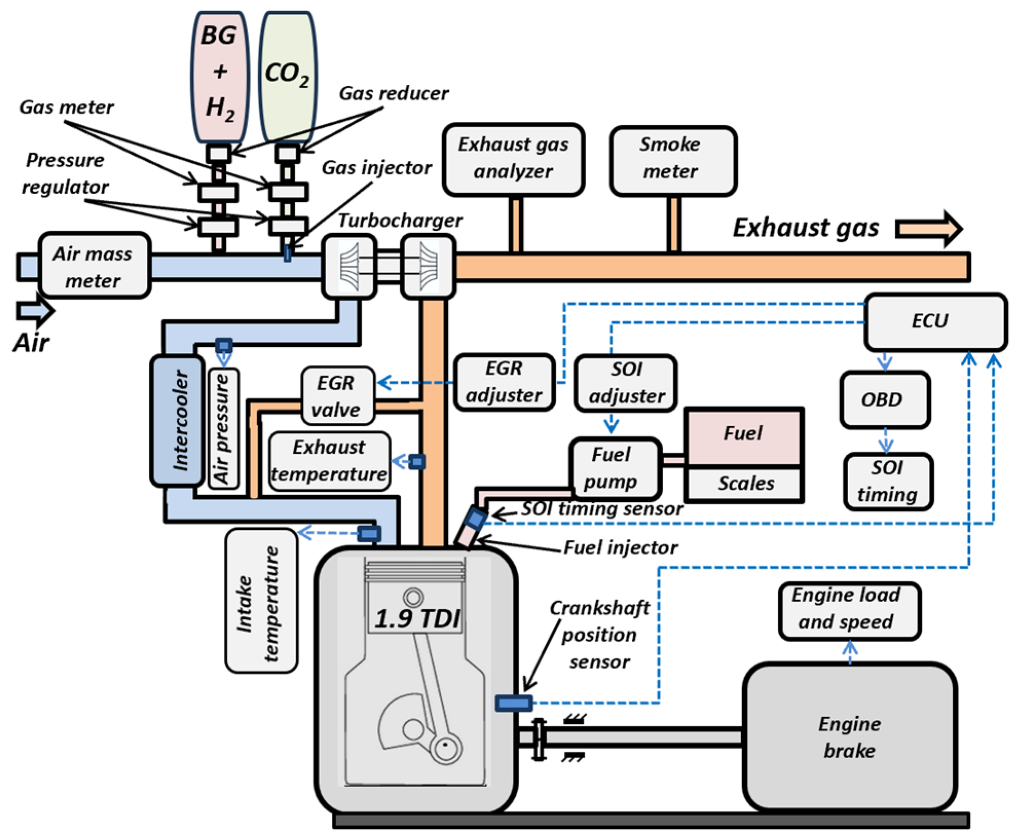
2.1. Experimental Equipment

Experimental tests of a CI-ICE in a dual-fuel mode were carried out on an 1.9 TDI (turbo direct injection) (Audi-VW, Germany) compression ignition engine, and its main technical characteristics are presented in Table 1.
The engine was equipped with an optional Elpigaz-Degamix (ELPIGAZ, Poland) gas injection system, which received relevant information from the CI-ICE’s electronic control unit (ECU). The engine parameters were measured by loading the engine with an electric motor. Fuel consumption was measured by the gravity method, intake manifold pressure was measured by an additional pressure meter, and intake air and exhaust air temperatures were measured by additional temperature sensors. The mass flow rate of the intake air was measured using an additional meter. Cylinder pressure was sensed using a pressure sensor mounted in place of the glow plug and a crankshaft encoder. The cylinder pressure per cycle was determined by measuring 100 working cycles and processing the information with LabView Real Time equipment equipment (National Instrumens, USA). Average pressure values at various CADs were determined. Engine coolant temperature, speed, start of fuel injection, and other CI-ICE parameters were determined using VAG-Com on-board diagnostics (OBD) equipment. A diagram of the engine test equipment is shown in Figure 1, and the main technical characteristics of the equipment used are given in Table 2.
The experimental research was carried out with the CI-ICE running at 2000 rpm because this is the most efficient mode of operation and the one with the highest torque (Table 1). The brake torque of the engine was chosen to be 90 Nm, which corresponds to a BMEP = 0.6 MPa (mean load). In the D-F mode, the energy from the gaseous fuel causes the engine ECU to reduce the cyclical amount of liquid fuel injected by the diesel supply system while at the same time delaying the fuel injection. In order to objectively assess the combustion process, SOI = 8 CAD bTDC was fixed for all fuels that were used. This was achieved by disconnecting the fuel distribution pump from the ECU and generating a control signal for a specific pump charge factor using a control signal modulator. Using the OBD unit VAG-Com, the ECU received data feedback from the OBD unit on the actual start of the fuel injection. The ECU received this information from the fuel injector needle sensor.
The experimental tests were repeated at least five times to ensure the reproducibility of the results. The result of a single test with the closest value to the average of all tests was used to analyze the combustion process.

2.2. Fuels and Blends

During the test, the engine was run on a variety of fuel mixtures. In the first stage, the test was carried out with pure diesel (D100), in the second stage, pure biodiesel (HVO100) was used, and in the following stages, different dual fuel blends were used in different configurations. In all D-F cases, the pilot biodiesel HVO100 was used for gas ignition. Various blends with HVO100 were used: natural gas (HVO_NG), biogas (HVO_BG), and mixtures of biogas and hydrogen (HVO_BG+H2). The simulated BG produced by mixing NG (~97% CH4 composition) and CO2 gases was used for the test. NG accounted for 60% and CO2 for 40% of the gas volume share (GVS). For the BG and H2 mixtures, the fraction of H2 added to NG was 10%, 20%, and 30% of the NG+H2 volume, or 6%, 12%, and 18% of the GVS. The main physical and chemical properties of the pure fuels are given in Table 3 [38,39]. Considering the volumes and densities of NG and H2, the mass fraction of H2 was calculated to be 1.37%, 3.02%, and 5.07%, respectively.
By measuring the mass flow rates of the individual fuel types and estimating their LHV, the energy input flow of each component to the engine was determined. By measuring the mass flow rates of the individual fuel types and estimating their LHV, the energy input flow of each component to the engine was determined. Experimental studies were carried out for all D-F cases to determine the energy share (ES) of liquid fuel at 60%, 40%, and 20% and the gas energy share (GES) at 40%, 60%, and 80%, respectively. The fuel labelling and composition are presented in Table 4.

2.3. Numerical Analysis Methodology for Combustion

The numerical analysis of the combustion process was carried out using the AVL BOOST software tool BURN (AVL, Austria). The software evaluated the main geometric parameters of the engine (cylinder diameter, piston stroke), the ratio of the crankshaft crank to the connecting rod length, the compression ratio, and others. Also, the physico-chemical properties of the fuels or fuel blends were described. The combustion process parameters were calculated based on experimental data such as the engine speed, load, recorded in-cylinder pressure over the engine cycle, fuel mass and air mass consumption, remaining exhaust gas fraction, turbocharger pressure, and other data. The AVL software used the Woschni 1978 heat transfer mathematical model.
The calculation of the thermodynamic state of the cylinder was based on the 1st law of thermodynamics:
d m c · u d α = p c · d V d α + d Q F d α d Q w d α h B B · d m B B d α + d m i d α · h i d m e d α · h e q e v · f · d m e v d t
The variation in the mass in the cylinder was calculated from the sum of the in-flowing and out-flowing masses:
d m c d α = d m i d α d m e d α d m B B d α + d m e v d t
where:
d m c · u d α change in the internal energy in the cylinder;
p c · d V d α piston work;
d Q F d α fuel heat input;
d Q w d α wall heat losses;
h B B · d m B B d α enthalpy flow due to blow-by;
m c mass in the cylinder;
u specific internal energy;
p c cylinder pressure;
V cylinder volume;
Q F fuel energy;
Q w wall heat loss;
α crank angle;
h B B enthalpy of blow-by;
d m B B d α blow-by mass flow;
d m i mass element flowing into the cylinder;
d m e mass element flowing out of the cylinder;
h i enthalpy of the in-flowing mass;
h e enthalpy of the mass leaving the cylinder;
q e v evaporation heat of the fuel;
f fraction of evaporation heat from the cylinder charge;
m e v mass of evaporating fuel.
The numerical analysis of the combustion process allowed for the determination of the dependence of the mass burned fraction (MBF), the rate of heat release (ROHR), temperature rise, temperature, and pressure rise in the cylinder on the crankshaft rotation angle. From the graphical dependencies developed, the ID, premixed combustion phase, diffusion combustion phase, and later combustion phase and their duration could be determined with reasonable accuracy. The combustion process was evaluated on the basis of these parameters. The AVL BOOST software (AVL, Austria) also allowed for the simulation of the combustion process by calculating the heat release during combustion. The Vibe function is commonly employed to estimate the real heat release characteristics of an engine:
d x d α = a Δ α c · m + 1 · y m · e a · y m + 1
d x = d Q Q
y = α α 0 Δ α c
Q total fuel heat input;
α crank angle;
α 0 start of combustion;
Δ α c combustion duration;
m shape parameter;
a Vibe parameter, typically a = 6.9 for complete combustion.
The integral of the Vibe function gives the fraction of the fuel mass that has burned since the start of combustion:
x = d x d α · d α = 1 e a · y m + 1 ;
x mass fraction burned.
The combustion process was simulated using the parameters set by the BURN software tool (AVL, Austria). For this purpose, a model of the engine under study was created in AVL BOOST, replicating as closely as possible the design of the engine (e.g., valve phasing and opening, cylinder parameters, mechanical losses, intake and exhaust manifold volumes, pipe lengths and diameters, turbocharger parameters, and other parameters). The simulations of the heat release, cylinder pressure and other combustion parameters, engine torque, and power were compared with experimental data and validated. A positive result confirmed an accurate analysis of the combustion process.
Information on the excess air coefficient (λ) and the temperature of the exhaust gas (Tex) is relevant for the analysis of the combustion process. Tex was measured in the exhaust manifold with a K-type thermocouple mounted behind the exhaust valve. The excess air coefficient was calculated by measuring the intake air mass flow rate (Bair, kg/h) and the fuel mass flow rate (Bf, kg/h) and by estimating the stoichiometric air/fuel ratio l0. Using the D-F mode, the mass flows and l0 for each fuel component were estimated separately.
λ = B a i r B f · l 0 _ 1 + B f _ 2 · l 0 _ 2

3. Results and Discussion

For a detailed analysis of the combustion process, data on the excess air ratio (λ) are essential, as they provide relevant information on the composition of the combustion mixture. In an internal combustion engine, the specifics of the fuel mixture formation and power control lead to a wide range of variation in the excess air ratio (10–1.2), but as the load increases, the mass of fuel per cycle increases and λ decreases [35]. In the experimental study, the parameter λ was calculated by taking into account the mass of the intake air, the mass of the individual D-F components supplied, and their l0 (Equation (7)). The results of the calculations are shown in Figure 2, where it can be seen that λ varied significantly with the engine operating in the same mode and with the fuel composition. The highest excess air ratio (λ = 2.51) was obtained when the engine was running on pure diesel D100. The excess air ratio was slightly reduced with HVO100 (λ = 2.49) due to the increase in the elemental composition of H2 in this fuel (Table 3), which led to a higher l0. When using HVO-NG in the D-F mode and increasing the GES to 40%, 60%, and 80%, the excess air ratio decreased significantly (to 2.27, 2.10, and 1.93, respectively), as stoichiometric combustion of NG required ~17.8% more air due to the increased H2 content of the fuel (Table 3). The excess air ratio also decreased with the use of a gas additive because the gas took up part of the air volume in the cylinder. When the engine was operated in HVO_BG D-F mode, the excess air ratio remained similar to the HVO_NG case.
To imitate BG, NG was mixed with CO2 gas, which is inert and does not participate in combustion but is better at absorbing heat, thus lowering the temperature and increasing the density of the gases in the cylinder. In this way, the CO2 gas occupying a certain volume did not reduce the in-cylinder air filling and excess air ratio when the GES was kept the same. Increasing the biogas gas energy share to 80%, similar to the HVO-NG case, resulted in a reduction in the excess air ratio to λ = 1.95. Under these conditions, increasing the concentration of the H2 additive in the NG to 10% (HVO_BG+H1) did not change λ significantly, but increasing the concentration of H2 to 30% (HVO_BG+H3) resulted in an increase in the excess air ratio to λ = 2.03 (~4%). This was likely due to the reduced fuel mass consumption due to the higher H2 LHV and more efficient combustion. The laminar flammability limit of the lean air/gas mixture was reached at a sufficient gas concentration, i.e., λ ≤ 2.0 for NG and λ ≤ 1.9 for biogas. As the initial combustion temperature rises and the mixture swirls intensely, the flammability limits tend to expand. Combustion intensity increases with gas energy share, but combustion is also affected by CO2 concentration, pressure, turbulence etc. [40]. The addition of H2 extends the flammability limits and increases the velocity due to its low ignition energy and combustion in a leaner air/fuel mixture [41].
The temperature of the exhaust gas Tex (Figure 3) provides important information for analyzing the combustion process. The switch from D100 fuel to HVO100 fuel resulted in a negligible increase in the exhaust gas temperature (from 636 K to 641 K). This was probably due to the slight increase in the volume of these fuels and the longer spray time due to the lower density of HVO. In the case of HVO_NG, increasing the GES to 40%, 60%, and 80% increased Tex to 642 K, 660 K, and 675 K, respectively, while in the case of HVO_BG, Tex reached 659 K, 671 K, and 683 K, which were 2.8%, 4.6%, and 6.5% higher than when using HVO. In the case of the D-F mode, the increase in Tex was due to the slower combustion of the lean gas–air mixture in the premixed combustion and diffusion combustion phases (Figure 5), but the heat release became more intense in the late combustion phase. When using HVO_BG, the combustion was slowed by the CO2 in the biogas. The increased energy released with the combustion products reduced the thermal efficiency of the engine [42,43]. Increasing the H2 addition to the biogas resulted in a clear decrease in Tex due to the increase in the combustion velocity. Comparing HVO_BG with HVO_BG+H3 at 80% GES, the exhaust gas temperature decreased from 683 K to 656 K (~4%).
Figure 4 clearly shows that the cylinder pressure at the end of the compression stroke decreased with increasing GES. When the engine operated on D100 or HVO100 fuel, the compressed fresh air was largely composed of a two-atom gas mixture (N2, O2), and in this case, due to the higher compression ratio of the polytropic index compared to NG or BG, the air pressure in the cylinder at the start of the fuel injection (SOI = 8 CAD BTDC) was the highest and reached 7.19 MPa. When using HVO100, the pressure started to rise earlier at the start of combustion, but at a lower intensity compared to D100, and the maximum pressure in the cylinder was 8.87 MPa for HVO100 and 9.01 MPa for D100. This was due to the higher cetane number of HVO (Table 3), which influenced the shorter ID phase and the lower combustion intensity in the premixed combustion phase. It was noticed that only HVO100 showed a low-degree oscillating trend compared to the other fuel mixtures. Probably, the HVO fuel, with its lower density, viscosity, and higher cetane number, had a smoother combustion phenomenon inside the combustion chamber.
In the D-F mode, either NG or BG were delivered to the engine’s air intake. NG is mainly composed of CH4 (five atoms), while biogas is composed of a mixture of CH4 and CO2 gas (five and three atoms). Gases with more atoms in their molecules require more energy to compress and have a lower polytropic index compared to two-atom gases [44,45,46]. Therefore, when increasing the GES up to 40%, the pressure at the end of the compression decreased to ~7.01 MPa (−2.5%); for GES 60%, it decreased to ~6.82 MPa (−5.1%); and for GES 80%, it decreased to ~6.65 MPa (−7.5%). This is one of the reasons why the maximum combustion pressure in the cylinder decreased with increasing the GES. The other two main reasons affecting the in-cylinder pressure during combustion were the decreasing liquid fuel content and the significantly lower combustion intensity of the lean air–gas mixture when the methane flammability limit was exceeded [47]. BG burns even more slowly compared to NG, resulting in an even lower maximum combustion pressure, with a maximum pressure of 7.92 MPa for 20HVO_80BG and 8.03 MPa for 20HVO_80NG, at 10.7% and 9.5% lower, respectively, compared to HVO100. When H2 was added to the biogas, it was observed that at the start of combustion, H2 even reduced the pressure compared to HVO_BD combustion. The expected reason for this pressure drop due to the addition of H2 is the slow combustion of H2 due to the lean mixture and the lower H2 combustion temperature. Only when the H2 concentration was increased to the maximum (20HVO_80(BG+H3)) did the pressure increase.
One of the most important indicators required to objectively analyze the combustion process in an engine cylinder is the rate of heat release (ROHR). The combustion heat release intensity of the tested fuels was determined using the values measured during the experiment (BMEP, cylinder pressure, fuel consumption, air consumption, fuel properties, etc.) and using the AVL BOOST software tool BURN (AVL, Austria). In order to objectively compare the combustion performance of the conventional versus the alternative fuels and the fuel composition, a constant engine load (BMEP = 0.6 MPa), speed (n = 2000 rpm), and start of fuel injection (SOI = 8 CAD BTDC) were ensured. The cylinder pressure graphs (Figure 4) show that at this SOI, the maximum pressure was reached between 7 and 12 CAD after TDC, which ensured efficient engine operation over the entire tested range of fuels. In the D-F mode, it was necessary to force the SOI to be recorded by ignoring the ECU, as increasing the gas energy share caused the engine’s ECU to delay the SOI due to the cyclical reduction in liquid fuel. The delayed start of combustion in the case of the slow combustion of the lean air–gas mixtures significantly reduced the energy efficiency of the engine.
Analysis of the ROHR graphs (Figure 5) shows that the D100 fuels had a later start of combustion (SOC ≈ 1.4 CAD BTDC) compared to HVO100 (SOC ≈ 2.1 CAD BTDC). The shorter ID of HVO100 was caused by the higher cetane number of HVO and the better atomization and evaporation due to its lower density and viscosity [44,48,49,50]. The shorter HVO ID phase and the lower cyclic fuel amount during this period resulted in a ~30% reduction in the maximum ROHR in the premixed combustion phase for HVO100 compared to D100 with ROHR ≈ 31 J/CAD. For all D-F cases, the shorter ID of HVO100 had a positive effect on the earlier gas ignition, as it partially compensated for the slower gas combustion [42,51].
With a gas energy share of 40%, the ROHR in the premixed combustion phase increased slightly as both the liquid and gas were burned together but remained lower compared to D100. By increasing the gas energy share to 80%, the ROHR in the premixed combustion phase decreased as the fuel cycling portion was reduced by ~80%, and the combustion velocity of the lean air–gas mixture was slower after the end of the diesel fuel combustion [52,53,54,55,56,57]. In this combustion phase, the ROHR difference between HVO_NG and HVO_BG was not significant. The addition of H2 to the biogas was expected to increase the ROHR in the premixed combustion phase, but a decrease in the ROHR was observed for 20HVO_80(BG+H3). This can be explained by the slow combustion of the gas due to the lean mixture and the lower combustion temperature of H2.
A maximum ROHR value of ~42 J/CAD (11 CAD after TDC) was achieved in the diffusion combustion phase when engine operated on D100. HVO100 provided a ~2% reduction in the maximum ROHR due to the ~7.2% lower density of this fuel compared to D100 as well as the longer injection time of HVO100 and the slower heat release during combustion. By increasing the GES up to 60%, the maximum ROHR in the diffusion combustion phase decreased to 35-34 J/CAD (~18%) for all gases, reaching the maximum value for 40HVO_60NG. Increasing the GES to 80% resulted in a slight decrease in the maximum ROHR (up to 32 J/CAD) compared to 60% GES, which was reached later (12–14 CAD after TDC). This shows that by increasing the GES to 80% and decreasing the excess air ratio to λ = 1.95, the flammability limit of the gas was reached, and the combustion intensity increased during the diffusion combustion phase. In this case, the maximum ROHR (~34 J/CAD) was reached when the engine operated at 20HVO_80(BG+H3) because the H2 concentration reached a sufficient threshold to increase the combustion rate. Using 20HVO_80BG, the maximum ROHR was the lowest (~31 J/CAD), and the combustion was shifted to the later combustion phase due to the effect of CO2 heat absorption, the lower flammability limits of the biogas, and the flame speed [40,58].
The pressure rise in the cylinder depends on the ID, ROHR, combustion temperature rise, combustion volume, heat exchange, fuel mixture composition, and other factors [44]. The AVL BOOST (AVL, Austria) software showed that when the D100 fuel was replaced with HVO100, the pressure rise in the premixed combustion phase decreased from 0.19 MPa/CAD to 0.12 MPa/CAD (~38%) due to the shorter ID (Figure 6). This reduced the load on the engine crankshaft. With the dual HVO and gas fuels, the pressure rise in the premixed combustion phase exceeded that of pure HVO because the gas started to burn together with the injected liquid fuel. At 40–60% GES, higher pressure rise values at the start of combustion were achieved with the BG+H blends, but at 80% GES, the pressure rise was more intense with NG as the flammability limit of the gas was reached. However, in all D-F cases, the pressure rise in the premixed combustion phase did not exceed the D100 value. The maximum pressure rise in the diffusion combustion phase was similar for the D100 and HVO100 fuels at 0.13 MPa. With the D-F mode and with increasing the gas energy share from 40% to 80%, the pressure rise in the diffusion combustion phase decreased because the gas combustion was not intense due to the lean mixture. Only at the end of the diffusion combustion phase and in the late combustion phase was it observed that increasing the GES up to 80% increased the intensity of gas combustion. In this stage, the maximum pressure rise was achieved by increasing the H2 addition.
The temperature rise in the premixed combustion phase decreased from 43 K/CAD to 30 K/CAD (~30%) when D100 was replaced with HVO100 (Figure 7), because HVO had a shorter ID and a lower ROHR at the start of combustion due to its higher cetane number (Table 3). When the engine was operated in the D-F mode using a mixture of BG and H2 gases with a GES of 40–60%, the temperature rise at the start of combustion rose to 35–37 K/CAD but remained ~15% lower compared to D100. The temperature rise increased because the HVO combustion is accompanied by the combustion of gases, which is more intense when H2 is added. The situation changed when the GES was increased to 80%. In this case, the temperature rise in the premixed combustion phase was reduced due to the reduced cyclic content of the liquid fuel for pilot ignition and the early end of injection and combustion, while the lean air–gas mixture did not burn intensely at the start of combustion [40,59].
The temperature rise in the diffusion combustion phase after the replacement of D100 with HVO100 was similar, with a maximum value of 45 K/CAD (7 CAD after TDC). In the case of the D-F mode and 40% gas energy share, the injection intensity of the liquid fuel remained similar at the start of combustion, and, in combination with the liquid fuel and the slow burning of the gas, a peak temperature rise close to that of the HVO100 case was reached. After the crankshaft moved more than 8 CAD after TDC, the temperature rise decreased compared to HVO100 as the combustion of the liquid fuel ended, but from ~17 CAD after TDC, the temperature rise was higher, indicating a late combustion of the gas. Increasing the gas energy share to 60% and 80% decreased the maximum temperature rise by ~12% and ~25% as the combustion of liquid fuels ended even earlier and the combustion intensity of gas was lower, especially in the case of NG compared to BG, due to the suppressed CO2 effect [52]. However, in the case of 20HVO_80(BG+H3), a higher temperature rise was observed at 12 CAD after TDC and also at the end of the diffusion combustion phase, which indicates that the mixture of BG and H2 reached the intense flammability limit.
The compressed air temperature at the end of compression reached 970 K when the engine was running on the D100 and HVO100 fuels, and it dropped to ~952 K, ~947 K, and 942 K (~1.9%, ~2.4%, and ~2.9%) when the D-F mode was used and the GES was increased up to 40%, 60%, and 80% (Figure 8). The temperature decrease was due to the added supply of either NG or BG to the air, as more energy was used to compress the mixture of these gases with air [44,45,46]. The reason for this is that the NG and BG molecules are composed of more atoms and have a lower polytropic index compared to the two-atom air (N2 and O2) gases.
At high temperatures and pressures in the cylinder, knocking can occur at the end of compression and at the start of combustion when the hydrogen concentration reaches the flammable limit. This requires good engine cooling and efficient intercooler operation. Uncooled EGR gas can increase the chance of knocking by reducing excess air and additionally increasing the temperature in the cylinder. The use of hydrogen in combination with biogas has a positive effect because the CO2 in the biogas performs the EGR effect but prevents H2 from knocking.
The maximum temperature in the combustion chamber (1588 K at 21 CAD after TDC) was reached when the engine was running on the D100 fuel. With HVO100, the maximum temperature at 22 CAD after TDC was 1562 K (~1.6% lower) because HVO has a higher cetane number, which reduced the ROHR in the premix combustion phase. Due to the slower combustion of the gas under lean conditions, HVO_NG had a peak temperature of 1559 K at 23 CAD after TDC for 40% GES, 1543 K at 26 CAD after TDC for 60% GES, and 1511 K at 26 CAD after TDC for 80% GES (~3.3% less than for HVO100). When the engine was operated in the D-F mode with HVO_BG and the GES was increased, the maximum temperature in the cylinder was reduced by an additional 0.6%-1.2% compared to HVO_NG due to the CO2 suppression effect. A more noticeable effect of the increase in the maximum temperature due to the use of H2 was only observed at 80% GES with the maximum H2 additive in the biogas (20HVO_80(BG+H3)), in which case, the temperature in the cylinder reached 1535 K (1.6% increase compared to 20HVO_80BG).
Figure 9 shows the combustion process abstraction rates (expressed in CAD): (a) ignition delay; (b) 10% of the fuel mass burnt (MBF10); (c) 50% of the fuel mass burnt (MBF50); and (d) 90% of the fuel mass burnt (MBF90). For all fuels, the start of fuel injection was SOI = 8 CAD BTDCD. The change from D100 to HVO100 due to the higher cetane number shortened the ID from 6.6 CAD to 5.9 CAD and reduced the ROHR, pressure rise, and temperature rise in the premix combustion phase. When using HVO_NG in the D-F mode, the ID increased slightly (up to 6.1 CAD) at a GES of 40%, but when increasing the GES up to 80%, it became the same as for HVO100. This shows that the NG had little effect on the ID. When using HVO_BG in the D-F mode, the ID increased (up to 6.6 CAD) at a GES of 40% and decreased to 6.3 CAD when increasing the GES to 80%. This shows that the effect of the CO2 in the biogas was to suppress ignition, but this effect declined as the GES and excess air ratio increased and the flammability limit was approached. When using BG with H2 additive, it was observed that the H2 effectively shortened the ID prolongation due to the BG, and in the case of 20HVO_80(BG+H3), the ID became similar to that of HVO100. The reduction in ID was probably due to two reasons: (1) reduced excess air due to the increase in GES, which reduced the amount of air in the cylinder; and (2) the increase in the hydrogen concentration in the biogas and the reduction in excess air allowed the H2 to reach closer to the flammability limit.
The start of combustion was the most intense with HVO100 (MBF10 ≈ 4.9 CAD), which had a lower density and viscosity due to its higher H2 content and lower molecular structure, and which was more easily sprayed, evaporate, and starts combustion earlier compared to D100 [44,48,49,50], which had an MBF10 ≈ 5.1 CAD. Using the D-F mode and increasing the GES to 80%, the MBF10 increased to ~5.7 CAD for NG and ~6.5 CAD for BG, which was ~32% higher compared to HVO100. This was influenced by the later start of combustion and the content of CO2 in the BG, which inhibited not only the ignition but also the start of combustion. The H2, by increasing its concentration in the biogas, helped to shorten both the ID and MBF10 due to its easier ignition and higher combustion rate, but it was observed that by increasing the GES up to 80% and by using a H2 additive, the effect of accelerating the combustion at the initial stage of combustion was not significant. In the case of 20HVO+80(BG+H3), MBF10 ≈ 6.1 CAD, and it remained ~24% higher compared to HVO100.
The MBF50 value indicates when 50% of the fuel mass is burnt, and it is important that this value should be reached at the optimum time for the maximum thermal efficiency of the engine. The ROHR during the diffusion combustion phase depends on this value. The MBF50 value was the same for the D100 and HVO100 fuels at 13.4 CAD (Figure 9). In the D-F mode, when either NG or BG were added, the combustion intensity decreased due to the lean mixture and the unreached flammability limit, and when the GES reached 80%, the MBF50 value reached ~15.5 CAD and ~16.1 CAD, respectively. The addition of H2 to the BG decreased the MBF50 value, and in the case of HVO_BG+H3, the combustion intensity was close to that of the HVO_NG dual fuels because the H2 compensated for the combustion inhibition effect of the CO2.
H2 accelerates the combustion of biogas during the diffusion combustion phase as the more intense combustion is shifted to the later combustion phase, which can be partly assessed by MBF90 analysis [44]. The MBF90 increased from 31.0 CAD to 31.6 CAD when D100 is replaced by HVO 100 because HVO fuels are lower in density and take longer to inject. This also extended the combustion time, as evidenced by the higher Tex of HVO100 compared to D100 (Figure 3). In the case of the D-F mode, increasing the GES did not lead to a single trend in the MBF90 indicator. Increasing the GES to 60% increased the MBF90 to 32.6 CAD for NG and 33.7 CAD for BG because the air–gas mixture had not yet reached the flammability limit. At 80% GES, the MBF90 increased a little further (to 32.7 CAD and 34.1 CAD, respectively) because the excess air ratio approached the flammability limit (Figure 2). With increasing the H2 addition to the BG, the MBF90 gradually decreased, to 32.8 CAD for 20HVO_80(BG+H3) (~4% less than 20HVO_80BG).
A higher contribution of the H2 to the reduction in the biogas combustion time was expected, but as the H2 concentration increased, the excess air ratio increased and moved away from the BG flammability limit, which did not allow for a significant increase in the gas burning velocity. The excess air ratio increased because the LHV of H2 is ~6.2 times that of BG, and the addition of H2 reduces the mass of the fuel mixture, while the mass of air required to burn 1 kg of H2 is only ~2.4 times greater than the mass of air required for the stoichiometric combustion of BG (Table 3). In the case of HVO_BG, the use of H2 additive was not sufficient to effectively improve the combustion of BG, but at the same time, the GES must be increased, and the excess air ratio must be reduced in order to reach the flammability limit not only for H2 but also for BG. In the case of HVO_NG, the flammability limit was reached at a leaner air–fuel mixture, in which case, efficient combustion could be achieved in the D-F mode without H2 additive.

4. Conclusions

The experimental studies of a CI-ICE operating at a medium load and speed and using HVO_BG+H2 in the D-F mode determined the indicators of the combustion process by varying the GES and H2 concentration. The results of the CI-ICE running on HVO_BG+H2 compared to the results of liquid fuel (D100, HVO100) and D-F (HVO_NG) were as follows:
(1)
Increasing the GES to 80% (in the case of 20HVO_80BG) decreased the excess air ratio from 2.49 (HVO100) to λ = 1.95 and brought it closer to the flammability limit of biogas (λ = 1.90). Increasing the H2 concentration to 30% of the volume of methane in the biogas (20HVO_80(BG+H3)) increased the excess air ratio to λ = 2.03, but the better flammability properties of H2 extended the flammable limit of the mixture.
(2)
In the case of the D-F mode, by compressing the air with NG or BG additive and increasing the GES to 40%, 60%, and 80%, the pressure at the end of the compression stroke decreased by ~2.5%, ~5.1%, and ~7.5%, respectively, because the air composed of two-atom molecules (N2, O2) was partially replaced by four-atom molecules (CH4) and three-atom molecules (CO2), which have a lower compressibility polytropic index. The increased energy demand for the compression of NG and biogas also reduced the temperature at the end of the compression and caused a deterioration in the ignition conditions of the pilot fuels.
(3)
HVO100 fuels have a higher cetane number compared to D100 due to their altered chemical–physical properties (higher H/C ratio, better atomization and vaporization, etc.), which shortens the ID phase. HVO100 is therefore better suited as a pilot fuel in the D-F mode, especially when using BG, as it partially compensates for the slower combustion.
(4)
As the GES was increased, the ROHR of combustion during the premixed combustion phase increased slightly as the combustion of the liquid fuel was simultaneously accompanied by the combustion of the gas. Increasing the H2 addition to the biogas further did not increase the ROHR in this combustion phase, because the mixture was extremely lean at the start of combustion and the gas burned at a low velocity. In the second phase, diffusion combustion, the ROHR decreased as the GES increased to 80% because the HVO injection and combustion ended earlier due to the reduction in the pilot fuel, and the combustion of gases, in particular BG, was slower. However, in this phase, the addition of H2 to the BG already had a positive combustion velocity enhancement effect because the excess air from the combustion was reduced and the pressure and temperature were increased. The tendency for more intense combustion was repeated in both the pressure rise and temperature rise characteristics.
(5)
The MBF analysis showed that increasing the GES from 40% to 80%, with HVO_NG, increased the duration of the MBF10 and MBF50, indicating slower combustion. However, the duration of the MBF90 did not increase with an increase in the GES from 60% to 80%, and considering that the MBF50 ended later, we can say that in this case, the diffusion combustion phase was shortened due to the faster NG combustion after the flammability limit was reached. When the engine was operated on the HVO_BG dual biofuels, only increasing the H2 addition (up to 30% methane by volume) led to higher combustion speeds and a shortening of the diffusion combustion and later combustion phases. In this case, the addition of hydrogen resulted in the combustion characteristics of HVO_BG being closer to those of HVO_NG. This was confirmed by the decreasing value of Tex, indicating an increase in the thermal efficiency of the combustion process.

Author Contributions

Conceptualization, A.R. and J.Ž.; methodology, A.R. and J.Ž.; software, A.R.; validation, A.R. and J.Ž.; formal analysis, A.R. and J.Ž.; investigation, A.R. and J.Ž.; resources, A.R. and J.Ž.; data curation, A.R.; writing—original draft preparation, A.R. and J.Ž.; writing—review and editing, J.Ž.; visualization, A.R. and J.Ž.; supervision, J.Ž.; project administration, A.R. and J.Ž.; funding acquisition, J.Ž. All authors have read and agreed to the published version of the manuscript.

Funding

This research received no external funding.

Institutional Review Board Statement

Not applicable.

Informed Consent Statement

Not applicable.

Data Availability Statement

Data is contained within the article.

Acknowledgments

This research was conducted as part of the execution of project “Mission-driven Implementation of Science and Innovation Programmes” (No. 02-002-P-0001), funded by the Economic Revitalization and Resilience Enhancement Plan “New Generation Lithuania”. The results of the dual-fuel combustion process analysis presented in this study were obtained using the AVL BOOST internal combustion engine numerical simulation software. This software was obtained under a cooperation agreement between AVL Advanced Simulation Technologies and Vilnius Gediminas Technical University, Faculty of Transport Engineering.

Conflicts of Interest

The authors declare no conflicts of interest.

References

  1. European Union. Directive 2018/2001 on the Promotion of the Use of Energy from Renewable Sources. Available online: https://eur-lex.europa.eu/eli/dir/2018/2001/oj (accessed on 12 August 2024).
  2. European Commission. White Paper 2011: Roadmap to a Single European Transport Area. Available online: https://transport.ec.europa.eu/white-paper-2011_en (accessed on 12 August 2024).
  3. Srivastava, R.; Kumar, R. Advances in the Field of Bioenergy. In Handbook of Bioenergy; Springer: Berlin/Heidelberg, Germany, 2023. [Google Scholar]
  4. Diano, N.; Riccardi, C. Greenhouse Gas Reduction Technologies in Industrial Processes. Chem. Eng. Trans. 2015, 43, 409–414. Available online: https://www.aidic.it/cet/15/43/069.pdf (accessed on 15 August 2024).
  5. Ao, T.-J.; Liu, C.-G.; Sun, Z.-Y.; Zhao, X.-Q.; Tang, Y.-Q.; Bai, F.-W. Anaerobic Digestion Integrated with Microbial Electrolysis Cell to Enhance Biogas Production and Upgrading In Situ. Biotechnol. Adv. 2024, 73, 108372. [Google Scholar] [CrossRef] [PubMed]
  6. Barbusiński, K.; Kalemba, K. Removal of H₂S in Biogas Systems. Arch. Civ. Eng. Environ. 2016, 9, 53–58. [Google Scholar] [CrossRef]
  7. Alrbai, M.; Ahmad, A.D.; Al-Dahidi, S.; Abubaker, A.M.; Al-Ghussain, L.; Hayajneh, H.S.; Akafuah, N.K. Hydrogen Sulfide Impacts in Biogas Combustion. Case Stud. Therm. Eng. 2022, 35, 102509. [Google Scholar] [CrossRef]
  8. Ghimire, A.; Gyawali, R.; Lens, P.N.L.; Lohani, S.P. Technologies for H₂S Removal in Biogas. In Renewable Energy Technologies. Emerg. Technol. Biol. Syst. Biogas Upgrad. 2021, 295–320. [Google Scholar] [CrossRef]
  9. Calbry-Muzyka, A.; Madi, H.; Rüsch-Pfund, F.; Gandiglio, M.; Biollaz, S. Composition Analysis of Agricultural Biogas. Renew. Energy 2022, 189, 1249–1260. [Google Scholar] [CrossRef]
  10. Shin, J.; Kim, W.; Lee, J.M.; Lee, M.J.; Song, H.W.; Kim, S.D. Simultaneous H₂S and Siloxane Removal in Biogas. Detritus 2023, 23, 18276. [Google Scholar] [CrossRef]
  11. Sidi Habib, S.; Torii, S.; Kavitha Mol, S.; Achuthan Nair, A.C. Optimization of the Factors Affecting Biogas Production Using the Taguchi Design of Experiment Method. Biomass 2024, 4, 687–703. [Google Scholar] [CrossRef]
  12. European Commission. Methane Emissions Management in Energy Sector. Available online: https://energy.ec.europa.eu/topics/carbon-management-and-fossil-fuels/methane-emissions_en (accessed on 30 August 2024).
  13. U.S. Environmental Protection Agency (EPA). Understanding Global Warming Potentials. Available online: https://www.epa.gov/ghgemissions/understanding-global-warming-potentials#:~:text=Methane%20(CH4)%20is%20estimated,is%20reflected%20in%20the%20GWP (accessed on 30 August 2024).
  14. Melnyk, O.; Onyshchenko, S.; Onishchenko, O.; Shumylo, O.; Voloshyn, A.; Ocheretna, V.; Fedorenko, O. Implementation Research of Alternative Fuels and Technologies in Maritime Transport. In Green Energy and Technology; Springer: Berlin/Heidelberg, Germany, 2023; Available online: https://link.springer.com/chapter/10.1007/978-3-031-44351-0_2 (accessed on 5 September 2024).
  15. Ramsay, W.; Fridell, E.; Michan, M. Maritime Energy Transition: Future Fuels and Future Emissions. J. Mar. Sci. Appl. 2023, 22, 369–381. Available online: https://link.springer.com/article/10.1007/s11804-023-00369-z (accessed on 5 September 2024). [CrossRef]
  16. Schönsteiner, K.; Massier, T.; Hamacher, T. Sustainable Transport by Use of Alternative Marine and Aviation Fuels: A Well-to-Tank Analysis to Assess Interactions with Singapore’s Energy System. Renew. Sustain. Energy Rev. 2016, 66, 190–202. [Google Scholar] [CrossRef]
  17. Al-Abboodi, N.K.F.; Ridha, H. Design and Thermodynamics Analysis of Marine Dual Fuel Low-Speed Engine with Methane Reforming Integrated High-Pressure Exhaust Gas Recirculation System. Fuel 2022, 324, 123747. [Google Scholar] [CrossRef]
  18. Curran, S.; Onorati, A.; Payri, R.; Agarwal, A.K.; Arcoumanis, C.; Bae, C.; Boulouchos, K.; Chuahy, F.D.F.; Gavaises, M.; Hampson, G.J.; et al. The Future of Ship Engines: Renewable Fuels and Enabling Technologies for Decarbonization. Int. J. Eng. Res. 2023. [Google Scholar] [CrossRef]
  19. Rueda-Vázquez, J.M.; Serrano, J.; Pinzi, S.; Jiménez-Espadafor, F.J.; Dorado, M.P. A Review of the Use of Hydrogen in Compression Ignition Engines with Dual-Fuel Technology and Techniques for Reducing NOx Emissions. Sustainability 2024, 16, 3462. [Google Scholar] [CrossRef]
  20. Feroskhan, M.F.; Ismail, S.; Natarajan, G.; Manavalla, S.; Yunus Khan, T.M.; Abdul Khadar, S.D.; Azam Ali, M. A Comprehensive Study of the Effects of Various Operating Parameters on a Biogas-Diesel Dual Fuel Engine. Sustainability 2023, 15, 21232. [Google Scholar] [CrossRef]
  21. Rimkus, A.; Stravinskas, S.; Matijošius, J. Comparative Study on the Energetic and Ecologic Parameters of Dual Fuels (Diesel–NG and HVO–Biogas) and Conventional Diesel Fuel in a CI Engine. Appl. Sci. 2020, 10, 359. [Google Scholar] [CrossRef]
  22. Harish, H.; Kempaiah, U.N. Experimental Analysis of a CI Engine Running on Dual-Fuel Mode with Gaseous and Liquid Fuels. Int. J. Eng. Res. Technol. 2016, 4, 31013. [Google Scholar]
  23. Zhang, Z.; Lv, J.; Li, W.; Long, J.-X.; Wang, S.; Tan, D.M.; Yin, Z. Performance and Emission Evaluation of a Marine Diesel Engine Fueled with Natural Gas Ignited by Biodiesel-Diesel Blended Fuel. Energy 2022, 256, 124662. [Google Scholar] [CrossRef]
  24. Costa, R.B.R.; Valle, R.M.; Hernández, J.J.; Malaquias, A.C.T.; Coronado, C.J.R.; Pujatti, F.J.P. Experimental Investigation on the Potential of Biogas/Ethanol Dual-Fuel Spark-Ignition Engine for Power Generation: Combustion, Performance and Pollutant Emission Analysis. Appl. Energy 2020, 261, 114438. [Google Scholar] [CrossRef]
  25. Nguyen, V.N.; Nayak, S.K.; Le, H.S.; Kowalski, J.; Deepanraj, B.; Duong, X.Q.; Truong, T.H.; Tran, V.D.; Cao, D.N.; Nguyen, P.Q.P. Performance and Emission Characteristics of Diesel Engines Running on Gaseous Fuels in Dual-Fuel Mode. Int. J. Hydrogen Energy 2024, 49 Pt B, 868–909. [Google Scholar] [CrossRef]
  26. Algayyim, S.J.M.; Saleh, K.; Wandel, A.P.; Fattah, I.M.R.; Yusaf, T.; Alrazen, H.A. Influence of Natural Gas and Hydrogen Properties on Internal Combustion Engine Performance, Combustion, and Emissions: A Review. Fuel 2023, 344, 130844. [Google Scholar] [CrossRef]
  27. Ng, W.C.; Yaw, C.S.; Shaffee, S.N.A.; Samad, N.A.A.; Koi, Z.K.; Chong, M.N. Elevating the Prospects of Green Hydrogen (H₂) Production Through Solar-Powered Water Splitting Devices: A Systematic Review. Sustain. Mater. Technol. 2024, 40, e00972. [Google Scholar] [CrossRef]
  28. Rameez, P.V.; Ibrahim, M.M. A Comprehensive Review on the Utilization of Hydrogen in Low Temperature Combustion Strategies: Combustion, Performance and Emission Attributes. J. Ocean Eng. Sci. 2023, 113, 101511. [Google Scholar] [CrossRef]
  29. Sterlepper, S.; Fischer, M.; Claßen, J.; Huth, V.; Pischinger, S. Concepts for Hydrogen Internal Combustion Engines and Their Implications on the Exhaust Gas Aftertreatment System. Energies 2021, 14, 8166. [Google Scholar] [CrossRef]
  30. Hassan, Q.; Algburi, S.; Sameen, A.Z.; Salman, H.M.; Jaszczur, M. Green Hydrogen: A Pathway to a Sustainable Energy Future. Int. J. Hydrogen Energy 2024, 50, 310–333. [Google Scholar] [CrossRef]
  31. Roque, L.F.A.; da Costa, R.B.R.; de Souza, T.A.Z.; Coronado, C.J.R.; Pinto, G.M.; Cintra, A.J.A.; Raats, O.O.; Oliveira, B.M.; Frez, G.V.; Alves, L.F.R. Experimental Analysis and Life Cycle Assessment of Green Diesel (HVO) in Dual-Fuel Operation with Bioethanol. J. Clean. Prod. 2023, 389, 135989. [Google Scholar] [CrossRef]
  32. Dobrzyńska, E.; Szewczyńska, M.; Pośniak, M.; Szczotka, A.; Puchałka, B.; Woodburn, J. Exhaust Emissions from Diesel Engines Fueled by Different Blends with the Addition of Nanomodifiers and Hydrotreated Vegetable Oil HVO. Environ. Pollut. 2020, 259, 113772. [Google Scholar] [CrossRef]
  33. No, S.-Y. Parffinic Biofuels: HVO, BTL Diesel, and Farnesane. In Advanced Biofuels and Bioproducts; Springer: Berlin/Heidelberg, Germany, 2019. [Google Scholar] [CrossRef]
  34. Ferguson, C.R.; Kirkpatrick, A.T. Internal Combustion Engines: Applied Thermosciences, 3rd ed.; Wiley: Hoboken, NJ, USA, 2015. [Google Scholar]
  35. Smigins, R.; Sondors, K.; Pirs, V.; Dukulis, I.; Birzietis, G. Studies of Engine Performance and Emissions at Full-Load Mode Using HVO, Diesel Fuel, and HVO5. Energies 2023, 16, 4785. [Google Scholar] [CrossRef]
  36. Bullermann, J.; Meyer, N.-C.; Krafft, A.; Wirz, F. Comparison of Fuel Properties of Alternative Drop-In Fuels with Standard Marine Diesel and the Effects of Their Blends. Fuel 2024, 357, 129937. [Google Scholar] [CrossRef]
  37. Sahoo, B.B.; Sahoo, N.; Saha, U.K. Effect of Engine Parameters and Type of Gaseous Fuel on the Performance of Dual-Fuel Gas Diesel Engines—A Critical Review. Renew. Sustain. Energy Rev. 2009, 13, 1151–1184. [Google Scholar] [CrossRef]
  38. Yang, B.; Xi, C.; Wei, X.; Zeng, K.; Lai, M.-C. Parametric Investigation of Natural Gas Port Injection and Diesel Pilot Injection on the Combustion and Emissions of a Turbocharged Common Rail Dual-Fuel Engine at Low Load. Appl. Energy 2015, 143, 130–137. [Google Scholar] [CrossRef]
  39. Khatri, N.; Khatri, K.K. Hydrogen Enrichment on Diesel Engine with Biogas in Dual Fuel Mode. Int. J. Hydrogen Energy 2020, 45, 7128–7140. [Google Scholar] [CrossRef]
  40. Pizzuti, L.; Martins, C.A.; Lacava, P.T. Laminar burning velocity and flammability limits in biogas: A literature review. Renew. Sustain. Energy Rev. 2016, 62, 856–865. [Google Scholar] [CrossRef]
  41. Verma, S.; Das, L.M.; Bhatti, S.S.; Kaushik, S.C. A comparative exergetic performance and emission analysis of pilot diesel dual-fuel engine with biogas, CNG and hydrogen as main fuels. Energy Convers. Manag. 2017, 151, 764–777. [Google Scholar] [CrossRef]
  42. Pinto, G.M.; da Costa, R.B.R.; de Souza, T.A.Z.; Rosa, A.J.A.C.; Raats, O.O.; Roque, L.F.A.; Frez, G.V.; Coronado, C.J.R. Experimental investigation of performance and emissions of a CI engine operating with HVO and farnesane in dual-fuel mode with natural gas and biogas. Energy 2023, 277, 127648. [Google Scholar] [CrossRef]
  43. Verma, S.; Das, L.M.; Kaushik, S.C. Effects of varying composition of biogas on performance and emission characteristics of compression ignition engine using exergy analysis. Energy Convers. Manag. 2017, 138, 346–359. [Google Scholar] [CrossRef]
  44. Heywood, J.B. Internal Combustion Engine Fundamentals, 2nd ed.; McGraw-Hill Education: New York, NY, USA, 2018. [Google Scholar]
  45. Bąkowski, A.; Radziszewski, L.; Milan, Ž. Determining the Polytrophic Exponent of the Process Occurring During the Working Cycle of a Diesel. Procedia Eng. 2016, 136, 220–226. [Google Scholar] [CrossRef]
  46. Lee, Y.; Min, K. Estimation of the polytropic index for in-cylinder pressure prediction in engines. Appl. Therm. Eng. 2019, 158, 113703. [Google Scholar] [CrossRef]
  47. Kubica, G.; Flekiewicz, M.; Marzec, P. Selected aspects of the use of gaseous fuels blends to improve efficiency and emission of SI engine. Transp. Probl. 2019, 14, 95–103. [Google Scholar] [CrossRef]
  48. Han, J.; Wang, Y.; Somers, L.M.T.; van de Beld, B. Ignition and combustion characteristics of hydrotreated pyrolysis oil in a combustion research unit. Fuel 2022, 316, 123419. [Google Scholar] [CrossRef]
  49. Marasri, S.; Ewphun, P.-P.; Srichai, P.; Charoenphonphanich, C.; Karin, P.; Tongroon, M.; Kosaka, H. Combustion Characteristics of Hydrotreated Vegetable Oil-Diesel Blends under EGR and Low Temperature Combustion Conditions. Int. J. Automot. Technol. 2019, 20, 569–578. [Google Scholar] [CrossRef]
  50. Parravicini, M.; Barro, C.; Boulouchos, K. Experimental characterization of GTL, HVO, and OME based alternative fuels for diesel engines. Fuel 2021, 292, 120177. [Google Scholar] [CrossRef]
  51. Rahman, K.A.; Ramesh, A. Studies on the effects of methane fraction and injection strategies in a biogas diesel common rail dual fuel engine. Fuel 2019, 236, 147–165. [Google Scholar] [CrossRef]
  52. Swami Nathan, S.; Mallikarjuna, J.M.; Ramesh, A. An experimental study of the biogas–diesel HCCI mode of engine operation. Energy Convers. Manag. 2010, 51, 1347–1353. [Google Scholar] [CrossRef]
  53. Bora, B.J.; Saha, U.K. Optimisation of injection timing and compression ratio of a raw biogas powered dual fuel diesel engine. Appl. Therm. Eng. 2016, 92, 111–121. [Google Scholar] [CrossRef]
  54. Bora, B.J.; Saha, U.K. Experimental evaluation of a rice bran biodiesel—Biogas run dual fuel diesel engine at varying compression ratios. Renew. Energy 2016, 87, 782–790. [Google Scholar] [CrossRef]
  55. Bora, B.J.; Saha, U.K. Theoretical Performance Limits of a Biogas–Diesel Powered Dual Fuel Diesel Engine for Different Combinations of Compression Ratio and Injection Timing. J. Energy Eng. 2016, 142. [Google Scholar] [CrossRef]
  56. Bora, B.J.; Saha, U.K. Comparative assessment of a biogas run dual fuel diesel engine with rice bran oil methyl ester, pongamia oil methyl ester and palm oil methyl ester as pilot fuels. Renew. Energy 2015, 81, 490–498. [Google Scholar] [CrossRef]
  57. Talibi, M.; Hellier, P.; Ladommatos, N. Combustion and exhaust emission characteristics, and in-cylinder gas composition, of hydrogen enriched biogas mixtures in a diesel engine. Energy 2017, 124, 397–412. [Google Scholar] [CrossRef]
  58. Park, O.; Veloo, P.S.; Liu, N.; Egolfopoulos, F.N. Combustion characteristics of alternative gaseous fuels. Proc. Combust. Inst. 2011, 33, 887–894. [Google Scholar] [CrossRef]
  59. Pham, Q.; Park, S.; Agarwal, A.K.; Park, S. Review of dual-fuel combustion in the compression-ignition engine: Spray, combustion, and emission. Energy 2022, 250, 123778. [Google Scholar] [CrossRef]
Figure 1. The arrangement of experimental setup.
Jmse 12 02192 g001
Figure 2. Change in excess air ratio with change in fuel composition.
Jmse 12 02192 g002
Figure 3. Change in exhaust gas temperature with change in fuel composition.
Jmse 12 02192 g003
Figure 4. Cylinder pressure variation with changing fuel composition for gas energy share of (a) 40%, (b) 60%, and (c) 80%.
Jmse 12 02192 g004
Figure 5. Rate of heat release when varying fuel composition for gas energy share of (a) 40%, (b) 60%, and (c) 80%.
Jmse 12 02192 g005
Figure 6. Pressure rise in the cylinder with different fuels for gas energy share of (a) 40%, (b) 60%, and (c) 80%.
Jmse 12 02192 g006
Figure 7. Temperature rise in the cylinder using different fuels for gas energy share of (a) 40%, (b) 60%, and (c) 80%.
Jmse 12 02192 g007
Figure 8. Temperature in cylinder using different fuels for gas energy share of (a) 40%, (b) 60%, and (c) 80%.
Jmse 12 02192 g008
Figure 9. Combustion duration using different fuels for (a) ignition delay, and fuel mass burnt fraction of (b) 10%, (c) 50%, and (d) 90%.
Jmse 12 02192 g009aJmse 12 02192 g009b
Table 1. Key technical characteristics of the CI-ICE Audi-VW 1Z 1.9 TDI.
ParameterValue
Number of cylinders4
Displacement (cm3)1896
Bore/stroke, mm79.5/95.5
Compression ratio19.5
Power 66 kW (at 4000 rpm)
Torque 180 Nm (at 2000–2500 rpm)
AspirationTurbocharger
Fuel injection Direct injection (single)
Camshaft locationOverhead camshaft engine (OHC)
Table 2. Key characteristics of CI-ICE test equipment.
EquipmentIndicator, UnitsMeasurement RangeAccuracy
Engine load bench KI-5543 (GOSNITI, Russia)MB, Nm0–440 ±1.2 Nm
Electronic fuel scales SK-5000 (A&D, Germany)Bf, kg0–5.0±1.0 g
Air mass meter BOSCH HFM 5 (BOSCH, Germany)Bair, kg/h8–370±2%
Gas mass flow meter RHM 015 (RHEONIK, Germany)Bgas, kg/h0.09–36±0.1%
In-cylinder pressure piezoelectric sensor AVL GH13P (AVL, Austria)pc, bar0–250Sensitivity 15.84 ± 0.09 pC/bar
Crankshaft encoder A58M-F (Precizika Metrology, Lithuania)CAD0–360Repeatability 0.176 CAD
Pressure meter Delta OHM HD 2304.0/TP704-5BAI (Delta Ohm, Italy)PTC, bar0–360±0.4%
Temperature sensor (K-type thermocouple) (Cartridge Heaters, United Kingdom)Tex, °C0–1200±1.5° C
SOI measurement equipment VAG-Com (Ross-Tech, Germany)SOI, CAD bTDC0–20±1.0°CAD
Table 3. Physical and chemical properties of fuels.
TitleD100HVO100NGBGH2
Lower heating value LHV, MJ/kg42.543.6348.6~19.2120
Density, 15 °C, kg/m38407800.722~1.20.09
Cetane number52.174.3---
Octane number--130120130
Elemental composition, C %8784.775-0
Elemental composition, H %1315.325-100
Stoichiometric air/fuel ratio lo, kg/kg14.615.117.2~6.234.8
Table 4. Labeling and structure of fuel mixtures.
TitleD
(ES)
HVO
(ES)
GAS
(GES)
NG
(GVS)
CO2
(GVS)
H2
(GVS)
D100100%-----
HVO100-100%----
60HVO_40NG-60%40%100%--
60HVO_40BG-60%40%60%40%-
60HVO_40(BG+H1)-60%40%54%40%6%
60HVO_40(BG+H2)-60%40%48%40%12%
60HVO_40(BG+H3)-60%40%42%40%18%
40HVO_60NG-40%60%100%--
40HVO_60BG-40%60%60%40%-
40HVO_60(BG+H1)-40%60%54%40%6%
40HVO_60(BG+H2)-40%60%48%40%12%
40HVO_60(BG+H3)-40%60%42%40%18%
20HVO_80NG-20%80%100%--
20HVO_80BG-20%80%60%40%-
20HVO_80(BG+H1)-20%80%54%40%6%
20HVO_80B(G+H2)-20%80%48%40%12%
20HVO_80B(G+H3)-20%80%42%40%18%
Disclaimer/Publisher’s Note: The statements, opinions and data contained in all publications are solely those of the individual author(s) and contributor(s) and not of MDPI and/or the editor(s). MDPI and/or the editor(s) disclaim responsibility for any injury to people or property resulting from any ideas, methods, instructions or products referred to in the content.

