1. Introduction
In-line tensioning technology has gained prominence in the floating offshore industry due to its notable cost-effectiveness. Wind energy, as an enduring and eco-friendly source of clean energy, is increasingly being adopted globally because of its vast potential and diverse technological applications. By 2030, the total capacity of offshore wind power is projected to reach 380 GW, escalating to 2000 GW by 2050 [
1]. However, the high costs associated with FOWTs pose substantial barriers to their large-scale development. Mooring tensioning systems, a primary cost component for both capital expenditures (CAPEX) and operational expenditures (OPEX), facilitate the deployment of FOWTs far from shorelines and are not limited by water depth [
2,
3]. Furthermore, Yang et al. [
4] highlighted that, compared to traditional marine petroleum exploitation, the equipment used in floating wind power platforms entails lower risks post-failure and reduced requirements for equipment redundancy, thus supporting the potential application of in-line tensioning technology.
The concept of in-line tensioning was initially introduced in a 2006 patent application by Dove et al. [
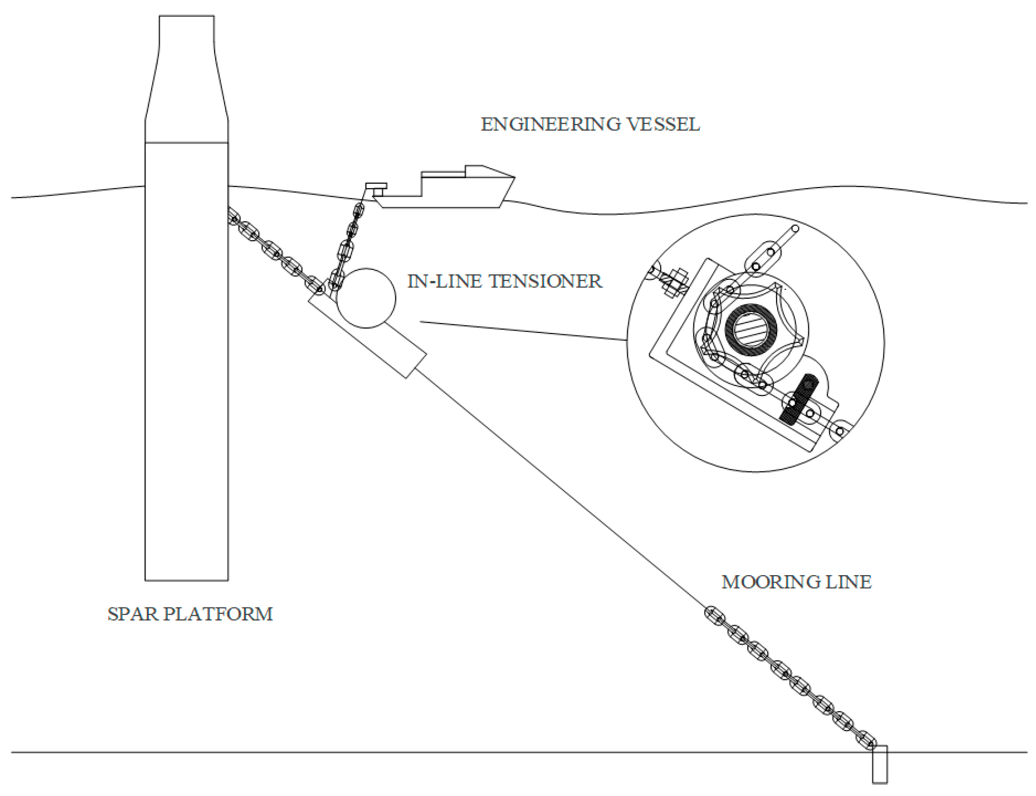
5], representing a breakthrough in mooring system design. As shown in
Figure 1, this new type of mooring tensioning equipment can replace traditional systems on mooring platforms, offering a more convenient tensioning operation while significantly improving cost-effectiveness, with the ability to achieve required tensioning capabilities. Characterized by a sprocket and a retaining device within a frame structure, in-line tensioners function through an engineering ship’s lifting system, which pulls the chain’s free end to achieve tension. This method, enhanced by the significant envelope angle of the chain around the sprocket, not only reduces the operational load, but also mitigates issues related to chain storage on platforms, conserves deck space, and positions the chain guide device underwater to minimize damage. The practical application of this concept was first realized in Shell’s FPSO project in the Stones area, marking a significant advancement in the use of in-line tensioners, which eliminate the need for power units on the platform [
6]. Financial constraints in the Vito project led Johnson et al. [
7] to adopt this technology, which notably reduced costs and decreased the transportation and installation time of the equipment.
The fully coupled method is a frequently utilized analytical technique for calculating dynamic response in FOWTs. Ormberg et al. [
8] affirmed that coupling analysis yields robust results when juxtaposed with experimental tests. Unlike traditional floating structures, the mooring systems of offshore wind equipment must actively integrate wind load with the motions of the ship and mooring, necessitating a fully coupled response analysis. Masciola et al. [
9] compared the fully coupled and uncoupled analysis results, and it was found that the responses to changes in loads were different. Instead, a comprehensive fully coupled response calculation and analysis should be carried out. Withee et al. [
10] introduced a program for the fully coupled dynamic calculation of offshore wind platforms that can assess the time-domain consequence when the FOWT is subject to combined irregular wind and wave impacts. Wayman et al. [
11] investigated the 5 MW wind turbine and developed a computational program to examine the interconnected dynamic reaction within the frequency spectrum. Kvittem et al. [
12] used a numerical tool obtained by combining two types of fluid dynamics software, SIMO-RIFLEX and Aerodyn, to study a catenary model with a nonlinear geometric recovery force applied to a semi-submersible platform, and the contribution of dynamic tension to the fatigue problem was evaluated. Wang et al. [
13] adopted two different fully coupled computing processes to analyze the numerical properties of a floating vertical-axis wind turbine and a horizontal-axis wind turbine and compared time-domain results, such as the global motion of the turbine in freedom, the bending moment, and the tension at the fairlead. Ma et al. [
14] developed a numerical method for the OC4 project with three catenary lines. They validated the reasons and conditions leading to mooring line fractures, determined the maximum tension levels, and pinpointed areas at risk.
Research into mooring configurations reveals their significant impact on the dynamic responses of platform motion and mooring tension. The in-line tensioner is typically positioned in the middle of a mooring line within a multi-point mooring system, and any changes to the mooring configuration will have an impact on its dynamic response. Giorgi et al. [
15] developed a mesh-free nonlinear computational method and analyzed the mooring lines of spar-structured wave energy converters. They conducted a sensitivity analysis and compared the dynamic response results of five different mooring configurations. Jiang et al. [
16] used the Navier–Stokes method to investigate the mooring-induced damping of platform movements under various mooring parameter alterations. Additionally, they analyzed factors such as decaying oscillatory motions and concluded that mooring configurations should be tailored to the specific characteristics of the floating concepts. These configurations must be designed to optimize performance, and their physical parameters need to be customized to the unique features of each concept. Amaechi et al. [
17] conducted a computational investigation to examine various mooring configurations for a paired-column semi-submersible platform. Specifically, they observed significant variations in surge displacements among different mooring configurations, while the amplitudes of rotational motions remained relatively consistent. Neisi et al. [
18] proposed a multi-segment mooring system for the OC4 project, utilizing buoys and clump weights. They compared the platform’s responses under both regular and irregular waves with those of classical models. The results indicated that variations in the natural period significantly altered the low-frequency resonance phenomenon. Bruschi et al. [
19] studied the influence of clump weights on the response of SPAR platforms and the tension in the mooring lines. They utilized the FAST numerical simulation program to investigate the dynamic response under the wave effect. Their results indicated that the position arrangement of the clump weight has a far greater impact than the variation in weight. Lopez et al. [
20] conducted experimental research on a SPAR platform, focusing on a mooring system that included weighted clumps. They compared their findings with the results from OpenFAST. The results indicated that this configuration reduced the maximum tension in the mooring lines under extreme conditions. While most research concentrates on the responses of various balanced mooring configurations, the in-line tensioner often results in an unbalanced arrangement.
Under varying mooring configurations, reverse tensions are observed during changes in mooring tension. However, the in-line tensioner is a new technology that works as a compression-sensitive component. It is necessary to evaluate and study its dynamic response fully. Azcona et al. [
21] tested mooring dynamic results under different settings through an analytical procedure based on the lumped mass formula. Experimental activities were carried out and compared to numerical prediction. Excitation response was compared under different periods of horizontal harmonic motion. Cao et al. [
22] examined the impact of various configurations of the spar platform mooring system on sudden load through a model experiment using a 3 m depth wave flume, took the sinusoidal displacement as the top excitation, and summarized the influencing factors and changes. Qiao et al. [
23] studied the possible slack–taut phenomenon of mooring lines and found that this large tension change is influenced by changes in axial excitation. Li et al. [
24] studied the reverse tension on a subsea mooring connector and analyzed its response characteristics. The platform motion data were monitored by GPS equipment on FPSO. The abilities of the lumped mass model and nonlinear finite element model in dealing with rigid–flexible coupling problems were compared, and it was found that there is a risk of reverse force after the change in vertical displacement.
Addressing the current gaps in evaluating in-line tensioner applications, this study proposes a modeling method that integrates fully coupled calculations of FOWT systems with in-line tensioners. Utilizing SIMO-RIFLEX v4.3 software, this study scrutinizes the tension and motion alterations in a mooring system equipped with an in-line tensioner on a classical OC3-Hywind spar platform, examining the dynamic tension variations resulting from the placement of an in-line tensioner at various locations along different mooring lines, and subsequently evaluates their effects on platform movement. Additionally, this study explores the phenomenon of potential reverse tension in in-line tensioners across different mooring configurations and outlines governing principles. This study seeks to assess emerging in-line tensioning technology to facilitate the widespread advancement of the floating wind power industry.
2. Methodology and System Parameters
2.1. In-Line Tensioner Parameters
The in-line tensioner used in this study consists of a main frame that provides a one-way passage of the chain in the working state and an anchor sprocket wheel set in the frame for guidance. It can be permanently present on the mooring line during the wind turbine operation period.
Table 1 and
Figure 2 report the main characteristics and a 3D-rendered graph of the in-line tensioner.
2.2. Wind Turbine and Platform Parameters
The 5 MW wind turbine component employed in this study was designed by the National Renewable Energy Laboratory (NREL) as an example of a three-blade upwind variable-speed variable-pitch wind turbine. It has been widely used to analyze dynamics and has been validated on various floating platform types. Its detailed parameters are described in
Table 2 [
25,
26].
The classical spar platform was adopted, which has substantial research foundations, and was studied with an NREL 5 MW offshore turbine in the stage IV study of the OC3 project [
26]. Its detailed parameters are described in
Table 3.
2.3. Mooring System Parameters
This study focuses on the mooring system of the Equinor Hywind offshore structure. The triangular connection between chain lines and the offshore platform is eliminated, and the commonly used three-line catenary mooring method is simplified. The system also includes yaw damping to describe the platform yaw stiffness of the current scenario accurately, and detailed information on the mooring parameters can be found in
Table 4.
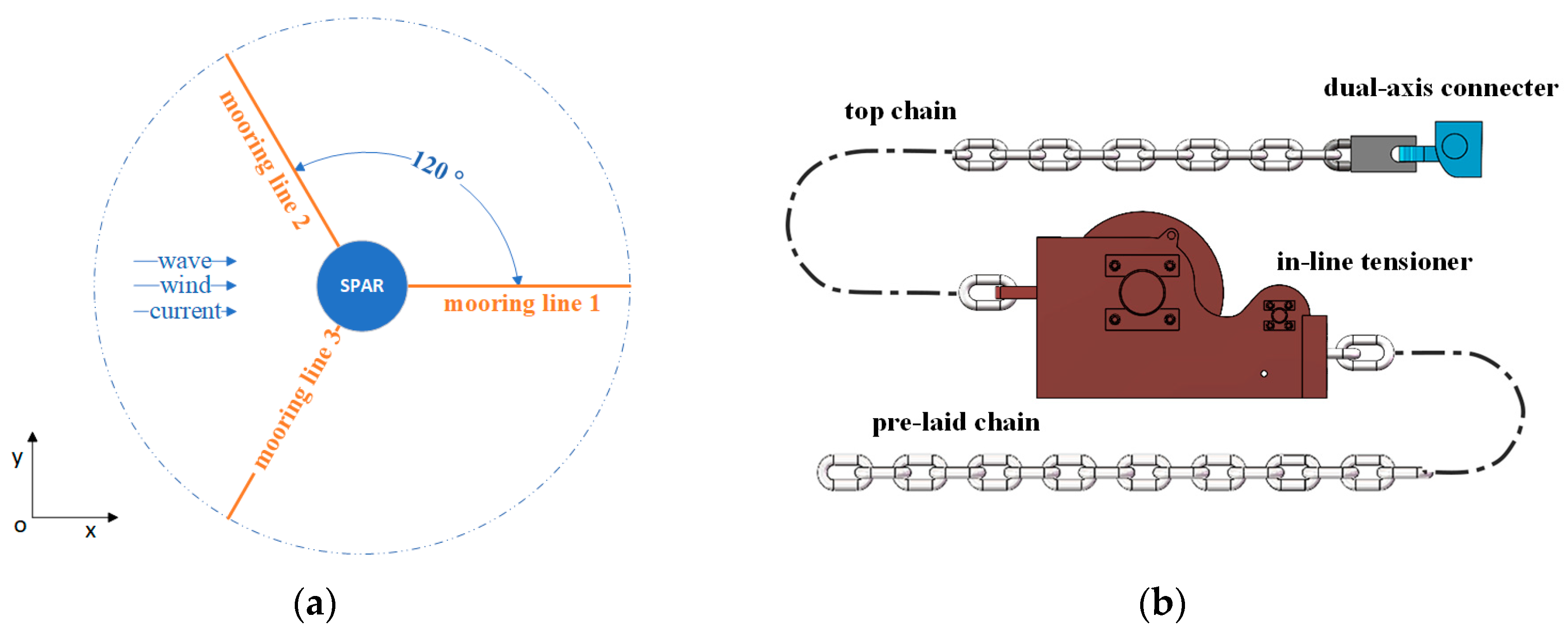
As shown in
Figure 3a, one mooring line aligns with the X axis, whereas the other two are symmetrically positioned on either side of the X axis, thereby securing the spar platform in a central position. From a top–down perspective, each mooring line is precisely spaced 120° apart from the others. In this study, the initial arrangement scheme of the in-line tensioner is similar to that planned for the floating offshore wind farm in Lannion, but only set on one mooring line in the three-line mooring system [
28].
Figure 3b expounds the initial arrangement of the mooring line with the in-line tensioner, consisting of a top chain part, connected to the spar structure by the dual-axis connecter to avoid out-of-plane bending on the first connecting link, and a pre-laid chain connected to the anchor. The in-line tensioner connects the two parts and forms a 902.2 m mooring line of the same length as the OC3 project for subsequent analytical studies.
2.4. Fully Coupled Analytical Calculation Method
The research employed fully coupled load calculations utilizing the dynamic response calculation programs SIMO and RIFLEX [
29,
30]. The modeling and simulation coordination occurred within the established SIMA workbench v.4.3, demonstrating its computational proficiency for OC3-Hywind by delivering dependable outcomes when juxtaposed with a range of numerical tools during the fourth-phase evaluation of the OC3 project [
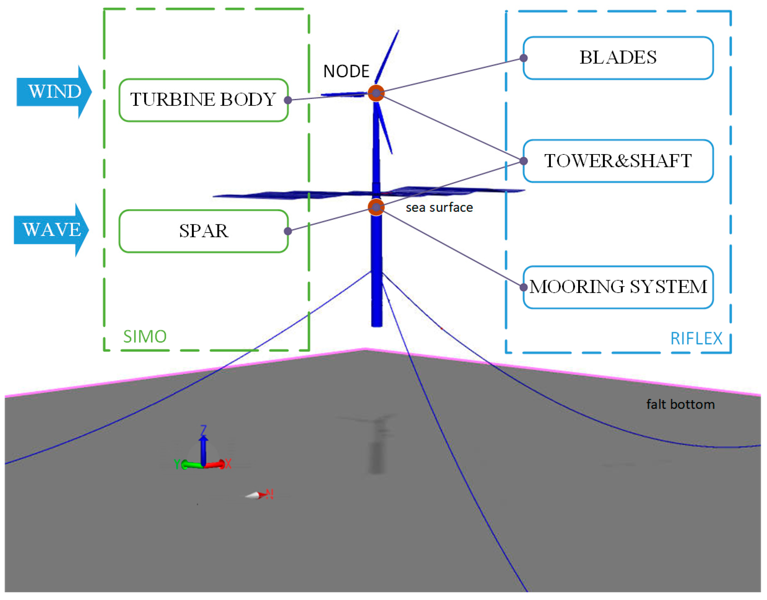
27]. In the fully coupled simulation, it is essential to describe the mechanical dynamic response behavior of the aerodynamics, hydrodynamics, and structural dynamics of the system. The components that need to be described include the turbine, blades, shaft, tower, SPAR structure, and the mooring system. The fully coupled model used for the calculations is illustrated in
Figure 4.
The SPAR structure is described in the SIMO as a rigid body with specific mass properties and hydrostatic stiffness data. The calculation of linear radiation forces is achieved through the convolution of a delay function combined with infinite-frequency additional mass. Low-frequency damping for horizontal motion is represented using a quadratic damping coefficient. The determination of linear wave excitation forces relies on the potential flow coefficient, while the assessment of the averaged wave drift force coefficient relies on the potential flow coefficient. Additionally, a portion of the turbine is also described as a rigid body in the SIMO, possessing wind coefficients and mass properties.
RIFLEX has the advantage of describing slender structures that are small in comparison to diameter and wavelength. In the FOWT system, components such as blades, shafts, towers, and mooring lines fall under this category of slender flexible structures. For the wind turbine structural model, the blades and shaft line are described in terms of refluxate blade lines and are defined using flexible beam elements, with external blade lines and internal eccentricity lines. The shaft line, incorporating flex–joint connections, is represented by axisymmetric beam elements, facilitating the definition of torsional stiffness. The modeling of the tower is conducted using linear elastic beam elements to describe the mechanical behavior of the tower structure under wind loads. The mooring line is discretized into finite elements and simplified into a uniform circular cross-section homogeneous element with equivalent mass. The mechanical properties of the mooring line are described by defining cross-sectional parameters, allowing for an analysis of its behavior under various loads, thereby accurately capturing its response characteristics.
The coupling connection between SIMO and REFLEX is defined by a common node, where the mooring lines are connected to the SPAR structure by a fairlead point, realized by establishing a leader–follower relationship to achieve the common node. The tower is flexibly connected to the top of the spar and shaft line to form a common node. The turbine body, blade lines, and shaft lines are connected by defining common nodes on the hub, forming a coupled analytical model that describes the kinematic and mechanical properties of the FOWT.
The rotor loads for turbine blades are computed using the blade element momentum theory. This method considers dynamic wake and stall effects, blade tip and hub loss corrections, and yawed inflow corrections. The aerodynamic loads are shown as secondary drag loads, with integrated structural damping as stiffness-proportional Rayleigh damping. As shown in Equations (1) and (2), the hydrodynamic loads are calculated according to Morison’s generalized equation, where the total fluid force acting on each element is tangent to the structure, which includes inertial and viscous drag loads and considers the Froude–Krylov force acting in a normal direction to the structure. Inertial effects are considered by accounting for linear mass acceleration and a hydrodynamic additional mass term, which accounts for water scattering pressure due to object acceleration in a fluid medium.
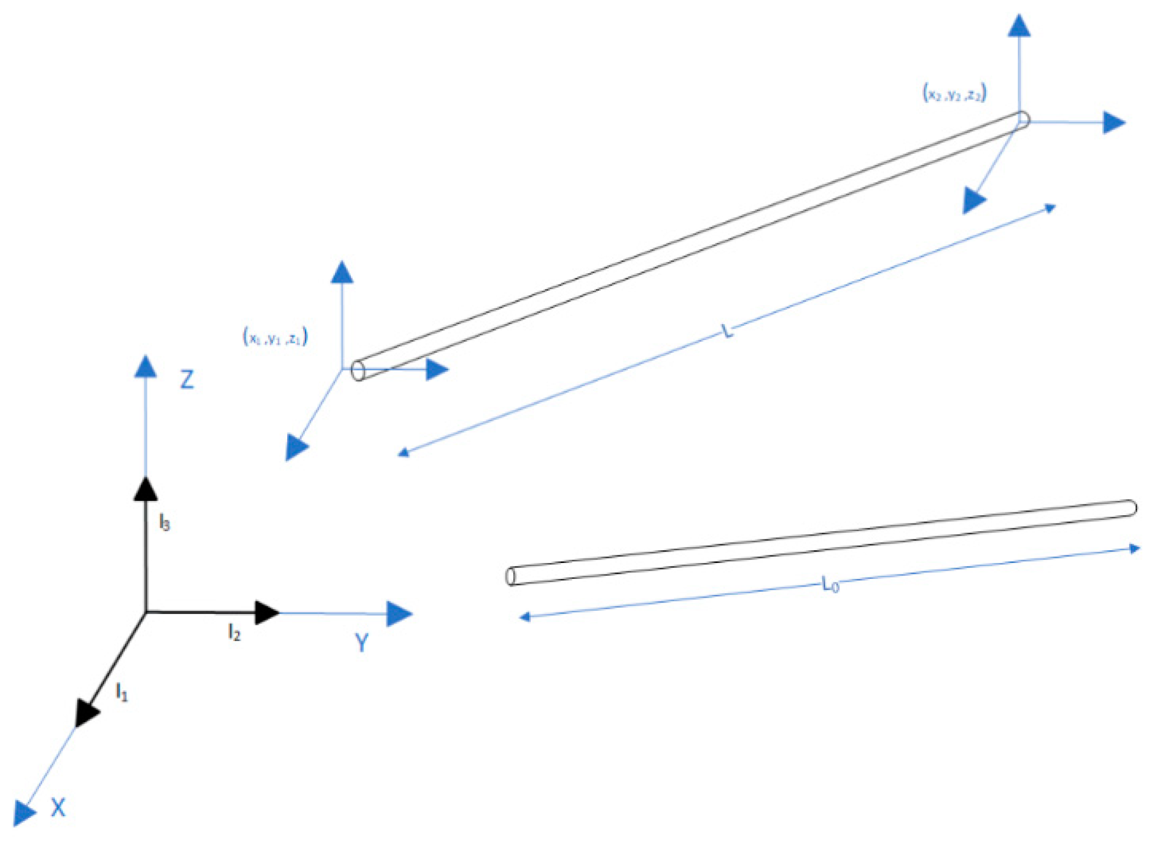
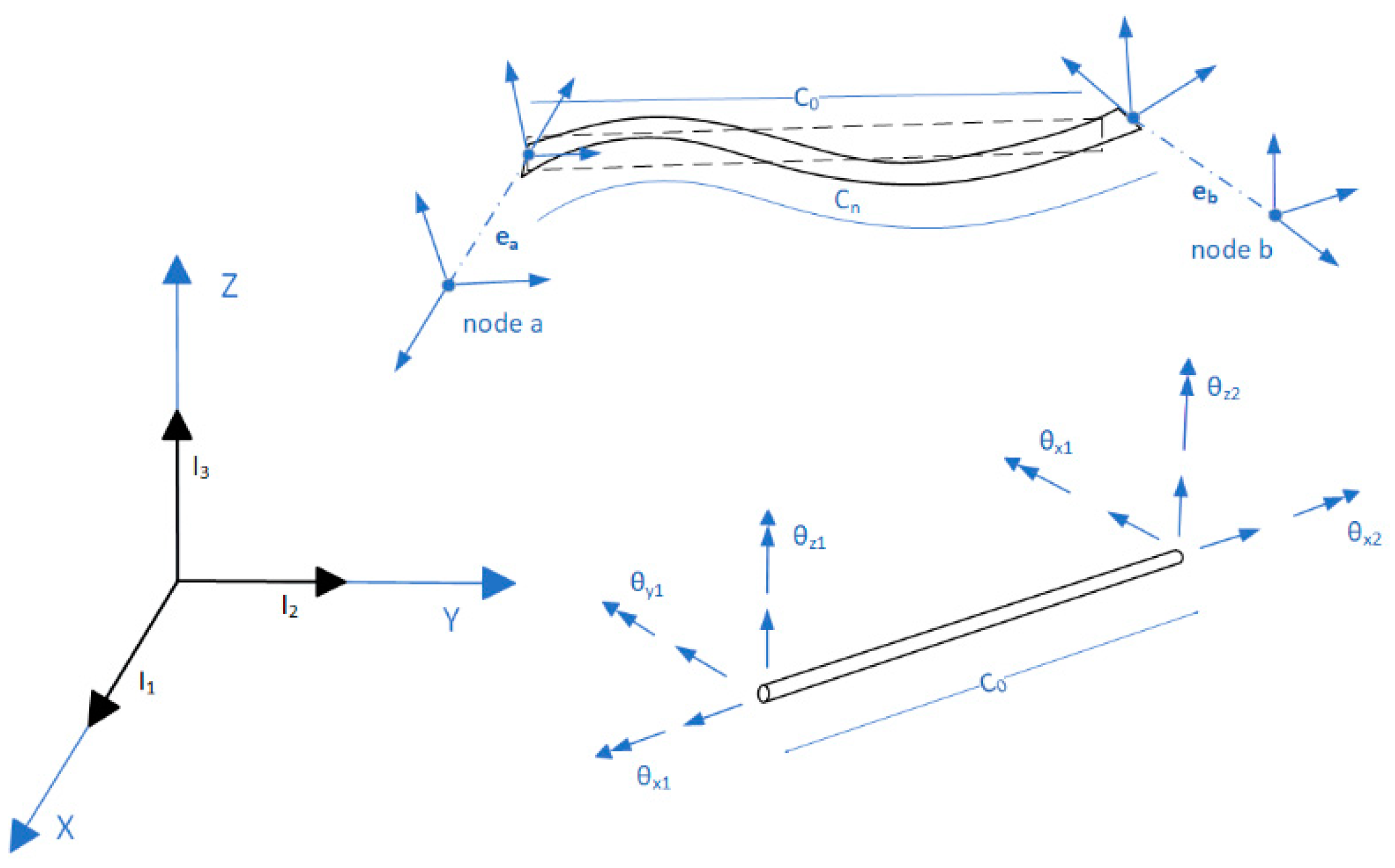
In the coupled computational model, the accurate description of the dynamic behavior of the mooring lines is achieved through the precise definition of the position and orientation of each node in space. To accomplish this, each node of the unit has six degrees of freedom, described using base vectors and orthogonal rotation matrices. This enables the computation of forces and moments on the mooring line model, considering the relative motion and orientation of each node. This approach enables modeling complex interactions between the mooring line and its surroundings, facilitating the precise analysis of its dynamic behavior.
Finite rigid bodies are added at the finite element node to simulate the eccentricities of the finite rigid bodies at the node. As shown in Equation (3), the rigid body surface point P is described as the current state of a rigid element, and its primitive state is defined by the vector
; when deformation occurs, its position is represented by the position vector with the rotation matrix component
Tij of the node added.
4. Results and Discussion
4.1. Discussion on the Results of Arrangements on Different Mooring Lines
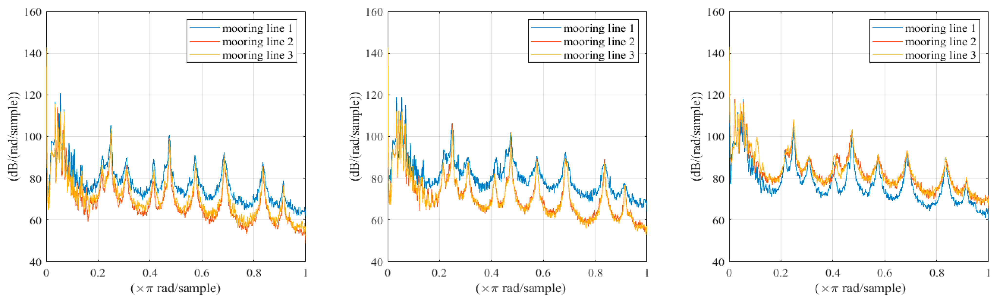
In this study, using the model-building method discussed above, adequate calculations were implemented in the time-domain computer program SIMO-RIFLEX through fully coupled load calculations. We accurately compared the dynamic response of the in-line tensioner when the in-line tensioner was not included and when the tensioner was arranged on three different mooring lines. All mooring lines are divided into three parts: the top chain segment, the in-line tensioner segment, and the pre-laid chain segment. To evaluate the impact when the in-line tensioner is arranged on different mooring lines, a case where the tensioner is arranged 50 m from the fairlead along the mooring line length on different mooring lines is selected for comparison. Based on the time-domain data of the dynamic tension response of the tensioners on the mooring lines, in the case of DCL1, the average tension when arranging the in-line tensioners on mooring lines 1, 2, and 3 is 10% of the minimum break strength of the in-line tensioners. The results shown in
Figure 10 indicate that, based on the time-domain data of the dynamic tension response of tensioners on three different mooring lines, the power spectral density reveals a significant change in lines 2 and 3 compared to line 1, characterized by a noticeable difference between the troughs of waves and troughs in the wave frequency range. This suggests that mooring line 1 is more significantly affected by the wave frequency range. Based on the results, it is evident that the dynamic tension response is similar when the in-line tensioner is arranged on mooring line 2 or mooring line 3. However, the dynamic tension of the in-line tensioner arranged on mooring line 1 has unique response characteristics. This is related to the symmetrical arrangement of mooring line 2 and mooring line 3, while mooring line 1 is located on the lee side so it has different response characteristics.
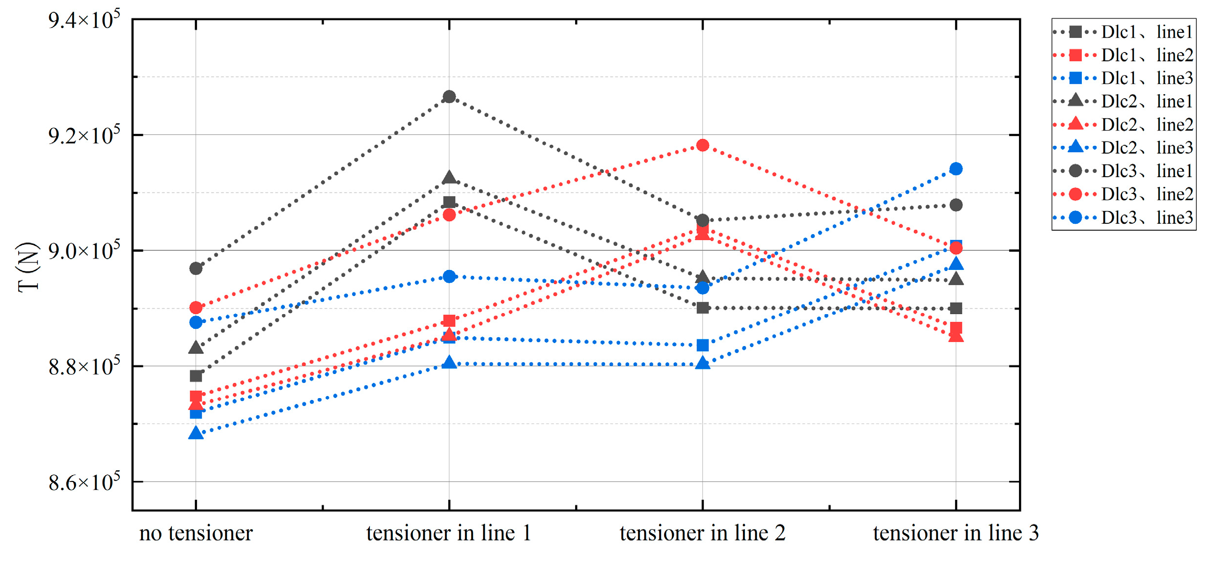
In this case, the mean tension of all mooring lines is compared between different arrangements of the in-line tensioner and the classical catenary mooring without an in-line tensioner. The comparison of this change is shown in
Table 6 and
Figure 11. When the in-line tensioner is used on a mooring line under different sea conditions, the average tension in each of the three mooring lines increases. It is worth noting that the line with average mooring tension increased the most with the in-line tensioner, which also changed the maximum average mooring tension line from the previous mooring line on the lee side to the mooring line with the in-line tensioner. Attention should be paid to the transformation of the maximum average tension line to avoid the underestimation of average mooring tension. The amplitude of this increase did not increase with the severity of the sea state and wind speed, but was kept at a relatively close value.
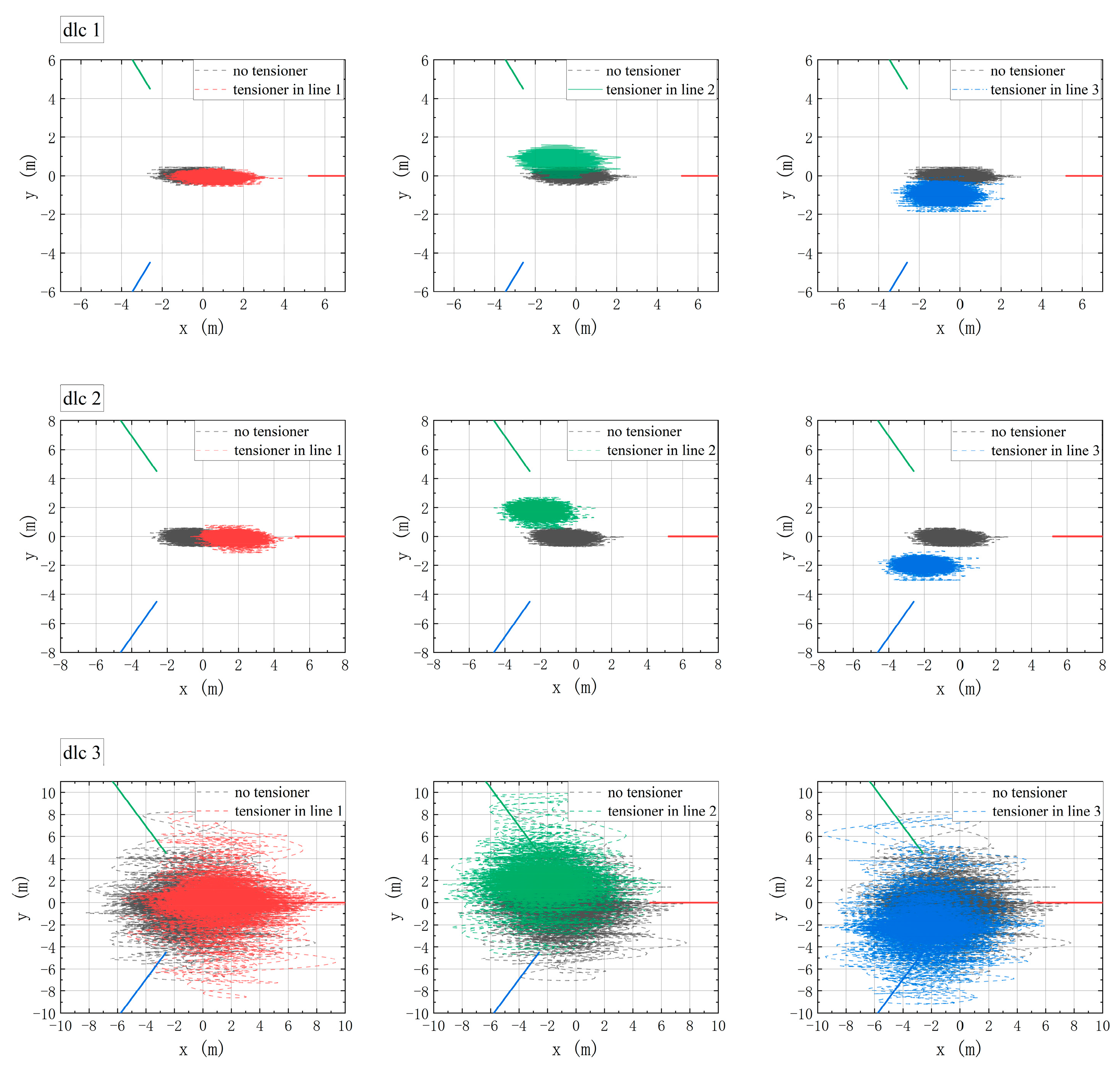
This study also compares the displacement changes of floating offshore wind platforms over time and finds that the in-line tensioner arrangement on different mooring lines will affect the platform movement. It can be seen from
Figure 12 that in different sea states, the movement trajectory of the platform on the XOY plane is offset to the side of the in-line tensioner, but it has no obvious influence on the overall movement trajectory. Among them, when the in-line tensioner is arranged on mooring line 1, the motion of the platform does not change in the y direction, but only shifts in the x direction, while when the tensioner is arranged on mooring lines 2 and 3, the platform movement trajectory shifts to the position where the in-line tensioner is arranged, and the deviation degree is higher when the tensioner is arranged on mooring line 1. However, this degree of position deviation is within an acceptable range and will not pose a threat to the operation of the wind turbine.
The influence of the position of the in-line tensioner on the change in heave motion can be seen in
Figure 13. When the in-line tensioner is used in the mooring system, no matter which mooring line is arranged, the mean value of displacement change in the heave direction decreases, but the variation amplitude of heave motion does not change. Moreover, the change in the platform motion amplitude is mainly affected by the sea state, and the in-line tensioner only causes deviation, and does not increase the amplitude change. This degree of position deviation is acceptable for wind platforms, which are less sensitive to mooring motion changes than oil platforms. This is also related to the stability of the spar structure. Spar structures always have good stability in deep water.
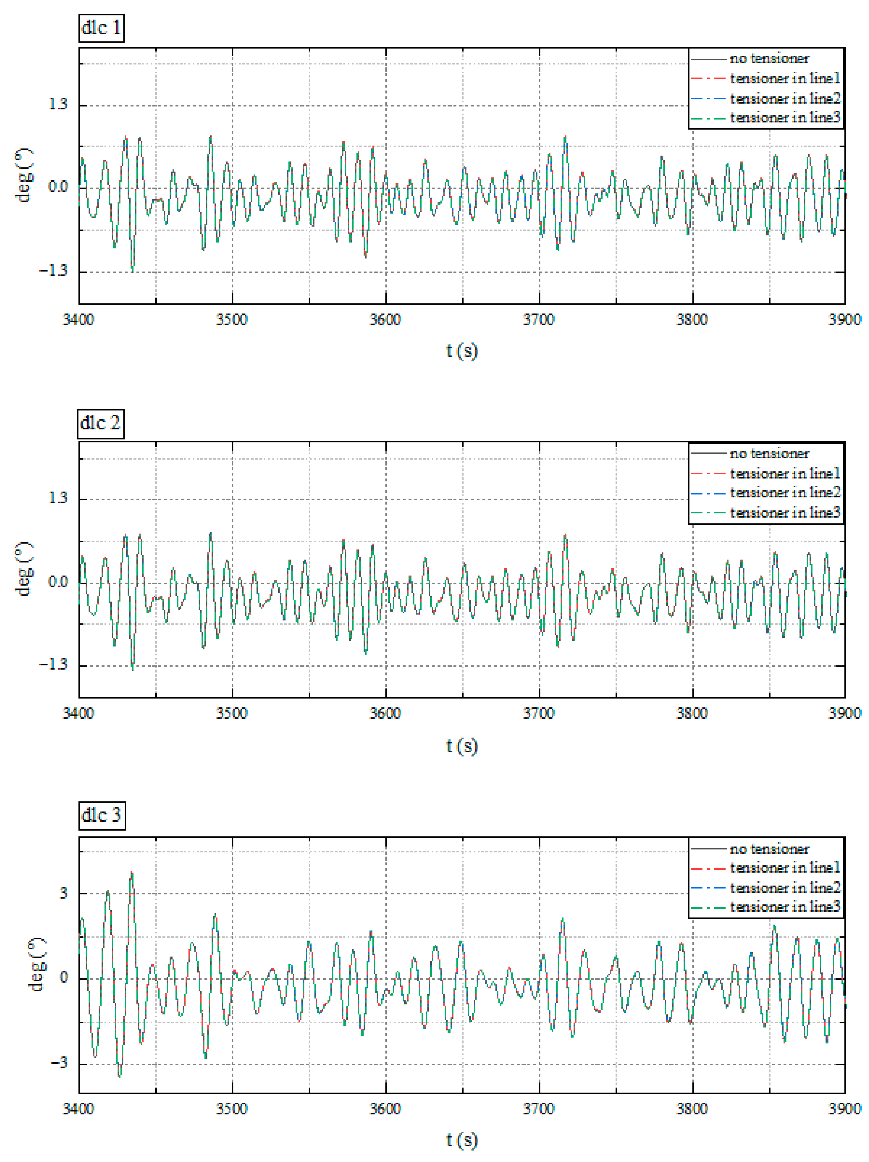
It can be seen in
Figure 14 that when the in-line tensioner is arranged on different mooring lines, the
X-axis rotation motion of the floating offshore wind platform is influenced. Because mooring line 1 is in the incident wind direction, in the same direction as the
X-axis, and has good symmetry, it has the least influence on the rotation of the
X-axis. In addition, the influence of the arrangement of the tensioner on the rotational motion of the
X-axis does not change the period and frequency of the change and has no obvious effect on the amplitude. Generally, the influence of the change of
X-axis rotation motion caused by the use of a tensioner is limited.
It can be seen in
Figure 15 that when the in-line tensioner is arranged under different mooring lines, it has no effect on the rotational motion of the
Y-axis of the floating offshore wind platform, and the calculated results demonstrate strong consistency across varying sea conditions.
4.2. Discussion on the Results of Different In-Line Position Configurations
To study how various configurations of in-line tensioners on a single mooring cable affect the change in mooring tension, the upwind line with the maximum load is taken as the research object. The in-line tensioner was installed on line 1 at different distances from the fairlead. These distances included 50 m, 100 m, 200 m, 300 m, 400 m, 500 m, and 550 m for the purpose of conducting a comparative study.
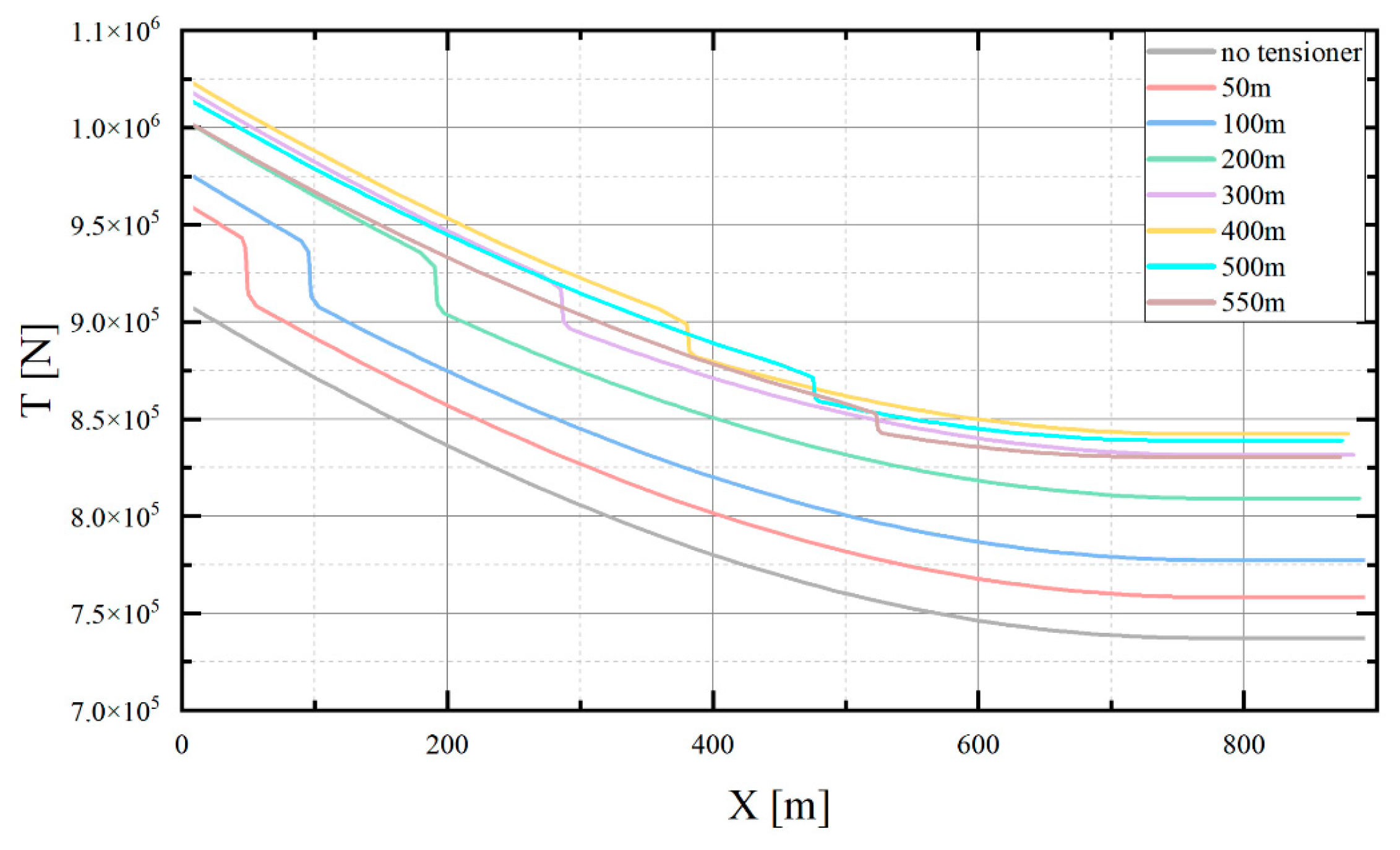
Figure 16 shows the mooring tension results of the static analysis under different arrangement conditions of the tensioner on mooring line 1. There is a significant sudden change in static analysis results at the in-line tensioner, producing a tension change of about 28 kN at 50 m, and this tension change decreases as the in-line tensioner moves away from the fairlead, producing a tension change of about 17 kN at 550 m. This change in tension results in the presence of a high-tension section in the tension distribution of the mooring line, which is in the top chain section between the in-line tensioner and the fairlead, and increases in distance as the tensioner moves away from the fairlead. The maximum and minimum values of the mooring static tension of the mooring line show a parabola trend correlated with the change in the position of the in-line tensioner on the mooring line. This may be because the chain segment of the in-line tensioner has changed the mooring damping, which results in a large amount of energy dissipation in the middle of the mooring line, and the motion characteristics of the mooring line with the in-line tensioner are changed. When the position of the tensioner changes between 0 m and 100 m, the tension changes faster and reaches an extreme value at about 400 m, which increases by about 112 kN compared with the mooring line without the tensioner.
Based on the findings presented in
Figure 17, it appears that the in-line tensioner does not have a significant impact on the geometry of the mooring line at various positions. However, there is a noticeable partial change in the shape of the mooring line due to the concentration of mass at the tensioner location.
Figure 18 shows the results of the average value of the time-domain data of the dynamic tension response when the in-line tensioner is arranged at different positions on the mooring line. The average tension value from 2000 s to 8000 s after a wave is fully developed in the time-domain results. It can be seen from the results that as the arrangement of the tensioner is farther away from the fairlead, the mean tension value at the in-line tensioner decreases. From 50 m to 550 m, the tension at the fairlead decreases by about 130 kN, and this degree of change is not affected by different wave and wind conditions. This is consistent with the tension variation law of the mooring line without a tensioner as it is farther away from the fairlead. However, it is worth noting that different arrangement positions of the tensioner within the line cause changes in the average value of the dynamic tension at the fairlead. As shown in
Figure 19, as the distance between the in-line tensioner and the fairlead changes; under the conditions of dlc1 and dlc2, the maximum value at 300 m is 17 kN smaller than that at 50 m. Under the conditions of dlc3, the gap is 12 kN. This is a point worthy of attention when arranging the tensioner. The tensioner should not be arranged in the middle of the chain segment but should be close to the position of the fairlead or the touchdown point of the catenary.
It can be seen from
Figure 20 that, under different arrangements of the in-line tensioner on the mooring line, the changes in the displacement and rotational movements of the platform in various directions can be observed. Among them, the platform movement position in the
X-axis direction is the most obviously affected. This is because the in-line tensioner will cause the platform’s movement to shift to the side where the in-line tensioner is located. When the in-line tensioner is on the middle part of the mooring line, it has a more significant impact on the movement of the platform. As can be seen from
Figure 21, the change in the position of the in-line tensioner on the line has minimal impact on the rotational movement of the platform.
4.3. Discussion on Reverse Tension at the In-Line Tensioner
In the DNV specification [
34], it is stated that if a mooring connection device must be used, its operation performance must meet the requirements of the long-term stable operation of the mooring system. Reverse tension happens in the process of changing equipment in a short period from a tension state into a compression state. Reverse load will cause extreme tension and sudden change, threatening the safety of the mooring system.
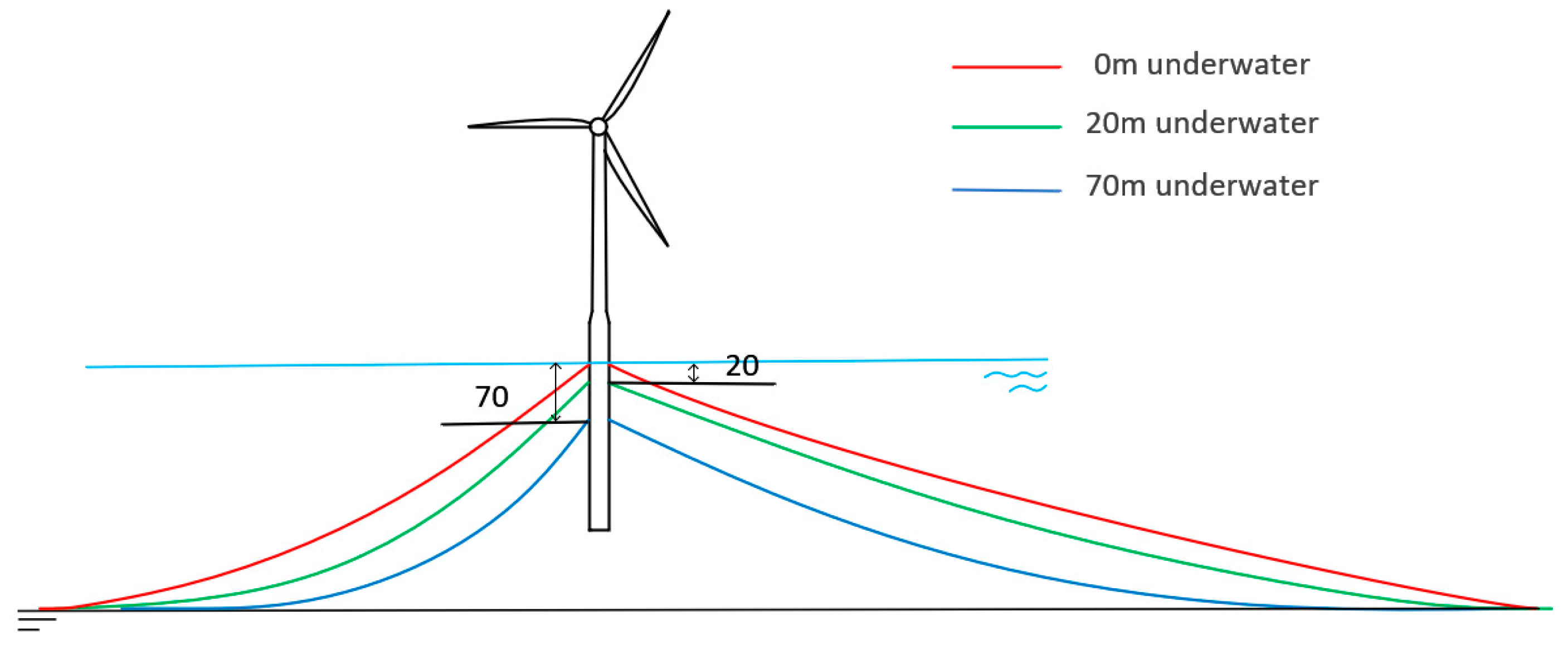
As a piece of special connection operation equipment, the special tension response of the in-line tensioner should be fully studied. The main design intention of the in-line tensioner is a one-way braking device, although there will be additional locking measures after tensioning is in place; it will be completely locked in both directions, but in terms of the design intention, reverse tension presents an abnormal working state. In general, reverse tension occurs more frequently at the fairlead; reverse tension in the fairlead has been confirmed to exist, and most previous studies have focused on this. However, during the research process, we also found that changes in the configuration of the mooring line with the in-line tensioner will affect the occurrence of reverse tension. The movement of the platform is influenced by changes in fairlead position, which in turn affect the tension response of the mooring line. To study the most intense condition of dlc3, three situations were set, respectively, in which the fairlead was located under the water at 0 m, −20 m, and −70 m, and the in-line tensioner was arranged on mooring line 1 in the direction of wave and wind incidence. A setup diagram of the analysis model is shown in
Figure 22.
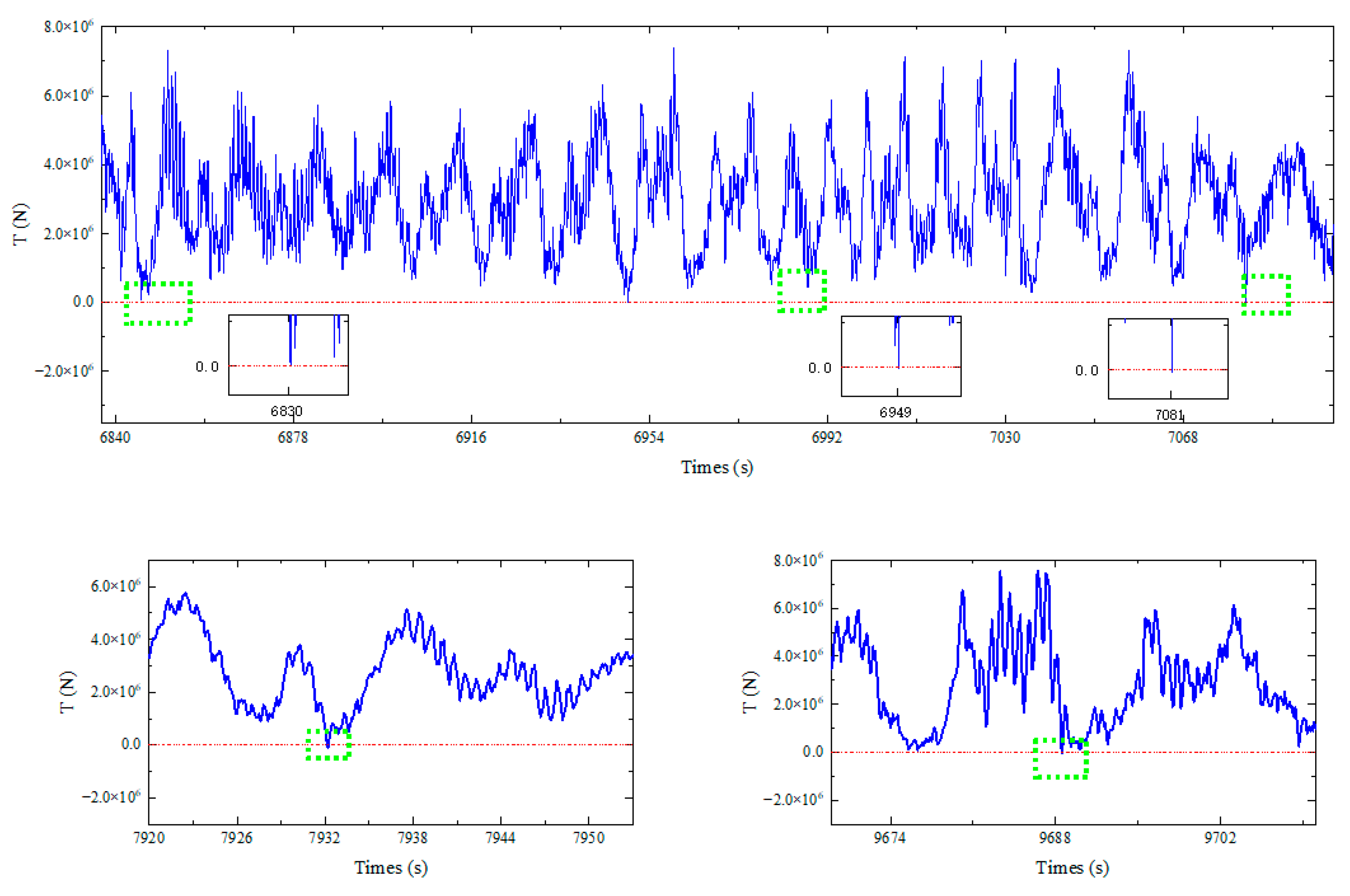
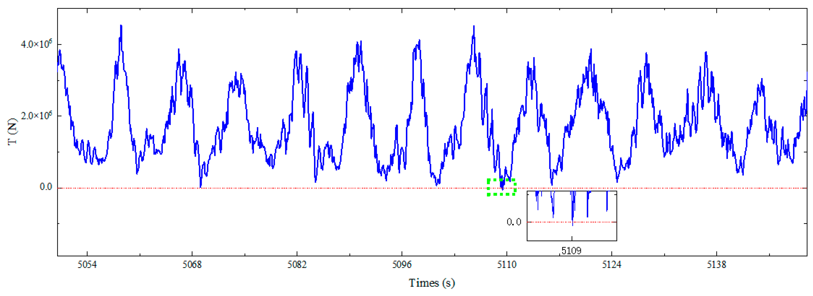
As the fairlead approaches the water surface, the fluctuation amplitude of the mooring tension and the average mooring tension increase significantly. When the fairlead is located 20 m and 0 m underwater, the phenomenon of reverse tension appears in the process of tension response. As shown in
Figure 23, when the fairlead is located 0 m underwater, five times the amount of reverse tension appears at the in-line tensioner, respectively, at 6830 s, 6949 s, 7081 s, 7932 s, and 9688 s, and the reverse tension is 17.312 kN, 17.256 kN, 34.858 kN, 86.371 kN, and 53.090 kN. As shown in
Figure 24, when the fairlead is located 20 m underwater, there is reverse tension at the in-line tensioner, which occurs at 5109 s at a value of 60.379 kN. However, when the fairlead is 70 m underwater, there is no reverse tension at the in-line tensioner.
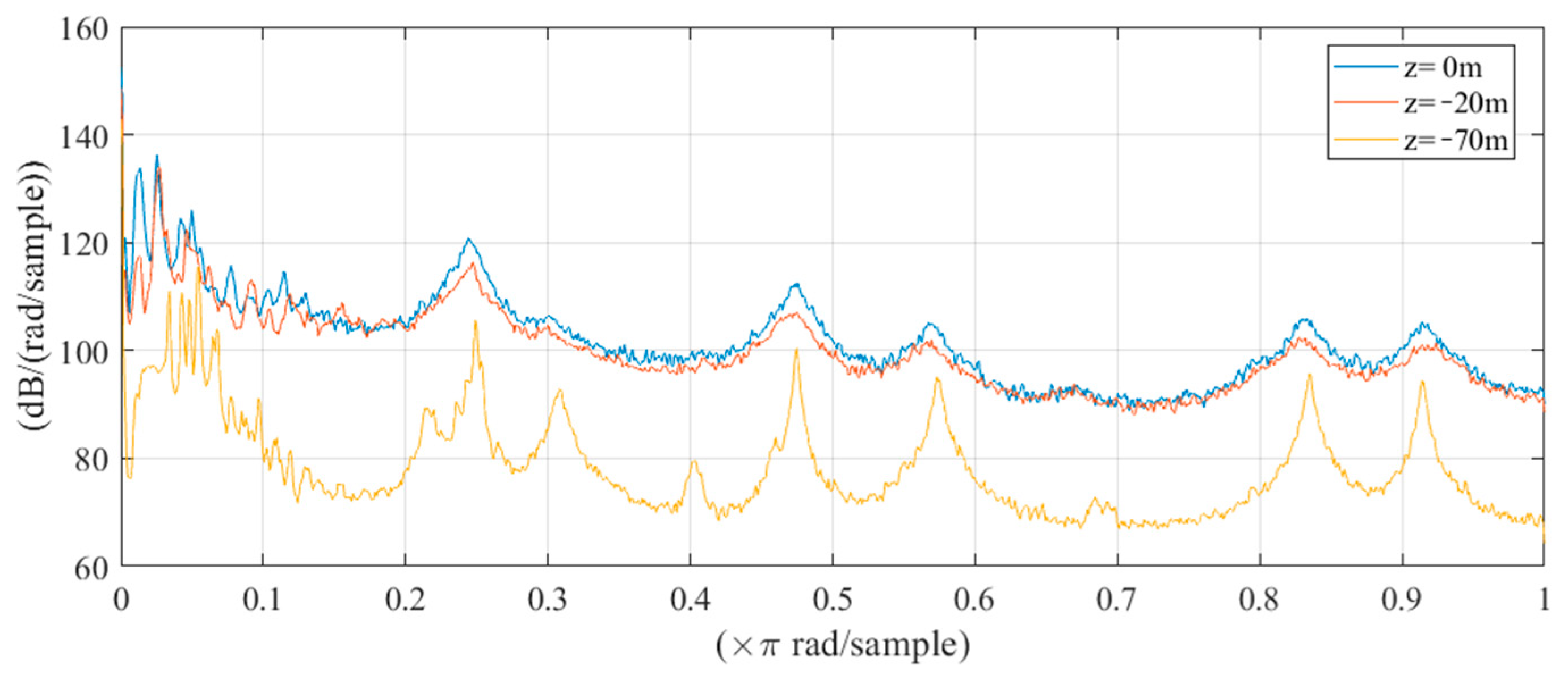
Figure 25 shows that when the mooring line is positioned close to the sea surface, configurations with reverse tension exhibit similar responses in the frequency domain, all of which are greater than those cases without reverse tension. The changes in the layout of the mooring line significantly intensify the dynamic responses of the mooring lines across various frequency bands, leading to reverse tension at the tensioner. This situation is detrimental to the operation of the equipment and poses a threat to the safety of the mooring system. As a new type of compression-sensitive component, the in-line tensioner should be designed to avoid reverse tension.
4.4. Suggestions for Mooring Systems with In-Line Tensioners
From the above analysis, it can be found that when the in-line tensioner is adopted in the mooring system, the maximum average mooring tension position changes from the original lee side to the mooring line with the in-line tensioner. This change necessitates close attention to changes in hazardous positions during the design and inspection process. Placing the tensioner on different lines causes deviation in the platform’s displacement trajectory and reduces its heave motion. This deviation can be ignored in single arrangements; however, its impact on grouped arrangements must be considered. To avoid a high-tension section on the mooring line, the location of the tensioner should be arranged close to the fairlead or touchdown point, instead of in the middle section of the mooring line. It is a significant concern that after using the in-line tensioner, the top chain will have a higher tension load. Therefore, a higher specification of the top chain can be considered to meet the safety requirements.
It is important to consider using an in-line tensioner throughout the preliminary scheme phase of FOWT mooring systems. The position of the fairlead and anchor point should also be comprehensively evaluated to minimize the amplitude of tension change and prevent the mooring line from experiencing reverse tension or relaxation to near-zero tension values. Since the existence of reverse tension is confirmed, higher requirements should be put forward not only for the mooring configuration, but also for the in-line tensioner design. A reverse locking device should be required in the design specification to achieve two-way locking, and the structure should be able to withstand a certain range of reverse tension. Considering the presence of higher tension amplitude phenomena, there should also be more detailed specifications for fatigue problems.
According to the research results, in-line tensioning is a new technology worthy of promotion in the FOWT industry. Under conditions considering wave effects, the use of an in-line tensioner for FOWTs will result in changes in response; however, this will not compromise the operational safety of the platform. Given its significant economic advantages, this approach also offers considerable technical benefits. It can be concluded that the utilization of an in-line tensioner can effectively fulfill the requirements of safety and reliability. However, it is crucial to carefully monitor the alterations in dynamic response resulting from changes in layout position.


