1. Introduction
The emission of greenhouse gases and air pollutants resulting from the overuse of fossil fuels is considered to be one of the primary causes of climate change. Harnessing renewable energy to gradually replace existing fossil fuels is one of the most effective approaches to addressing these issues and has already taken action worldwide. Wave energy is characterized by its wide distribution, abundant reserves, relatively low environmental impact, and ample installation locations for wave energy facilities. It is considered to be one of the most promising clean energy technologies among various marine energies. According to several surveys, the power potential of waves on all coasts throughout the world is estimated to be about 0.8 × 10
13–8 × 10
13 kWh/y [
1]. It is foreseeable that the development of ocean energy, particularly wave energy, will usher in a new era of growth.
In China, the total energy consumption in 2023 amounted to 4.74 × 10
13 kWh, marking a year-on-year increase of 6.5%, and accounting for 27.6% of the total global energy consumption [
2]. As the world’s largest energy producer and consumer, China bears an unshakable responsibility for energy saving and emission reduction. In 2021, the Action Plan for Peaking Carbon Emissions by 2030 [
3] was issued by the State Council of China, which explicitly considers the development and utilization of ocean renewable energy, including wave energy, as one of the key measures in adjusting the industrial structure and energy composition to achieve the planned goal for peak carbon emissions. According to the survey data of professional institutions [
4], the effective power of wave energy that can be developed in China’s coastal, near shore, and adjacent sea areas is estimated to be around 5.76 × 10
8 kW. Theoretically, the annual total quantity that can be mined is equivalent to 6.21 billion tons of standard coal, accounting for 10.65% of China’s total energy consumption in 2023 and 64.9% of the total consumption of electricity and other energy sources represented by nuclear power, wind power, photovoltaic, hydropower, etc.
1.1. Background
The amount of renewable energy in waves is so great that many scholars have proposed various energy conversion devices to harness this energy. The development of wave energy is generally achieved through wave energy converters (WECs) [
5], which are usually used to drive induction generators. There have also been some studies dedicated to providing green power for seawater desalination [
6] or power propulsion for mini-type marine equipment [
7] using wave energy devices. Among the various wave energy systems currently under research and implementation, the hinged multi-raft system is an important type. Compared to other types of WECs, the hinged multi-raft system remains underdeveloped, and there is still a need to further enhance its wave energy conversion efficiency.
The WEC concept developed to date includes two main types of point absorbers and line absorbers, depending on the structures of the floating body and wave energy capture characteristics. The multi-raft system is generally considered a line absorber, which occupies a certain length of the wave surface along the wave direction and generally drives the power take-off (PTO) system through the relative pitch motion between adjacent rafts [
8]. The theoretical wave energy capture width of the line absorber is calculated to range from 0.50
λ to 0.73
λ (λ: wave length) [
9]. The multi-raft system is moored in an offshore or near-shore wave farm by single-point mooring or multi-point mooring systems. Therefore, unlike the coastal WEC, the layout of the multi-raft WECs is less restricted by wave conditions, water depth, and tidal changes, which gives them unparalleled advantages in large-scale development.
This multi-raft system consists of several rafts floating in waves, which are hinged by connecting pairs containing hydraulic PTO units. The floating rafts undergo pitch motion under the excitation of waves. The relative pitch motion around the joint is generated between adjacent rafts, which drive a pair of hydraulic cylinders to operate. The hydraulic oil in the pipeline of the PTO system is pumped into the hydraulic motor by the hydraulic cylinder, and the induction generator connected coaxially is driven by the hydraulic motor to produce electricity. In recent years, some innovative power generation design concepts have also been explored for application to the PTO system of WECs, such as linear motors, piezoelectric generators, etc. [
10,
11]. Among these multi-raft systems, the most representative is the Pelamis raft wave power generation system [
12] developed in the UK. It is worth mentioning that Pelamis has received widespread attention from the global industry as one of the successful market-oriented applications of multi-raft WECs. Mocean Energy, based in Edinburgh, has developed several multi-raft WECs, named Blue Star, Blue Horizon, and Blue X, which have been used in projects ranging from small off-grid to large-scale utilities [
13,
14].
1.2. Literature Review
1.2.1. Multi-Raft WECs
The multi-raft WEC was first proposed and researched in the 1970 s. Haren P. and Mei C.C. [
15] analyzed the hydrodynamic characteristics and wave energy conversion efficiency of the Hagen–Cockerell raft, in which a linear PTO viscous damping was employed. In their study, an optimization method for the number of floating rafts in series was proposed. Dalton G. J. et al. [
16] investigated the Pelamis WEC over 20 year project duration, collecting wave energy data from various global locations to determine its performance and economic viability. Rusu E. et al. [
17] selected the north of Peniche, Portugal, where wave energy potential is immense, as the target region, and evaluated the consequences of the Pelamis WEC on the local and coastal environment.
Chen W. C. et al. [
18] assumed the pitch motion of rafts to be completely symmetrical in their research on the wave energy conversion efficiency of a raft-type WEC composed of two-section rafts with elliptical cross-sections. Additionally, the investigated WECs were optimized for typical wave conditions in the seas around China. In their subsequent research [
19], they analyzed the dynamic response of the wave energy conversion of asymmetric articulated multi-raft systems using numerical simulations and experiments. Dong J. G. et al. [
20] conducted research on the wave energy capture performance of a wave energy device with elliptical and cylindrical rafts, and obtained the optimal structural parameters in a three-level sea state. Jin S. Y. et al. [
21] studied two-body hinged raft WECs with the aim of obtaining further insight and data through numerical research using WEC-Sim.
In the design and testing of multi-raft WECs, Mocean Energy [
14] adopted two rafts with novel geometries and different natural frequencies to achieve the maximum relative pitch amplitude between adjacent rafts. Moreover, artificial intelligence optimization methods were first employed in the design process. Gao H.T. et al. [
22] employed numerical simulation to analyze the operational characteristics of three-raft WECs with rectangular, elliptical, ship-shaped, and capsule-shaped rafts, respectively. It was found that the capsule-shaped raft was most conducive to wave energy capture by the device. He K.D. et al. [
23] employed numerical simulation methods to investigate the impact of built-in tanks on the motion and response power of a two-raft WEC. They discovered that the sloshing tank reduced the heave amplitude of rafts and increased their pitch angle.
Li B. (the author of this paper) and Gao H.T. et al. [
24] conducted a profound study on the hydrodynamic performance of hinged multi-floating raft wave energy devices. The PTO connection between the floating bodies is treated as first-order viscous damping and elastic damping. In subsequent continuous research, the separation of variables method for frequency-domain analysis and multi-scale theory for time-domain approximate analysis of the rafts governing equations were employed. A series of simulation calculations were completed in a three-dimensional numerical wave tank (NWT), considering the effect of wind and current. In 2013, several sea trials of this type of device were carried out, and the hydraulic PTO system used in the experimental device successfully achieved electrical energy output (as shown in
Figure 1).
1.2.2. PTO System
The PTO system is a key mechanism for energy extraction in WECs. The hydraulic PTO (HPTO) system has dominated the application of PTO systems for multi-raft WECs due to its advantages such as high reliability, high conversion efficiency, long lifespan, and ease of implementing optimized control. The research conducted on the HPTO system is also the most in-depth and extensive. In recent years, many scholars have also proposed many innovative designs and tests based on traditional HPTO systems.
Yang Q. J. et al. [
25] studied the motion and energy absorption ability of a three-raft WEC using CFD techniques by assuming that the hydraulic PTO system acts as a quadratic damping unit and showed that an optimal quadratic damping exists for maximizing power absorption. Zheng S. M., Zhang Y. L. et al. [
26] studied the motion performance of a two-section articulated floating wave energy device with linear damping of the PTO system, and explored the maximum wave energy conversion efficiency and the PTO damping effects via numerical simulation. Mérigaud A. et al. [
27] developed a precise and efficient spectral control scheme for non-ideal PTO systems characterized by an efficiency factor smaller than unity. This scheme can adjust the obtained power to lie within 80–95% of that obtained by simply applying the efficiency factor to the optimal power with ideal PTO systems. Shi Q.J. et al. [
28] proposed a torsion bi-stable mechanism to enhance the absorption efficiency of the linear PTO system used in the raft-type WEC. Their research found that the bi-stable mechanism significantly improved the capture efficiency of WEC and extended the range of the high efficiency to lower frequencies.
Liu C. H. et al. conducted multiple optimization efforts on the simulation model of the hydraulic PTO system applied to raft-type WECs. In reference [
29], a new hydraulic PTO system based on the individual metering technology for application in the raft-type WEC was proposed, which has been validated to significantly enhance the power capture performance of the WEC. In reference [
30], an accurate model for the hydraulic PTO system for a two-raft WEC was presented. This model includes pressure loss, flow rate loss, friction, and flow resistance. In order to simplify the process of determining the appropriate locking time, the hydraulic PTO system was further represented as a Coulomb model [
31]. In reference [
32], a novel discrete control strategy for a hydraulic PTO system was proposed to improve the power capture performance of WECs, where separate switching valves were installed on the hydraulic PTO system to make it more controllable.
Zhang H.C. et al. [
33,
34] designed a simple and effective nonlinear stiffness mechanism by installing an elastic element between the hinged floating rafts; thereby, the capture efficiency of the raft-type WEC was effectively enhanced and its bandwidth was broadened. Jusoh M.A. et al. [
35] utilized MATLAB/Simulink to establish a complete model for an improved hydraulic PTO system applied to WECs, which includes a dual high-pressure accumulator (HPA) module and fluid energy control (FEC) module. Furthermore, they optimized the parameters of the FEC control strategy using a genetic algorithm. Huang Q.T. et al. [
36] established a relatively complete hydraulic PTO model based on AQWA for Pelamis-like WECs, in which the flow and pressure of each branch of the hydraulic PTO, the output torque of the hydraulic cylinder to the buoy, and the electromagnetic torque of the generator were considered. In their research on the effects of multiple degrees of freedom on a raft-type wave WEC, Zhao C.Y. et al. [
37] discussed the impact of the PTO system, which integrates Coulomb damping, on energy absorption. Wang D. M. et al. [
38] discussed a new method for estimating the power output of a two-body hinged raft wave energy converter in the wave basin through the use of a K-means clustering algorithm. Zhang D.H. et al. [
39] designed a single compound hinge-type swing cylinder 6-bar mechanism as a hydraulic PTO system for a multi-body articulated WEC to address the end-stop problem.
1.2.3. Experimental Testing
The purpose of WEC experiments is to verify technical feasibility, optimize system design, validate the correctness of established theoretical or numerical simulation models, and promote commercial applications. The main experimental methods include WEC wave tank experiments, WEC actual sea condition tests, and PTO system bench tests.
Sirigu S.A. et al. [
40] conducted an experimental study on the influence of the mooring layout applied to the 1: 20 scale prototype of the inertial sea WEC on loads in extreme wave conditions. Liao Z.J. et al. [
41] presented the results of tank testing experiments applying a linear non-causal optimal control (LNOC) strategy to the Mocean M100 WEC. The experimental results showed that an LNOC can increase the absorbed mechanical power by up to 126% compared to passive dampers in most test sea states. Kharkesh B.A. et al. [
42] experimentally evaluated the hydrodynamic response of an OWC with nonlinear PTO and optimized the nonlinear PTO using a genetic algorithm. Chen W. et al. [
43] proposed a double-wing wave energy converter suitable for supplying power to ocean platforms, and manufactured a 1: 10 scaled prototype for a tank experiment to study its performance. Zhao C.Y. et al. [
37] conducted scale model tests on the effects of multiple degrees of freedom on a raft-type WEC with the PTO system integrated with Coulomb damping. The results indicated that despite varying damping amplitudes, peak energy absorption is consistent across different wave periods. Han Z. et al. [
44] proposed a novel method for calculating the energy capture spectrum of WECs with complex PTO systems by defining the periodic energy capture matrix as an inherent parameter of the WECs. A numerical model was then established using the WEC-Sim software and was validated by an experimental test.
1.2.4. Hydrodynamic Models
In the hydrodynamic modeling for WEC, the linear potential flow (LPF) model and the Reynolds-averaged Navier–Stokes (RANS) model are the two most widely used hydrodynamic models. Among them, the RANS model can provide a high precision physical representation for wave-body interaction studies, making it dominate the modeling in major CFD software. However, it also has disadvantages, such as excessive computational burden.
In the numerical study of a raft-type WEC with an oval cross-section by Chen W. C. et al., [
18] the potential flow theory of first-order Stokes wave, Newton’s equation of motion, and coupling conditions on fluid–structure interfaces were used for modeling, and the velocity and pressure fields were calculated in the data processing. Cummins C.P. et al. [
45] proposed a new model for viscous dissipation and applied it to the study of an oscillating water column WEC. This model incorporates viscosity into the potential flow model by modifying the inviscid theory in regions of the fluid domain where the influence of viscous dissipation is non-negligible. Feng X. et al. [
46] further demonstrated the potential flow model with viscous dissipation based on a modified boundary element method through simulations of three cases. Liu C.H. et al. [
47] presented a state-space approximation of the convolution term in a time-domain analysis of a raft-type WEC consisting of two rafts and a PTO system aimed at better addressing the issues of PTO nonlinearity and WEC performance control. Zhang Y.X. et al. [
48] established a hydrodynamic model for the snake-like WEC and an equivalent magnetic circuit model of the magnetoelectric transducer to investigate the operating performance of the WEC.Based on a CFD-Unsteady RANS (URANS) analysis, Fontana M. et al. [
49] investigated the identification of viscous damping parameters for WECs to account for their non-linearities. Anderlini E. et al. [
50] applied deep reinforcement learning to the control of a WEC, enabling the device to maximize energy absorption in mild sea states while limiting its motions in high waves. Davidson J. and Costello R. [
51] delved into solutions to address the need for reliable, robust, and affordable simulations of WEC technology in their research review. They emphasized that it is necessary to focus on CFD theories that exist between LPF and RANS, as well as other modeling options that are computationally fast while retaining higher fidelity than LPF. Ni W.C. et al. [
52] established a numerical model of Pelamis WEC in the software ANSYS-AQWA to study its hydrodynamic characteristics and power generation capacity. In their numerical simulations, the torque and power generated by the generation system were calculated by calling external force and power routines at each time step. Abbasi A. et al. [
53] used the boundary element method and computational fluid dynamics methods in their study on the hydrodynamic/dynamic assessment and power capture capability of a two-raft WEC.
1.2.5. Hydrodynamic Interference Between Adjacent Rafts
The hydrodynamic interference between adjacent rafts of a multi-raft WEC has a significant influence on the motion response and wave energy conversion characteristics of the device.
Feng X. et al. [
54] used a fully nonlinear numerical model to study the fluid resonance characteristics inside the narrow gap between two adjacent floating bodies and found that the resonance frequency of the fluid in the narrow gap increases with the incident wave steepness. Li X. et al. [
55] utilized a numerical wave tank established based on the FLOW-3D software to simulate the fluid resonance phenomenon inside the narrow gap between two floating bodies. They discovered that the increase of the wave amplitude in a narrow gap was excited by the fluid motion at the bottom of the floating bodies. Moradi N. et al. [
56] investigated the influence of water depth on fluid resonance within the narrow gaps of two side-by-side bodies using the volume of fluid (VOF) method and two-dimensional numerical wave tank technology based on the Navier–Stokes equations. They found that the resonance frequency of the fluid within the narrow gaps increases with increasing water depth, while the resonance wave height decreases with increasing water depth. Gao J. L. et al. [
57,
58,
59] systematically studied the transient fluid resonance phenomenon inside the narrow gap between two adjacent boxes excited by nonlinear focused wave groups and incident focused waves with various spectral peak periods by utilizing the open-source computational fluid dynamics software OpenFOAM.
Overall, most of the multi-raft WECs currently proposed and studied still adopt traditional regular rafts. That is, rafts are designed in regular shapes such as cylinders, ellipsoids, or cuboids. The research on these regularly shaped rafts is relatively simple, which can explain the basic laws of dynamic response and wave energy conversion of these devices. However, these raft structures typically exhibit poor wave permeability, weak adaptability to wave farms, and limited survivability in high-level sea states, which restricts the industrial application of such devices.
1.3. Bionic Raft and Research Object
In view of the pain-point problem of the current wave energy conversion technology, a hinged floating two-raft wave energy conversion technology based on the design concept of bionic engineering is creatively proposed in this paper. As shown in
Figure 2 and
Figure 3, the raft design is inspired by the cross-sectional shape of flat sharks. Flat sharks lurk in seawater most of the time and their flat and streamlined shape enable them to harness the slight vertical currents in the seawater to obtain considerable lift, thus swimming with lower energy consumption. The lower part of the raft is designed as a flat, round, shield-like structure to maximize the effective vertical upward excitation in waves. The upper part of the raft is designed as a streamlined structure so that the vertical downward hydrodynamic resistance acting on the raft is relatively small. Moreover, the rafts will not be buried beneath the wave surface for a long time, resulting in the loss of wave energy.
In this research, a three-dimensional numerical wave tank model and a computational fluid dynamics model of the WEC motion in waves are established to calculate the vertical wave excitation force on the designed bionic raft, which aims to elucidate the impact of the bionic shape of the raft on hydrodynamic performance. Subsequently, the optimal bionic shape of the raft is selected through a frequency-domain analysis. The raft motion response and wave energy capture performance are analyzed to clarify the influence of wave conditions on the working characteristics of WECs. The applicability of the designed bionic raft is verified under various operating conditions and PTO damping parameters.
2. Theory and Model
As shown in
Figure 2, the WEC studied in this paper consists of two hinged rafts and a PTO system at the rotary joint. The PTO system generally consists of two sets of spring dampers and two sets of hydraulic dampers. The main function of the spring dampers is to provide a partial restoring force to the raft and adjust the amplitude of its pitch motion. In addition, during the operation of the device, wave energy is periodically stored and released by the elastic damping of the springs to stabilize the energy output of the WEC. The hydraulic dampers of the PTO system exhibit viscous damping characteristics, which harvest the wave energy and convert it into the hydraulic energy of the PTO system. The mass distribution of the raft is uniform, and the center of mass of each raft coincides with its geometric center.
2.1. Motion Model of the Hinged Two-Raft WEC
The motion characteristics of the two-raft WEC in waves primarily depend on two aspects: the motion of the rafts and the motion constraints between adjacent rafts. These correspond to the motion equation of the rafts and the connection equation at the rotary joint, respectively. Therefore, the dynamic motion equation of this WEC in the frequency domain can be expressed as [
60]
where
,
, and
are the generalized displacement vector, generalized velocity vector, and generalized acceleration vector in the time domain, respectively.
is the mass matrix of the two rafts.
is the hydrodynamic added mass matrix of the two rafts.
and
are the viscous damping matrix and elastic stiffness matrix for the PTO system, respectively.
is the hydrostatic restoring matrix.
is the resistant force vector due to the hinge connection and control strategy in the time domain.
is the wave exciting force matrix in the time domain.
Unlike the independent motion of a single raft in waves, the connecting rotary joint and PTO system constrain the forces and motions between adjacent rafts. Therefore, multiple rafts are connected together through rigid connecting pairs to motion as a whole. The displacement constraint equations of the rotary joint in the time domain can be expressed as
where
is the rigid displacement constraint matrix in the frequency domain, and
is the joint force vector in the time domain.
According to the analysis of the motion and geometric relationship between adjacent rafts, the rigid displacement constraint matrix is expressed as
where
is the raft length, and
is the horizontal distance between adjacent rafts in still water.
Equations (1)–(3) together constitute the motion model of a hinged two-raft WEC in waves.
2.2. Power Capture and Capture Factor
The power capture is achieved through the viscous damping of the PTO system, which is written as
where
is the instantaneous PTO resist moment at the rotary joint due to PTO damping at time
, and
and
are the pitch angular velocities of raft 1 and raft 2, respectively.
The average power
can be calculated using the time average of the total wave energy delivered from the device over a sufficiently long working time when the WEC has already reached a steady state of motion, which can be expressed as
where
is the moment when the WEC has already reached stable motion, and
is a sufficiently long working time when the WEC has already reached a steady state of motion. In data analysis, it is generally required that
should exceed 10 times the wave period to ensure the accuracy of the results.
For a WEC driven by regular waves, the motion of the raft and the wave power absorbed by the device both exhibit periodic variations. The average power
captured by the device from waves can be deduced in the frequency domain, which is
where
and
are the complex amplitudes for pitch angle displacements of the fore and aft rafts, respectively,
is the linear viscous damping coefficient of the PTO system, and
is the wave circular frequency.
The incoming wave power per unit width of the wavefront
in regular waves is given by [
61]:
where
is the seawater density,
is the gravity acceleration,
is the water depth,
is the wave amplitude, and
is the wave number,
.
In this paper, the average power capture width ratio (wave power capture factor)
is defined as the ratio of the wave energy captured by the PTO system to the incoming wave energy within the width of the WEC, which is used to evaluate the wave capture performance of a WEC, given by
where
B is the width of the wave surface occupied by WEC.
3. Hydrodynamic Model and Validation
3.1. Computational Fluid Dynamics
Computational fluid dynamics (CFD) provides cost-effective tools for simulation, design, and optimization, as well as tools for analyzing complex three-dimensional flows. For most complex cases, measurement is often difficult or even impossible, while CFD can conveniently provide detailed information across the entire flow field. Compared to model experiments, computational fluid dynamics offers advantages such as fewer parameter constraints, lower cost, and no interference in the flow field. The simulation process involves the geometric modeling of the WECs and their surrounding flow field, the generation and division of the mesh, and the definition of the boundary conditions and fluid physics. The simulation results are obtained by performing multiple iterations on the computer workstation. The selection of governing equations and turbulence model, as well as the approach to handling flow in proximity to surfaces, need to be given special attention in the simulation.
In this study, all numerical simulations were conducted based on the Simcenter Star-CCM+ 2022.1.0 v17.02.007-R8 commercial software platform. It is assumed that the rafts are rigid bodies, the fluid is incompressible and inviscid, and the flow is irrotational.
3.2. Verification Model Introduction
Before conducting the bionic design and simulation research, it is necessary to verify the correctness of the fluid dynamics models established in our research by comparing them with research data published by other scholars.
Figure 4 shows the configuration of the two hinged rectangular barges with uniformly distributed masses for model validation. Newman J. N. [
62] and Sun L. et al. [
63] have independently studied the response of these two hinged barges in regular waves propagating along the length direction of the barges with infinite water depth using modal expansion technique and Lagrange multiplier technique, respectively. The length, width, height, and draught of the barge are 40 m, 10 m, 10 m, and 5 m, respectively. The distance of the gap between the two barges is 10 m, and the hinged point is located at the center of the gap.
In order to verify the CFD model and simulation results with the data from published literature, the following dimensionless physical quantities are introduced.
where
is the vertical displacement amplitude of the rotary joint, and
is the amplitude of the relative pitch displacement of the two barges.
and
are the dimensionless parameters of
and
, respectively.
A commercial code, Star-CCM+, is utilized hereinafter for the dynamic analysis of the two jointed barges in regular waves.
3.3. Hydrodynamic Model and Mesh
As a prerequisite for comparison and verification by numerical simulation methods, it is necessary to establish physical models that match the structural dimensions of the models in published literature. The established physical models include two hinged barges and a background flow field containing an air–water two-phase fluid. Here, the background flow field is also referred to as a numerical wave tank. Then, mesh generation should be carried out on each physical computing region. As shown in
Figure 5 and
Figure 6, rectangular meshes are generated on the surfaces of each barge and the numerical wave tank with appropriate sizes.
The overset mesh technique is employed in the numerical simulation of this study, which is widely used in engineering fluid simulation software such as Star-CCM+ and ANSYS-AQWA to solve the dynamic discrete computational region. Numerous application cases have proven that this technique is highly effective in addressing challenges involving the dynamic response of multiple or moving objects [
64]. Two sets of meshes are generated in the simulation models using the overset mesh technique, commonly referred to as the background mesh and overset mesh. In this specific implementation, a good balance between simulation accuracy and computing resources should be achieved by the encryption and optimization of local meshes. To meet the computational accuracy requirements of engineering and research, further refinement of the overlapping zone between the background mesh and the overset mesh is one of the necessary processes.
To enhance the quality of the meshes, unstructured meshes are employed to generate both the background mesh and overset mesh in the computational region, enabling easy control of the mesh size and node density. Additionally, precise capture of the wave surface morphology at the air–water two-phase interface is necessary to meet the accuracy requirements of numerical simulations. This can be achieved by densifying the meshes within a certain distance perpendicular to the wave surface in the background mesh. The background mesh within a range of one wave height above and below the equilibrium position, perpendicular to the wave, is densified. The local mesh densification zone within each wave height distance was divided into 50 mesh nodes. The local mesh refinement method is presented on the barge surface and wave, which is shown in
Figure 7.
The mesh independence and time step independence are verified for this simulation to ensure the credibility of the simulation results. The main cell size of 0.1 m and the time step of 0.001 s are selected. Based on engineering practice in this type of transient numerical simulation, the time step
ts can also be quickly calculated using the following equation.
where
T is the wave period and
nλ is the number of mesh nodes within one wave length.
The regular waves are generated at the inlet boundary based on the principles of Stokes theory through a series of governing equations defined on the boundary conditions.
Figure 8 is the vector diagram of the wave surface in the numerical wave tank. It can be seen that the wave surface shape and the barge motion trajectory can be displayed very finely by using the above mesh generation and division method.
Figure 9 shows the motion of the two hinged barges in regular waves with wave amplitude of 1.25 m and a wave period of 6.0 s at different instant times. During the simulation calculation process of the program, the boundary element method (BEM) was used to solve the governing equations for the fluid and the two hinged barges, as well as the boundary condition equations derived in the time domain.
3.4. Model Validation
As shown in
Figure 10 and
Figure 11, the present results of
and
are compared with the corresponding data digitized from [
41]. The results indicate that the present results are in good agreement with the data of Newman J. N. [
62]. Therefore, the numerical simulation model and calculation method applied in this study are proven to be effective and accurate, making them suitable for subsequent simulation calculations.
4. Design of Bionic Raft
In this section, several rafts with different cross-sectional bionic shapes have been designed, which are potentially subjected to greater vertical wave excitation forces.
Figure 12 shows several examples of the cross-sectional dimensions of the bionic rafts designed in this study. The design concept is described as follows. To make different rafts comparable, the cross-section of the rafts is designed as a nested pattern of the long and short axes of two semi-ellipses. The length of the minor axis of the upper semi-ellipse is equal to the length of the major axis of the lower semi-ellipse, both of which are equal to the height of the raft. The semi-major axis of the upper semi-ellipse is defined as
b, and the semi-minor axis of the lower semi-ellipse is defined as
a. Moreover, the relationship satisfied by the cross-sectional dimensions of the bionic raft is
a +
b =
B.
Therefore, it can be known that the cross-sectional geometry of the bionic raft depends on the ratio of b to a. According to the design, different rafts have the same width and height.
For the six sets of cross-sectional geometry of the raft shown in
Figure 13, the corresponding main parameters of the raft with different cross-sections are shown in
Table 1.
The main mechanism that converts wave energy into mechanical or electrical energy for the WEC is the PTO system. As mentioned above, the viscous damper of the PTO system is a key component for wave energy capture and conversion. In subsequent calculations, a hydraulic mechanism is adopted in the PTO system, and the viscous damper is assumed to exhibit a linear damping characteristic. Therefore, the energy conversion ability is proportional to the square of the relative motion speed between the two hinged rafts.
In order to obtain general conclusions, several variables involved in this paper have been dimensionless, which are written in the following dimensionless terms:
where
is the raft draught,
is defined as the cross-section factor of the raft, and
is the dimensionless linear viscous damping coefficient.
is the dimensionless wave excitation force acting on the raft, and
represents the serial number of the raft,
.
is the wave period,
is the dimensionless wave period,
is the hydraulic piston stroke, and
is the dimensionless hydraulic piston stroke.
is the pitch angular displacement of the raft, and
is the dimensionless pitch angular displacement of the raft.
To investigate the influence of the cross-sectional shape of the raft on the motion and energy capture of this type of WEC, according to the actual design requirements of the device, a wide range of values for raft length L = 3 m–30 m, and dimensionless viscous damping coefficient are chosen. The two hydraulic-type energy harvesting mechanisms of the PTO system are assumed to be installed at the upper and lower ends of the rafts, respectively. The spring elastic damping of the PTO system is set to zero unless otherwise specified.
The other geometric and physical properties mentioned in subsequent calculations are as follows: the gap distance between the rafts is 1.0 m, the water depth is 25 m, the seawater density is 1025 kg/m3, and the gravitational acceleration is 9.81 m/s2. The angle between the wave’s incoming direction and the direction of the raft length is 0°.
5. Results and Discussions
5.1. Simulation Condition Configuration
Figure 13 shows the setting of the computational region size settings for the numerical wave tank in linear waves using Star-CCM+ software, showing the minimum dimensions that need to be set. In this simulation case, the geometric dimensions of the raft are selected from Case d in
Table 1. If it is smaller than these geometric dimensions of the numerical wave tank, the wave generation and wave dissipation will be affected by boundary conditions, resulting in decrease in numerical simulation accuracy and even unsustainable iterative calculations. Of course, the sizes of the numerical wave tank should not be too large, as it will consume more computing resources and time. The boundary conditions for the upstream, top, and sides of the numerical wave tank are set as the velocity inlets, while the downstream boundary is set as the pressure outlet. The bottom boundary adopts a wall boundary with a certain roughness according to the working water depth and seabed condition of the WECs. In addition, within a distance from the upstream and downstream boundaries, the forcing relaxing zones are set up to eliminate the interference of the reflecting wave on the flow field [
53].
For this two-raft WEC, the vertical wave excitation forces acting on the rafts induce pitch motions, and the pitch motion difference between adjacent rafts drives the hydraulic pistons of the PTO system to undergo reciprocating motion. Thus, the wave energy is finally harvested and converted. Therefore, in this research, the physical parameters that need to be investigated for raft motion response and energy capture of the PTO system mainly include the wave excitation forces in the vertical direction acting on rafts, the angular displacements and angular velocities of pitch motion, the hydraulic piston stroke of the PTO system, and the wave power capture factor.
The raft motion in waves will be subjected to the fluid forces exerted by wave fluids.The portion of the fluid force on the raft in the vertical direction is balanced with the gravity of the raft itself, while another portion of the fluid force, which is referred to as the wave excitation force in this study, drives the raft to heave and pitch.
5.2. Time-Domain Analysis
Figure 14 shows the performance of the WEC with two hinged bionic rafts in linear waves (
H = 0.5 m,
T = 3.0 s). The geometric parameters of the bionic rafts are shown in Case d in
Table 1. The distance of the gap between the two rafts is 1.0 m, and the dimensionless linear viscous damping coefficient of the PTO system
is 0.03. The wave excitation forces in the vertical direction acting on the raft with time are shown in
Figure 14a. The pitch angular displacements and angular velocities of the rafts with time are presented in
Figure 14b and
Figure 14c, respectively.
Figure 14d,e display the hydraulic piston motions of the PTO system and the hydraulic cylinder power with time. All physical quantities are selected when the device has been in a stable state. In this case, the actual time of raft motion typically exceeds 10 min or 150 times the wave period. The device can be considered to be in a stable state.
As can be seen from
Figure 14a, the wave excitation forces acting on the rafts in the vertical upward direction are significantly greater than that in the vertical downward direction, which also exhibits periodic variations consistent with the incident wave period. The amplitude of the force acting on raft 1 is smaller than that acting on raft 2. This is due to the influence of wave radiation and wave diffraction generated by the raft motion in waves on the wave field where the adjacent rafts are located, thereby affecting the wave excitation force acting on the raft. In addition to the wave pattern and wave parameter, the wave excitation force on each raft is also related to the physical parameters such as the raft geometry dimensions, wetted surface area, wetted surface shape, and wetted surface roughness. The upper and lower parts of the submerged wetted surface of the designed raft have different shapes, which will result in different vertical wave excitation forces acting on the raft.
As shown in
Figure 14b,c, it can be observed that the pitch motion displayed an approximately sinusoidal periodic variation consistent with the wave period in linear waves. For an ideal PTO viscous damping system whose hydraulic piston stroke is not limited, there is no stall phenomenon in its whole cycle. As illustrated in
Figure 14d, the motion displacement curves of the two sets of hydraulic pistons are completely symmetrical relative with respect to the abscissa due to the action of the central hinge of the two rafts. By analyzing the geometric motion relationship of the two hinged rafts, it can be concluded that the hydraulic piston stroke depends on the relative pitch between adjacent rafts. According to
Figure 14e, after calculating the simulation data of the instantaneous power of the hydraulic cylinder, it can be known that the average wave energy conversion power is 11.36 kW, and the wave energy capture factor is 1.93.
In the subsequent investigation of the motion response and wave energy capture of the two-raft WEC with bionic rafts, the frequency-domain parameters reflecting the motion characteristics were extracted for discussion. These frequency-domain parameters include the wave excitation force amplitudes acting on the raft in the vertical direction, pitch amplitudes of the rafts, and reciprocating strokes of the hydraulic pistons. The subsequent simulation was also conducted under linear wave conditions. In view of the different bionic raft structures, the influence of the cross-sectional raft shape on the performance of the WEC was discussed. Taking the highest wave power capture factor as the evaluation index, attempts were made to determine the optimal raft. Then the dynamic response and wave energy conversion characteristic of the WEC with the selected optimal raft were explored. The influencing factors include wave period, draught of the raft and viscous damping coefficient of the PTO system. Finally, the wave energy capture factor of the WEC was calculated to evaluate its operational performance.
5.3. Analysis and Optimization of Bionic Raft
Figure 15 shows the variation in the wave excitation force acting on the raft in the vertical direction as a function of the cross-section factor. In this simulation, the dimensionless draught is 0.5, the dimensionless linear viscous damping coefficient of the PTO system is 0.03, and the dimensionless wave period is 3.5. It can be observed that when the raft is a traditional cylinder (
), the wave forces acting on the raft are essentially identical in the vertical upward and vertical downward directions. With the increase in cross-sectional factor, the wave forces in both vertical upward and vertical downward directions continue to rise. When the cross-section factor exceeds 1.8, the growth of wave excitation force acting on the rafts becomes extremely slow. As the cross-section factor changes from 1.0 to 3.0, the vertical upward wave force always exceeds the vertical downward wave force. This conclusion demonstrates that the bionic raft designed in this research can effectively enhance the magnitude of the vertical wave excitation force on rafts.
Figure 16 shows the variation in pitch amplitude of the raft as a function of the cross-section factor. The pitch amplitude of each raft increases rapidly in the cross-section factor range from 1.0 to 1.75, which is primarily due to the continuous increase in wave excitation force. When the cross-section factor exceeds 1.8, the pitch amplitude of each raft gradually decreases. In this case, although the wave excitation forces do not decrease, the hydrodynamic resistance acting on the irregularly shaped raft becomes the dominant factor inhibiting the pitch motion of the raft.
Figure 17 shows the variation in the wave power capture factor of the PTO system as a function of the cross-section factor. Here, several typical dimensionless periods are selected, which represent the operating conditions of the WEC under various sea states. It can be observed that the wave power capture factors of the PTO system all reach their maximums when the cross-section factor of the raft is approximately 1.8. The raft width, as defined above, is
B, and the corresponding geometric parameters of the raft cross-section are
a = 0.357
B and
b = 0.643
B. A bionic raft satisfying these cross-sectional parameters can be defined as the optimal raft.
5.4. Frequency-Domain Analysis
In this section, the frequency-domain analysis approach is employed to investigate the effects of wave period, raft draught, and viscous damping of the PTO system on raft motion and wave energy capture. The cross-section shape of the raft is derived from the optimal raft (, a = 0.357 B, and b = 0.643 B), as determined above.
5.4.1. Effect of Wave Period
Figure 18 shows the variation in the wave excitation force acting on the raft in the vertical direction as a function of the wave period. In this simulation, the dimensionless raft draught is 0.5, and the dimensionless linear viscous damping coefficient of the PTO system is 0.03. Evidently, as the wave period increases, the wave forces in both vertical upward and vertical downward directions continue to increase. Notably, the vertical upward wave excitation force acting on the raft consistently exceeds the vertical downward force.
This finding indicates that the designed bionic raft can be subjected to significant wave excitation forces in the vertical direction across a wide range of wave periods, thus exhibiting good adaptability to wave conditions.
Figure 19 depicts the pitch amplitude curves of the rafts as a function of wave period. It can be seen that when the dimensionless period ranges from 2.0 to 5.5, the dimensionless pitch amplitudes of the rafts rapidly increase to their maximums and then decrease. The dimensionless wave period corresponding to the maximum pitch amplitudes is approximately 3.60. For a linear wave with a specified wave period, the wavelength is determined and is proportional to the square of the wave period. According to the definition of the dimensionless period, it can be inferred that the pitch amplitudes of the rafts can typically reach their maximums when the raft length is approximately equal to half of the wave length. In this case, the total length of the hinged two-raft WEC precisely spans the entire wave length on the wave surface.
Figure 20 shows the variation in the hydraulic piston stroke and wave power capture factor of the PTO system as a function of the wave period. Evidently, the trend of the hydraulic piston stroke is basically consistent with that of the pitch amplitude of the raft. Additionally, the hydraulic pistons also attain their maximum value at a dimensionless wave period of 3.60. However, the dimensionless wave period corresponding to the maximum wave power capture factor of the PTO system occurs slightly earlier, at approximately 3.50. The primary reason for this phenomenon is that the reciprocating motion period of the hydraulic piston aligns with the wave period, and a smaller wave period facilitates an increase in the speed of the hydraulic piston, thereby enhancing the average power of the PTO system. Additionally, the incident wave power is typically proportional to the wave period. These factors contribute to the dimensionless wave period corresponding to the maximum energy capture factor of the PTO system being smaller than that corresponding to the maximum pitch amplitude of the raft.
5.4.2. Effect of Raft Draught
As shown in
Figure 21, the wave excitation force acting on the raft in the vertical direction varies with the raft draught. In this simulation, the dimensionless wave period is 3.5, and the dimensionless linear viscous damping coefficient of the PTO system is 0.03. It can be observed that as the dimensionless raft draught increases from 0 to 1.0, the wave excitation force acting on the raft initially increases and then decreases. When the dimensionless raft draught is approximately 0.55, the vertical wave excitation forces acting on the rafts reach their maximum values. Throughout the entire range of raft draught, the vertical upward wave excitation force acting on the raft is always greater than the vertical downward wave excitation force.
Figure 22 illustrates the variation in pitch amplitude of the raft as a function of raft draught. An analysis of the graphical data reveals that the pitch amplitudes of the rafts reach their maximum values when the dimensionless raft draught is approximately 0.52. According to the corresponding relationship between the dimensionless raft draught and raft height, the raft draught is approximately 52% of the raft height under this operating condition. It can be concluded that when the raft draught of this type of WEC is slightly higher than half of the raft height, the pitch amplitudes of the raft typically reach their maximum values.
Figure 23 shows the variation in the hydraulic piston stroke and wave power capture factor of the PTO system as a function of raft draught. It can be observed that the trend of the dimensionless hydraulic piston stroke closely aligns with that of the raft pitch amplitude. The raft draught primarily influences the pitch amplitude of the raft through variations in the wave excitation force, yet it does not significantly affect the pitch phase difference between adjacent rafts. In this simulation, both the hydraulic cylinder piston stroke and the energy capture factor of the PTO system peak simultaneously at a raft draught of approximately 0.52.
5.4.3. Effect of Viscous Damping Coefficient
Figure 24 illustrates the variation in the wave excitation forces acting on the rafts in the vertical direction as a function of the viscous damping coefficient of the PTO system. In this simulation, the dimensionless wave period is 3.5, and the dimensionless raft draught is 0.5. Evidently, as the linear viscous damping coefficient increases, both the wave forces acting on the raft in vertical upward and vertical downward directions increase. This conclusion indicates that the designed bionic raft can function effectively over a larger range of linear viscous damping values investigated.
Figure 25 illustrates the variation in the dimensionless pitch amplitude of the raft as a function of the linear viscous damping coefficient of the PTO system. An increase in damping significantly suppresses the pitch motion of the raft. As the linear viscous damping coefficient increases, the pitch amplitudes of the rafts gradually decrease, ultimately reaching a constant value. Considering the extreme case where the PTO damping is infinite, the two adjacent rafts will be connected as a rigid body to undergo pitch motion as a whole. Although the pitch amplitudes of the rafts remain constant at a certain value, the relative pitch angular displacement between adjacent rafts approaches zero, rendering the motion of the hydraulic piston unable to be driven. By comparing
Figure 26 with
Figure 25, it can be analyzed that, without considering other influencing factors, the pitch amplitude of the raft exhibits a negative correlation with the wave excitation force acting on the raft as the viscous damping varies.
Figure 26 illustrates the hydraulic piston stroke and wave power capture factor of the PTO system varying as a function of the linear viscous damping coefficient of the PTO system. The change in dimensionless hydraulic piston stroke closely aligns with the variation in the raft pitch amplitude. Since the hydraulic cylinder power is directly proportional to the linear viscous damping coefficient and the square of the hydraulic piston stroke, the wave power capture factor attains its maximum value at a dimensionless linear viscous damping coefficient of approximately 0.025.
6. Conclusions
In this paper, a two-raft wave energy conversion technology with bionic rafts is proposed from the perspective of the bionic concept, aiming to enhance the wave energy capture performance of existing devices with regularly shaped rafts. The cross-sectional shape of the bionic raft draws inspiration from the body structure of the flat shark, which is designed as a nested pattern of the long and short axes of two semi-ellipses. The CFD model of the two-raft WEC with the bionic raft in regular waves is established and validated with previously published findings. Additionally, the overset mesh technique is employed in the numerical simulation. Based on the numerical simulation of bionic raft motion and wave energy capture in the time domain and frequency domain, the following conclusions can be made:
(1) The wave excitation forces acting on the bionic rafts are greater than the traditional cylindrical rafts under different wave periods, raft draught, and linear viscous damping coefficient of the PTO system. Furthermore, the wave excitation forces acting on the raft in the vertical upward direction are significantly greater than that in the vertical downward direction.
(2) When the cross-section factor of the raft is approximately 1.8 (a = 0.357 B and b = 0.643 B), the wave power capture factors reach their maximum values at several typical dimensionless wave periods. The bionic raft that satisfies these cross-sectional parameters can be defined as the optimal raft.
(3) When the raft length is approximately half of the wave length, the pitch amplitudes of the bionic rafts reach their maximum values at a dimensionless wave period of 3.60. The dimensionless wave period corresponding to the maximum wave power capture factor of the PTO system occurs slightly earlier, at approximately 3.50.
(4) At the dimensionless raft draught of 0.52, both the pitch amplitude of the optimal bionic raft and the wave power capture factor of the PTO system reach their maximum values. There is an optimal PTO viscous damping that can maximize the wave power capture factor.
The conclusions in this paper are all obtained under regular wave conditions, although the bionic raft motions and wave energy capture characteristics of the WECs designed in this study can be effectively elucidated, there are inevitably some limitations. Future work will consider the nonlinear viscous damping model of the PTO system for the WEC with a bionic raft, two rafts with different lengths, as well as other structures of bionic rafts with better performance. Furthermore, the bench tests for the PTO system and the wave tank experiments for the WEC will be carried out.
Author Contributions
Conceptualization, B.L.; Data curation, T.L.; Formal analysis, B.L.; Investigation, H.S.A.; Project administration, B.L. and T.L.; Resources, B.L. and H.S.A.; Software, B.L.; Supervision, X.Z.; Writing—original draft, B.L.; Writing—review and editing, B.L. All authors have read and agreed to the published version of the manuscript.
Funding
This research was supported by the Natural Science Foundation of Fujian Province (Fujian Province Department of Science and Technology, Fujian, China, funding number: 2024J01797), the Scientific Research Initializing Fund of Quanzhou Normal University (Quanzhou Normal University, Fujian, China, funding number: 3001/H23044), and the Jiangsu Enterprise Science and Technology Vice-General Talent Project (Jiangsu Province Department of Science and Technology, Jiangsu, China, funding number: FZ20210894).
Institutional Review Board Statement
Not applicable.
Informed Consent Statement
Not applicable.
Data Availability Statement
The data that support the findings of this study are available from the corresponding author upon reasonable request.
Acknowledgments
The authors extend their thanks to Quanzhou Normal University for providing the experimental site and to the Natural Science Foundation of Fujian Province of China for the financial support.
Conflicts of Interest
The authors declare no conflict of interest. The funders had no role in the design of the study, in the collection, analyses, or interpretation of data, in the writing of the manuscript, or in the decision to publish the results.
Glossary
| Generalized displacement vector |
| Generalized velocity vector |
| Generalized acceleration vector |
| Mass matrix of the two rafts |
| Hydrodynamic added mass matrix of the two rafts |
| Viscous damping matrix for the PTO system |
| Elastic stiffness matrix for the PTO system |
| Hydrostatic restoring matrix |
| Resistant force vector |
| Wave exciting force matrix |
| Rigid displacement constraint matrix |
| Joint force vector in the time domain |
| Raft length |
| Horizontal distance between adjacent rafts in still water |
| Instantaneous PTO resist moment at the rotary joint |
| Average power of WEC |
| A moment when the WEC has already reached stable motion |
| A sufficiently long working time when the WEC has already reached a steady state of motion |
| Average power of WEC in regular waves |
| Complex amplitudes for pitch angle displacements of raft 1 |
| Complex amplitudes for pitch angle displacements of raft 2 |
| Linear viscous damping coefficient of PTO system |
| Wave circular frequency |
| Incoming wave power |
| Seawater density |
| Gravity acceleration |
| Water depth |
| Wave amplitude |
| Wave number |
| Wave power capture factor |
| Width of WEC or raft |
| Vertical displacement amplitude of the rotary joint |
| Amplitude of the relative pitch displacement of the two barges |
| Dimensionless vertical displacement amplitude of the rotary joint |
| Dimensionless amplitude of the relative pitch displacement of the two barges |
| Semi-minor axis of the lower semi-ellipse |
| Semi-major axis of the upper semi-ellipse |
| Raft draught |
| Cross-section factor of the raft |
| Dimensionless linear viscous damping coefficient |
| Dimensionless wave excitation force acting on the raft |
| Wave period |
| Dimensionless wave period |
| Hydraulic piston stroke |
| Dimensionless hydraulic piston stroke |
| Pitch angular displacement of the raft |
| Dimensionless pitch angular displacement of the raft |
References
- The Executive Committee of Ocean Energy System. 2012 Annual Report of IEA-OES; The Executive Committee of Ocean Energy System: Lisbon, Portugal, 2012. [Google Scholar]
- The Energy Institute (EI). Statistical Review of World Energy 2024; The Energy Institute (EI): London, UK, 2024. [Google Scholar]
- State Council of China. Action Plan for Peaking Carbon Emissions by 2030; State Council of China: Beijing, China, 2021. [Google Scholar]
- Wang, C.K.; Lu, D.C. Regionalization of Marine Energy Resources in Coastal Rural Areas of China; State Oceanic Administration of China, Ministry of Water and Power of China: Beijing, China, 1989. [Google Scholar]
- He, F.; Liu, Y.B.; Pan, J.P.; Ye, X.H.; Jiao, P.C. Advanced ocean wave energy harvesting: Current progress and future trends. J. Zhejiang Univ.-Sci. A (Appl. Phys. Eng.) 2023, 2, 91–108. [Google Scholar] [CrossRef]
- Li, X.J.; Ou, Y.T.; Yiu, Y.; Li, L.M.; Zhu, Z.C. A Mobile Seawater Desalination Device Using Wave. Energy. Patent No. CN115385418B, 28 July 2023. [Google Scholar]
- Li, Y.; Liao, Y.L. Wave Driven Unmanned Surface Vehicles; Science Press: Beijing, China, 2020. [Google Scholar]
- Lande-Sudall, D.R.; Nyland, J.; Rykkje, T.R.; Impelluso, T.; Stansby, P.K. Hydrodynamic modeling of a multi-body wave energy converter using the Moving Frame Method. Mar. Struct. 2023, 87, 103332. [Google Scholar] [CrossRef]
- Yemm, R.; Pizer, D.; Retzler, C.; Henderson, R. Pelamis: Experience from concept to connection. Philos. Trans. 2012, 370, 365–380. [Google Scholar] [CrossRef] [PubMed]
- Nasri, A.; Boulaabi, I.; Hajji, M.; BenHmida, F. Modeling of permanent magnet linear generator and state estimation based on sliding mode observer: A wave energy system application. Kybernetika 2023, 59, 655–669. [Google Scholar] [CrossRef]
- Cai, W.; Roussinova, V.; Stoilov, V. Piezoelectric wave energy harvester. Renew. Energy 2022, 196, 973–982. [Google Scholar] [CrossRef]
- Thomson, R.C.; Chick, J.P.; Harrison, G.P. Correction to: An LCA of the Pelamis wave energy converter. Int. J. Life Cycle Assess. 2022, 27, 755–758. [Google Scholar] [CrossRef]
- Mcnatt, J.C.; Retzler, C.H. The performance of the Mocean M100 wave energy converter described through numerical and physical modelling. Int. Mar. Energy J. 2020, 3, 11–19. [Google Scholar] [CrossRef]
- Beaubouef, B. Wave energy technology continues to advance. Offshore Inc. Oilman 2023, 83, 12. [Google Scholar]
- Haren, P.; Mei, C.C. Wave power extraction by a train of rafts: Hydrodynamic theory and optimum design. Appl. Ocean Res. 1979, 1, 147–157. [Google Scholar] [CrossRef]
- Dalton, G.J.; Alcorn, R.; Lewis, T. Case study feasibility analysis of the Pelamis wave energy convertor in Ireland, Portugal and North America. Renew. Energy 2010, 35, 443–455. [Google Scholar] [CrossRef]
- Rusu, E.; Soares, C.G. Coastal impact induced by a Pelamis wave farm operating in the Portuguese nearshore. Renew. Energy 2013, 58, 34–49. [Google Scholar] [CrossRef]
- Chen, W.C.; Zhang, Y.L. Numerical study on conversion efficiency from wave energy to hydraulic energy by raft-type wave energy convertors. J. Hydroelectr. Eng. 2013, 32, 191–196. [Google Scholar]
- Chen, W.C.; Zhang, Y.L.; Yang, J.; Yu, H.F.; Liang, S.D. Experiments and CFD modeling of a dual-raft wave energy dissipater. Ocean Eng. 2021, 237, 109648. [Google Scholar] [CrossRef]
- Dong, J.G.; Gao, J.W.; Zheng, P.; Zhang, Y.C. Numerical simulation and structural optimization based on an elliptical and cylindrical raft wave energy conversion device. J. Renew. Sustain. Energy 2018, 10, 064702. [Google Scholar] [CrossRef]
- Jin, S.Y.; Wang, D.M.; Hann, M.; Collins, K.; Conley, D.; Greaves, D. A designed two-body hinged raft wave energy converter: From experimental study to annual power prediction for the EMEC site using WEC-Sim. Ocean Eng. 2023, 267, 113286. [Google Scholar] [CrossRef]
- Gao, H.T.; He, K.D.; Guo, W.J.; Gao, X.C.; Li, B.; Zou, J.; Ding, S.; Song, Y.C. Response power of floating three-body wave energy converter with different shapes. Sustain. Energy Technol. Assess. 2023, 57, 103225. [Google Scholar]
- He, K.D.; Gao, H.T. Research on hydrodynamic performance of a two-buoy wave energy converter with built-in tanks. Ocean Eng. 2024, 298, 117250. [Google Scholar] [CrossRef]
- Li, B.; Sui, F.F.; Yang, B.S. An Efficient Multi-Factor Geometry Optimization Based on Motion Analysis and Resonance Response for Hinged Double-Body Floating Wave Energy Converter. Sci. Prog. 2020, 103, 899–918. [Google Scholar] [CrossRef]
- Yang, Q.J.; Liu, C.H.; Feng, W.; Bao, G. A study on motion and energy absorption characteristics of raft-type wave energy converter. In Proceedings of the 2015 IEEE Conference on Fluid Power and Mechatronics, Harbin, China, 5–7 August 2015. [Google Scholar]
- Zheng, S.M.; Zhang, Y.L.; Sheng, W. Maximum theoretical power absorption of connected floating bodies under motion constraints. Appl. Ocean. Res. 2016, 58, 95–103. [Google Scholar] [CrossRef]
- Mérigaud, A.; Tona, P. Spectral control of wave energy converters with non-ideal power take-off systems. J. Mar. Sci. Eng. 2020, 8, 851. [Google Scholar] [CrossRef]
- Shi, Q.J.; Xu, D.L.; Zhang, H.C. Performance analysis of a raft-type wave energy converter with a torsion bi-stable mechanism. Energy 2021, 227, 120388. [Google Scholar] [CrossRef]
- Liu, C.H.; Hu, M.; Gao, W.Z.; Chen, J.; Zeng, Y.S.; Wei, D.Z.; Yang, Q.J.; Bao, G. A high-precise model for the hydraulic power take-off of a raft-type wave energy converter. Energy 2021, 215, 119107. [Google Scholar] [CrossRef]
- Liu, C.H.; Yang, Q.J.; Bao, G. Performance investigation of a two-raft-type wave energy converter with hydraulic power take-off unit. Appl. Ocean Res. 2017, 62, 139–155. [Google Scholar] [CrossRef]
- Liu, C.H.; Hu, M.; Zhao, Z.X.; Zeng, Y.S.; Gao, W.Z.; Chen, J.; Yan, H.; Zhang, J.H.; Yang, Q.J.; Bao, G.; et al. Latching control of a raft-type wave energy converter with a hydraulic power take-off system. Ocean Eng. 2021, 236, 109512. [Google Scholar] [CrossRef]
- Liu, C.H.; Zhao, Z.X.; Hu, M.; Gao, W.Z.; Chen, J.; Yan, H.; Zeng, Y.S.; Zhang, T.; Liu, X.L.; Yang, Q.J.; et al. A novel discrete control for wave energy converters with a hydraulic power take-off system. Ocean Eng. 2022, 249, 110887. [Google Scholar] [CrossRef]
- Zhang, H.C.; Zhang, J.L.; Zhou, X.; Shi, Q.J.; Xu, D.L.; Sun, Z.; Lu, Y.; Wu, B. Robust performance improvement of a raft-type wave energy converter using a nonlinear stiffness mechanism. Int. J. Mech. Sci. 2021, 211, 106776. [Google Scholar] [CrossRef]
- Zhang, H.C.; Zhou, X.; Xu, D.L.; Zou, W.S.; Ding, J.; Xia, S.Y. Nonlinear stiffness mechanism for high-efficiency and broadband raft-type wave energy converters. Mech. Syst. Signal Process. 2022, 177, 109168. [Google Scholar] [CrossRef]
- Jusoh, M.A.; Yusop, Z.M.; Albani, A.; Daud, M.Z.; Ibrahim, M.Z. An improved hydraulic power take-off unit based on dual fluid energy storage for reducing the power fluctuation problem in the wave energy conversion system. J. Mar. Sci. Eng. 2022, 10, 1160. [Google Scholar] [CrossRef]
- Huang, Q.T.; Wang, P.; Liu, Y.D.; Li, B.W. Modeling and Simulation of Hydraulic Power Take-Off Based on AQWA. Energies 2022, 15, 3918. [Google Scholar] [CrossRef]
- Zhao, C.Y.; Han, M.; Johanning, L.; Shi, H.D. Multi-freedom effects on a raft-type wave energy convertor-hydrodynamic response and energy absorption. Ocean Eng. 2024, 305, 117964. [Google Scholar] [CrossRef]
- Wang, D.M.; Jin, S.Y.; Hann, M.; Collins, K.; Greaves, D. Power output estimation of a two-body hinged raft wave energy converter using HF radar measured representative sea states at Wave Hub in the UK. Renew. Energy 2023, 202, 103–115. [Google Scholar] [CrossRef]
- Zhang, D.H.; Li, C.L.; Bi, R.; Huang, X.; Sun, Z.W.; Lan, T.L.; Wang, Y.K.; Huang, T.; Qian, P. Conversion mechanism for solving the end-stop problem of hydraulic power take-off system for wave energy. Ocean Eng. 2024, 294, 116776. [Google Scholar] [CrossRef]
- Sirigu, S.A.; Bonfanti, M.; Begovic, E.; Bertorello, C.; Dafnakis, P.; Giorgi, G.; Bracco, G.; Mattiazzo, G. Experimental investigation of the mooring system of a wave energy converter in operating and extreme wave conditions. J. Mar. Sci. Eng. 2020, 8, 180. [Google Scholar] [CrossRef]
- Liao, Z.J.; Sun, T.; Mustafa, A.A.; Jordan, L.B.; Edwards, C.; Belmont, M.; Li, G. Tank testing experiment of the Mocean M100 wave energy converter: Linear non-causal optimal control and wave prediction. IFAC-Pap. 2022, 55, 351–356. [Google Scholar] [CrossRef]
- Kharkeshi, B.A.; Shafaghat, R.; Jahanian, O.; Alamian, R.; Rezanejad, K. Experimental study of an oscillating water column converter to optimize nonlinear PTO using genetic algorithm. Energy 2022, 260, 124925. [Google Scholar] [CrossRef]
- Chen, W.; Lin, X.; Lu, Y.; Li, S.; Zhang, Y.; Gao, F.; Wang, L. Design and experiment of a double-wing wave energy converter. Renew. Energy 2023, 202, 1497–1506. [Google Scholar] [CrossRef]
- Han, Z.; Cao, F.F.; Tao, J.; Zhang, C.W.; Shi, H.D. Study on the energy capture spectrum (ECS) of a multi-DOF buoy with MMR-PTO damping. Ocean Eng. 2024, 294, 116698. [Google Scholar] [CrossRef]
- Cummins, C.P.; Dias, F. A new model of viscous dissipation for an oscillating wave surge converter. J. Eng. Math. 2017, 103, 195–216. [Google Scholar] [CrossRef]
- Feng, X.; Chen, X.B.; Dias, F. A potential flow model with viscous dissipation based on a modified boundary element method. Eng. Anal. Bound. Elem. 2018, 97, 1–15. [Google Scholar] [CrossRef]
- Liu, C.H.; Yang, Q.J.; Bao, G. State-space approximation of convolution term in time domain analysis of a raft-type wave energy converter. Energies 2018, 11, 169. [Google Scholar] [CrossRef]
- Zhang, Y.X.; Chen, R.W.; Liu, C.; Wang, L.P.; Qin, J.C. Structural optimisation based on a snake-like wave energy convertor with magneto electric transducer. IET Renew. Power Gener. 2020, 14, 2703–2711. [Google Scholar] [CrossRef]
- Fontana, M.; Casalone, P.; Sirigu, S.A.; Giorgi, G.; Bracco, G.; Mattiazzo, Z. Viscous damping identification for a wave energy converter using CFD-URANS simulations. J. Mar. Sci. Eng. 2020, 8, 355. [Google Scholar] [CrossRef]
- Anderlini, E.; Husain, S.; Parker, G.G.; Abusara, M.; Thomas, G. Towards real-time reinforcement learning control of a wave energy converter. J. Mar. Sci. Eng. 2020, 8, 845. [Google Scholar] [CrossRef]
- Davidson, J.; Costello, R. Efficient nonlinear hydrodynamic models for wave energy converter design-A scoping study. J. Mar. Sci. Eng. 2020, 8, 35. [Google Scholar] [CrossRef]
- Ni, W.C.; Zhang, X.; Zhang, W.; Liang, S.L. Numerical investigation of adaptive damping control for raft-type wave energy converters. Renew. Energy 2021, 175, 520–531. [Google Scholar] [CrossRef]
- Abbasi, A.; Ghassemi, H. Numerical results of the dynamic response and capture factor of the two-raft-type WEC. Energy Convers. Manag. 2024, 303, 118176. [Google Scholar] [CrossRef]
- Feng, X.; Bai, W. Wave resonances in a narrow gap between two barges using fully nonlinear numerical simulation. Appl. Ocean. Res. 2015, 50, 119–129. [Google Scholar] [CrossRef]
- Li, X.; Xu, L.Y.; Yang, J.M. Study of fluid resonance between two side-by-side floating barges. J. Hydrodyn. Ser. B 2016, 28, 767–777. [Google Scholar] [CrossRef]
- Moradi, N.; Zhou, T.; Cheng, L. Two-dimensional numerical study on the effect of water depth on resonance behaviour of the fluid trapped between two side-by-side bodies. Appl. Ocean. Res. 2016, 58, 218–231. [Google Scholar] [CrossRef]
- Gong, S.K.; Gao, J.L.; Song, Z.W.; Shi, H.B.; Liu, Y.Y. Hydrodynamics of fluid resonance in a narrow gap between two boxes with different breadths. Ocean Eng. 2024, 311, 118986. [Google Scholar] [CrossRef]
- Gao, J.L.; Mi, C.L.; Song, Z.W.; Liu, Y.Y. Transient gap resonance between two closely-spaced boxes triggered by nonlinear focused wave groups. Ocean Eng. 2024, 305, 117938. [Google Scholar] [CrossRef]
- Gao, J.L.; Jing, L.; Zhang, J.H.; Zhang, J.; Liu, Q.; Zang, J.; Zou, T. Study on Transient Gap Resonance with Consideration of the Motion of Floating Body. China Ocean Eng. 2022, 36, 994–1006. [Google Scholar] [CrossRef]
- Babarit, A.; Hals, J.; Muliawan, M.J.; Kurniawan, A.; Moan, T.; Krokstad, J. Numerical benchmarking study of a selection of wave energy converters. Renew. Energy 2012, 41, 44–63. [Google Scholar] [CrossRef]
- Memmola, F.; Falco, P.; Contestabile, P.; Brocchini, M. Test Reference Year for wave energy studies: Generation and validation. Renew. Energy 2024, 224, 120169. [Google Scholar] [CrossRef]
- Newman, J.N. Wave effects on deformable bodies. Appl. Ocean Res. 1994, 16, 47–59. [Google Scholar] [CrossRef]
- Sun, L.; Taylor, R.E.; Choo, Y.S. Responses of interconnected floating bodies. IES J. Part A Civ. Struct. Eng. 2011, 4, 143–156. [Google Scholar] [CrossRef]
- Bilandi, R.N.; Mancini, S.; Dashtimanesh, A. A revisited verification and validation analysis for URANS simulation of planing hulls in calm water. Ocean Eng. 2024, 293, 116589. [Google Scholar] [CrossRef]
Figure 1.
Sea trials of the two-raft WECs developed by Li B. and Gao H. T. [
24] in November 2013.
Figure 1.
Sea trials of the two-raft WECs developed by Li B. and Gao H. T. [
24] in November 2013.
Figure 2.
Schematic diagram of the structure and principle of the hinged two-raft-type WEC with the bionic raft.
Figure 2.
Schematic diagram of the structure and principle of the hinged two-raft-type WEC with the bionic raft.
Figure 3.
Raft design reference object—flat shark.
Figure 3.
Raft design reference object—flat shark.
Figure 4.
Configuration of the two hinged rectangular barges for model validation.
Figure 4.
Configuration of the two hinged rectangular barges for model validation.
Figure 5.
Mesh generation on the surfaces of two hinged barges.
Figure 5.
Mesh generation on the surfaces of two hinged barges.
Figure 6.
Mesh generation on the numerical wave tank.
Figure 6.
Mesh generation on the numerical wave tank.
Figure 7.
Local mesh refinement for the barge surface and wave.
Figure 7.
Local mesh refinement for the barge surface and wave.
Figure 8.
Vector diagram of wave surface of a numerical wave tank.
Figure 8.
Vector diagram of wave surface of a numerical wave tank.
Figure 9.
Motion of the two hinged barges in regular waves at different instant times (T = 6.0 s, A = 1.25 m). (a) t = 0.0 s; (b) t = 10.0 s.
Figure 9.
Motion of the two hinged barges in regular waves at different instant times (T = 6.0 s, A = 1.25 m). (a) t = 0.0 s; (b) t = 10.0 s.
Figure 10.
Frequency response of relative pitch motion of the two hinged barges [
62].
Figure 10.
Frequency response of relative pitch motion of the two hinged barges [
62].
Figure 11.
Frequency response of heave motion of the two hinged barges [
62].
Figure 11.
Frequency response of heave motion of the two hinged barges [
62].
Figure 12.
Examples of the cross-sectional dimensions of the bionic raft. (a) a = 1.0 m, b = 1.0 m, (b) a = 0.9 m, b = 1.1 m, (c) a = 0.8 m, b = 1.2 m, (d) a = 0.7 m, b = 1.3 m, (e) a = 0.6 m, b = 1.4 m, (f) a = 0.5 m, b = 1.5 m.
Figure 12.
Examples of the cross-sectional dimensions of the bionic raft. (a) a = 1.0 m, b = 1.0 m, (b) a = 0.9 m, b = 1.1 m, (c) a = 0.8 m, b = 1.2 m, (d) a = 0.7 m, b = 1.3 m, (e) a = 0.6 m, b = 1.4 m, (f) a = 0.5 m, b = 1.5 m.
Figure 13.
Schematic view of the numerical wave tank and boundary conditions for the WEC with two hinged bionic rafts. (
a) Numerical wave tank and boundary conditions, (
b) WEC with two hinged bionic rafts (Case d of
Table 1).
Figure 13.
Schematic view of the numerical wave tank and boundary conditions for the WEC with two hinged bionic rafts. (
a) Numerical wave tank and boundary conditions, (
b) WEC with two hinged bionic rafts (Case d of
Table 1).
Figure 14.
Performance of the WEC with two hinged bionic rafts in linear waves as a function of time (H = 0.5 m, T = 3.0 s). (a) Wave excitation forces acting on the rafts in the vertical direction; (b) Pitch angular displacement of the rafts; (c) Pitch angular velocity of the rafts; (d) Hydraulic piston motions of the PTO system; (e) Hydraulic cylinder power of the PTO system.
Figure 15.
Variation in the wave excitation force acting on the raft in the vertical direction as a function of the cross-section factor. (a) Raft 1; (b) Raft 2.
Figure 15.
Variation in the wave excitation force acting on the raft in the vertical direction as a function of the cross-section factor. (a) Raft 1; (b) Raft 2.
Figure 16.
Variation in pitch amplitude of the raft as a function of the cross-section factor.
Figure 16.
Variation in pitch amplitude of the raft as a function of the cross-section factor.
Figure 17.
Variation in the wave power capture factor of the PTO system with cross-section factor.
Figure 17.
Variation in the wave power capture factor of the PTO system with cross-section factor.
Figure 18.
Variation in the wave excitation force acting on the raft in the vertical direction as a function of wave period. (a) Raft 1; (b) Raft 2.
Figure 18.
Variation in the wave excitation force acting on the raft in the vertical direction as a function of wave period. (a) Raft 1; (b) Raft 2.
Figure 19.
Variation in pitch amplitude of the raft as a function of wave period.
Figure 19.
Variation in pitch amplitude of the raft as a function of wave period.
Figure 20.
Variation in the hydraulic piston stroke and wave power capture factor of the PTO system as a function of wave period.
Figure 20.
Variation in the hydraulic piston stroke and wave power capture factor of the PTO system as a function of wave period.
Figure 21.
Variation in the wave excitation force acting on the raft in the vertical direction as a function of raft draught. (a) Raft 1; (b) Raft 2.
Figure 21.
Variation in the wave excitation force acting on the raft in the vertical direction as a function of raft draught. (a) Raft 1; (b) Raft 2.
Figure 22.
Variation in pitch amplitude of the raft as a function of raft draught.
Figure 22.
Variation in pitch amplitude of the raft as a function of raft draught.
Figure 23.
Variation in the hydraulic piston stroke and wave power capture factor of the PTO system as a function of raft draught.
Figure 23.
Variation in the hydraulic piston stroke and wave power capture factor of the PTO system as a function of raft draught.
Figure 24.
Variation in the wave excitation force acting on the raft in the vertical direction as a function of the linear viscous damping coefficient of the PTO system. (a) Raft 1; (b) Raft 2.
Figure 24.
Variation in the wave excitation force acting on the raft in the vertical direction as a function of the linear viscous damping coefficient of the PTO system. (a) Raft 1; (b) Raft 2.
Figure 25.
Variation in the dimensionless pitch amplitude of the raft as a function of the linear viscous damping coefficient of the PTO system.
Figure 25.
Variation in the dimensionless pitch amplitude of the raft as a function of the linear viscous damping coefficient of the PTO system.
Figure 26.
Variation in the hydraulic piston stroke and wave power capture factor as a function of the linear viscous damping coefficient of the PTO system.
Figure 26.
Variation in the hydraulic piston stroke and wave power capture factor as a function of the linear viscous damping coefficient of the PTO system.
Table 1.
Main parameters of the raft with different cross-sections, shown in
Figure 13.
Table 1.
Main parameters of the raft with different cross-sections, shown in
Figure 13.
| Case | a/m | b/m | | Cross-Sectional Area in Water (the Draught is 1.0 m)/m2 | Mass of Raft (L = 8.0 m)/kg | Rotational Inertia of Pitch Motion/kg·m2 |
|---|
| a | 1.0 | 1.0 | 1.00 | 1.5708 | 12,880.56 | 71,916 |
| b | 0.9 | 1.1 | 1.22 | 1.6134 | 13,229.88 | 73,866.35752 |
| c | 0.8 | 1.2 | 1.50 | 1.6548 | 13,569.36 | 75,761.7754 |
| d | 0.7 | 1.3 | 1.86 | 1.6942 | 13,892.44 | 77,565.6272 |
| e | 0.6 | 1.4 | 2.33 | 1.7315 | 14,198.3 | 79,273.33461 |
| f | 0.5 | 1.5 | 3.00 | 1.7666 | 14,486.12 | 80,880.31933 |
| Disclaimer/Publisher’s Note: The statements, opinions and data contained in all publications are solely those of the individual author(s) and contributor(s) and not of MDPI and/or the editor(s). MDPI and/or the editor(s) disclaim responsibility for any injury to people or property resulting from any ideas, methods, instructions or products referred to in the content. |
© 2024 by the authors. Licensee MDPI, Basel, Switzerland. This article is an open access article distributed under the terms and conditions of the Creative Commons Attribution (CC BY) license (https://creativecommons.org/licenses/by/4.0/).


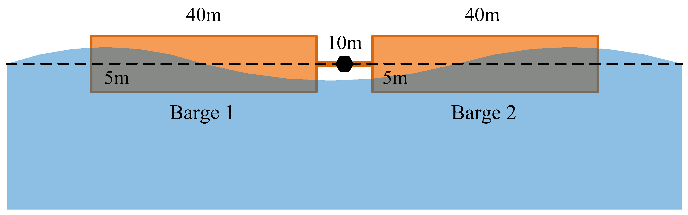


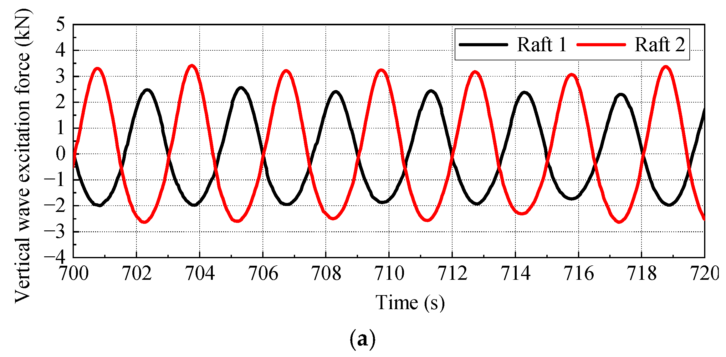
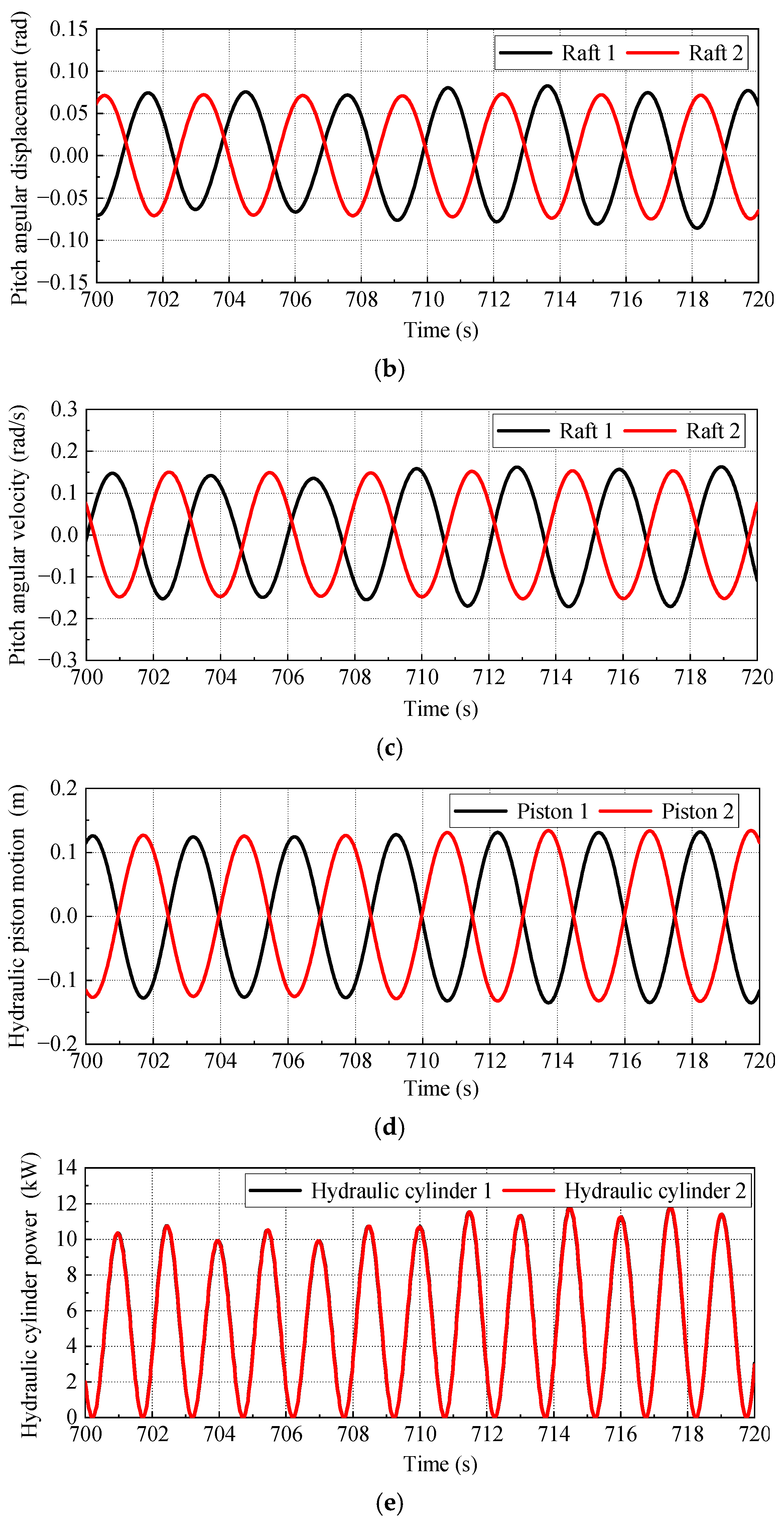


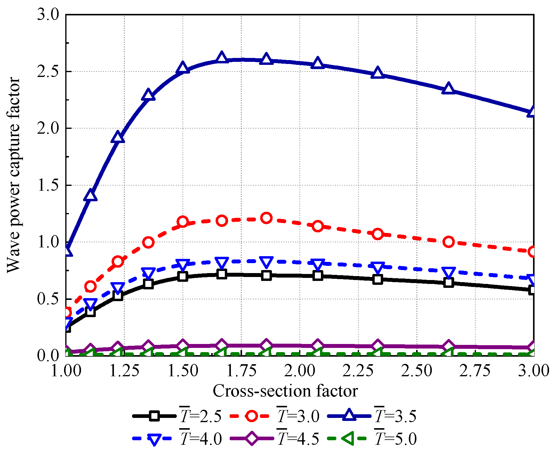


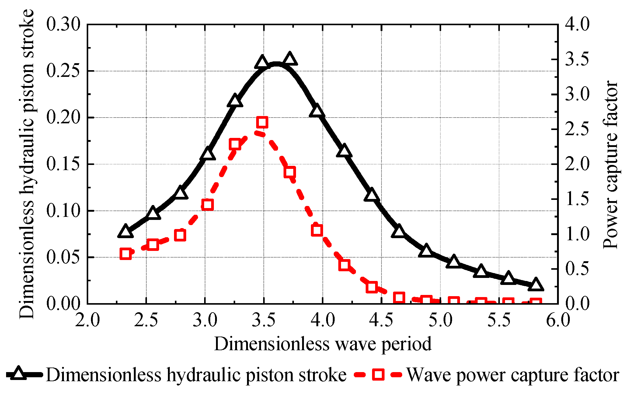
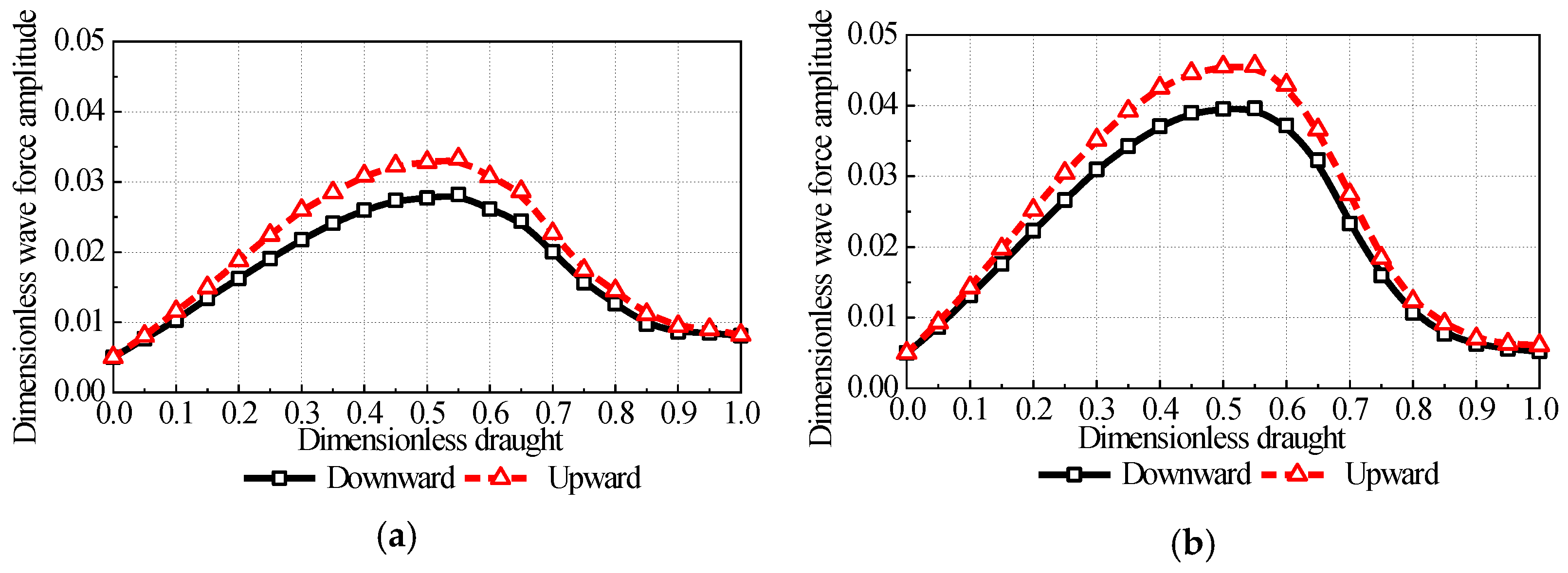

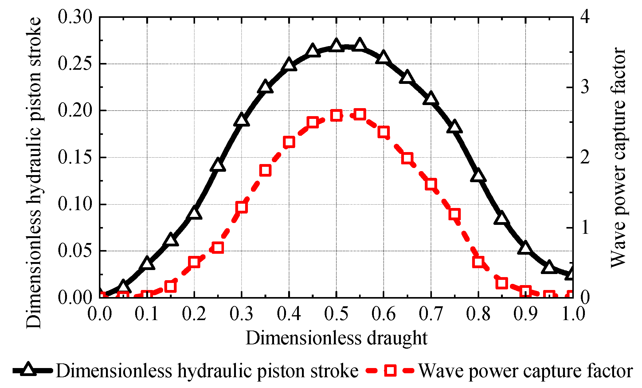


