Article

Water-Tank and Semi-Field Experimental Investigation of a Hose Net Fish-Hauling Device for Next-Generation Set-Net Fishing

1
Department of Systems Design for Ocean-Space, Faculty of Engineering, Yokohama National University, 79-5 Tokiwadai, Hodogaya-ku, Yokohama 240-8501, Japan
2
Institute of Industrial Science, The University of Tokyo, 5-1-5 Kashiwanoha, Chiba 277-8574, Japan
3
Graduate School of Engineering, The University of Tokyo, 5-1-5 Kashiwanoha, Chiba 277-8574, Japan
*
Author to whom correspondence should be addressed.
J. Mar. Sci. Eng. 2024, 12(1), 44; https://doi.org/10.3390/jmse12010044
Submission received: 6 November 2023 / Revised: 20 December 2023 / Accepted: 20 December 2023 / Published: 23 December 2023

Abstract

:
The flexible fire hose and net (hose net) is a novel fish-hauling device developed for set-net fishery. The hose net is placed inside the box chamber net, air is injected from one edge of the hose net, the hoses are inflated, and the buoyancy force is increased. The net floats up gradually, cornering the fish on the other edge. In previous studies, we have conducted a series of floating-up and sinking-down experiments to evaluate the performance of the hose net in calm water. In this study, aimed at the practical implementation of the hose net fish-hauling system, we conducted a water tank experiment and a semi-field test to confirm the operation of the hose net, which was installed inside a box chamber net model. The results demonstrated that the net could float up gradually in an ideal form and stretched on the surface of the box net. The time taken to float up processes varied with the air injected into the auxiliary hose and hose net, so that the motion of the hose net could be controlled by adjusting the air at different parts of practical operation. Furthermore, semi-field trials were conducted to verify its performance in the natural marine environment and its ability to capture schools of fish. Overall, this innovative hose net fish-hauling device is expected to be valuable for next-generation set-net fishing.

1. Introduction

The set-net, a passive fishing apparatus designed for the capture of fish, boasts a history that spans more than 300 years. As its name implies, set nets are positioned at fixed locations in the ocean to passively guide and capture schools of fish that travel with the tides. Set net fishery has achieved worldwide attention for its low impact on habitats and good fuel efficiency, as it does not require the high oil consumption of exploratory fishing and prevents fish below catchable size being released alive [1,2].
Comprising four primary components, namely, the leader net, playground, funnel, and box chamber net (bag net), the set net serves as a comprehensive apparatus (Figure 1 [3,4]). A school of fish first encounters the leader net and enters the playground along the leader net. It is then caught along the funnel as it enters the box chamber.
The process of guiding fish ensnared within a box chamber net towards the fishing vessel is referred to as ‘net-hauling operations’. Typically, the hauling system necessitates a significant workforce for the task of raising the nets. A summary of the technological advancements in net-hauling operations is presented in Figure 2 [5,6,7,8,9,10].
In the 1930s, efforts were made to devise a mechanism whereby a buoyant body was placed under a box chamber net and air was supplied to the buoyant body to sequentially lift the box chamber net and thus herd in the fish. Regrettably, this concept never materialized into practical application [5]. From the 1950s onwards, auxiliary machines such as catch haulers were introduced to reduce the reliance on manpower and labor, a method that continues to this day [6]. Nevertheless, the necessity for further enhancements in manpower and labor savings remains evident. In 1984, Fukahori [7] introduced a net-lifting system using a rubber hose and conducted experiments in the sea, but this system was not widely used due to high maintenance costs and difficulties handling it in the field. Kitazawa et al. [8] embarked on the development an inexpensive net lifting system using flexible hoses, but this type had many connection points, and a simpler method was desired from a manufacturing point of view. All of these approaches involved raising the elevation of box chamber nets to guide schools of fish, requiring considerable buoyancy to achieve this task. In cases of malfunction in the net-lifting apparatus, the raising of box chamber nets proved to be a challenging endeavor. In addition, the use of pontoons to lift the nets has been considered as a passive fishing method similar to set net fishing, but it is considered difficult to implement due to the different structure of the set net [11,12].
Since 2015, significant strides have been made in the integration of cutting-edge technologies into set net fishing, owing to advancements in sensing, communication, robotics, and related fields. For instance, technology has been put into practical use that allows Ultrasonic Fish Finder to be installed inside nets to ascertain the status of fish entering the net. This has made it possible to conduct operations according to the fishing conditions [13]. Regarding maintenance, underwater drones have made it possible to visually check set-net fixing ropes after a typhoon has passed, enabling responsive actions based on the observed conditions [14]. Furthermore, a specialized platform has been developed, featuring power generation, current velocity measurement, and communication functionalities specifically designed to suit set-net fishing [15]. The latest research is using machine learning to develop a predictive model for fish catches that can support decision-making on staffing onboard and onshore operations, as well as decisions on whether to suspend fishing or change nets [16].
Additionally, in the view of biodiversity conservation, fish species selection and catch management are required. Several studies have been conducted, including research on optimizing mesh sizes for set-net [17], analyzing the behavioral characteristics of fish within these nets and estimating fish species [18,19], and the development of real-time monitoring and estimation systems tailored for set net fishing [20]. Notably, research is underway to understand the biological behavior of sea turtles in set-net [21]. However, despite these advancements, the traditional fish-hauling method from the 1950s is still in use.
From 2018 to 2020, our team introduced a parallel hose net to optimize the use of flexible hoses and minimize the number of connection points between the hoses, as shown in Figure 2. The parallel hose net is installed within the box chamber net. By supplying air to the hose, the parallel hose net gains buoyancy and guides schools of fish into the fish trap [9]. Notably, our fish school guidance system eliminates the need to raise the box net, thereby reducing the required buoyancy of the hose net. The hose net obviates the necessity of extracting the box net during maintenance, only the hose net needs to be removed and repaired. Furthermore, as the hose can be remotely manipulated for air intake and exhaust from a remote location, this system facilitates automation and allows the net to float at any given time. A series of water tank experiments and catch-harvesting tests were conducted to evaluate the performance of the hose net [4]. Through these experiments, the parallel hose net successfully floated to guide fish into the scoop-up zone. However, there were still several concerns that the parallel hose net would interfere with the box chamber net, preventing it from floating up smoothly, and that fish might escape through the gap between the parallel hose net and the box chamber net.
The existing studies mentioned above still focus on the control of the floating and sinking speed of a single hose net in still water, without considering the effect of the box chamber box net and the behaviour of the fish school during the floating/sinking process, though these are important factors that affect the catching performance of a hose net in a set net in practice.
The aims of the present research are follows as:
Evaluate and improve the floating-up condition of the hose net considering the effect of the box net.
Assess the floating-up condition of the hose net under real sea conditions.
Examine catch-hauling for the live fishes.
This study involved water tank and semi-field experiments, to address concerns and enhance the practical applicability of the hose net. At first, the experiments in the water tank were conducted to measure the shape of the hose net as it floated up, both with and without the auxiliary hose. The hose net was placed inside the box chamber net to assess its performance. In the semi-field experiment, we positioned the hose net inside the box net to assess its buoyancy in the real sea, considering the influence of waves and water flows. Simultaneously, catch-harvesting tests using live fish were carried out to evaluate the efficiency and effectiveness of the hose net.
The hose net fish-hauling device is the core technology used in Next-Generation Set-net Fishing. When combined with Ultrasonic Fish Finder [13], fish prediction technology [18,19], and offshore power generation, it is expected to realize complete automation of set-net fishing. It is also expected to be used for fish stock selection, protection of endangered species, and efficient catch management. The hose-net aligns with SDG 14, which aims to “conserve and sustainably use the oceans, seas, and marine resources for sustainable development”.

2. Models and Experimental Method

The hose net ascends in a shape designed to drive fish, and it naturally settles due to the exhaust process after the harvesting operations. In this study, we utilized a model consisting of the box chamber net of a large set net. The physical net used for practical applications has dimensions of 60 m in length, 36 m in width, and 30 m in depth. For the purpose of water tank testing and semi-field experiments, a scaled-down 1/10-size hose net model was used within the box chamber net.

2.1. Hoes Net Model

The details of the hose net are presented in Table 1 and Figure 3. The hoses used for both the supply and exhaust sections of the hose net are fabricated from flexible fire hoses, consisting of a polyester thread and an inner polyurethane resin. Prior to deployment, a preliminary calculation was made to determine the required buoyancy, which resulted in the selection of a 25 mm-diameter hose. The estimated diameter of the actual hose of the hose net is 150 mm, so a hose with 1/6 scale diameter was employed. Ideally, a 1/10 scale ratio, consistent with the models of the box net and hose net, would have been preferred. However, due to the unavailability of suitable materials, a scale ratio of 1/6 was adopted. The volume ratio was reduced to 1/216. Additional weights were attached to the hose net to ensure that the net would descend naturally when the air was exhausted. The total weight of the hose net, including these extra weights, is 255.47 N. Conversely, when the interior of the flexible hose was filled with air, the maximum buoyancy it could generate amounted to 286.36 N.
In addition, as shown in Figure 3, two auxiliary hoses 100 mm in diameter were added at the front (input air side) and rear ends of the hose net. The inclusion of the front auxiliary hose was intended to ensure a secure closure of the slope net and to stabilize the floating-up shape of the hose net. This measure was taken to address the scenario where, if the hose net were to maintain a slope underwater, it might not ascend entirely from the front side. The auxiliary hose at the rear side could help to close the capture net.

2.2. Box Chamber Net Model

As it is not efficient to reproduce the many buoys that are the buoyant material of the box net in the experiment, we created the buoyant part by using hoses with a diameter of 100 mm instead, as shown in Figure 4 and Table 2. These hoses were interconnected using caps and air pipes.
The netting has a mesh size of 90 mm, with a twine diameter of 4 mm. In the process of creating the 1/10 scale model, it was determined that scaling down the mesh size and twine diameter to 1/10 would present challenges in fabricating the net material. It was therefore decided to use the same fabric as the actual material as a model for the netting.

2.3. Setup of Models in the Water Tank

The water tank tests were conducted in the ocean engineering basin at the University of Tokyo. The dimensions of the water tank measure 50 m in length and 10 m in width, and it has a water depth of 5 m. The water tank is equipped with a floor that can be elevated to adjust the water depth, offering a range from 0.4 m to 5.0 m. For our experiments, the water depth was maintained at 3.0 m in the hose net test and changed to 4.6 m when the hose net was set in the box net, to facilitate the full deployment of the box net. To minimize the space between the hose net and the box net, the hose net was attached to a weighted line (lead rope) at four distinct points to restrict horizontal movement (Figure 5). To capture the shape of the hose net as it ascended, depth meters were strategically positioned at nine locations. The depth meters were DEFI2-D10 from JFE Advantech Co., Ltd. (Nishinomiya, Hyogo, Japan). Their measurement range is 0~1 MPa, 0~100 m, their resolution is 0.0001 MPa, 0.01 m, and their accuracy is ±1.0%FS at 25 °C. While we contemplated installing depth meters in the width direction as well, it was observed that the shape remained relatively constant during floating-up. Consequently, data acquisition was limited to the longitudinal direction, with readings recorded at 1 s intervals. The specific installation locations are indicated by blue dots in Figure 5. The speed of the injected air is 0.57 L/s from the air compressor.
In the operations, the configuration of the hose net is mainly determined by the time taken to inject air into the hoses. Furthermore, the presence of auxiliary hoses, which offer substantial buoyancy, plays a pivotal role in supporting the hose net’s ascent. To comprehensively evaluate the effects of these factors, experiments were conducted both with and without the presence of auxiliary hoses. The influence of the box net was also taken into account.
The two-dimensional geometry of the hose net was approximated by analyzing depth meter measurements taken at several positions, which provided both X and Z coordinates for the hose net. The Z-coordinates were directly acquired from the depth meters, while the X-coordinates of these measurement points were derived by assuming that all horizontal displacements occurred exclusively in the X-direction and that a straight-line connection existed between any two given (Figure 6). Using the first point on the air input side as the reference point (origin), it was feasible to calculate subsequent horizontal displacements by determining the distance between any two depth-meter positions [4].

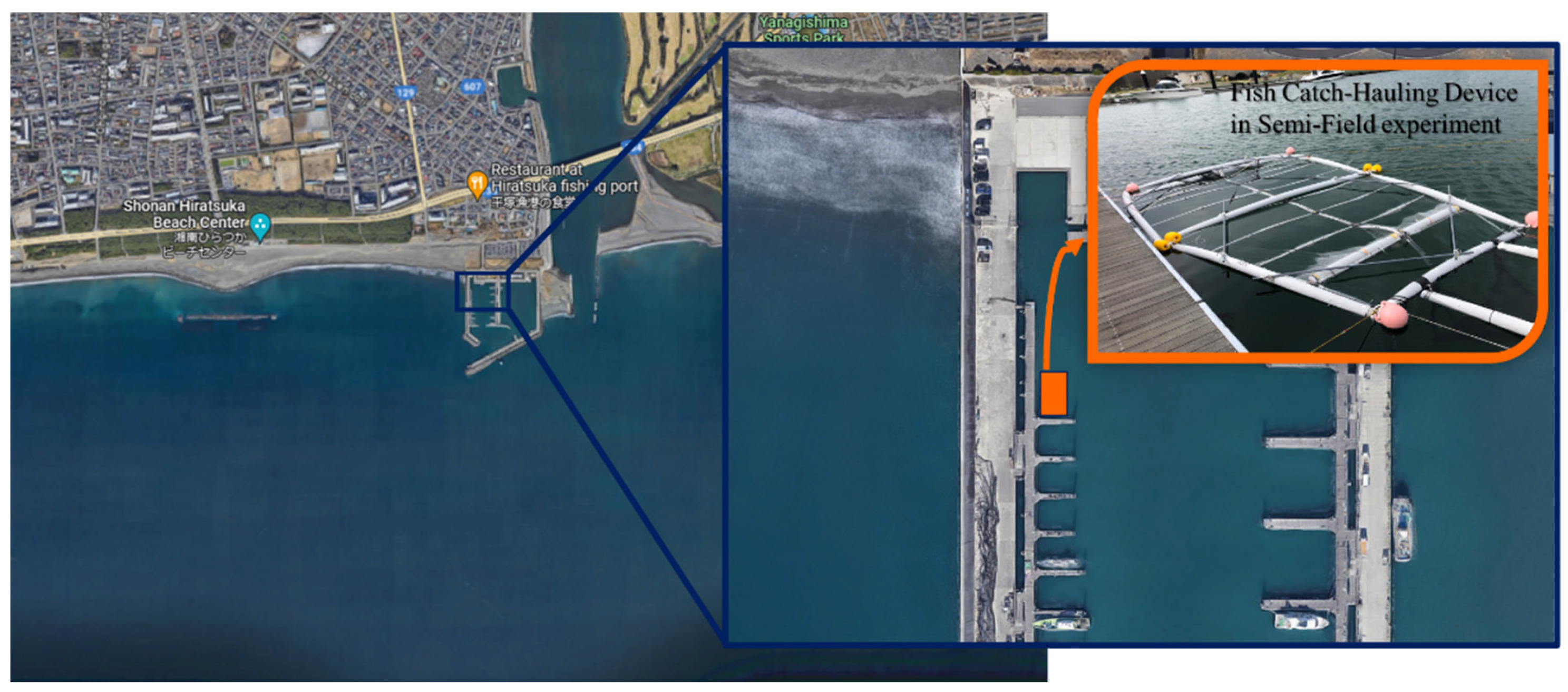
2.4. Semi-Field Experiment

Set nets are typically positioned several hundred meters or more from the coastline and are subject to the influences of natural elements like waves and currents. Therefore, it is imperative not only to conduct experiments in the water tank but also to gain insight into their behavior in natural surroundings. However, due to the practical constraints arising from the size of the model used in this study, conducting experiments in the open ocean proved to be challenging. As a result, the experiments were carried out in a relatively calm natural environment. The semi-field experiment was executed at a corner of the pier located at Hiratsuka New Port in Hiratsuka City, Kanagawa prefecture, Japan, as shown in Figure 7. The same models and set-up methods used in the water tank test were replicated for this experiment. Moreover, depth meters were positioned at identical locations within the hose net, as shown in Figure 5.

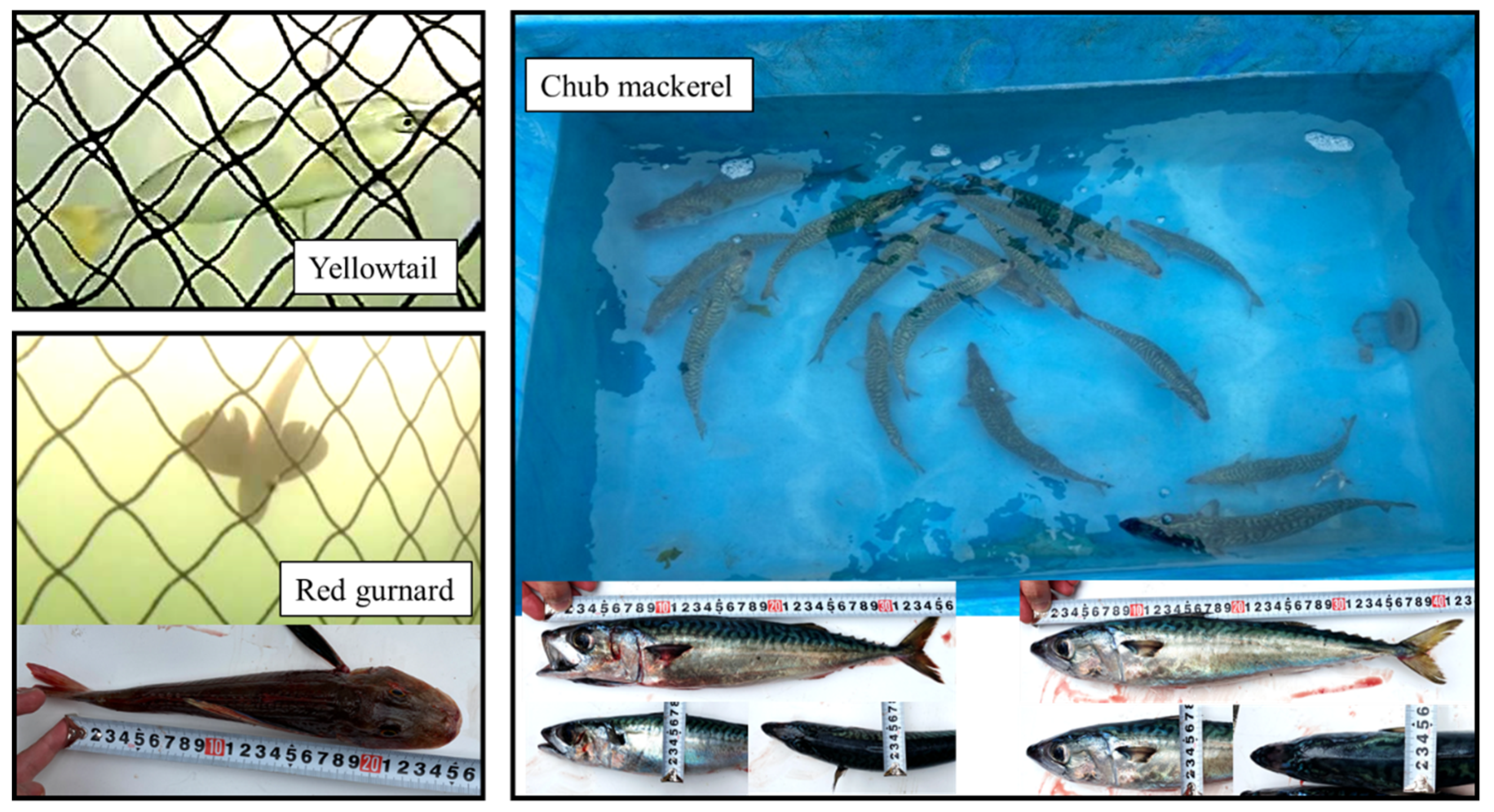
2.5. Catch-Hauling Tests

In order to assess the catch-hauling performance, experiments were conducted using live fish. Specifically, we obtained 2 yellowtails (Seriola quinqueradiata), 2 red gurnards (Chelidonichthys cuculus), and 16 Chub mackerels (Scomber japonicus) from set nets located in the Hiratsuka open sea, as depicted in Figure 8 and Table 3. The experiment included fish within a body length range of 270 mm to 422 mm.

3. Results and Discusses of Water Tank Experiment

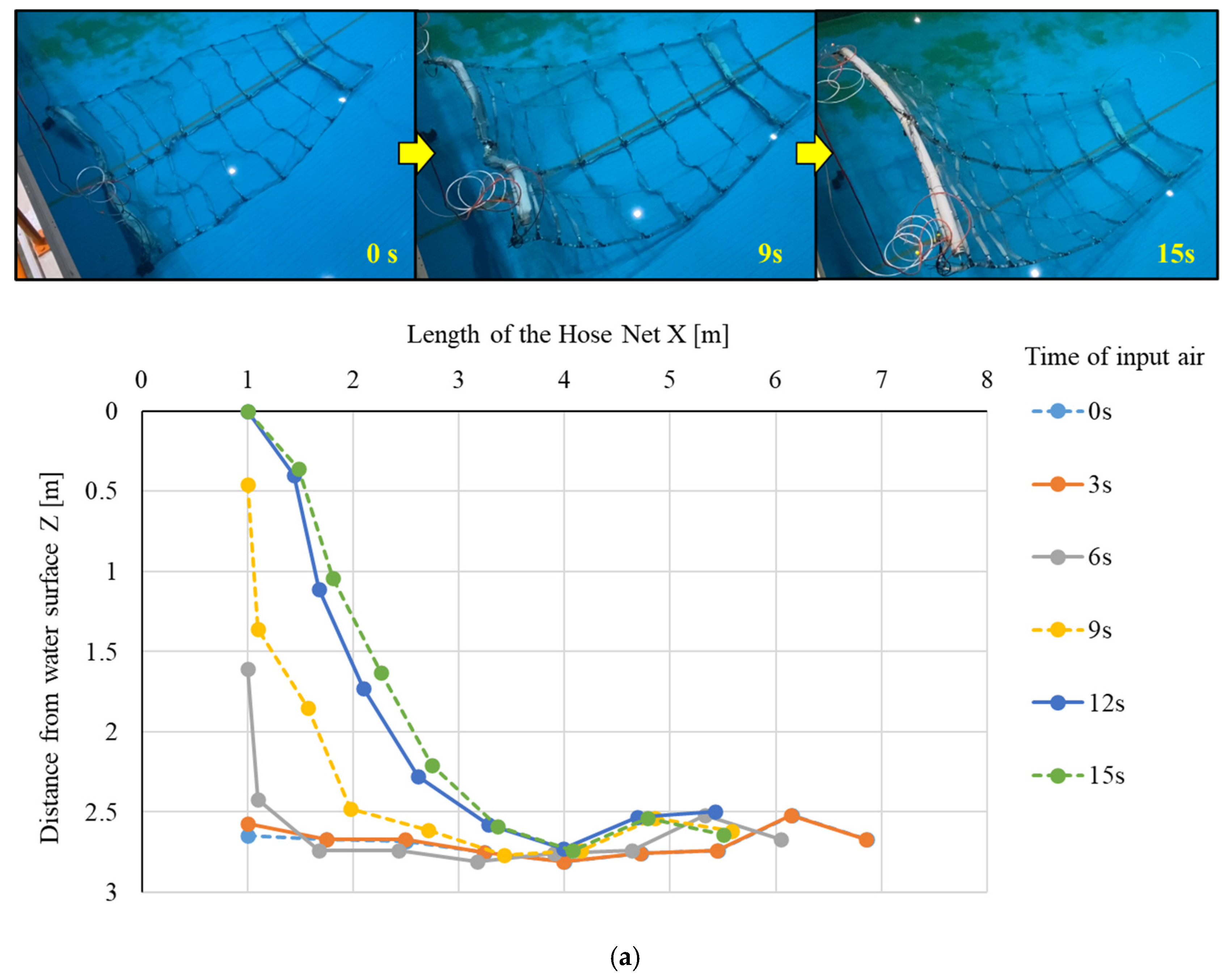
3.1. Single Hose Net Model

Figure 9 shows the selected two-dimensional shape change results of the hose net’s flotation status. The gradual ascent of the hose net, facilitated by air injection, is a key feature that can be harnessed to drive and corner the fish. In Figure 9b, we present the two-dimensional deformation of the hose net during its gradual ascent at various time intervals. The air injection rate was maintained at 0.57 L/s, powered by the air compressor. It is noteworthy that the hose net started to rise from the air input side at 10 s. At 40 s, the air input side reached the water surface while the rear side remained at the bottom. As air injection continued, the front segment of the hose net gradually rose to the surface, and the underwater part was thought to drive fish toward the capture net. Similar flotation conditions have been confirmed with another model [4]. The entire hose net reached the water’s surface at 50 s. However, it should be noted that in the final deformation at the water surface, some areas may not have ascended entirely to the water surface. Additionally, if the bottom of the box net features irregularities, there is a possibility that the hose net may not float up uniformly from the air input side.
Regardless of the shape of the bottom of the box chamber net, we explored using auxiliary hoses to enhance buoyancy on the air input side to ensure a consistent ascent from that direction. Additionally, another auxiliary hose was positioned at the rear to facilitate the closure of the box net and the cornering of fish towards the capture net. The air injection was divided into three steps. In the first step, air was injected solely into the auxiliary hose on the air input side; in the second step, air was injected into the hose net; and in the third step, air was injected into the auxiliary hose on the rear side.
Figure 10a presents the time series of the first step. During this phase, when the air was exclusively injected into the auxiliary hose, the auxiliary hose along with the hose net on the air input side ascended to the water’s surface within 15 s, while the rear side remained on the bottom. This implies that the box net could be closed within 50% of the time compared to using the hose net alone. Following the completion of the first step, air was injected into the hose net. It took 50 s for the hose net to ascend entirely to the surface, almost the same amount of time as that taken by hose net without the auxiliary hose. It is also evident that the shape of the hose net during flotation is smoother compared to what is depicted in Figure 9. The third step, the air injection into the auxiliary hose on the rear side, started at 50 s to assist the floating-up on the rear side.

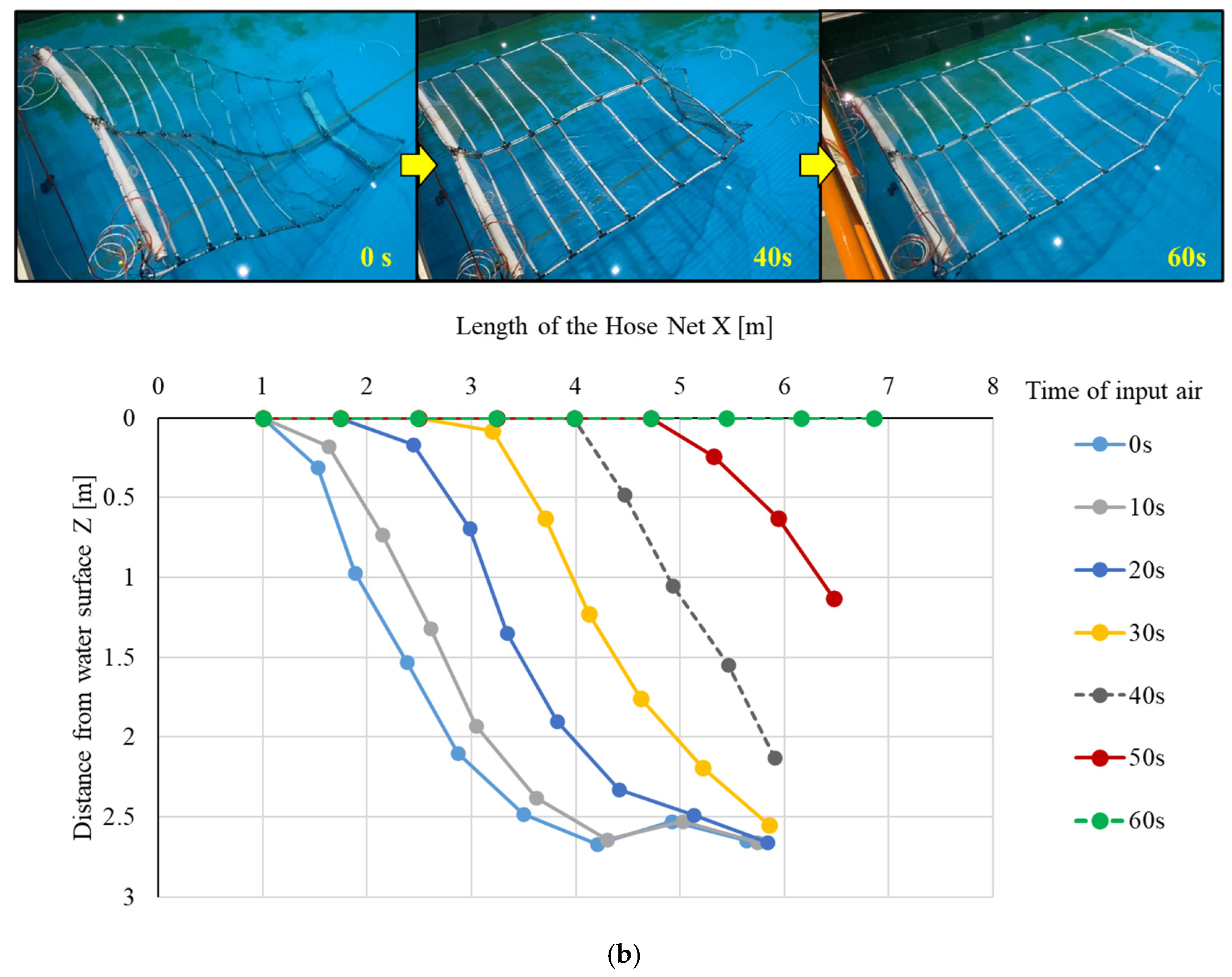
3.2. Hose Net Set with Box Net

As presented in Figure 5, lead ropes were installed and connected to the hose net. These lead ropes are ropes fitted with low-friction threads and affixed to weights, suspended from the inner corners of the box net. Their purpose is to minimize horizontal displacement when subjected to external forces. Initially, the hose net was placed inside the box net without lead ropes, and flotation tests were conducted. However, the hose net encountered difficulties when it became entangled within the box net, impeding a smooth ascent. In an effort to stabilize the horizontal position of the hose net and reduce contact with the box net, lead ropes were introduced.
Figure 11 shows the results of time series of the hose net when it was positioned inside the box net. The experiments confirmed that stable flotation shapes were maintained even inside the box net. During the first step, when air was injected into the auxiliary hose, the hose net on the air input side ascended to the water’s surface within 15 s, as was the case without the box net. As is clear from these graphs, the parallel hose net floated smoothly without interfering with the box chamber net. This outcome can be attributed to the substantial buoyancy provided by the auxiliary hose, which mitigated the friction induced by the lead ropes and minimized the influence of the box net. In the second step, the floating time of hose net was 50 s, the same as the alone hose net. In the third step, the rear side of the hose net could be helped to float up to the water surface. Overall, these experiments reaffirmed the efficacy of this system, even when placed inside a box net. However, it should be noted that in actual operation, unlike in still water, strong sea currents may cause the box net to deform [22]. The effects of strong currents and waves on the deformation of the box net and the changes in posture during the floating/sinking process of the hose net are worthy of further investigation in future work.

4. Results and Discussion of Semi-Field Experiments

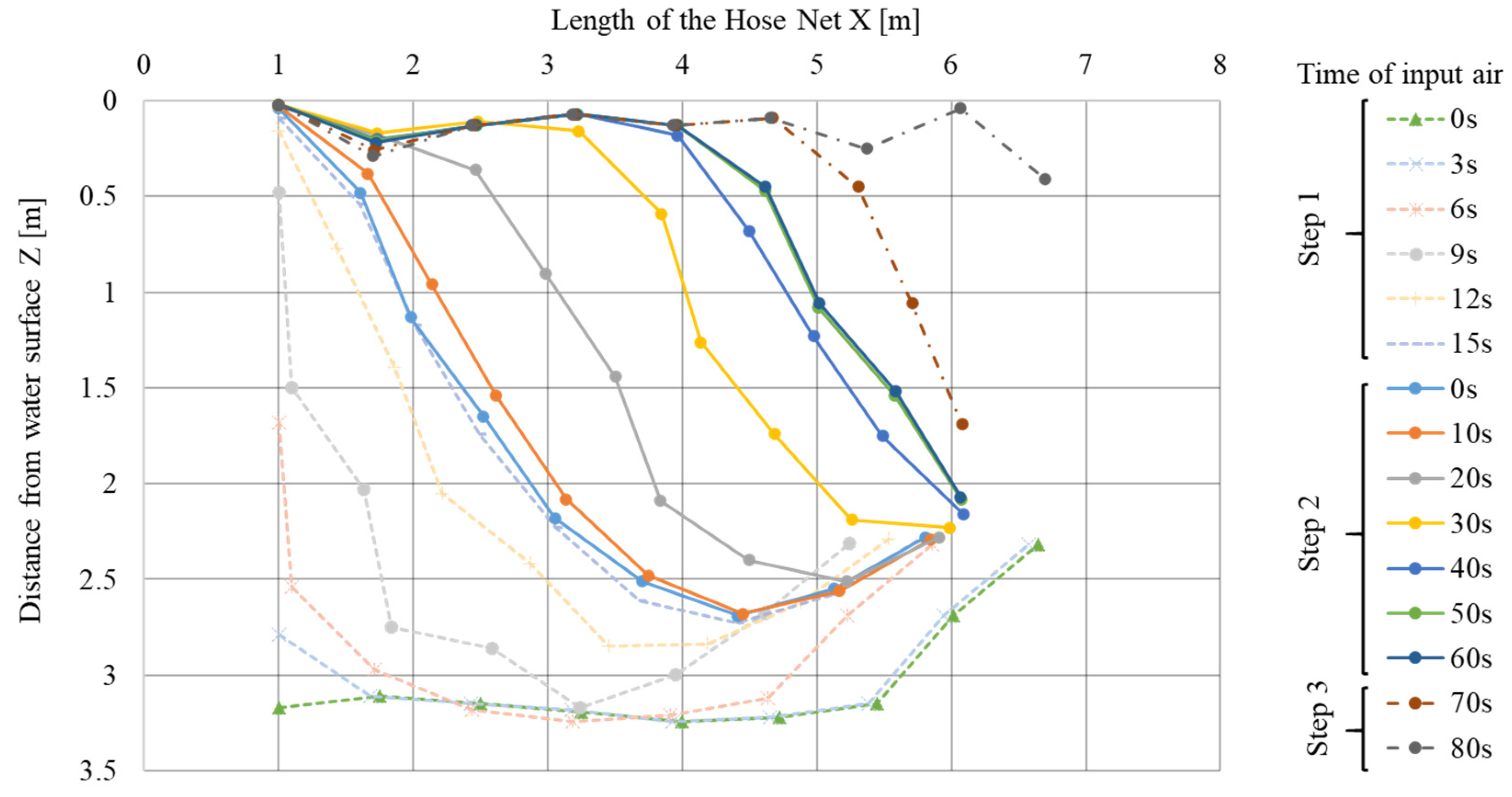
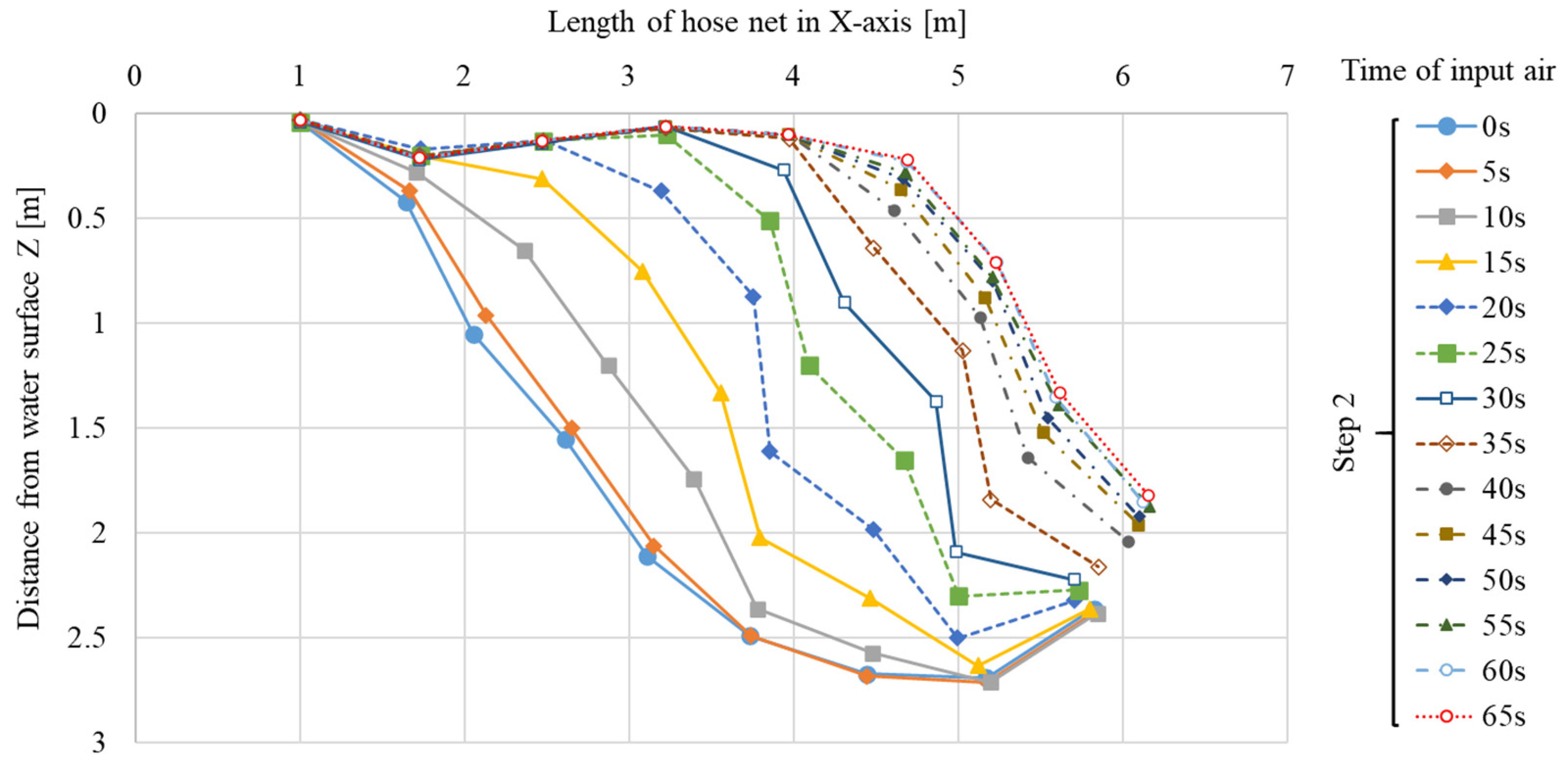
4.1. Floating-Up Performance of Hose Net

In the semi-field experiment, the same model was employed, and it was positioned at a designated corner of Hiratsuka New Port for flotation testing, as shown in Figure 7.
Given the location within a fishing port, the significant wave height during the actual measurement period was 0.05 m. Furthermore, the recorded results of the flow speed in the surrounding area during the experiment are illustrated in Figure 12. To statistically calculate the flow velocity, first, the average value and standard deviation were calculated. Then, the average value and standard deviation were recalculated considering only the observed values within the range of “average value ± 3 × standard deviation”. This process was repeated five times to converge the average value and standard deviation. The maximum flow remained below 17.7 cm/s, with an average flow speed of 6.6 cm/s.
Figure 13 demonstrates the two-dimensional defromation results, which are consistent with those observed in the water tank experiment in Step 2. In this experiment, which was conducted under specific natural conditions involving waves and currents, there were no problems with the floating/sinking operations of the hose net. Although this was a model experiment conducted under distinct natural conditions, it successfully validated the functionality of the hose net, even in real sea conditions. Unfortunately, the deformation changes in the box chamber net were not monitored during this experiment. In future work, it is recommended to provide more reliable technical support for the field deployment of the hose net by investigating the floating/sinking performance of the hose net while monitoring the deformation of the box chamber net [22].

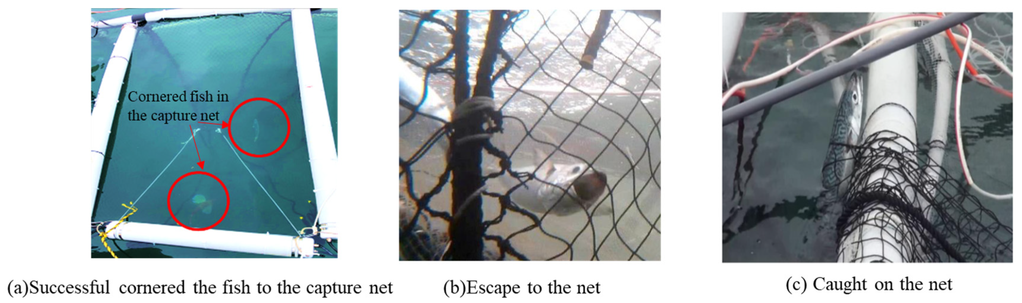
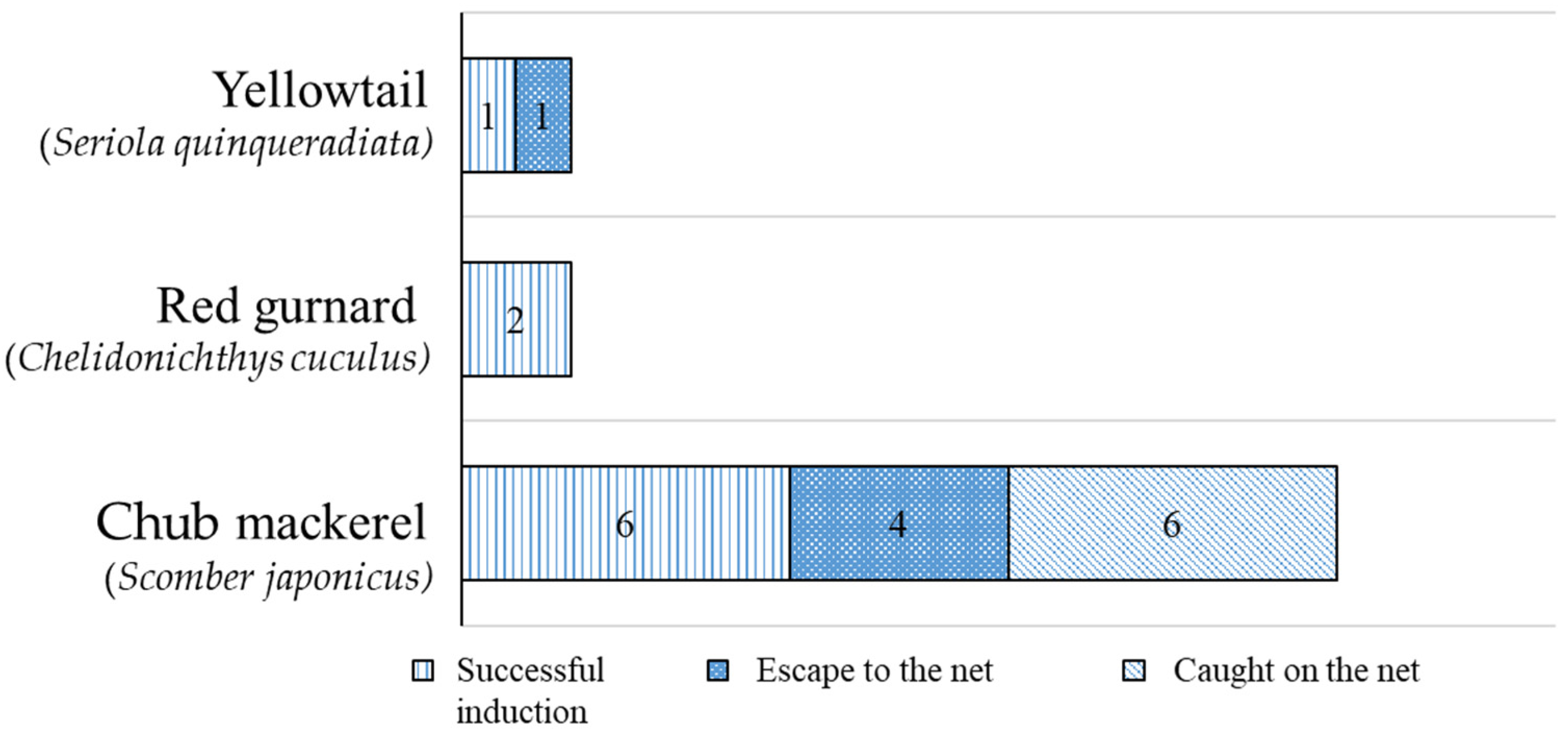
4.2. Catch-Hauling Performances

To assess the catch-hauling performance, live fish were used in our experiments. Specifically, we employed 16 chub mackerels (Scomber japonicus), 2 red gurnards (Chelidonichthys cuculus), and 2 yellowtails (Seriola quinqueradiata) captured from set nets located off the coast of Hiratsuka.
Initially, a limited number of catch-hauling trials were carried out using two red gurnards and two yellowtails. During these experiments, one red gurnard and two yellowtails were successfully cornered into the capture net, as depicted in Figure 14a. However, one red gurnard managed to escape outside the box net through a gap between the hoses and the hose connection. We then conducted an induction experiment with the remaining 16 mackerel. The box net had a larger mesh size, and four fish swiftly passed through the net on introduction (Figure 14b), while six fish became ensnared in the net’s mesh (Figure 14c). Consequently, six mackerel were effectively introduced into the system.
In summary, our catch-hauling experiments yielded positive results as shown in Figure 15, demonstrating that the system was effective in driving and cornering fish into the capture net, with the exception of fish smaller than the mesh size of the box chamber net that escaped between the nets.
The results of the semi-field experiments have confirmed the functionality of this hose net system under natural conditions, including the presence of waves and currents. The flotation shape of the hose net remained stable, ensuring a smooth ascent without interference from the box net, ultimately enabling efficient fish guiding. While the primary objective of the auxiliary hose is to stabilize the hose net’s shape during flotation, it also plays a vital role in maintaining system performance in the face of waves and currents. It is important to note that the sea areas where set nets are typically installed often feature more challenging natural conditions than those observed in this experiment. Further real-world experience in open ocean environments will be essential to future research. In addition, our studies only focused on the box chamber net part. The changes in the behavioral characteristics of fish school throughout the whole set net structure are also a very interesting and challenging topic [23,24,25]. The control of the hose net will be our next research direction in combination with the behavioral characteristics of schools of fish.
Furthermore, the proposed hose–net device can be used not only in the fishing industry, but also in the floating and sinking operations of composite tanks for storing oil and natural gas on the seabed [26,27].

5. Conclusions

In a past study, a novel automated fish-harvesting device using a flexible fire hose combined cover net was proposed, and a series of water tank experiments and catch-harvesting tests were conducted to evaluate the performance of the hose net [4]. In this study, a water tank and semi-field experiment was conducted in order to uncover issues and improve the hose net in an aim for practical application. First, the shape of the hose net when it floats up was confirmed with and without an auxiliary hose in the water tank. And we set the hose net inside of the box net to check the effort of the box net. Finally, catch-harvesting tests were conducted to evaluate the performance of this hose net.
The following results were obtained:
The improved hose net gradually floated up in a shape configuration with a large angle of inclination, which means the configuration curve was feasible for cornering and harvesting the fish.
The addtition of the auxiliary hose in the hose net reduced the floating time required to close the box net, and it definitely floated up from the air input side. By injecting air in stages, it was possible to control the shape when driving the fish.
When the hose net was set in the box net, lead ropes were necessary to maintain the horizontal position.
In the semi-field experiment, it was confirmed that the hose net floated in the box net in the same shape as in the water tank experiment even under national conditions of waves and flows.
In the live fish test, there were no fish left behind on the floating hose net or escaping through the gap between the hose net and the box net, indicating that it was possible to drive fish to the capture net.
Overall, these results indicate that the hose net fish catch-harvesting system was able to drive the fish into the box net, demonstrating the strong practicality of the system. Notably, when integrated with an ultrasonic fish finder, fish prediction technology, and offshore power generation, this system is poised to achieve full automation in set-net fishing. Additionally, it is anticipated to play a pivotal role in fish stock selection, safeguarding endangered species, and optimizing catch management practices for Next-Generation Set-net Fishing.
The following issues still remain obstacles to practical application. It is necessary to examine the operational performance in high waves and tidal currents. There is also the issue of how to install the air supply system and maintain the hose nets. The current hose is made from commercially available fire hoses, and as it is a general-purpose product, costs can be kept down. It can withstand water pressure up to 30 m. When operating at deeper water depths, it is necessary to investigate the limits of water pressure. We will plan to install the hose net in a super small-size set-net operated in actual waters and aim for long-term operation by streamlining operating methods, conducting durability tests, and examining the effects of deposits.

Author Contributions

Conceptualization, Q.L., Y.M. and D.F.; methodology, Q.L., D.K. and Y.M.; software, D.F. and S.D.; formal analysis, D.F., Q.L. and S.D.; investigation, Q.L., D.F., S.D. and Y.M.; data curation, Q.L.; writing—original draft preparation, Q.L., D.F. and S.D.; writing—review and editing, D.K.; visualization, D.F. and S.D.; supervision, D.K.; project administration, D.K.; funding acquisition, D.K. All authors have read and agreed to the published version of the manuscript.

Funding

This work was supported by JSPS KAKENHI Grant Number JP1801633.

Institutional Review Board Statement

The animal experiments were reviewed and approved by the Experimental Animal Care and Use Committee of the University of Tokyo (approval code: DO 01-08).

Informed Consent Statement

Not applicable.

Data Availability Statement

The data are presented in the paper.

Acknowledgments

We would like to thank the staff of the Hiratsuka Fisheries Cooperative Association for their efforts in the semi-field experiment. The model used in this study was manufactured and provided by NITTO SEIMO Co., Ltd. (Hokuto City, Hokkaido, Japan). I would like to write here to express my gratitude.

Conflicts of Interest

The authors declare no conflict of interest.

References

  1. He, P.G.; Chopin, F.; Suuronen, P.; Ferro, R.S.T.; Lansley, J. Classification and Illustrated Definition of Fishing Gears; FAO Fisheries and Aquaculture Technical Paper No. 672; FAO: Rome, Italy, 2021. [Google Scholar]
  2. He, P.G.; Inoue, Y. Large-scale fish traps: Gear design, fish behavior, and conservation challenges. In Behavior of Marine Fishes: Capture Processes and Conservation Challenges; He, P., Ed.; Wiley-Blackwell: Ames, IA, USA, 2010; pp. 159–181. [Google Scholar]
  3. Ministry of Agriculture, Forestry and Fisheries of Japan. Available online: https://www.maff.go.jp/j/tokei/census/gyocen_illust2.html (accessed on 30 October 2023).
  4. Li, Q.; Li, Y.; Dong, S.C.; Mizukami, Y.; Han, J.L.; Yoshida, T.; Kitazawa, D. Performance and Feasibility Study of a Novel Automated Catch-Hauling Device Using a Flexible Hose Net Structure in Set-Net. J. Mar. Sci. Eng. 2021, 9, 1015. [Google Scholar] [CrossRef]
  5. Takayama, I. Set-net Floating experiment. Sci. Rep. Fish. Res. Inst. 1931, 2, 1–16. [Google Scholar]
  6. Miyamoto, S. Mechanical Net hauling of Set-net. Bull. Jpn. Soc. Sci. Fish. 1971, 37, 233–236. Available online: https://www.jstage.jst.go.jp/article/suisan1932/37/3/37_3_233/_pdf (accessed on 19 December 2023). (Translated from Japanese). [CrossRef]
  7. Fukahori, K.; Kasutani, M.; Nishenokubi, H. On the Development of an Automatic Setnet. Bull. Fac. Fish. Nagasaki Univ. 1988, 64, 45–51. [Google Scholar]
  8. Zhang, J.B.; Dohi, M.; Yoshida, T.; Kitazawa, D. Investigating the utilization of polyethylene pipe for automated hauling system in set net fishery. Ocean Eng. 2021, 233, 109192. [Google Scholar] [CrossRef]
  9. Li, Y.; Li, Q.; Mizukami, Y.; Yoshida, T.; Kitazawa, D. Study on the performance of the flexible hose net used in automated net-hauling system. Conf. Proc. Jpn. Soc. Nav. Archit. Ocean. Eng. 2019, 29, 549–553. [Google Scholar] [CrossRef]
  10. Fisheries Agency: The 1st Technology Workshop of Set Net Fishery. Available online: https://www.jfa.maff.go.jp/j/study/kenkyusidoka/teichi.html (accessed on 12 May 2021).
  11. Suuronen, P.; Siira, A.; Kauppinen, T.; Riikonen, R.; Lehtonen, E.; Harjunpää, H. Reduction of seal-induced catch and gear damage by modification of trap-net design: Design principles for a seal-safe trap-net. Fish. Res. 2006, 79, 129–138. [Google Scholar] [CrossRef]
  12. Hemmingsson, M.; Fjälling, A.; Lunneryd, S.G. The pontoon trap: Description and function of a seal-safe trap-net. Fish. Res. 2008, 93, 357–359. [Google Scholar] [CrossRef]
  13. Hosokawa, T. Contributing to sustainable fishing: Visualization of fixed nets using fish finders. Aqua Cult. Bus. 2020, 57, 47–50. [Google Scholar]
  14. Wada, M. Smart Fisheries; Midori Shobo: Tokyo, Japan, 2022; pp. 126–127. ISBN 978-4-89531-781-8. [Google Scholar]
  15. Chiu, C.-C.; Liao, T.-L.; Chen, C.-H.; Li, H. An Innovative Designed Velocimeter Application for Set Net Fishery. J. Mar. Sci. Eng. 2023, 11, 1740. [Google Scholar] [CrossRef]
  16. Kokaki, Y.; Tawara, N.; Kobayashi, T.; Hashimoto, K.; Ogawa, T. Sequential Fish Catch Forecasting Using Bayesian State Space Models. In Proceedings of the 2018 24th International Conference on Pattern Recognition (ICPR), Beijing, China, 20–24 August 2018. [Google Scholar] [CrossRef]
  17. Frid, O.; Belmaker, J. Catch dynamics of set net fisheries in Israel. Fish. Res. 2019, 213, 1–11. [Google Scholar] [CrossRef]
  18. Kang, M.; Liu, J.; Hassan, R.B.B.R.; Fajaryanti, R.; Hwang, B. A preparatory study on fish behavioral properties in a set-net. J. Korean Soc. Fish. Ocean Technol. 2020, 56, 105–113. [Google Scholar] [CrossRef]
  19. Hirama, Y.; Yokoyama, S.; Yamashita, T.; Kawamura, H.; Suzuki, K.; Wada, M. Verification of Fish Species Estimation Model Based on Echo Sounder Image. In Proceedings of the 32nd Annual Conference of the Japanese Society for Artificial Intelligence, Kagoshima, Japan, 5–8 June 2018. [Google Scholar]
  20. Saville, R.; Hatanaka, K.; Wada, M. ICT application of real-time monitoring and estimation system for set-net fishery. In Proceedings of the OCEANS 2015-MTS/IEEE Washington, Washington, DC, USA, 19–22 October 2015. [Google Scholar] [CrossRef]
  21. Shiozawa, M.; Shiode, D.; Okuyama, J.; Hu, F.; Tokai, T. Behavioural characteristics of loggerhead turtles (Caretta caretta) in a submerged bag net of a setnet observed in a bycatch simulation and the development of a turtle releasing device. Aquat. Conserv. Mar. Freshw. Ecosyst. 2019, 29, 2107–2115. [Google Scholar] [CrossRef]
  22. Wan, R.; Guan, Q.L.; Li, Z.G.; Hu, F.X.; Dong, S.C.; You, X.X. Study on hydrodynamic performance of a set-net in current based on numerical simulation and physical model test. Ocean Eng. 2020, 195, 106660. [Google Scholar] [CrossRef]
  23. Takahashi, Y.; Komeyama, K. Simulation of the capture process in set net fishing using a fish-schooling behavior model. Fish Sci. 2020, 86, 971–983. [Google Scholar] [CrossRef]
  24. Takagi, T.; Moritomi, Y.; Iwata, J.; Nakamine, H.; Sannomiya, N. Mathematical model of fish schooling behaviour in a set-net. ICES J. Mar. Sci. 2004, 61, 1214–1223. [Google Scholar] [CrossRef]
  25. Uchida, K.; Ogawa, H.; Hasegawa, K.; Miyamoto, Y.; Noro, H.; Wada, Y.; Akiyama, S. Monitoring the behavior of young bluefin tuna Thunnus orientalis and yellowtail Seriola quinqueradiata in set nets using ultrasonic biotelemetry. Nippon Suisan Gakkaishi 2018, 84, 14–22. [Google Scholar] [CrossRef]
  26. Pimm, A.; Garvey, S.; Jong, M. Design and testing of energy bags for underwater compressed air energy storage. Energy 2014, 66, 496–508. [Google Scholar] [CrossRef]
  27. Chang, C.T.; Huang, P.T. A water balloon as an innovative energy storage medium. Polymers 2022, 14, 3396. [Google Scholar] [CrossRef] [PubMed]
Figure 1. Structure of a set-net [3,4].
Jmse 12 00044 g001
Figure 2. The operation method and technique development history of net-hauling.
Jmse 12 00044 g002
Figure 3. Structure of the newly developed hose net with auxiliary hoses.
Jmse 12 00044 g003
Figure 4. Structure of the box net.
Jmse 12 00044 g004
Figure 5. Water tank experiment setup ((a) side-view schematic of the experimental setup. (b) A photo taken during the experiment).
Jmse 12 00044 g005aJmse 12 00044 g005b
Figure 6. Estimating method of two-dimensional geometry of the hose net [4].
Jmse 12 00044 g006
Figure 7. The location of semi-field experiment.
Jmse 12 00044 g007
Figure 8. Live fish used in the catch-hauling tests.
Jmse 12 00044 g008
Figure 9. Two-dimensional deformation at different times of the hose net during floating up without auxiliary hose. (a) Photographs captured during the experiment. (b) Two-dimensional deformation.
Jmse 12 00044 g009
Figure 10. Selected two-dimensional deformation changes in the hose net during floating-up with auxiliary hose. (a) The 1st step: inject air to the auxiliary hose of air input side; (b) the 2nd and 3rd steps: inject air to the hose net and auxiliary hose of capture net side.
Jmse 12 00044 g010aJmse 12 00044 g010b
Figure 11. Selected two-dimensional deformation changes of the hose net during floating-up in the box net.
Jmse 12 00044 g011
Figure 12. Flow speed in the semi-field test.
Jmse 12 00044 g012
Figure 13. Two-dimensional deformation of the hose net during floating-up in the semi-field test.
Jmse 12 00044 g013
Figure 14. Fish images of catch-hauling test.
Jmse 12 00044 g014
Figure 15. Catch-hauling results in the semi-field test.
Jmse 12 00044 g015
Table 1. Physical parameters of the hose net model and actual hose net.
Items1/10 ModelActual Net
Hose NetAuxiliary Hose
Length (m)6.02.08
(In the front)
3.58
(In the rear side)
60.000
Width (m)3.6---36.000
Diameter of the hose (mm)25100150
Volume (L)2916289500
Maximum buoyancy (N)286.36161.31277.64116,548.70
Weight of the hose net (N)255.47143.91247.69---
Material density of hose
(kg/m3)
(Polyester and polyethylene)
1340134013401340
Material density of cover net (kg/m3)
(Polyester)
1380138013801380
Weight of the hose net (N)
Maximum buoyancy (N)
0.890.890.89---
Table 2. Physical parameters of the box net model and actual box net.
ItemsBox NetActual Net
Length (m)6.060
Width (m)3.636
Depth(m)3.030
Diameter of the float hose (mm)100--
Volume of floating hose(L)213--
Mesh size of the net (mm)9090
Diameter of the net twine diameter (mm)44
Material density of hose (kg/m3)
(Polyester and polyethylene)
13401340
Table 3. The size of experimental fish.
SpeciesYellowtailRed GurnardChub Mackerel
Body Length (cm)30.0~32.027.0~28.030.8~42.2
Body Width (cm)---5.0~5.54.0~4.8
Body height (cm)---4.8~5.05.5~7.0
Disclaimer/Publisher’s Note: The statements, opinions and data contained in all publications are solely those of the individual author(s) and contributor(s) and not of MDPI and/or the editor(s). MDPI and/or the editor(s) disclaim responsibility for any injury to people or property resulting from any ideas, methods, instructions or products referred to in the content.

