Article

Effects of Laying Depth and Pipe Arc Length on the Mechanical Performance of Large-Diameter Cold-Water Pipes during Float-and-Sink Installation

1
College of Safety and Ocean Engineering, China University of Petroleum-Beijing, Beijing 102249, China
2
State Key Laboratory of Hydroscience and Engineering, Department of Hydraulic Engineering, Tsinghua University, Beijing 100084, China
3
Southern Marine Science and Engineering Guangdong Laboratory (Zhanjiang), Zhanjiang 524005, China
4
Institute of Acoustics, Chinese Academy of Sciences, Beijing 100190, China
*
Author to whom correspondence should be addressed.
J. Mar. Sci. Eng. 2023, 11(8), 1520; https://doi.org/10.3390/jmse11081520
Submission received: 16 June 2023 / Revised: 23 July 2023 / Accepted: 27 July 2023 / Published: 30 July 2023
(This article belongs to the Special Issue Stability and Health Monitoring of Offshore Structures)

Abstract

:
The successful operation of a large-diameter cold water pipeline installation is crucial for harnessing the potential of ocean thermal energy conversion. However, there is a shortage of research focused on mechanical performance analysis during installation. This study establishes a pipeline response analysis model based on a nonlinear beam theory to elucidate the underlying mechanical behaviour. Employing the method of singular perturbation, the general solution for the exterior region of the pipeline, the solution at the boundary layer, and the valid solution across the entire domain are derived. A comparison with numerical solutions is conducted to validate the accuracy and effectiveness of the theoretical model. Based on the theoretical analysis, the influence of installation depth and pipeline curvature on the pipeline’s shape, tension, curvature, and stress is discussed. The results indicate that increasing the installation depth leads to intensified pipeline bending and significant deformation, reaching a maximum bending moment of 3.92 MN∙m at a distance of 50~100 m from the bottom of the pipeline. The results also show that, as the pipeline’s arc length increases from 0 to 100 m, the bending curvature, Von Mises stress, and bending stress exhibit a trend of initial growth followed by a decline, peaking at 7.45 MPa, and 6.83 Mpa, respectively, while the actual tension and axial tension decrease initially and then increase, reaching −0.17 MN and −0.17 MPa, respectively, at the maximum arc length. The findings of this study provide valuable insights for practical cold-water pipe installation and laying.

1. Introduction

Ocean Thermal Energy Conversion (OTEC) involves the extraction of a substantial volume of deep-sea cold water from depths exceeding 1000 m through a specialized conduit known as a cold-water pipe (CWP). This cold-water pipe plays a pivotal role in facilitating the complete evaporation of the liquid mass, thereby harnessing the requisite mechanical energy to drive a turbine and generate electricity at a level suitable for commercial power generation. Consequently, the effective length of the CWP can span an impressive range of 800 to 1200 m while boasting a diameter of up to 10 m [1]. As a result, the cold-water pipe emerges as the most critical and demanding component within OTEC installations. Simultaneously, the safe and effective installation and positioning of the CWP presents a significant technical challenge that must be overcome to ensure the successful operation of OTEC projects.
As a typical marine riser, chilled water pipes’ installation and laying methodology resemble that of risers. Deepwater pipelines are laid using either J-type applying or S-type laying techniques. J-type laying results in a greater bending radius of the pipeline from sea level to the seabed, positioning the landing point close to the pipe-laying vessel. This arrangement allows for easier monitoring, precise positioning, and less tension on the pipeline [2]. However, J-type laying exhibits lower speed and efficiency than S-type applying, with the latter being more stable [3]. Nevertheless, considering the structural characteristics of large-diameter chilled water pipes and the imposed restrictions on their maximum bending radius during installation and laying, foreign scholars have introduced a novel method: the Float and Sink Method [4,5]. The specific construction procedure is as follows: ① The pipe is towed with air and connected to the OTEC device using a winch and rope. Additional buoyant material required for transportation is subsequently removed. ② Seawater is gradually allowed to fill the pipe, while the bending curvature of the pipe is controlled by pulling it tightly from the installation vessel to regulate its descent. ③ Once the pipe attains its vertical position, the load is transferred from the installation vessel to the winch on the OTEC unit. ④ The Cold-Water Pipe (CWP) is elevated to its final position, and the ultimate connection is accomplished by an underwater robot, as depicted in Figure 1. The pipeline’s actual installation and laying process is influenced by dynamic characteristics, such as the laying depth and length. Therefore, comprehending the dynamic characteristics of the pipe and the factors that influence them during installation and laying holds significant importance in the design of large-diameter cold water pipe systems.
In installing and laying chilled water pipes, the inherent deformation characteristics involve large deflections, nonlinearities, and elastic deformations, falling within geometric nonlinear problems. The fundamental equation describing the pipe’s shape is a nonlinear equilibrium differential equation. The pipe installation and laying process analysis can be categorized into static analysis, quasi-static analysis, and dynamic analysis [6]. Static analysis methods are employed to analyze flexible pipes’ form and stress conditions using discontinuous laying techniques. Konuk [7], based on elastic rod theory, derived a static equilibrium formula for underwater pipelines using perturbation methods, effectively addressing the nonlinearities of submarine pipelines. Lenci and Callegari [8] proposed an improved approach to detect boundary layer phenomena based on classical contact network theory modifications, demonstrating its applicability in deepwater and ultra-deepwater installation and laying. Brown and Palmer [9] presented a solution method based on a catenary to determine the shape and stress of deepwater S-laid pipelines, albeit disregarding pipe stiffness. Using reinforced contact network theory, Gong et al. [10] established a balanced control differential equation for pipe fittings. They derived an equation for the pipeline configuration from the barge to the seabed, described the numerical iteration method for solving the pipe configuration, developed the corresponding program, and analyzed the effects of laying depth, pipe diameter, and length of the support frame on the pipe configuration. Winget and Huston [11] studied the dynamic issues caused by the interaction between flexible cables and pipelaying vessels by developing algorithms for kinematics, force systems, and control dynamics equations combined with the Runge–Kutta method. Santillan and Virgin [12] studied the effects of platform motion and vibration sensitivity on S-laid pipeline installation, analyzing the influence of total pipeline length, buoy position, and fixed height of attachment points on deflection and compared experiments and simulations. Wang et al. [13] developed a coupled dynamic model considering various influencing factors, based on the catenary theory and Morison equation, to determine the initial shape of flexible pipes and studied the emotional behaviors of axial tension, bending moment, and stress-strain during the laying process. They found that wave effects were most significant when wave direction interacted with ship width, wave height exceeded 2 m, and the spectral period was 8 s. Zan et al. [3] established a motion-coupling model for S-laid pipeline installation, considering the effects of vessel motion, surface waves, ocean currents, wind forces, pipeline dynamics, and contact between rollers and the pipeline. The Newmark method was used for the solution, and the results were validated by comparison with the OrcaFlex software, demonstrating a clear relationship between pipeline dynamic response and vessel motion. Xu et al. [14] developed a specialized finite element model (FEM) for S-laid deepwater pipeline installation, considering anomalous wave effects, vessel motion, interaction between the pipeline and support frame rollers, and cyclic contact between the pipeline and seabed soil. These scholars have demonstrated through theoretical analysis, numerical simulation, and experimental methods that the dynamic characteristics of pipelines during deepwater installation and laying directly influence the results and installation process of applying facilities. Therefore, to ensure the safe and effective installation and laying of large-diameter chilled water pipes, it is necessary to study the dynamic characteristics of these pipes during the process. Ghafouri et al. [15] used 3D stress distribution to extract the dynamic equations of fluid-structure interaction and solve the obtained Equation based on the state vector method. Zarastvand et al. [16] investigated the acoustic performance of the stiffened doubly curved shells based on a genetic algorithm. Alanazi et al. [17] studied buried pipelines under static loads using finite element analysis. The authors simulated different types of pipelines (steel, concrete, and 3D-printed concrete) with different thicknesses and soil conditions (sandy and cohesive, moist, and saturated). They compared the results based on the stress and displacement of the soil and the pipelines. Yamini et al. [18] discussed the hydraulic performance of seawater intake systems using computational fluid dynamics (CFD) modelling. The authors used CFD modelling to show general hydraulic design principles and performance acceptability criteria for pump intakes in different conditions. They explored scenarios for avoiding or resolving hydraulic problems that have arisen due to hydraulic model studies. Nogmov et al. [19] provided valuable insights into the performance of pipeline valves under different loading conditions and suggested possible application directions for the bench.
This study employed a nonlinear beam theory and singular perturbation method to investigate the dynamic characteristics of large-diameter chilled water pipes during installation and laying using the float and sink method. A mechanical response analysis model was established, and the general solution in the external region of the pipeline, the answer at the boundary layer, and the effective solution in the entire domain were derived. Numerical solutions were obtained using Matlab software, and the results were validated by comparing them with simulations from OrcaFlex software. The effects of laying depth and pipe curvature on pipe bending moment, tension, curvature, and stress were analyzed. The main variable parameters in this study are summarized in Table 1.

2. Theoretical Model and Solution

2.1. Nonlinear Beam Theory

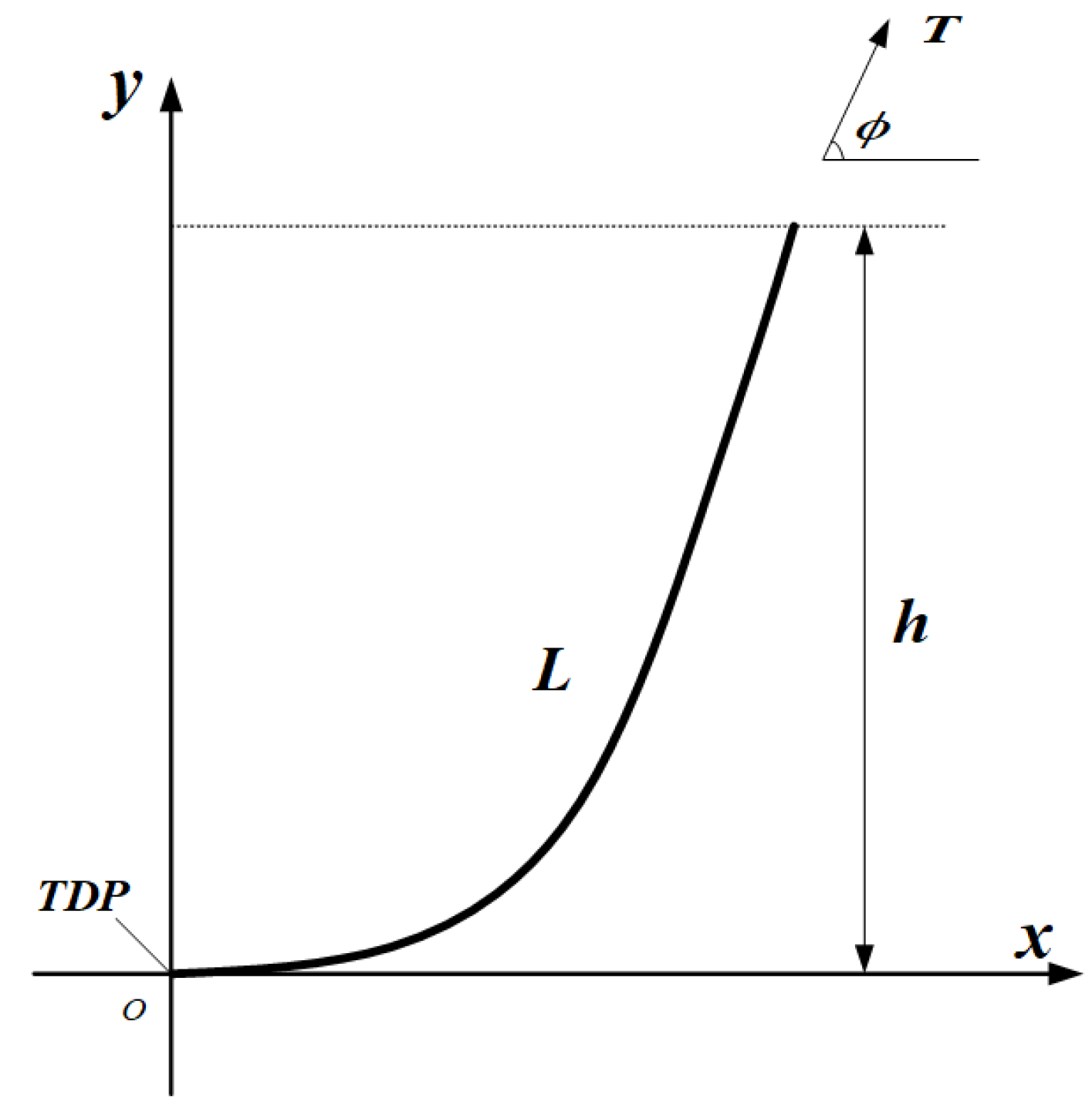
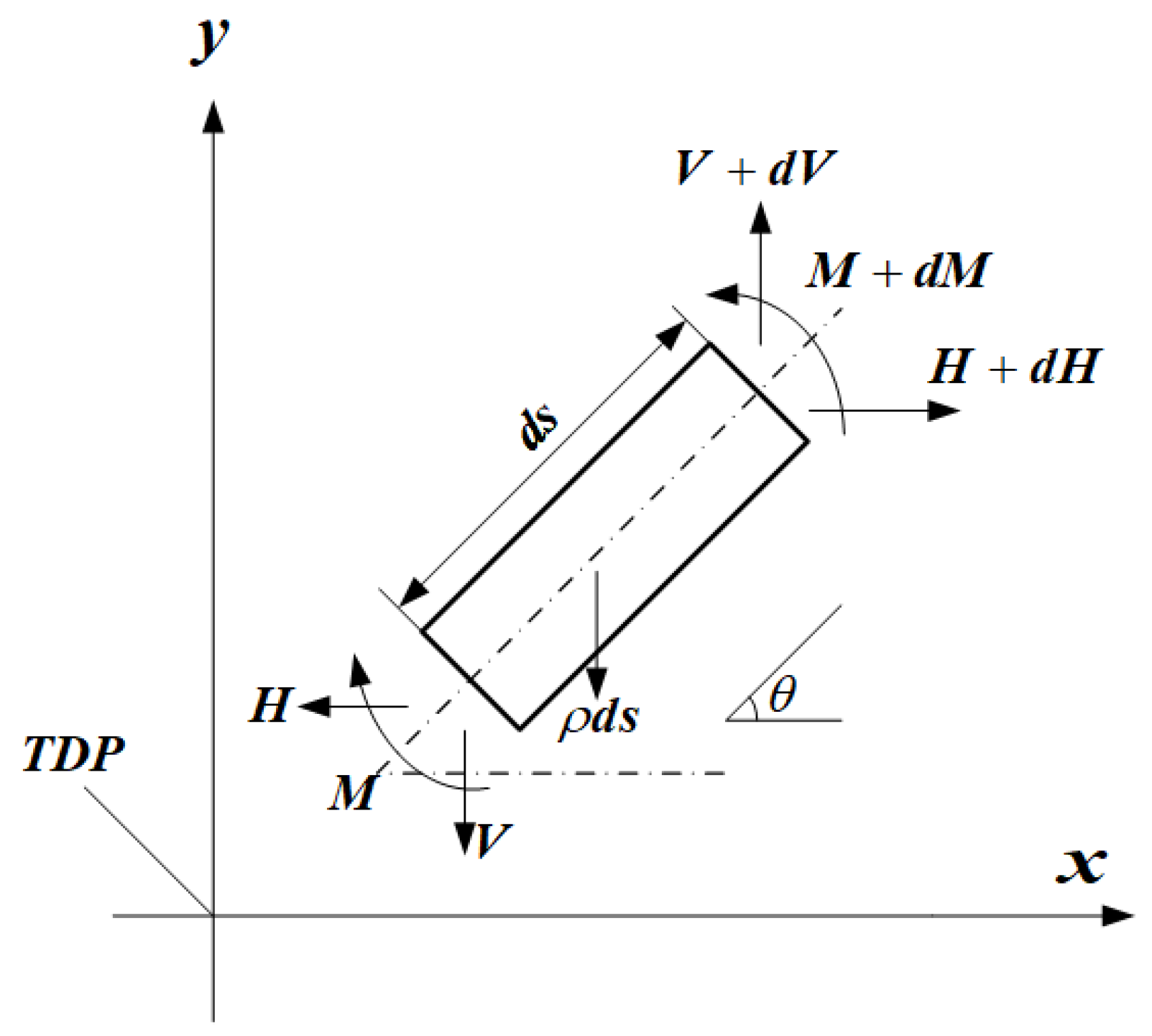
To analyze the stress state of a suspended pipeline, a coordinate system is established with the touchdown point (TDP) as the origin, as demonstrated in Figure 2. In this Figure 2, L represents the arc length of the pipeline, h signifies the water depth of installation, ϕ is the angle between the pipeline and the horizontal direction upon water entry, and T denotes the pipeline’s tension force. According to nonlinear beam theory [20], a force balance diagram for the pipeline’s micro-segment is established, as presented in Figure 3.
In this Figure 3, s denotes the unit arc length. ds indicates the pipeline’s micro-segment, θ is the angle between the pipeline’s micro-segment and the horizontal direction, V and H are the axial force components in the vertical and horizontal directions, respectively, and H is a function of x. M refers to the bending moment on the micro-segment, and ρ symbolizes the pipeline’s buoyant weight per unit length in water (the buoyancy in water minus the weight in air).
d M d s = H sin θ V cos θ
The balance equations for the pipeline’s micro-segment in the axial direction and the vertical direction are established:
d V d s = ρ
The pipe has a large bending deformation when laid; ignoring shear deformation, the pipe is considered as a beam and the bending moment of the pipe is obtained as:
M = E I d θ d s
Substituting Equations (2) and (3) into Equation (1) yields:
E I d 2 θ d s 2 + V cos θ H sin θ = 0
According to the Singular perturbation, introducing the dimensionless variable x = s / L ( x [ 0 , 1 ] ) , such that ε = E I H L 2 the equation is divided by H at both ends, gives:
ε d 2 θ d x 2 + V H cos θ sin θ = 0
At the TDP, s = 0 the shears force of the pipe:
Q = E I d 2 θ L 2 d x 2 = d M d s = H sin θ V cos θ
where x = 0 . The deformation of Equation (5) yields the vertical component of the force at s = 0 :
V = H tan θ ε cos θ d 2 θ d s 2
where x = 0 and s = 0 . Substituting a = tan θ ,   b = 1 cos θ d 2 θ d s 2 in Equation (7), we obtain:
V = H ( a + ε b )
Integrating Equation (2) and substituting ω = ρ L H , the expression for the vertical component of the force for s = 0 is given by:
V = H ( ω x + a + ε b )
Substituting Equation (9) into Equation (5) yields the control equation for CWP as:
ε d 2 θ d x 2 + ( ω x + a + ε b ) cos θ sin θ = 0 , 0 < ε < < 1
A nonlinear second-order differential equation characterizes the dynamic response control equation of this cold-water pipe, and the second-order derivative of the equation has a coefficient of small parameters.

2.2. Boundary Conditions

To solve the ordinary differential equations (ODE) that describe the pipeline shape, we need to specify two boundary conditions at the two ends of the pipeline. One end is connected to the system with bending stiffness (beam), and the other consists of hinges attached to the OTEC platform. Therefore, we assume that the bending moment at both ends is zero, i.e., M(s = 0) = 0 and M(s = 1000) = 0. This gives us a two-point boundary value problem that can be integrated numerically.
M ( s = 0 ) = 0 E I θ ( 0 ) = 0 θ ( 0 ) = 0 A B
M ( s = 1000 ) = 0 E I θ ( 1000 ) = 0 θ ( 1000 ) = 0
From Figure 4, the geometric relationship between CWP and the cable is expressed as
L r t o t = L P + L r f
v P = v r
where Equation (13) indicates that the horizontal distance Lrtot between the tug and the OTEC unit is equal to the sum of the horizontal projection Lr of the CWP and the horizontal projection Lrf of the cable. The following expressions apply:
L r t o t = 1000 m L r = 0 1000 cos θ ( s ) d s L r f = L r t o t L r f = a C a r sinh s r + s r f a C a r sinh s r f a C
where Lrtot denotes the horizontal distance between the tug and the OTEC unit, Lp the horizontal projection of the CWP, Lr the horizontal projection of the cable, s the arc length of the pipeline, θ the angle between the pipeline and the horizontal direction, rf the cable section suspension chain line scale factor, and ar the gravity per unit length of cable.
Equation (14) indicates that the vertical projection of CWP. v P is equal to the vertical point of the cable v r . The following expressions apply:
v p = 0 1000 sin θ ( s ) d s v r = v r t o t v r f = a C a r cosh L r + L r f a C 1 a r cosh L r f a C 1
The original problem has been transformed into a new problem where there are only four unknowns that need to be solved. This can simplify the problem and make it easier to solve, as shown in Table 2.

2.3. Singular Perturbation

2.3.1. General Solution for the Exterior

Singular perturbation [21] is a widespread analytical approximation method for dealing with nonlinear problems. It is based on small parameters and is well-suited for significant deformation problems in pipeline laying. In this paper, the matching asymptotic expansion idea of the singular perturbation method is combined with the van Dyke matching theory to solve the problem. The basic idea is to check the external solution of the boundary layer with the internal solution. The external solution is obtained directly by the regular perturbation method, which is only valid outside the boundary layer and falls within it. The internal resolution of the boundary layer cannot be obtained directly by the regular perturbation method but by scaling the magnitude of the independent variable. Then, the external and internal solutions are matched through matching conditions to determine the undetermined constants. Finally, the composite key is obtained from the exterior and interior solutions.
The outer or external field solution is one stream of the general solution in the exterior region. Based on the above analysis, it is known that the boundary points are x = 0 and x = 1 . For the external solutions, the regular regression method can be directly applied to expand them. Expanding the variables θ in the control equation into a power series of small parameters ε , it is obtained:
θ = i = 0 ε i / 2 θ i ( x ) = θ 0 + ε θ 1 + ε θ 2 + O ( ε 3 / 2 )
where O ( ε 3 / 2 ) is the higher-order correction term. Substituting Equation (17) into Equation (10), the 0th order approximation is obtained as:
θ 0 ( x ) = arctan ( ω x + a )
The first-order approximation is given by
θ 1 ( x ) = 0
The second-order recurrence results in the following:
ω x + a sin θ 0 + cos θ 0 θ 2 = θ 0 + b 0 cos θ 0
where, b = 1 cos θ d 2 θ d s 2 = i = 0 ε i / 2 b 0 , b 0 is the zero-order approximation of b.
Substitute the results of Equations (18) and (19) into Equation (14). The second-order approximation is obtained as:
θ 2 ( x ) = 2 ω x + a ω 2 1 + ω x + a 2 5 / 2 + b 0 1 + ω x + a 2
Up to this point, the external solution can be obtained as follows:
θ 0 = arctan ( ω x + a ) + 2 ω x + a ω 2 1 + ω x + a 2 5 / 2 + b 0 1 + ω x + a 2 ε + O ( ε 3 / 2 )
The solution near the boundary layer can be called the interior solution or the infield solution to describe the situation when the independent variables converge to the boundary. For the interstitial in this paper, the boundary layer is x = 0 and x = 1 .

2.3.2. Solution at the Boundary Layer

(1)
Internal solution around x = 0
The previous analysis of the matched asymptotic expansion method shows that the coordinate transformation must be performed first when solving the interior solution. Introducing a pair of coordinates ζ in the vicinity of the amplification x = 0 . Since the highest order in the equation is the second order, the transformation ζ = x ε can eliminate the higher order derivatives in the equation, and the substitution ε d 2 θ d x 2 = ε d 2 θ d ε ζ 2 = d 2 θ d ζ 2 into the control Equation (10) yields:
d 2 θ d ζ 2 + ω ε ζ + a + ε b cos θ sin θ = 0
Transformation θ is performed such that θ ( x , ε ) = ψ ( x , ε ) + θ ( x , ε ) x = 0 = ψ , ( x , ε ) + arctan a , Equation (23) is transformed into:
d 2 ψ d ζ 2 + ω ε ζ + a + ε b cos ( ψ + arctan a ) sin ( ψ + arctan a ) = 0
Substituting α = ( 1 + a 2 ) 1 / 4 , μ = θ ( x , ε ) x = 0 = arctan a in the simplification gives:
d 2 ψ d ζ 2 + ω ε ζ + a + ε b cos ( ψ + μ ) α 2 sin ψ = 0
The following is the same as the external solution. The power series of the expansion is obtained.
ψ = i = 0 ε i / 2 ψ i ( ζ )
The equation at the zero order can be found by finding the recurrence relation of each order according to the external solution.
ψ 0 α 2 sin ψ 0 = 0
The equation in the first order is:
ψ 0 + ω ζ cos ( ψ 0 + μ ) α 2 cos ψ 0 ψ 1 = 0
The equation in second order is:
ψ 2 + b cos ( ψ 0 + μ ) ζ sin ( ψ 0 + μ ) α 2 cos ψ 0 ψ 2 = 0
Equation (26) is solved in general as
ψ 0 = 0
And substituted into Equation (27) to obtain the general solution as
ψ 1 = A e a ζ + B e a ζ + ζ ω α 4
According to the boundary matching, we can get A = ω α 5  B = 0, then Equation (31) becomes:
ψ 1 = ω α 5 e a ζ + ζ ω α 4
Substituting Equations (30) and (31) into Equation (28) yields the general solution:
ψ 2 = C ( ζ 2 + ζ α + 1 α 2 ) e a ζ + D e a ζ b α 4 + a ω 2 ζ 2 α 8 ζ 2 + 2 a ω 2 α 10
According to the boundary condition and the matching condition of the binomial expansion, we get C = a ω 2 4 α 4 , D = 0 , Equation (32) becomes:
ψ 2 = a ω 2 4 α 8 ( ζ 2 + ζ α + 1 α 2 ) e a ζ b α 4 + a ω 2 ζ 2 α 8 ζ 2 + 2 a ω 2 α 10
bringing each general solution into the power series of:
ψ = ψ 0 + ε ψ 1 + ε ψ 2 + 0 ( ε 3 / 2 ) = ε ( ω α 5 e α ζ ζ ω α 4 ) + ε [ a ω 2 4 α 8 ( ζ 2 + ζ α + 1 α 2 ) e a ζ b α 4 + a ω 2 ζ 2 α 8 ζ 2 + 2 a ω 2 α 10 ] + O ( ε 3 / 2 )
Substituting θ ( x , ε ) = ψ ( x , ε ) + arctan a into Equation (35) gives the internal solution near x = 0 as:
θ 0 I = arctan a + ψ = arctan a + ψ 0 + ε ψ 1 + ε ψ 2 + 0 ( ε 3 / 2 ) = arctan a + ε ( ω α 5 e α ζ ζ ω α 4 ) + ε [ a ω 2 4 α 8 ( ζ 2 + ζ α + 1 α 2 ) e a ζ b α 4 + a ω 2 ζ 2 α 8 ζ 2 + 2 a ω 2 α 10 ] + O ( ε 3 / 2 )
(2)
Internal solution around x = 1
In the same way, as used at x = 0 , the independent variable is scaled up by introducing a change in coordinates ζ = 1 x ε , Let, θ ( x , ε ) = φ ( x , ε ) + θ ( x , ε ) x = 1 = φ ( x , ε ) + arctan ( ω + a ) , β = [ 1 + ( ω + a ) 2 ] 1 / 4 , follow the steps used at x = 0 to obtain the internal solution near x = 1 as:
θ 1 I = arctan ( ω + a ) ε [ 1 β ( λ + ω β 4 ) e β ξ + ξ ω β 4 ] + ε [ ω ( ω + a ) 4 β 4 ( λ + ω β 4 ) ( ξ 2 + ξ β + 1 β 2 ) e β ξ ω 2 ( ω + a ) β 8 ( ξ 2 + 2 β 2 ) + b 0 β 4 ] + O ( ε 3 / 2 )

2.3.3. Valid Solution across the Entire Domain

The unified expression for a valid solution over the entire domain is called a synthetic solution and is usually denoted by y C . There are two commonly used methods for synthesizing artificial solutions:
(1)
Additive synthesis method
y C = y O + y I ( y O ) I = y O + y I ( y I ) O
In Equation (32), ( y O ) I = lim x 0   y O the inner limit of the external solution ( y I ) O lim x 0   y I is called the outer limit of the internal solution.
(2)
Multiplicative synthesis
y C = y O y I ( y O ) I = y O y I ( y I ) O
The additive synthesis method applied in this paper yields an effective solution over the entire domain:
θ C = θ O + θ 0 I + θ 1 I ( θ O ) 0 I ( θ O ) 1 I
From Equation (22), replacing the external solution x = 0 with x for ζ ε yields the internal limit of the external solution as:
( θ O ) 0 I = arctan ( ω ζ ε + a ) + ε { 2 ( ω ζ ε + a ) ω 2 [ 1 + ( ω ζ ε + a ) 2 ] 5 / 2 + b 0 1 + ( ω ζ ε + a ) 2 } + O ( ε 3 / 2 )
From Equation (36), the external solution ζ is replaced by x ε at x = 0 to obtain the internal solution with the outer limit as:
( θ I ) 0 O = arctan a + ε ( ω α 5 e α x / ε x ω α 4 ε ) + ε [ a ω 2 4 α 8 ( x 2 ε + x α ε + 1 α 2 ) e α x / ε b 0 α 4 + a ω 2 x 2 α 8 ε + 2 a ω 2 a 10 ] + O ( ε 3 / 2 )
From Equation (22), substituting 1 ζ ε for x at x = 1 for the external solution yields the internal limit of the external solution as:
( θ O ) 1 I = arctan ( ω ω ξ ε + a ) + ε { 2 ( ω ω ξ [ 1 + ( ω ω ξ ε + a ) ω 2 ε + a ) 2 ] 5 / 2 2 + b 0 1 + ( ω ω ξ ε + a ) 2 } + O ( ε 3 / 2 )
The internal limit of the external solution is obtained by replacing ζ with 1 x ε at x = 1 by Equation (37):
θ 1 I = arctan ( ω + a ) ε [ 1 β ( λ + ω β 4 ) e β ( 1 x ) / ε + ω β 4 ω x ε ] + ε [ ω ( ω + a ) 4 β 4 ( λ + ω β 4 ) ( ( 1 x ) 2 ε + 1 x β ε + 1 β 2 ) e β ( 1 x ) / ε ω 2 ( ω + a ) β 8 ( ( 1 x ) 2 ε + 2 β 2 ) + b 0 β 4 ] + O ( ε 3 / 2 )
By substituting Equations (41) and (44), the synthetic solution is given as follows:
θ C = arctan ( ω x + a ) + ε { 2 ω 2 ( ω x + a ) [ 1 + ( ω x + a ) 2 ] 2 / 5 + b 0 1 + ( ω 1 x + a ) 2 } + ε ( ω α 5 e α x / ε x ω α 4 ε ) + ε ω α 5 e α x / ε ε a ω 2 4 α 8 ( x 2 ε + x α ε + 1 α 2 ) e α x / ε ε { ω ( ω + a ) 4 β 4 ( λ + ω β 4 ) [ ( 1 + x ) 2 ε + 1 x β ε + 1 β 2 ] } e β ( 1 x ) / ε
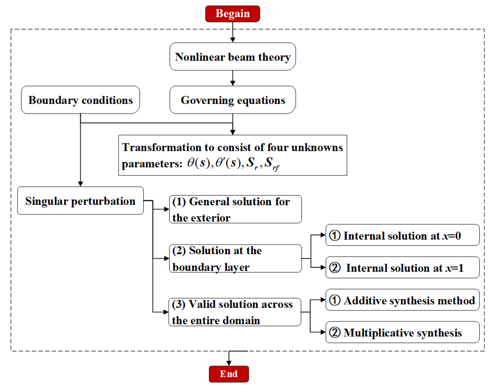
Equation (45) is the synthetic solution of the nonlinear differential equation for the CWP pipe, from which it can be seen that the internal solution decays exponentially with the increase of the internal solution ε . The internal solution a is valid only in the boundary layer, and its value tends to zero in the external region; outside the boundary layer, the morphology of the pipe is determined by the external solution, and the influencing factors of the external solution are the cable tension, the horizontal length of the suspended section of the pipe, the tensioning force, the wet weight of the pipe, and the water flow force. According to Equation (45), the morphology and bending moment of CWP pipe can be obtained by an iterative method. θ ( s ) and θ ( s ) are obtained by combining the ordinary differential Equation (10) and the boundary conditions (11) and (12) with the software “solve” in Matlab, and the nonlinear system of Equations (13) and (14) is formed by combining (13) and (14) and solving this type of singular-edge problems iteratively with the built-in Matlab function bvp4c. The results of bvp4c are imported into the fslove module to solve the associated solutions. As shown in Figure 5, a flowchart of the singular perturbation for cold-water pipes’ large deformation problem is given.

3. Solution Correctness and Validity

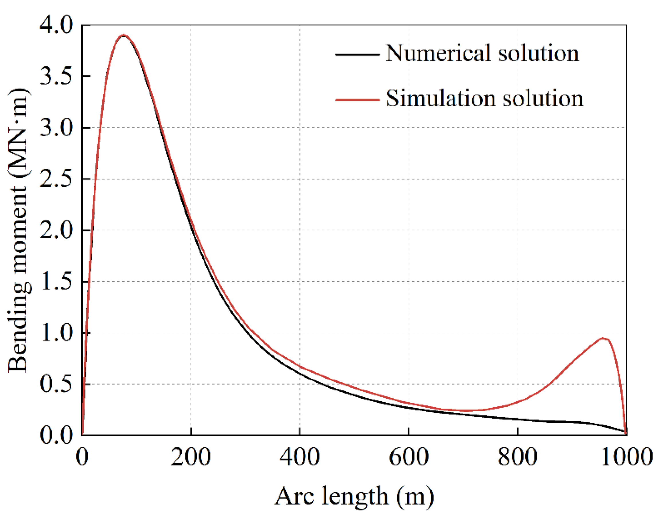
To validate the accuracy and efficacy of the singular perturbation method, we utilized the parameters for the cold-water pipe, environment, and fluid, as outlined in Table 3. Using OrcaFlex software, we conducted a finite element simulation of the bending moment exerted on the cold-water pipeline during installation, the results of which are juxtaposed against the method proposed in this paper, as depicted in Figure 6. One can discern that the numerical and simulated outcomes are nearly harmonious, with both revealing that the maximum bending moment occurs at a location 50~100 m away from the bottom of the pipe, boasting a value of 3.92 MN∙m. Notably, at a position approximately 100 m from the bottom of the pipe, the simulation results display numerical fluctuations, reaching minor peak values. This occurs as some buckling transpires at the point of articulation between the top tensioner and the CWP as the pipe begins to descend.

4. Results and Discussion

Drawing on the semi-analytical solutions articulated in this paper, it becomes evident that laying depth significantly impacts pipeline form, such as pipeline arc length substantially influencing the pipeline’s tension, curvature, bending moment, and stress. This section delves into the specific effects of these parameters on the mechanical properties of cold-water pipes, utilizing parameters as outlined in Table 3 for our analyses.

4.1. Influence of Laying Depth on Pipeline Form

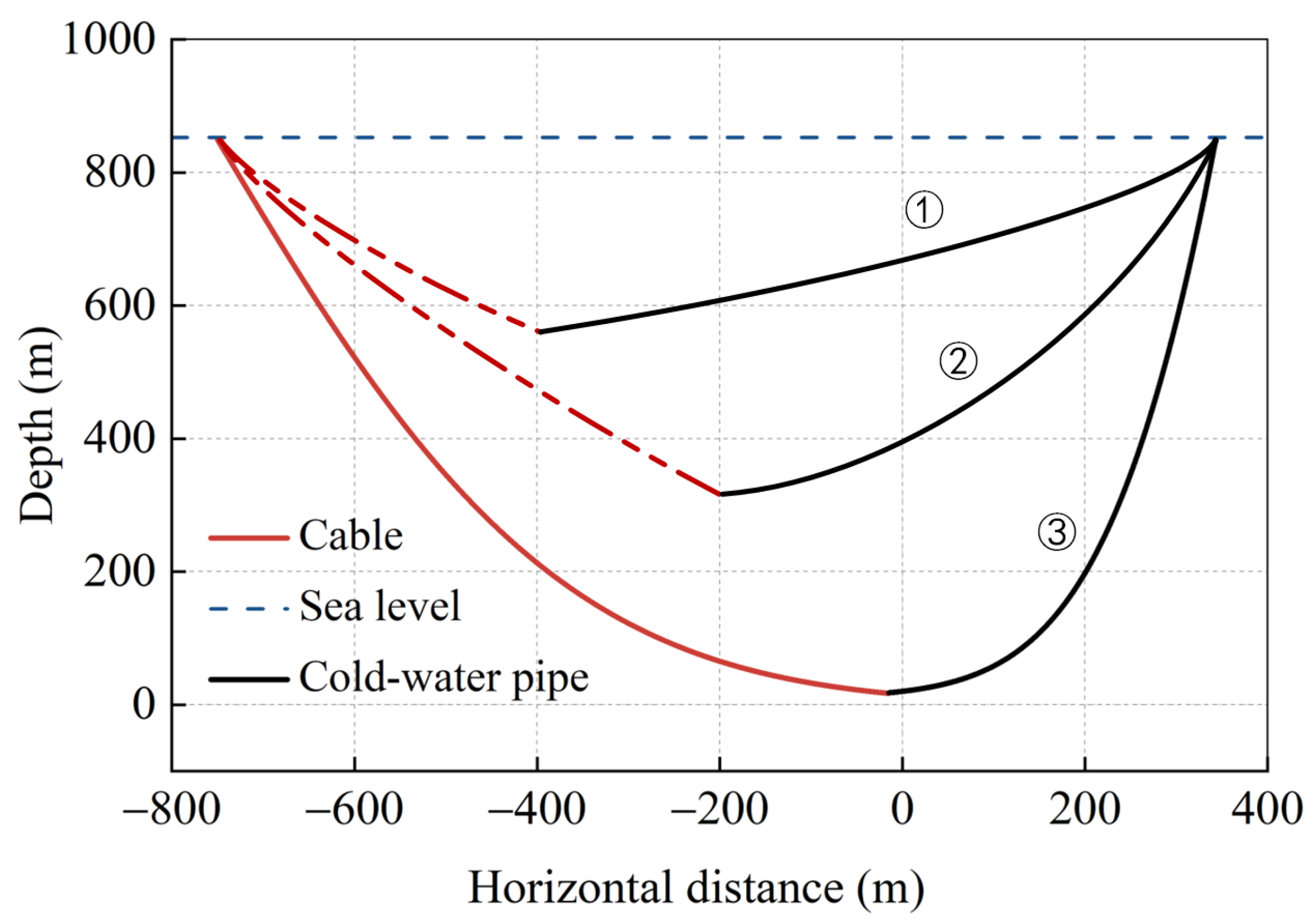
Figure 7 depicts the developmental curves of pipeline forms under different laying depths, where the water depth on the y-axis signifies the final form of the pipeline’s depth from the sea surface. It is perceptible that laying depth substantially impacts the final form of the pipeline. At a laying depth of 580 m, the pipeline is under gentle tension; as Curve 1 indicates, the pipe primarily withstands tension from the pipe-laying ship. As laying depth increases, at 320 m, the pipeline form gradually bends (Curve 2), reaching its ultimate state when the maximum bend occurs during the pipe-laying process (Curve 3). These findings affirm that significant arcs occur near the bottom of the pipe, validating the issue of high deflections during cold-water pipe (CWP) laying.

4.2. Parameter Analysis

4.2.1. Effect of Pipe Arc Length Tension

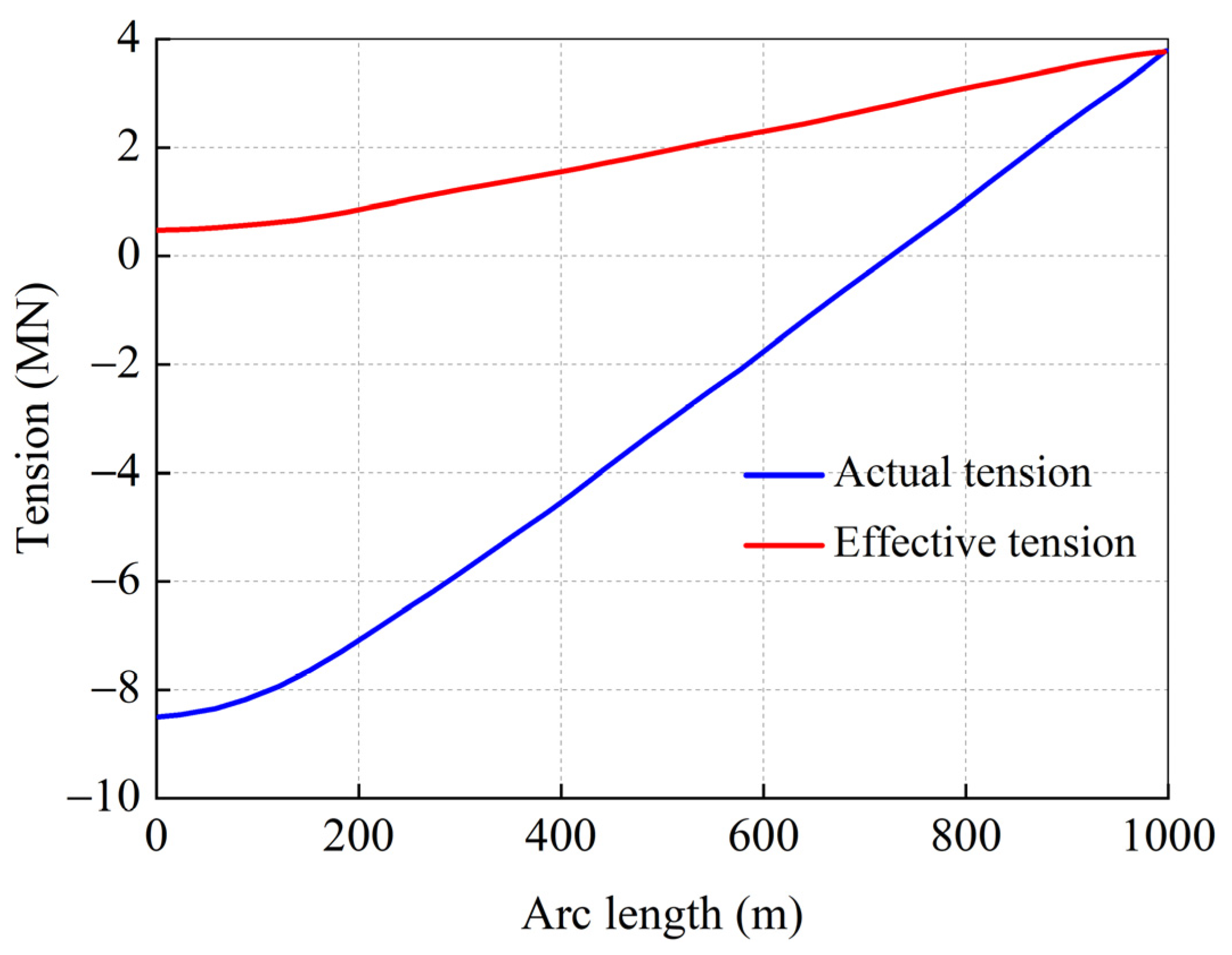
This section examines the influence of arc length on pipeline tension, choosing a pipeline length of 1000 m, with remaining parameters selected from Table 3, and employing Matlab’s fslove to collect values at 20 m intervals. Figure 8 delineates the developmental trend curves of pipeline tension under varying pipeline arc lengths. Figure 8 presents a graph tracing the evolution of actual and adequate tension in correlation to the pipeline’s arc length. The pipeline’s arc length significantly influences natural and compelling tension. The proper tension progressively escalates with an increase in the pipeline’s arc length.
In contrast, the actual tension initially declines to zero, then reverses its trend, matching the adequate tension at the pipeline’s maximum arc length. The effects of the pipeline’s arc length on actual and effective tension can be explained by bending forces. When the pipeline is turned to a specific arc, it endures bending forces perpendicular to its axial direction and is aimed at the centre of the bend. The bending force’s impact gradually intensifies as the pipeline’s arc length extends, resulting from an increase in the distance between the bending force and the center of the bend. However, this increases the magnitude of the bending force, counteracting the effect of actual tension, leading to a gradual reduction in the actual tension. As the pipeline’s arc length increases, the tension dominates, equating to the bending force at a certain point. Beyond this point, with the continuation of the arc length’s increase, the tension continues to grow until it equates to adequate tension.

4.2.2. Effect of Pipe Arc Length on the Curvature

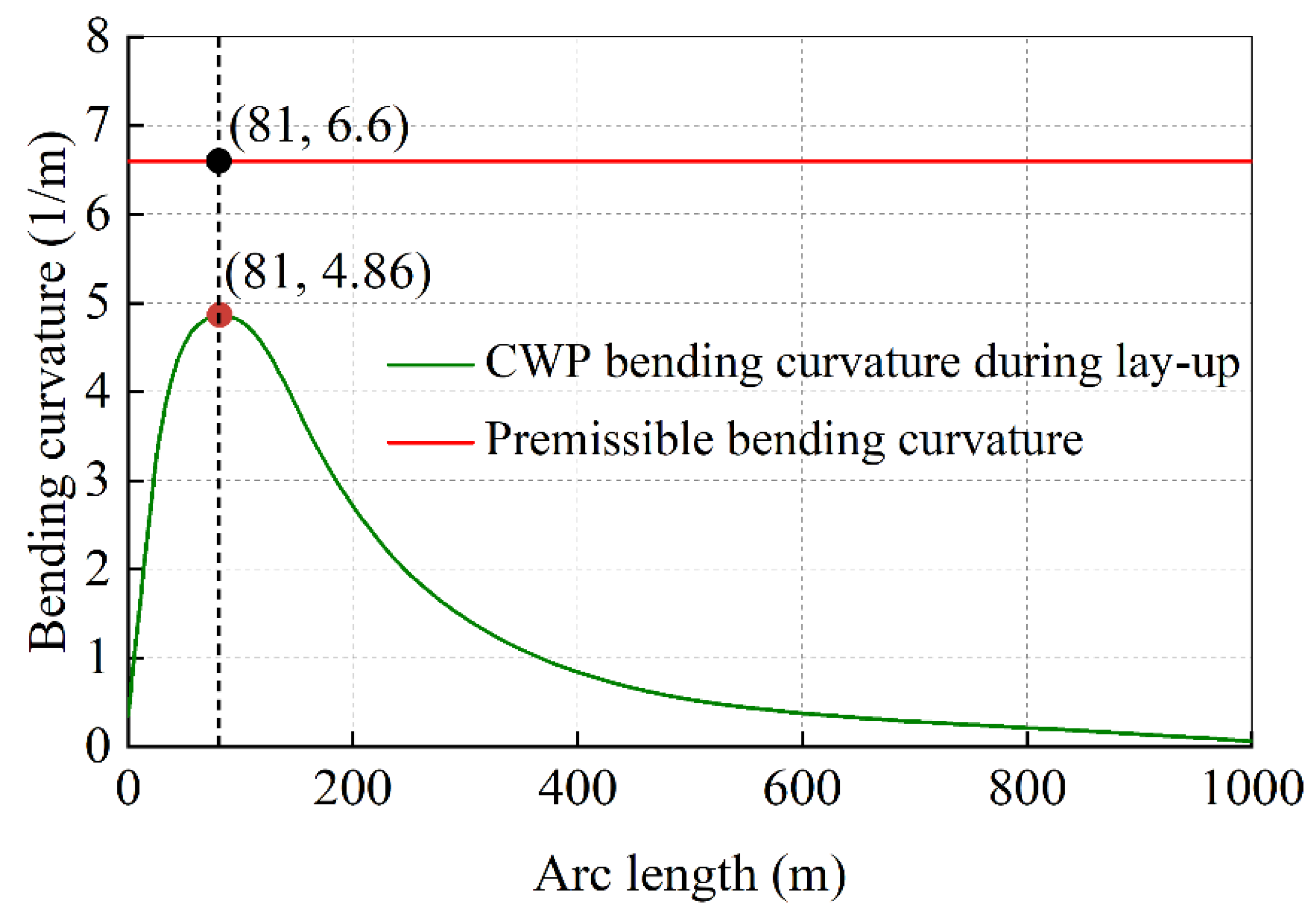
This section investigates the influence of pipeline arc length on pipeline curvature. With Matlab parameters selected and value intervals identical to the previous quarter, Figure 9 shows the developmental pattern of pipeline curvature under different arc lengths. With the increase in pipeline arc length, the pipeline’s bending curvature first increases, reaching its peak of 4.86 m at an arc length of 81 m, then gradually reducing to zero at the pipeline’s maximum arc length. The primary reason lies in the inverse relationship between the pipeline’s bending curvature and the bending angle. An increase in arc length implies a smaller bending angle, increasing the pipeline’s curvature. As the pipeline’s arc length continues to grow, the pipeline’s bending curvature begins to reduce. This is because of the existence of a bending moment during the bending process of the pipeline. This force can return the pipeline to a straight state. When the arc length increases to a certain extent, the effect of the bending moment surpasses that of the bending force, causing the pipeline’s bending curvature to start reducing. It is noteworthy that both actual and practical tension maxima appear near the hinge point at the pipeline’s top. Throughout the installation and laying process, the bending curvature of the pipeline’s arc length remains within the permissible bending curvature, indicating the feasibility of this installation and laying method.

4.2.3. Effect of Pipe Arc Length on Stress

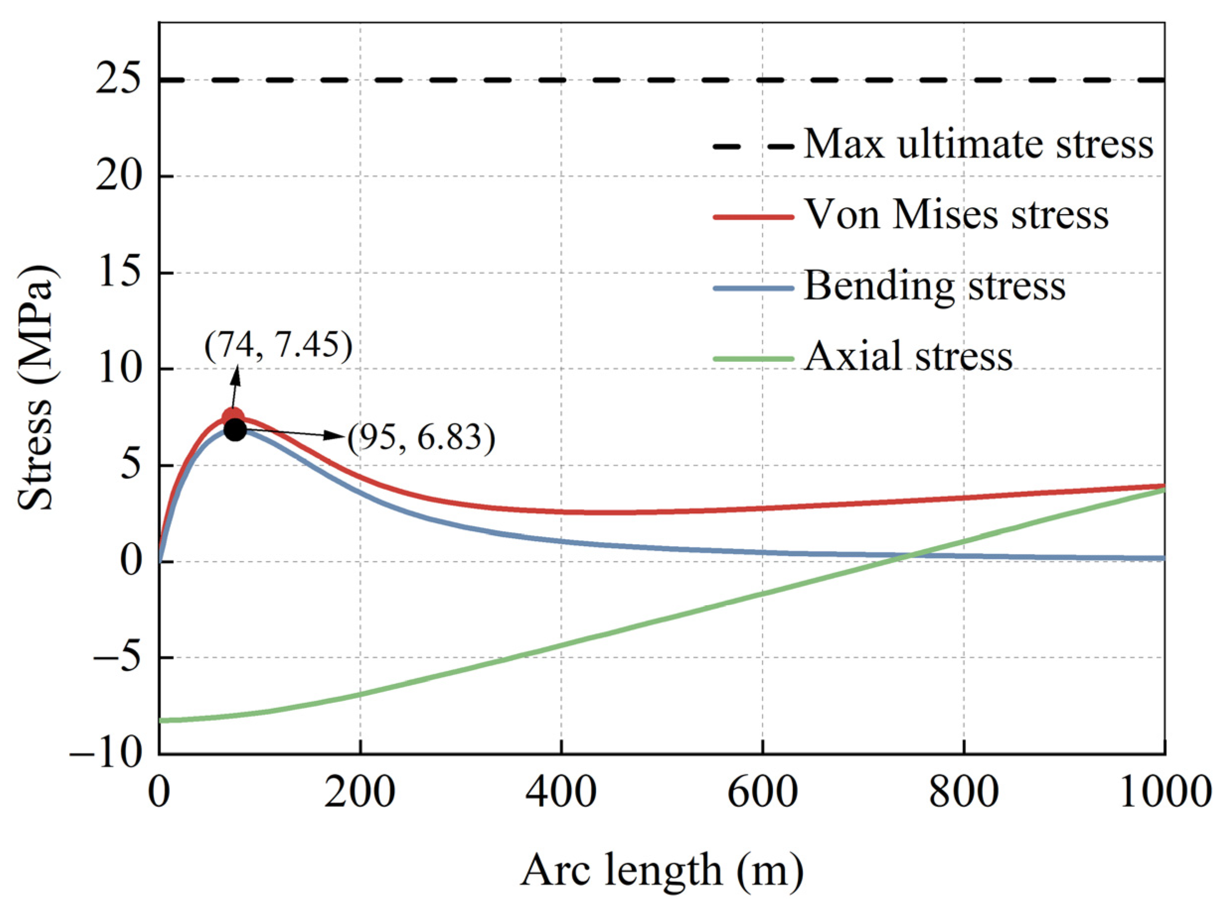
This section examines the effect of pipeline arc length on the pipeline’s Von Mises stress, bending stress, and axial stress. As shown in Figure 10, with the pipe arc length increasing, the pipe bends more and more, which means that the bending moment and the bending stress also increase. However, at some point, the bending moment reaches a maximum value and decreases as the pipe approaches a vertical position. This causes the bending stress to also fall after getting a peak value of 7.45 Mpa and 6.83 Mpa, respectively. The axial force and the axial stress are influenced by both the ship’s tension force and the pipe curvature’s bending force. As the pipe arc length increases, the tension force decreases due to the increased horizontal distance between the ship and the pipe. This causes the axial stress also to decrease. However, as the pipe bends more and more, the bending force increases and acts in the opposite direction of the tension force. This causes the axial stress to change its sign and start to increase in magnitude. The Von Mises stress is affected by both the bending stress and the axial stress. As both of them increase initially, so does the Von Mises stress. However, as both of them decrease after reaching their peak values, so does the Von Mises stress. Interestingly, at the pipeline’s maximum arc length, the pipeline’s bending stress reduces to zero, while Von Mises stress remains non-zero, corresponding to the actual installation and laying situations. Conversely, the pipeline’s axial stress gradually decreases to zero and then starts to increase in the opposite direction. At the pipeline’s maximum arc length, the pipeline’s axial stress equates to the Von Mises stress. Moreover, throughout the entire installation and laying process, the various stresses of the pipeline’s arc length.

5. Conclusions

This study has addressed the dynamic characteristics of large-diameter cold water pipes during the float-and-sink installation process, which is crucial for harnessing the potential of ocean thermal energy conversion. Based on nonlinear beam theory and the singular perturbation method, we have derived the theoretical model of the cold-water pipe’s mechanics and analyzed the pipeline shape, tension, bending curvature, and stress parameters of the cold-water pipe under different laying depths and arc lengths. The main conclusions are as follows:
(1)
A novel semi-analytical solution had been developed for the nonlinear differential Equation of the cold-water pipe, which can accurately and efficiently capture the pipeline form and stress state during the installation process. The solution has been validated by comparing it with numerical simulations using OrcaFlex software, showing good agreement and reasonable differences.
(2)
The laying depth significantly impacts the final form of the pipeline, which transitions from gentle to increasingly bent, exhibiting significant bending near the bottom of the pipeline. This confirms the likelihood of substantial deformation of large-diameter cold water pipes during the installation process and suggests the need for careful monitoring and control of the laying depth.
(3)
The pipeline’s arc length substantially influences the pipeline’s tension, curvature, bending moment, and stress. We have found that the bending curvature, Von Mises stress, and bending stress of the pipeline all first increase and then decrease as the arc length of the pipeline increases, peaking at about 80 m along the pipeline. We have also found that both actual and axial tension decrease and then increase with the increase in the pipeline arc length. These findings indicate that special attention should be given to the section of the pipeline at 50~100 m during the actual installation process to ensure the safe and smooth installation of the pipeline.
(4)
This study has some limitations that should be acknowledged and addressed in future research. First, we have assumed that the cold-water pipe is a uniform beam with constant cross-section and material properties, which may not be realistic for practical applications. Second, we have neglected some external load conditions such as wave-induced forces, soil-pipe interaction, and thermal effects, which may have significant effects on the dynamic behavior of the cold-water pipe. Third, we have only considered one installation method (the float-and-sink method), which may not be suitable for all scenarios and environments. Future research should aim to relax these assumptions and incorporate more realistic factors into the theoretical model, as well as explore other installation methods such as J-lay or S-lay.
(5)
The findings of this study provide valuable insights for practical cold-water pipe installation and laying, as well as for theoretical analysis and numerical simulation of large-diameter marine risers. The proposed semi-analytical solution can serve as a useful tool for designing and optimizing cold-water pipe systems for ocean thermal energy conversion projects. The results can also help to identify the critical parameters and regions that affect the mechanical performance of cold-water pipes and to develop effective strategies for mitigating potential risks and challenges during installation and operation.

Author Contributions

Conceptualization, D.W. and M.D.; methodology, D.W. and M.Z.; software, Z.M., J.T. and Y.Z.; validation, D.S., Z.M. and J.T.; formal analysis, D.W.; investigation, L.Z. and D.W.; resources, D.W.; data curation, D.W., Z.M. and J.T.; writing—original draft preparation, D.W.; writing—review and editing, D.W. and M.D.; visualization, D.W. and M.D.; supervision, D.W.; project administration, M.D.; funding acquisition, M.D., L.Z. and Y.Z. All authors have read and agreed to the published version of the manuscript.

Funding

Southern Marine Science and Engineering Guangdong Laboratory (Zhanjiang) (Grant No. ZJW-2019-05), and the National Natural Science Foundation of China (Grant No. 52201347).

Institutional Review Board Statement

The study did not require ethical approval.

Informed Consent Statement

Informed consent was obtained from all subjects involved in the study.

Data Availability Statement

Data sharing is not applicable to this article.

Acknowledgments

The authors gratefully acknowledge the financial support provided by the Found of Southern Marine Science and Engineering Guangdong Laboratory (Zhanjiang) (Grant No. ZJW-2019-05), and the National Natural Science Foundation of China (Grant No. 52201347). All the authors express heartfelt appreciation to editors and reviewers for their valuable comments and suggestions.

Conflicts of Interest

The authors declare no conflict of interest.

References

  1. Adiputra, R.; Utsunomiya, T. Stability based approach to design cold-water pipe (CWP) for ocean thermal energy conversion (OTEC). Appl. Ocean Res. 2019, 92, 101921. [Google Scholar] [CrossRef]
  2. Li, Z.; Wang, C.; He, N.; Zhao, D.Y. An Overview of Deepwater Pipeline Laying Technology. China Ocean Eng. 2008, 22, 521–532. [Google Scholar]
  3. Zan, Y.; Yuan, L.; Huang, K.; Ding, S.; Wu, Z. Numerical Simulations of Dynamic Pipeline-Vessel Response on a Deepwater S-Laying Vessel. Processes 2018, 6, 261. [Google Scholar] [CrossRef]
  4. Keesmaat, K. Installation Limits of Large Diameter Cold Water Pipes in Deep Water for Land-Based OTEC Plants; TU Delft: Delft, The Netherlands, 2015. [Google Scholar]
  5. Miroslav, S. (Pipe-Life) Email Conversation with Pipe-Life; Large Diameter OTEC Pipe Installation Thesis Bluerise. 2015. [Google Scholar]
  6. Senthil, B.; Selvam, R.P. Dynamic Analysis of a J-lay Pipeline. Procedia Eng. 2015, 116, 730–737. [Google Scholar] [CrossRef]
  7. Konuk, I. Higher Order Approximations in Stress Analysis of Submarine Pipelines. J. Energy Resour. Technol. 1980, 102, 190–196. [Google Scholar] [CrossRef]
  8. Lenci, S.; Callegari, M. Simple analytical models for the J-lay problem. Acta Mechanica 2005, 178, 23–39. [Google Scholar] [CrossRef]
  9. Brown, R.J.; Palmer, A. Developing Innovative Deep Water Pipeline Construction Techniques with Physical Models. J. Offshore Mech. Arct. Eng. 2004, 129, 56–60. [Google Scholar] [CrossRef]
  10. Gong, S.; Chen, K.; Chen, Y.; Jin, W.; Li, Z.; Zhao, D. Configuration analysis of deepwater S-lay pipeline. China Ocean Eng. 2011, 25, 519–530. [Google Scholar] [CrossRef]
  11. Winget, J.M.; Huston, R.L. Cable dynamics—A finite segment approach. Comput. Struct. 1976, 6, 475–480. [Google Scholar]
  12. Santillan, S.T.; Virgin, L.N. Numerical and experimental analysis of the static behavior of highly deformed risers. Ocean Eng. 2011, 38, 1397–1402. [Google Scholar] [CrossRef]
  13. Wang, L.; Ju, M.; Xing, X.; Yun, F.; Wang, X. Dynamic Behavior of the Deepwater Flexible Pipeline during Pipe Laying Process. J. Mar. Sci. Eng. 2020, 8, 286. [Google Scholar] [CrossRef]
  14. Xu, P.; Du, Z.; Gong, S. Numerical Investigation into Freak Wave Effects on Deepwater Pipeline Installation. J. Mar. Sci. Eng. 2020, 8, 119. [Google Scholar] [CrossRef]
  15. Ghafouri, M.; Ghassabi, M.; Zarastvand, M.R.; Talebitooti, R. Sound propagation of three-dimensional sandwich panels: Influence of three-dimensional re-entrant auxetic core. AIAA J. 2022, 60, 6374–6384. [Google Scholar] [CrossRef]
  16. Zarastvand, M.R.; Asadijafari, M.H.; Talebitooti, R. Acoustic wave transmission characteristics of stiffened composite shell systems with double curvature. Compos. Struct. 2022, 292, 115688. [Google Scholar] [CrossRef]
  17. Alanazi, M.J.; Qinghua, Y.; Al-Bukhaiti, K. Performance Study of Buried Pipelines under Static Loads. Civ. Eng. J. 2022, 8, 1–23. [Google Scholar] [CrossRef]
  18. Yamini, O.A.; Movahedi, A.; Mousavi, S.H.; Kavianpour, M.R.; Kyriakopoulos, G.L. Hydraulic Performance of Seawater Intake System Using CFD Modeling. J. Mar. Sci. Eng. 2022, 10, 988. [Google Scholar] [CrossRef]
  19. Nogmov, M.K.; Lianov, I.M.; Lysenko, V.R.; Dmitrichenko, N.V. Development of a Flow-Measuring Hydropneumatic Bench for Testing Pipeline Valves. Civ. Eng. J. 2023, 9, 166–182. [Google Scholar] [CrossRef]
  20. Fraenkel, L.E. Perturbation Methods; Academic Press: Cambridge, MA, USA, 1980. [Google Scholar]
  21. Lange, C.G.; Miura, R.M. Singular perturbation analysis of boundary value problems for differential-difference equations. V. Small shifts with layer behavior. SIAM J. Appl. Math. 1994, 54, 249–272. [Google Scholar] [CrossRef]
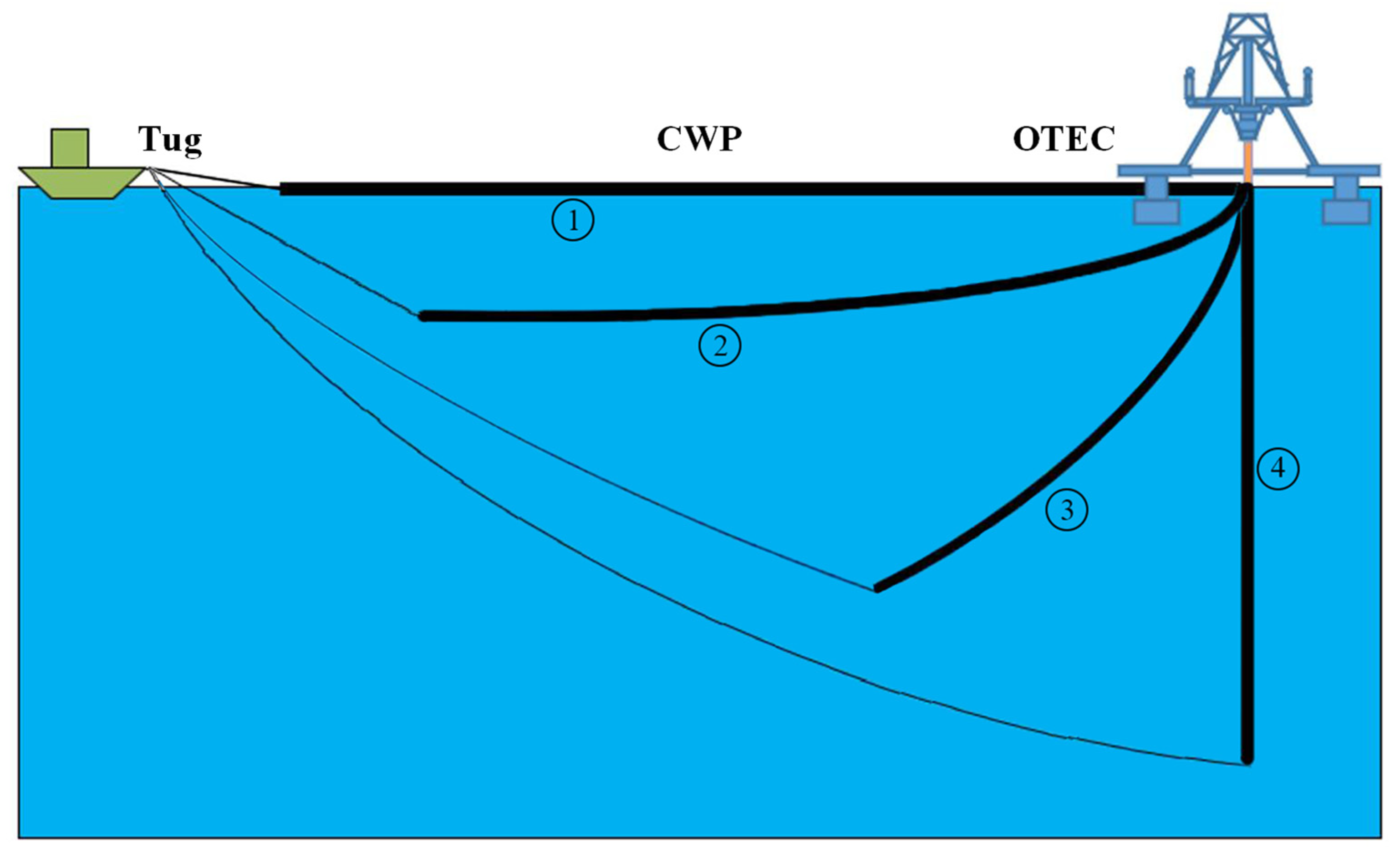
Figure 1. Floating sink method working principle.
Jmse 11 01520 g001
Figure 2. Pipeline stress model.
Jmse 11 01520 g002
Figure 3. Pipeline micro-section force balance diagram.
Jmse 11 01520 g003
Figure 4. Laying Process Pipeline Relations.
Jmse 11 01520 g004
Figure 5. Flowchart of cold-water pipe large deformation problems.
Jmse 11 01520 g005
Figure 6. Comparative analysis of CWP bending moment.
Jmse 11 01520 g006
Figure 7. Pipe shape and laying depth.
Jmse 11 01520 g007
Figure 8. Pipe shape and depth.
Jmse 11 01520 g008
Figure 9. Bending Curvature and Pipe Arc Length.
Jmse 11 01520 g009
Figure 10. Stress and Pipe Arc Length.
Jmse 11 01520 g010
Table 1. Nomenclature.
ParametersDescription
LPipe length
EIPipe bending stiffness
QcwPipeline cold seawater flow rate
LTOPThe horizontal distance between tug and OTEC
HLaying water depth
SrCable arc length
θ ( s ) The angle between CWP and the horizontal plane
θ ( s ) The curvature of the bend along the CWP pipeline
SurfCable extension arc length
v Cold seawater flow rate
acCable section suspension chain line scale factor
μ C Gravity per unit length of cable
TThe tensioning force of the pipe
LPThe horizontal projection of CWP
LrHorizontal projection of the cable
VrVertical projection of the cable
VpVertical projection of CWP
DSEquivalent single-layer pipe outer diameter
Table 2. Unknown variable.
UnknownDescription
θ ( s ) Angle between CWP and horizontal plane
θ ( s ) Bending curvature along the CWP line
S r Cable arc length
S r f Cable extension arc length
Table 3. CWP, environment and other parameters.
ParameterValues
Pipe length (m)1000
Pipe outside diameter (m)1.564
Pipe inner diameter (m)1.5
Unit length dry weight (kg/m)235
Pipe density (kg/m3)960
Modulus of elasticity (Gpa)0.9
Wave height (m)4.8
Wave phase angle (o)180
Water depth (m)1200
Seawater density (kg/m3)1025
Wave period (s)7.8
Sea surface current velocity (m/s)0.99
Sea current subsea current velocity (m/s)0
Ship—platform maximum distance (m)2250
Ship movement speed (m/s)3.5
Cable length (m)1250
Disclaimer/Publisher’s Note: The statements, opinions and data contained in all publications are solely those of the individual author(s) and contributor(s) and not of MDPI and/or the editor(s). MDPI and/or the editor(s) disclaim responsibility for any injury to people or property resulting from any ideas, methods, instructions or products referred to in the content.