1. Introduction
The environmental pollution caused by the burning of traditional fossil fuels for energy has become the main bottleneck restricting the development of the world economy [
1,
2,
3,
4]. The use of renewable energy sources such as offshore wind and offshore solar energy provides an effective way to solve the above problem [
5,
6]. Offshore wind and offshore solar energy save land area and make full use of marine resources. However, large-scale intermittent renewable energy has brought new challenges to the stable operation of DC microgrids [
7,
8]. As an important component of DC microgrids, energy storage systems (ESSs) provide stable power support for the DC bus and solve the problem of the unstable output power of renewable energy [
9]. Renewable energy and energy storage units (ESUs) connected to DC microgrid systems can avoid energy waste. In recent years, with the development of renewable energy technology, an offshore isolated island DC microgrid system has attracted the attention of scholars. The system can solve the power supply problem of isolated islands far away from land. However, a large number of renewable energy sources and ESUs with power electronic converters connected to an offshore isolated island DC microgrid system can decrease the system’s inertia [
10]. Methods such as virtual inertia adaptive control [
11], virtual DC machine (VDCM) control [
12], and emulated inertia control [
13] are proposed by researchers to improve the stability of low-inertia DC microgrid systems.
In order to improve the service life of ESUs to prevent the phenomenon of overcharge or over-discharge, state of charge (SOC) balance control in ESSs has attracted the interest of a wide range of scholars [
14]. For SOC balance control, a large number of research results have been obtained [
15,
16,
17,
18,
19,
20,
21,
22,
23,
24]. These control methods can be divided into three main categories: droop control, hierarchical control, and consensus control. Droop control is widely used in SOC balance control due to its simple control principle. However, the droop effect will cause a deviation between the actual bus voltage and the bus voltage normal value [
15,
16,
17]. In order to overcome the shortcomings of bus voltage deviation in [
15,
16,
17], hierarchical control is proposed in [
18,
19,
20]. For hierarchical control, the droop control is used in the primary layer to properly distribute power reasonably so that the SOCs eventually reach consistency. The second layer control uses PI control, consensus control, or other controls to compensate for the bus voltage deviation caused by the primary layer control, and the second layer control can maintain the bus voltage at the normal value. In [
21,
22,
23], consensus control is directly used for SOC balancing. The SOCs can eventually achieve consistency under the action of consensus control. The above methods do not take into account the system inertia enhancement; therefore, these controls have limited effect on improving the transient behavior of the DC microgrid. In particular, an SOC-based virtual DC machine control is proposed in [
24]. In the case of SOC balance, the VDCM control can keep the bus voltage at a normal value without additional secondary voltage restoration control. In addition, the VDCM control introduces an inertial link and a damping link, which are beneficial to improving the dynamic characteristics of the DC microgrid system. Therefore, introducing VDCM control into SOC balancing can not only achieve the consistency of SOCs, but also overcome the disadvantage of low inertia in the DC microgrid.
Inspired by the idea of AC virtual synchronous machine (VSM) control, VDCM control is proposed. VDCM control is quite different from AC VSM control. In AC VSM control, its speed corresponds to the grid frequency, while in VDCM control, its speed has no direct relationship with the grid frequency. Therefore, it is necessary to conduct further research on the analysis and improvement of VDCM. For VDCM control, the inertia characteristics are mainly determined by the inertia time constant
J. The ideal state is that when the DC microgrid system is disturbed, it is hoped that VDCM control can alleviate the impact of disturbance by injecting virtual inertia into the DC microgrid system. In addition, as for inertia time constant
J and damping constant
D, the influence of
J and
D on the dynamic characteristics of the system is discussed in [
25,
26,
27]. The results show that
J and
D with self-adaptive adjustment have a better effect in suppressing frequency fluctuation and voltage fluctuation than constant
J and
D. The above experimental results are based on a virtual synchronous generator. However, there is also the problem of voltage fluctuation in the DC microgrid. For VDCM control, there are few achievements in using adaptive
J and
D to suppress voltage fluctuation. Therefore, it is necessary to study VDCM with adaptive
J and
D to improve bus voltage dynamic characteristics.
In addition to the above-mentioned problems in VDCM control, there is another crucial problem that is unique to VDCM control applied for SOC balancing. The unique issue is the design of virtual armature resistance since virtual armature resistance determines the SOC balance time. The virtual armature resistance in VDCM is actually the same principle as the droop coefficient in droop control [
24]. Therefore, the droop coefficient in the existing literature can be directly used in VDCM control for SOC balancing. At present, the droop coefficient design is mainly divided into three categories: the constant droop coefficient [
18,
19,
20], fuzzy logic [
16,
17], and the droop coefficient of SOC-related functions [
15,
28,
29]. At the beginning of SOC balance control, the droop coefficient is chosen as a constant. And if this constant is too large, the bus voltage deviation will be larger, but the SOC balancing time will be shorter; if the constant is too small, the SOC balance time will be longer, but the bus voltage deviation will be smaller. In order to balance the relationship between bus voltage deviation and SOC balance time, some scholars apply fuzzy logic to the design of the droop coefficient. However, the above methods ignore the influence of SOCs with different ESUs on SOC balance control. Therefore, in [
15] and [
28,
29], the droop coefficients are designed as SOC-related functions. With this design, the droop coefficient has a strong adaptive ability.
To summarize the above discussions, an improved SOC-based bidirectional virtual DC machine control for energy storage systems in offshore isolated island DC microgrids is proposed in this paper. The contributions of the proposed control are as follows: firstly, compared with the traditional VDCM control in [
24], the improved VDCM control removes the power loop and torque loop in SOC balancing. Secondly, aimed at the problem of the traditional VDCM being unable to adaptively suppress the bus voltage when disturbances occur, the
J and
D of the improved VDCM control can adaptively adjust according to the bus voltage difference and the bus voltage difference change rate. Therefore, the proposed control can adaptively suppress the bus change to obtain better dynamic performance. Thirdly, aimed at the problem of SOC balance time, an improved SOC-based VDCM virtual armature resistance is proposed to reduce the SOC balance time.
The rest of this paper is organized as follows.
Section 2 reviews the traditional VDCM control, and on this basis, an improved VDCM control, without a power loop and torque loop, and with adaptive
J and
D, is proposed in this paper.
Section 3 describes the improved SOC-based bidirectional virtual DC machine control and introduces the SOC-based virtual armature resistance to realize the fast balancing of SOCs. In
Section 4, the small signal models of EUS converters and DC microgrids are established in this section, and the stability of the system is analyzed.
Section 5 gives experimental simulation cases and comparative simulation cases to verify and compare the theoretical conclusions. The conclusions are presented in
Section 6.
2. An Improved Bidirectional VDCM Control with the ESU
The lack of an inertia characteristic of a power electronic converter makes the DC bus voltage change rapidly when disturbances occur, which eventually leads to power quality degradation [
10]. However, DC machines can provide inertia and damping characteristics for power systems [
30]. The mechanical equation and electromotive force (EMF) balance equation of DC machines are applied to DC converters control, so that DC converters’ port exhibits inertia and damping characteristics of DC machine [
31]. The technology is called the virtual DC machine [
32,
33].
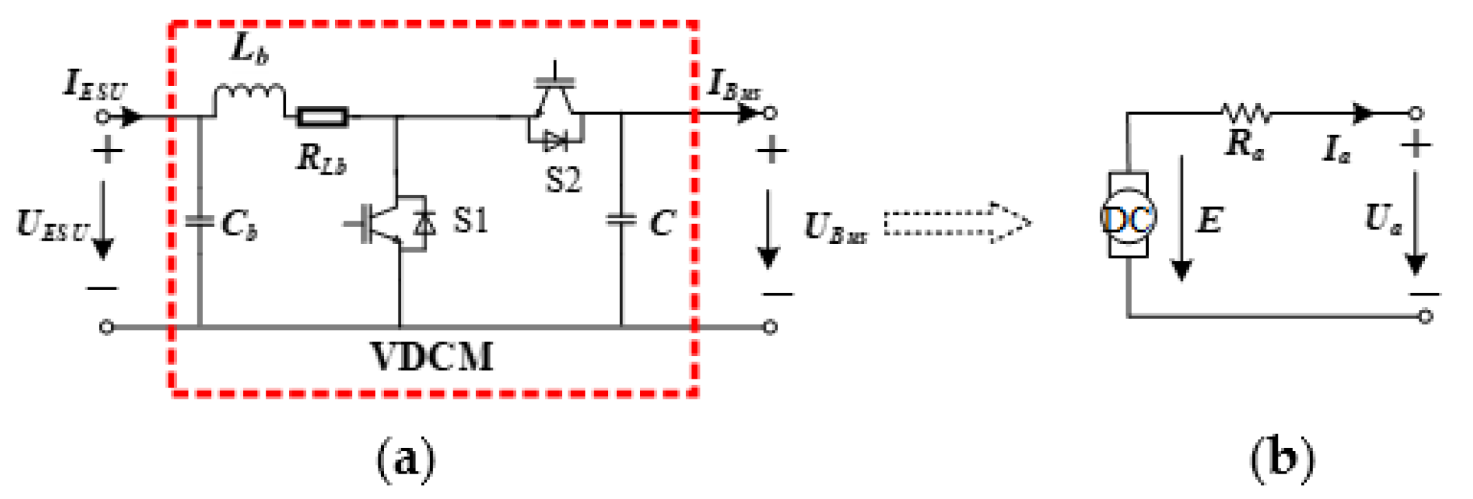
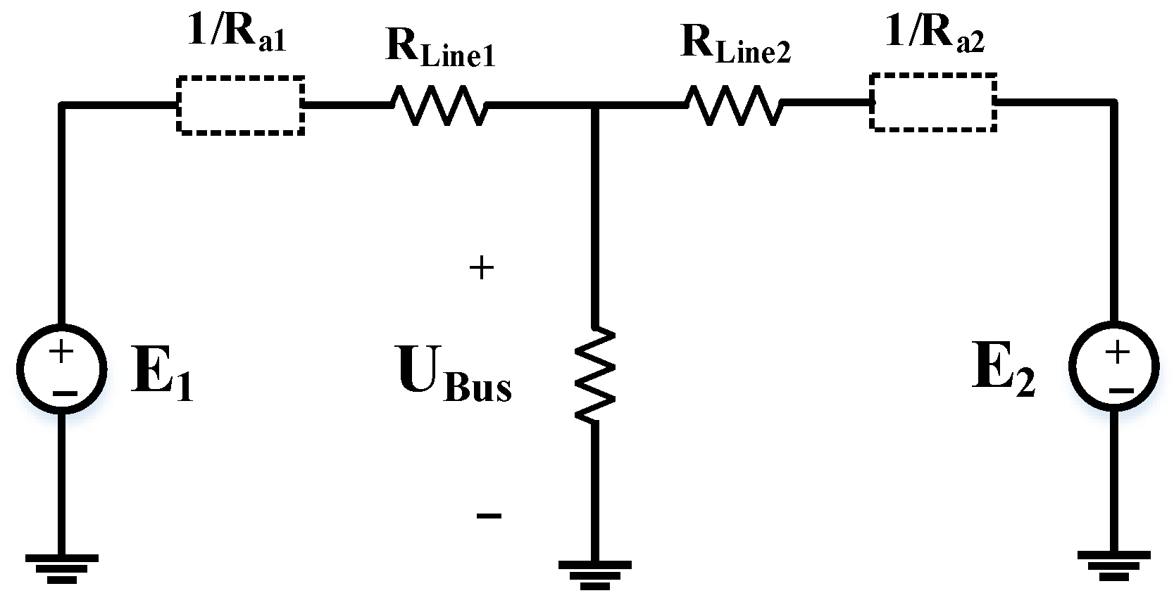
The bidirectional DC-DC converter [
34,
35] is equivalent to a two-port network in
Figure 1a. For the virtual DC machine, the left port is connected to the ESU and the right port is connected to the DC bus. The DC-DC bidirectional converter has two operating states, which are boost and buck. When the DC-DC converter is in the boost state, the left port is the input port and the right port is the output port in
Figure 1a. After VDCM control, the output port of the bidirectional DC-DC converter can show the droop and dynamic characteristics of the DC machine. In other words,
UBus in
Figure 1a has the same characteristics as
Ua in
Figure 1b. When the DC-DC converter is in the buck state, the situation is reversed.
UESU in
Figure 1a has the same characteristics as
Ua in
Figure 1b.
The EMF balance equation of the VDCM armature loop is shown in
Figure 1b [
36]:
where
Ua is the terminal voltage of the DC machine,
Ia is the terminal current of the DC machine, and
Ra is the armature resistance.
E is the armature EMF of DC machine,
CT is the torque coefficient,
is the flux, and
is the angular velocity.
UESU is the voltage of the ESU,
IESU is the current of the ESU,
UBus is the voltage of the bus, and
IBus is the current of the bus.
Lb is the output inductance of the DC-DC converter,
rLb is the output resistance of the DC-DC converter, and
Cb is the output capacitor of the DC-DC converter.
2.1. A Bidirectional VDCM Control with ESU
For the VDCM, the mechanical equation is [
37]:
where
J is the inertia time constant of the VDCM;
Tm and
Te are the mechanical torque and the electromagnetic torque of the VDCM;
D is the damping constant of the VDCM; and
is the rated angular velocity of the VDCM. The VDCM is divided into two working states: the virtual DC generator (VDG) state and the virtual DC motor (VDM) state. In the VDG state,
Tm becomes a turbine torque. At the same time, the ESUs connected to the bidirectional DC-DC converters are in the discharging state. Otherwise,
Tm becomes a load torque, which is opposed by
Te. At the same time, the ESUs connected to the bidirectional DC-DC converters are in the charging state.
The electromagnetic power of the DC machine is:
The electromagnetic torque is:
Similarly, the mechanical torque is:
where
Pm is the mechanical power.
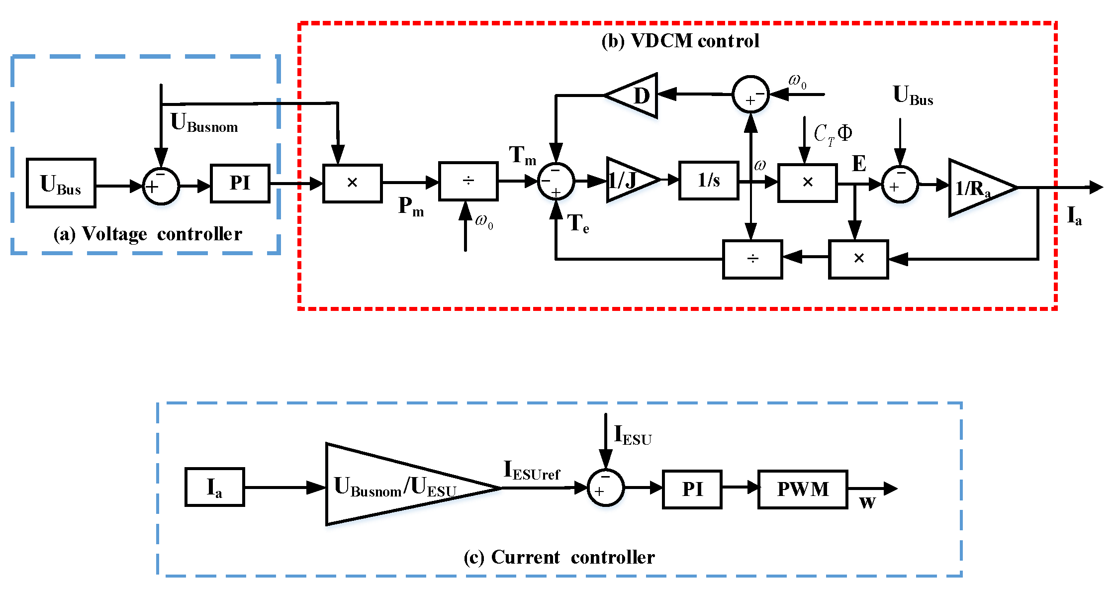
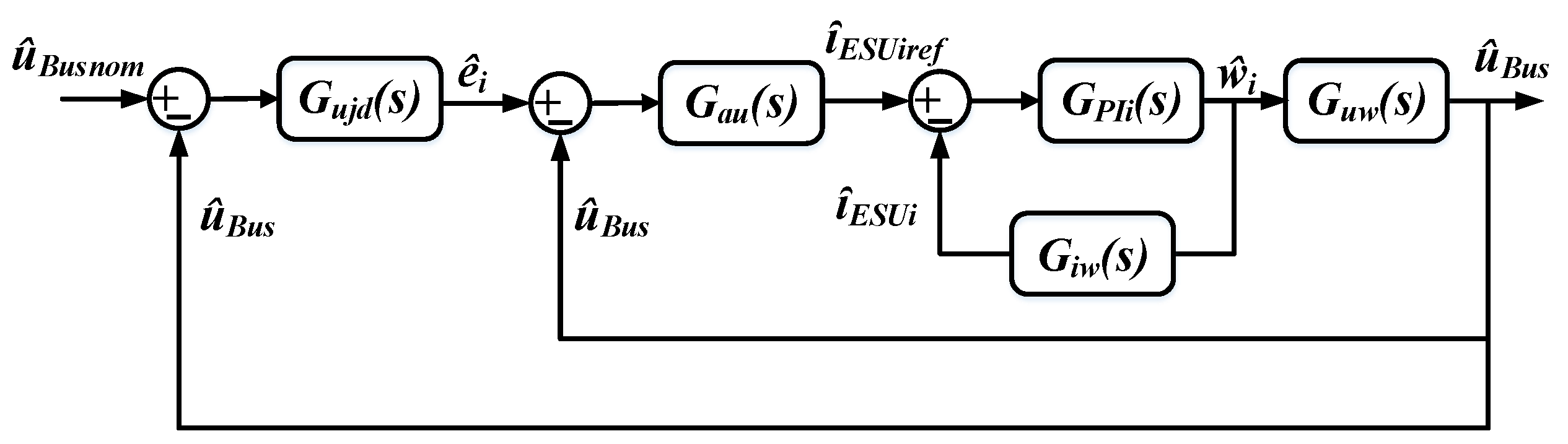
Combining (1)–(6), the control block diagram of the VDCM with the ESU is given in
Figure 2b. The double closed-loop constant voltage control of a bidirectional DC-DC converter is used in the ESU interface, and the control block diagram is shown in
Figure 2a,c. The stability of the DC bus voltage can be maintained through the adjustment of the outer loop of the DC bus voltage and the inner loop of the current, where
UBusnom is the normal value voltage of the bus,
IESUref is the reference current of ESU, and
w is the duty ratio.
In order to enhance the inertia and damping characteristics of the DC microgrid and improve the stability of the bus voltage, the VDCM control is added on the basis of the double closed-loop constant voltage control. In
Figure 2, the actual value of the bus voltage and the normal value of the bus voltage are compared in the voltage controller, and the voltage PI controller is also used to generate mechanical power
Pm while keeping the bus voltage stable. Therefore, mechanical power
Pm is
UBusnom (
kp +
ki/s)(
UBus −
UBusnom). According to the mechanical rotation equation of the DC machine and the balance equation of the armature circuit electromotive force, the inertia and damping characteristics of the DC machine can be simulated by VDCM control. Therefore, the dynamic characteristics of the DC bus voltage can be improved. Based on the power balance principle, in current control, the armature current is converted to the ESU reference current through the
UBusnom/UESU module, and the ESU reference current is used to track the ESU current. The desired control signal is finally obtained through a current PI controller and a PWM modulation.
2.2. An Improved Bidirectional VDCM Control with ESU
The traditional VDCM control needs to obtain mechanical power and electromagnetic power according to the voltage PI controller and (4), and they are converted into electromagnetic torque and mechanical torque by (5) and (6). In SOC balance control, the main role of the VDCM is to provide virtual armature EMF, inertia, and damping characteristics by (2) and (3). Therefore, when the VDCM control is used for SOC balancing, the power loop and the torque loop have little significance in SOC balancing. Furthermore, according to [
38], the results can be obtained as follows:
where
kf is a constant.
According to (3) and (7), we can obtain:
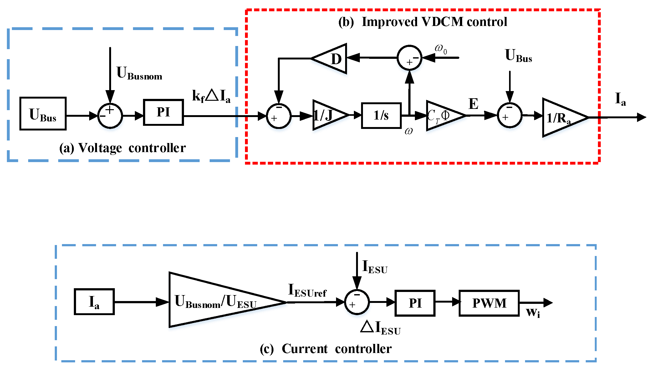
Therefore, by combining (1), (2), and (8), an improved bidirectional VDCM control lacking power loops and torque loops is introduced for SOC balancing in
Figure 3b. The voltage PI controller is used to generate
kfia in
Figure 3a while keeping the voltage stable. Similar to the bidirectional VDCM control with ESU in
Figure 2, the control block diagram of improved bidirectional VDCM with ESU is given in
Figure 3. Compared with the traditional VDCM control, by combining (2) and (8), mechanical power, electromagnetic power in (4), electromagnetic torque in (5), and mechanical torque in (6) can be removed while virtual armature EMF, inertia, and damping characteristics are guaranteed.
In addition, when there is a sudden change in load or power supply, the bus voltage will have a dying oscillation. The bus voltage dying oscillation is generally divided into four states as shown in
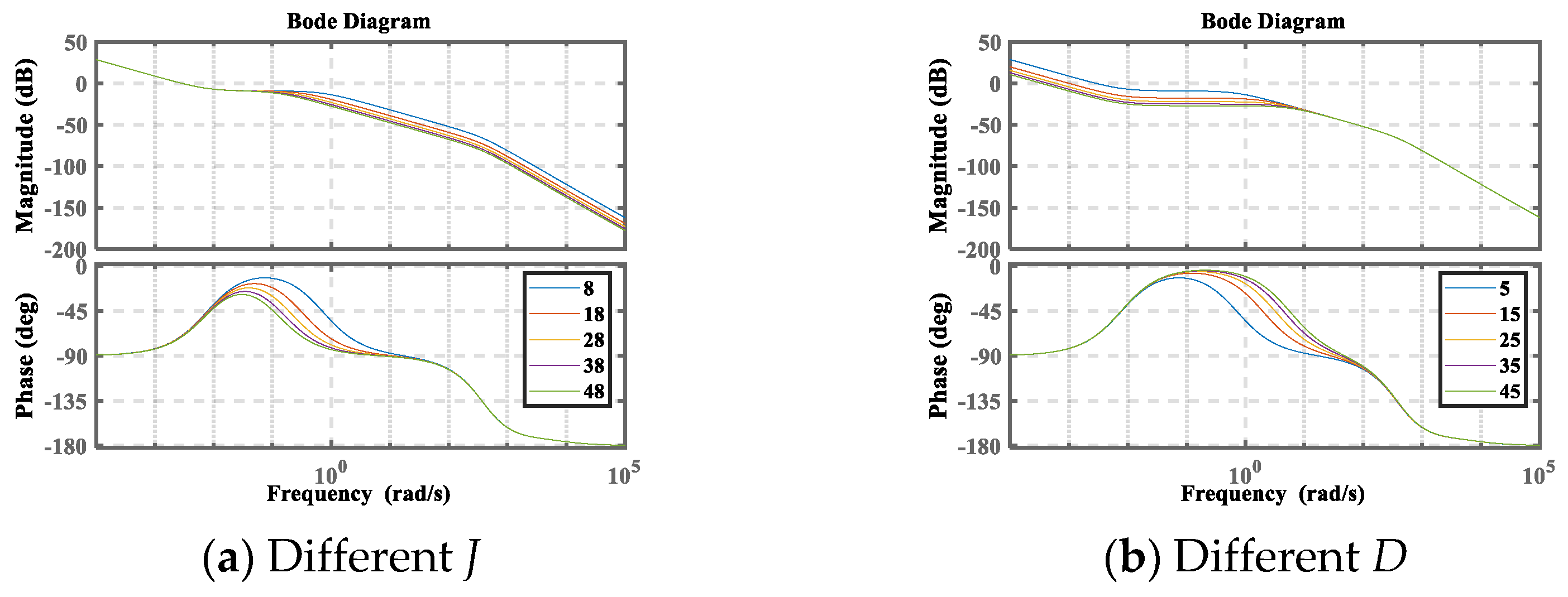
Table 1. By injecting a virtual inertia into the DC microgrid system, the bus voltage fluctuation caused by load change on the DC bus can be buffered. The inertia time constant
J and damping constant
D play different roles in suppressing the decay oscillation of voltage [
26]. However, there is some conflict between constant
J and constant
D in suppressing voltage fluctuation and voltage recovery. The adaptive
J and
D can solve this problem effectively. At present, there have been some research results on parameter adaptive control of AC VSM control [
25,
26,
27]. However, for the traditional VDCM control,
J and
D are generally constant. The influence of
J and
D on suppressing bus voltage fluctuation is often ignored in VDCM control with constant parameters. There is still a lack of research on VDCM control with adaptive
J and
D. In addition, adaptive
J and
D are designed by analyzing the state of bus voltage dying oscillation.
From
Table 1, we can see that the bus voltage deviation in state 1 and state 4 is continuously increasing. Hence, reducing the bus voltage deviation is the primary key. Since a larger
J can reduce the bus deviation difference change rate, a term related to the bus voltage difference change rate is added to the steady-state value
J0 in these two stages to suppress the bus voltage deviation increase. Meanwhile,
D remains a steady-state value. This is because a larger
D will increase the bus deviation. In state 2 and state 3, reducing the oscillation of the bus voltage deviation is the primary key. Therefore, a larger
D is required to suppress the bus voltage oscillation. Therefore, we add a term related to the bus voltage deviation on the basis of the steady-state value
D0. Meanwhile,
J remains a steady-state value in state 2 and state 3.
After the above analysis result, in this paper, adaptive
J and
D related to bus voltage difference
UBus and bus voltage difference change rate
dUBus/
dt are designed as
where
kj and
kd are the regulation coefficients of
J and
D, respectively, and
J0 and
D0 are the steady-state value of
J and
D, respectively.
In summary, the improved bidirectional VDCM control proposed in this paper has two improvements. Firstly, compared with the traditional VDCM control, the improved bidirectional VDCM control removes the power loop and torque loop. Secondly, the improved bidirectional VDCM control adopts adaptive J and D related to the bus voltage difference and the bus voltage difference change rate. Compared with traditional VDCM control, the improved bidirectional VDCM control can suppress bus voltage oscillation adaptively to enhance inertia and damping characteristics.
5. Simulation Results
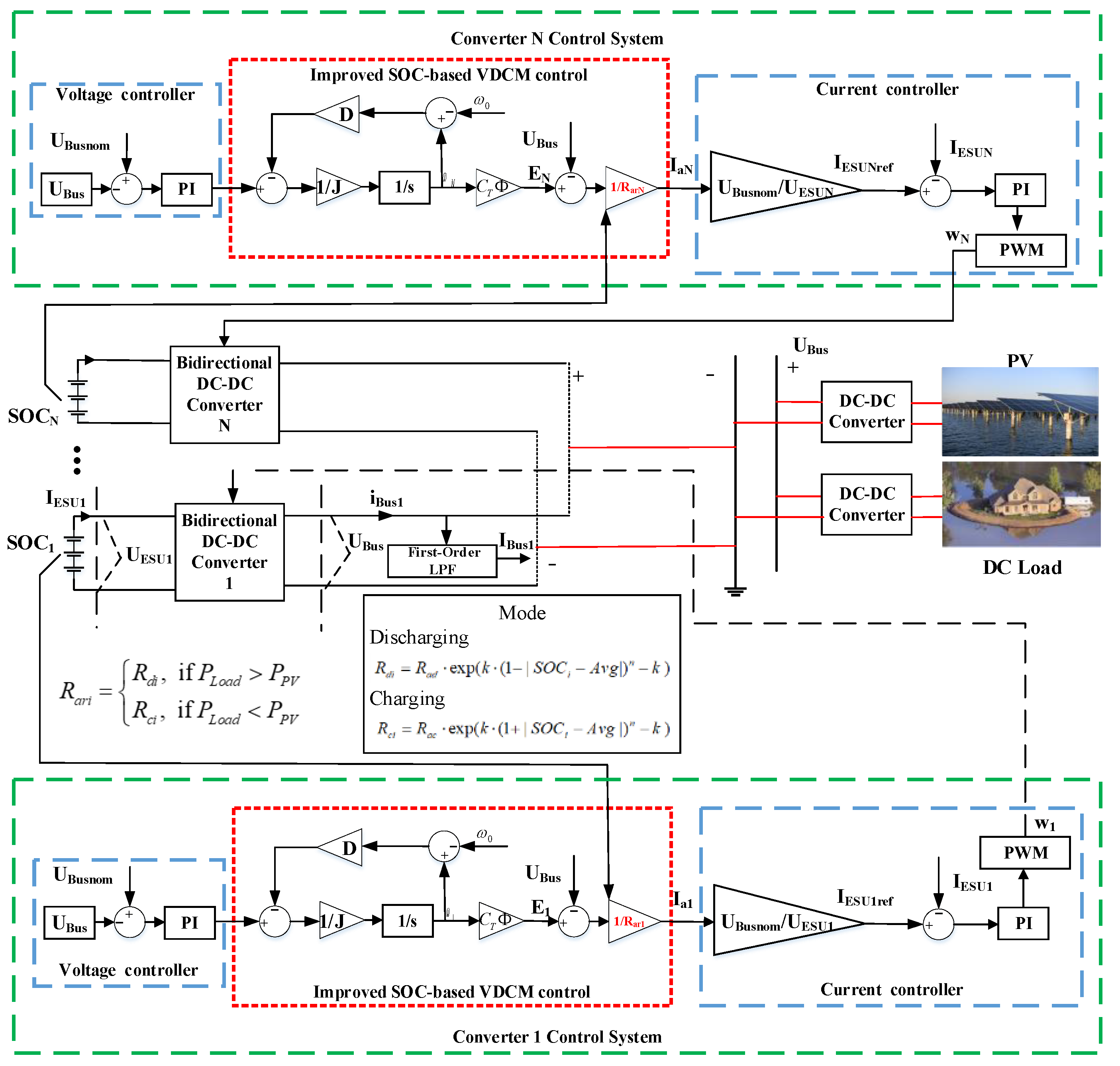
In order to prove the effectiveness of the proposed control, simulations will be carried out in this section. The offshore isolated island DC microgrid system involved in the simulations is shown in
Figure 5, and the DC microgrid system contains ESUs, a renewable energy source (PV), and a DC load. Detailed system parameters are shown in
Table 2. This section will be divided into three cases. Case 1, Case 2, and Case 3 adopted the same DC microgrid system and working conditions. The method used in Case 1 is the improved SOC-based bidirectional virtual DC machine control in this paper. The method used in Case 2 is the SOC-based bidirectional virtual DC machine control in [
24]. The method used in Case 3 is the double-quadrant SOC-based droop control in [
15]. The comparative results of the three cases are also analyzed in this section. In addition, comparisons of bus voltage in different VDCM control, the influence of line impedance on SOC balancing, the influence of disturbances, and plug-and-play are also included in this section to verify the effectiveness and superiority of the proposed control.
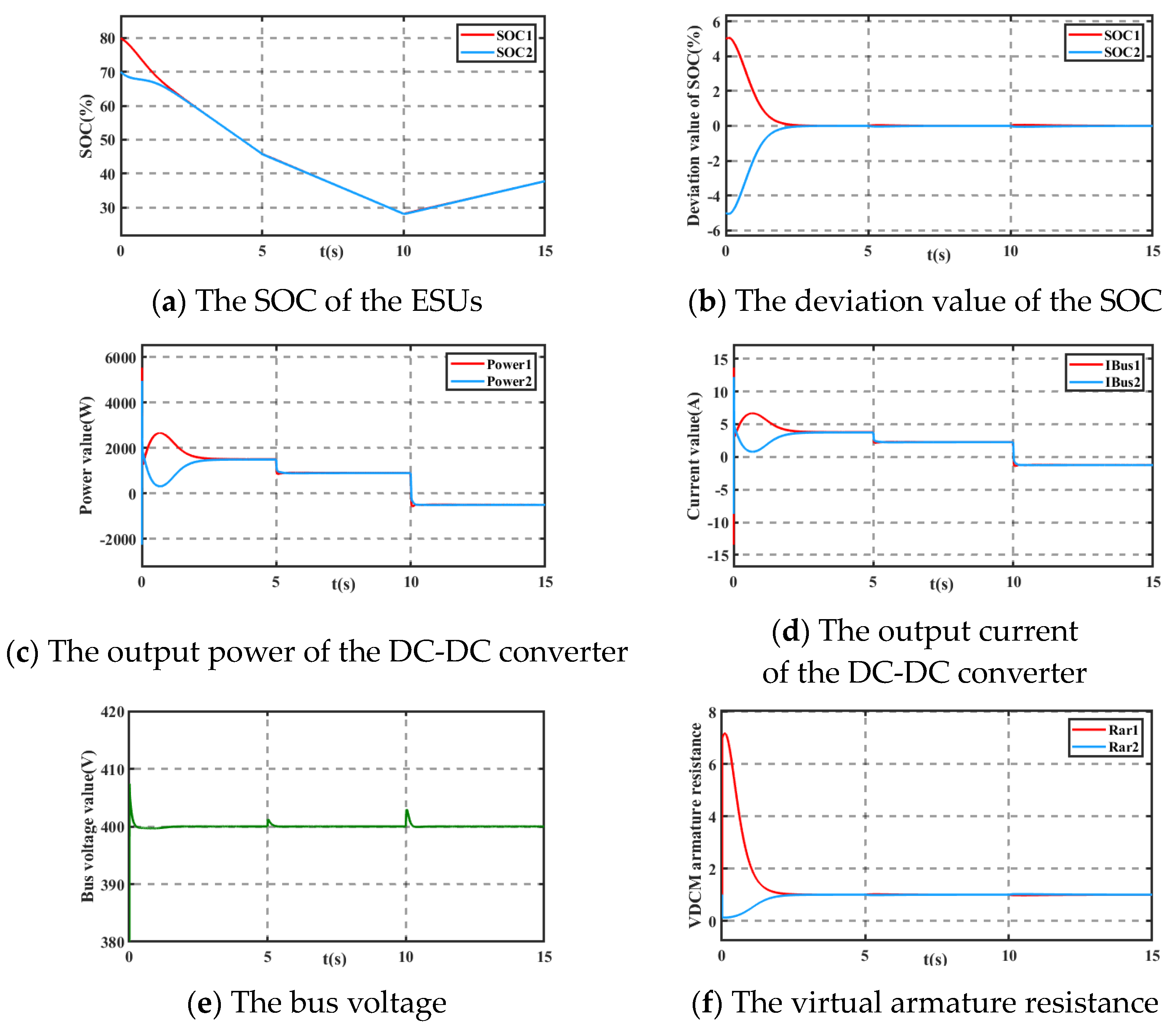
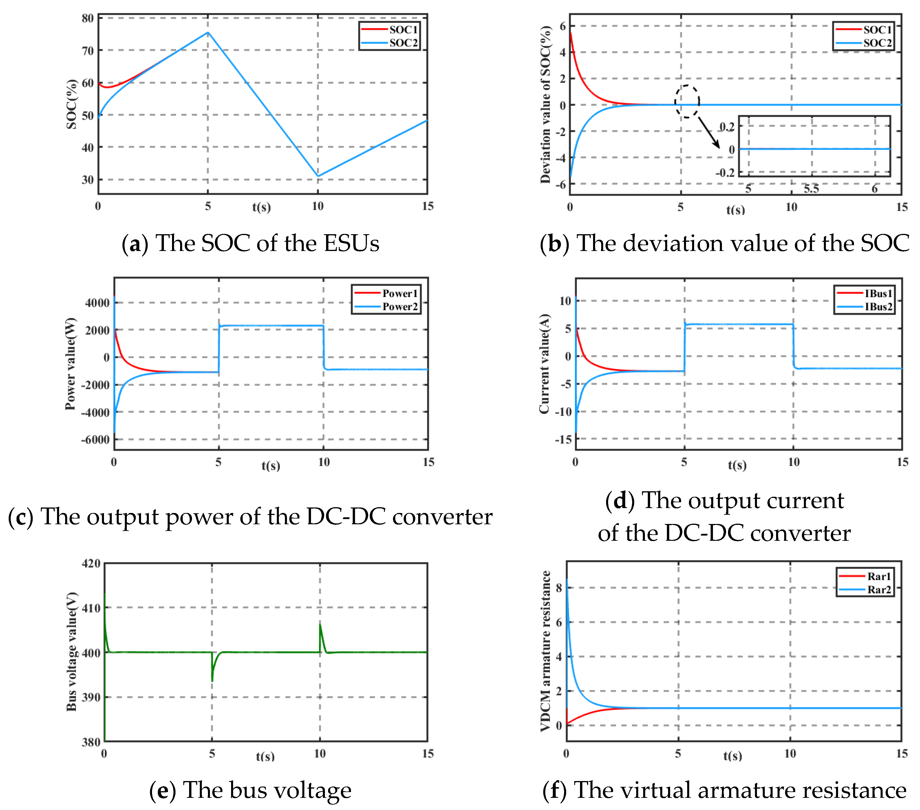
5.1. Case 1: The Proposed Control Method in the Paper
The PV is controlled by maximum power point tracking (MPPT), and the PV power remains constant. The load power is set as a piecewise function, which is used to simulate the change of load in the actual process. PLoad and PPV are shown in (33).
From 0 s to 10 s, the working mode of ESUs is in the discharge state. From 10 s to 15 s, the working mode of ESUs is in the charge state. The initial SOCs of the two ESUs are 80% and 70%. In particular, one second in simulation time corresponds to one hour in real time. This same rule applies in the other cases.
From
Figure 10a,b, it can be seen that the proposed control can balance the SOCs of the ESUs within 5 s. The two SOCs of the ESUs are finally in a consistent state, and the deviation value of the SOCs can converge to a minimum value. Because the proposed control in this paper increases the inertia and damping characteristics of the DC microgrid system, when the load changes, the DC bus voltage fluctuation is small, and the DC bus voltage returned to the normal value in a gentle way in
Figure 10e.
In this process, whether it is switching the state between discharging and charging or changing the load power, from
Figure 10c–e, the output power of the bidirectional DC-DC converter, the output current of the bidirectional DC-DC converter, and the bus voltage are within an acceptable range. When the SOCs of ESUs balance, the SOC-based VDCM armature resistances converge to the initial virtual armature resistances in
Figure 10f. In Case 1, the effectiveness of the SOC balance control proposed in this paper is verified.
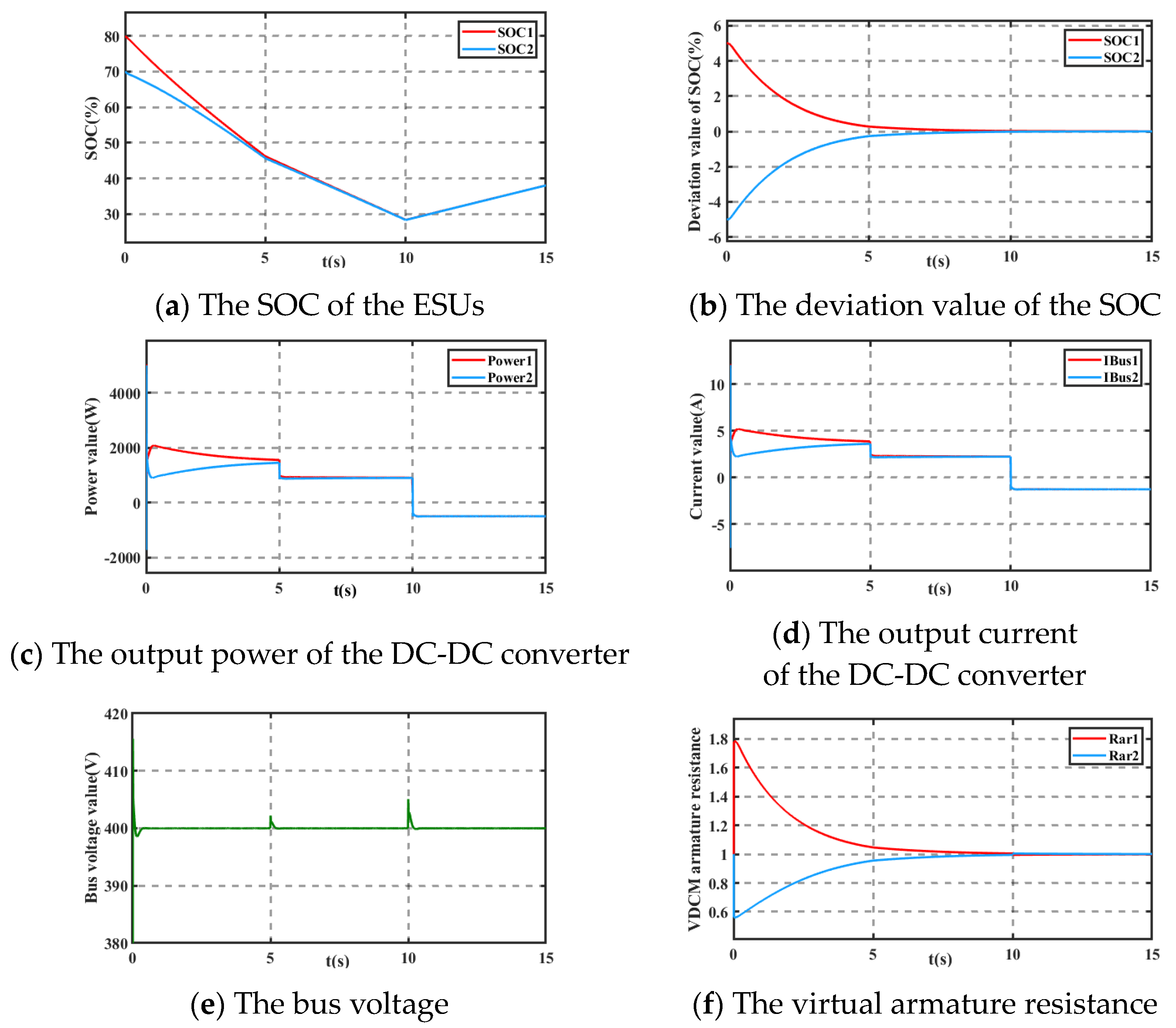
5.2. Case 2: The Control Method in [24]
An SOC-based VDCM control for distributed storage systems in DC microgrids is proposed in [
24]. The control block diagram is shown in
Figure 2. From
Figure 11a,b, it can be seen that the two SOCs are finally in a consistent state within 10 s. From
Figure 11c–e, the output power of the bidirectional DC-DC converter, the output current of the bidirectional DC-DC converter, and the bus voltage are within an acceptable range. When the SOCs reach a balance state, the virtual armature resistance converges to the initial virtual armature resistance in
Figure 11f.
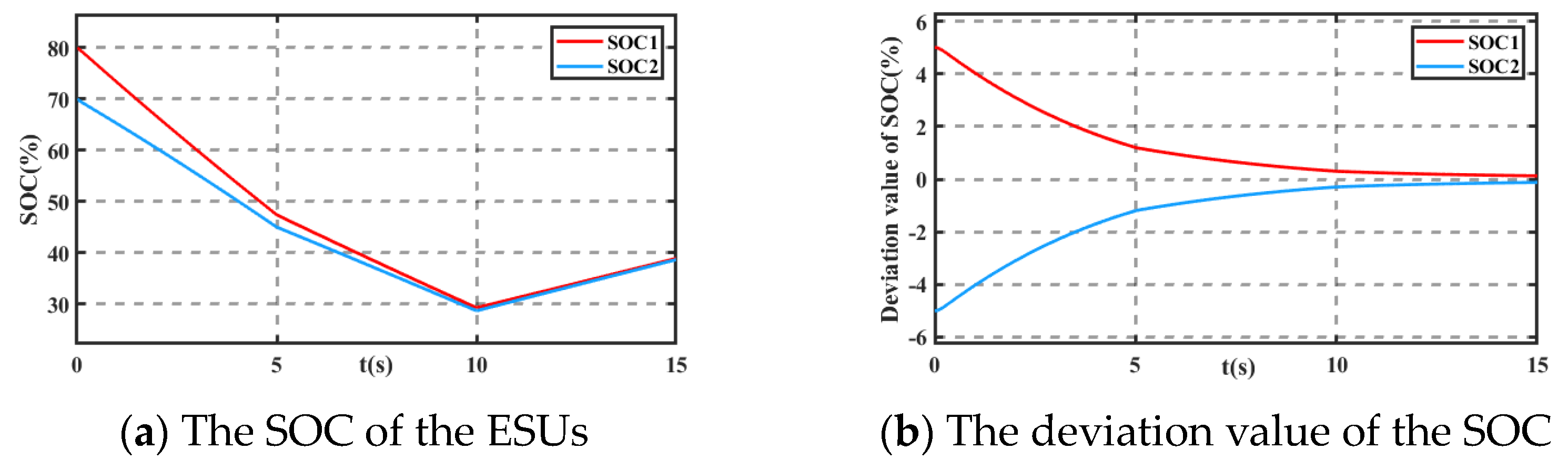
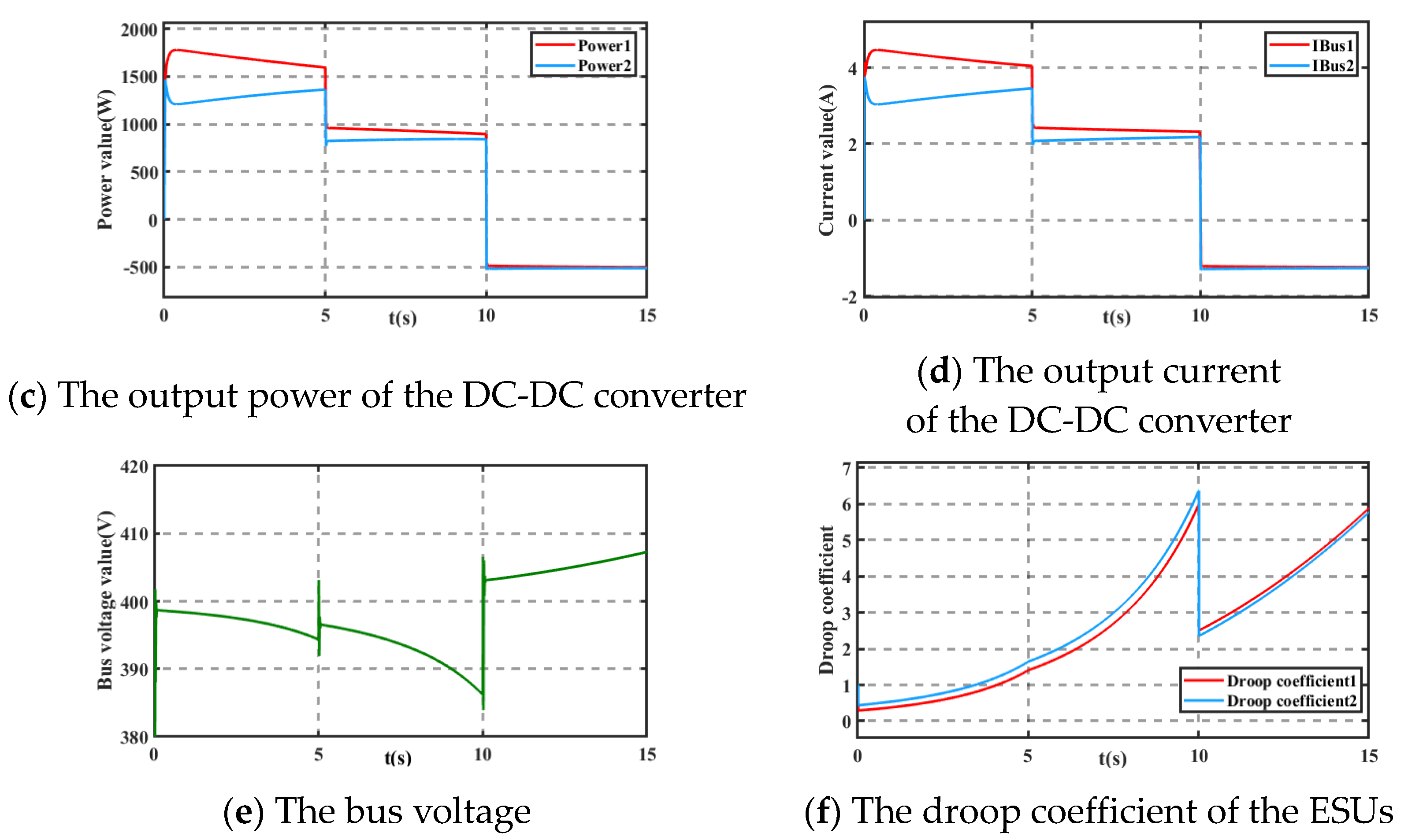
5.3. Case 3: The Control Method in [15]
A double-quadrant SOC-based droop control for distributed storage systems in autonomous DC microgrids is proposed to reach SOC balance in [
15]. From
Figure 12a,b, it can be seen that the two SOCs are almost in a consistent state within 15 s. From
Figure 12c–e, the output power of the bidirectional DC-DC converter, the output current of the bidirectional DC-DC converter, and the bus voltage are within an acceptable range. From
Figure 12f, it can be seen that the droop coefficients change with the SOC value.
Note that, although the power and current of the ESU ports are not given in this paper,
Figure 10c,d,
Figure 11c,d, and
Figure 12c,d can be converted to the ESU ports according to Formula (20). Therefore, in the paper, we only give the current and power output of the converter; correspondingly, they can also reflect the state of the current and power at the ESU ports. Therefore, in order to avoid repetition, only the converter output current and power are given in the paper. The main work of this paper is to achieve SOC balance by power allocation and improve bus voltage dynamics. The figures of the bus voltage diagram and the SOC are given in detail in this paper.
5.4. Comparison Diagram
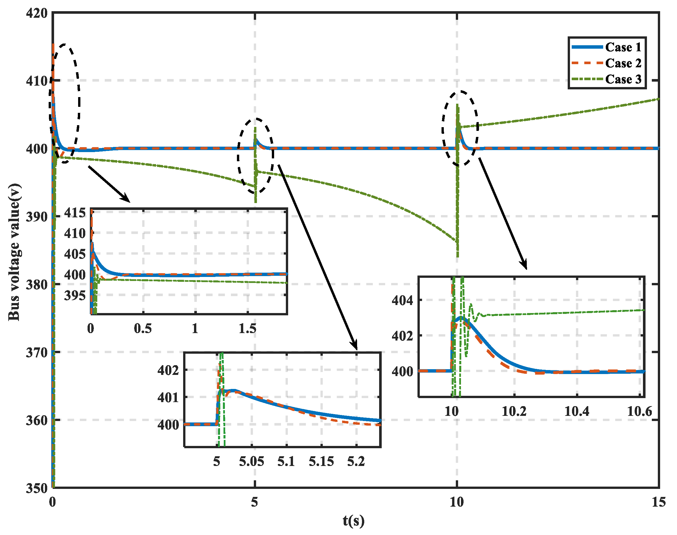
From
Figure 13, we can find that although the bus voltages of the three cases are all within the allowable range, the bus voltage cannot be maintained at a normal value in Case 3. This is because only droop control is used in Case 3, and there is a deviation between the actual bus voltage and the bus voltage normal value. In comparison, the bus voltages of Case 1 and Case 2 can be maintained at the normal value without additional secondary voltage restoration control. From
Figure 13, when the load changes, the bus voltage fluctuation in Case 1 is smaller than in Case 2 and the process of the bus voltage returning to a normal value is gentler. Hence, it can be proven that the improved VDCM control without a power loop and torque loop and with adaptive
J and
D in this paper has better a dynamic effect in suppressing bus voltage fluctuation.
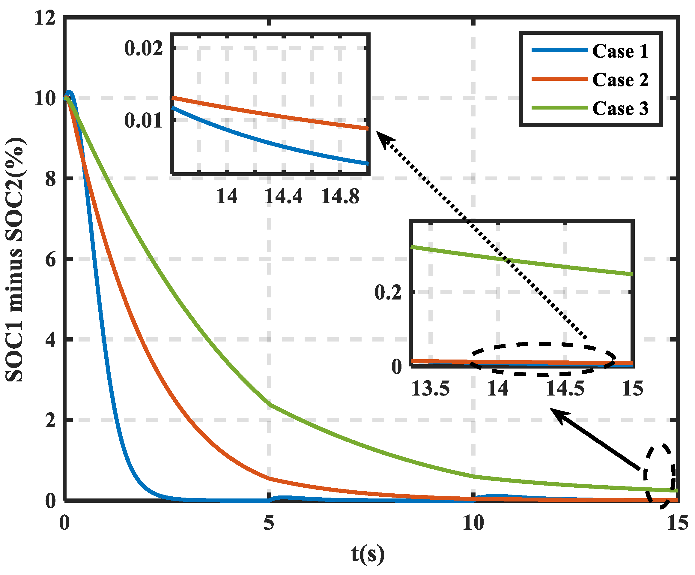
The proposed SOC-based VDCM virtual armature resistance in this paper expands the value range of virtual armature resistance, which makes the SOC-based VDCM virtual armature resistance more sensitive to SOC changes. Therefore, from
Figure 14, we can see that under the same working conditions, the proposed control in this paper achieves SOC balance state within the shortest time. Combined with
Figure 13, even if the value range of the virtual armature resistance increases, the dynamic effect of the bus voltage is still excellent. The results show the effectiveness and superiority of the proposed control in this paper.
In SOC balance control, droop control is the most common control. It is not difficult to find that the principles of traditional droop control (TDC) [
15] and VDCM control [
24] are actually similar. However, TDC only imitates the external characteristics of a generator, without inertia and damping characteristics. This means that VDCM control has stronger inhibition to sudden voltage change than TDC [
12]. This is an advantage of using VDCM control in SOC balancing.
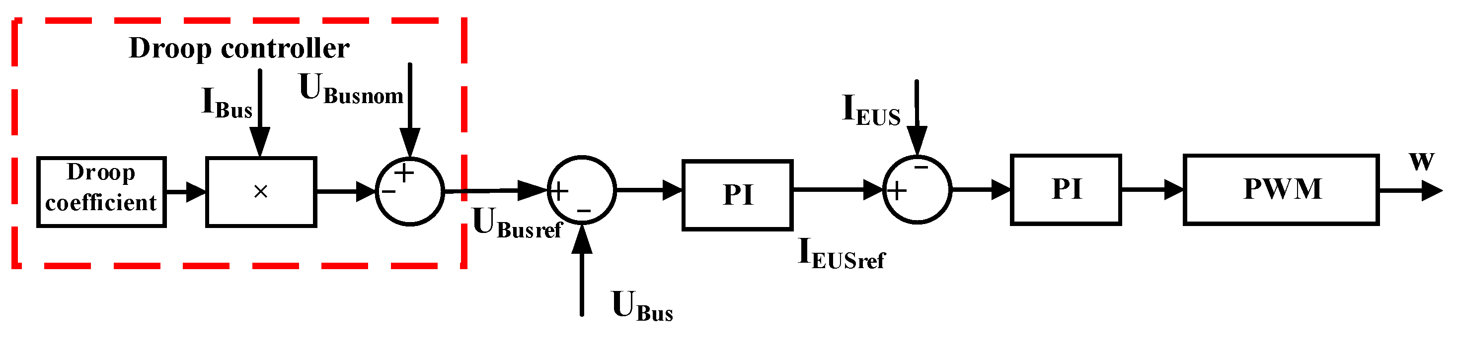
In the TDC from
Figure 15, due to the droop effect, the reference value of the bus voltage is different from the normal value [
18]. In fact, the actual bus voltage varies with the reference value, resulting in a deviation between the actual bus voltage and the normal value. When the ESU is in the discharge state, the actual voltage of the bus is higher than the normal value. On the contrary, when the ESU is in the charge state, the actual voltage of the bus is lower than the normal value. To eliminate the voltage deviation, a secondary control is required to recover the bus voltage at a normal value [
19]. Otherwise, in the droop control, the bus voltage cannot be maintained at the normal value. However, in VDCM control, the voltage controller can ensure that the actual bus voltage always follows the normal value [
24]. Therefore, there is no deviation in the bus voltage in the steady state. This is another advantage of using VDCM control in SOC balancing.
For the proposed control in this paper and the traditional VDCM control in [
24], the proposed control removes the power loop and torque loop, making the improved VDCM conform more to DC machine working principles. In addition, the adaptive
J and
D are introduced to make the proposed control more effective in suppressing voltage fluctuations. This conclusion can be verified from
Figure 13. In addition, in
Table 3, we take the bus voltage fluctuation at t = 5s as an example. It can also be seen that the proposed control in this paper has a better effect in suppressing bus voltage fluctuation.
5.5. Comparisons of Bus Voltage in Different VDCM Control
In this part, we will compare the traditional VDCM control in [
24], the VDCM control with adaptive
J and
D in this paper, the VDCM without a power loop and a torque loop, and the proposed VDCM control in this paper on the dynamic characteristic effect of the DC bus voltage. The experimental conditions of all schemes are the same as Case 1.
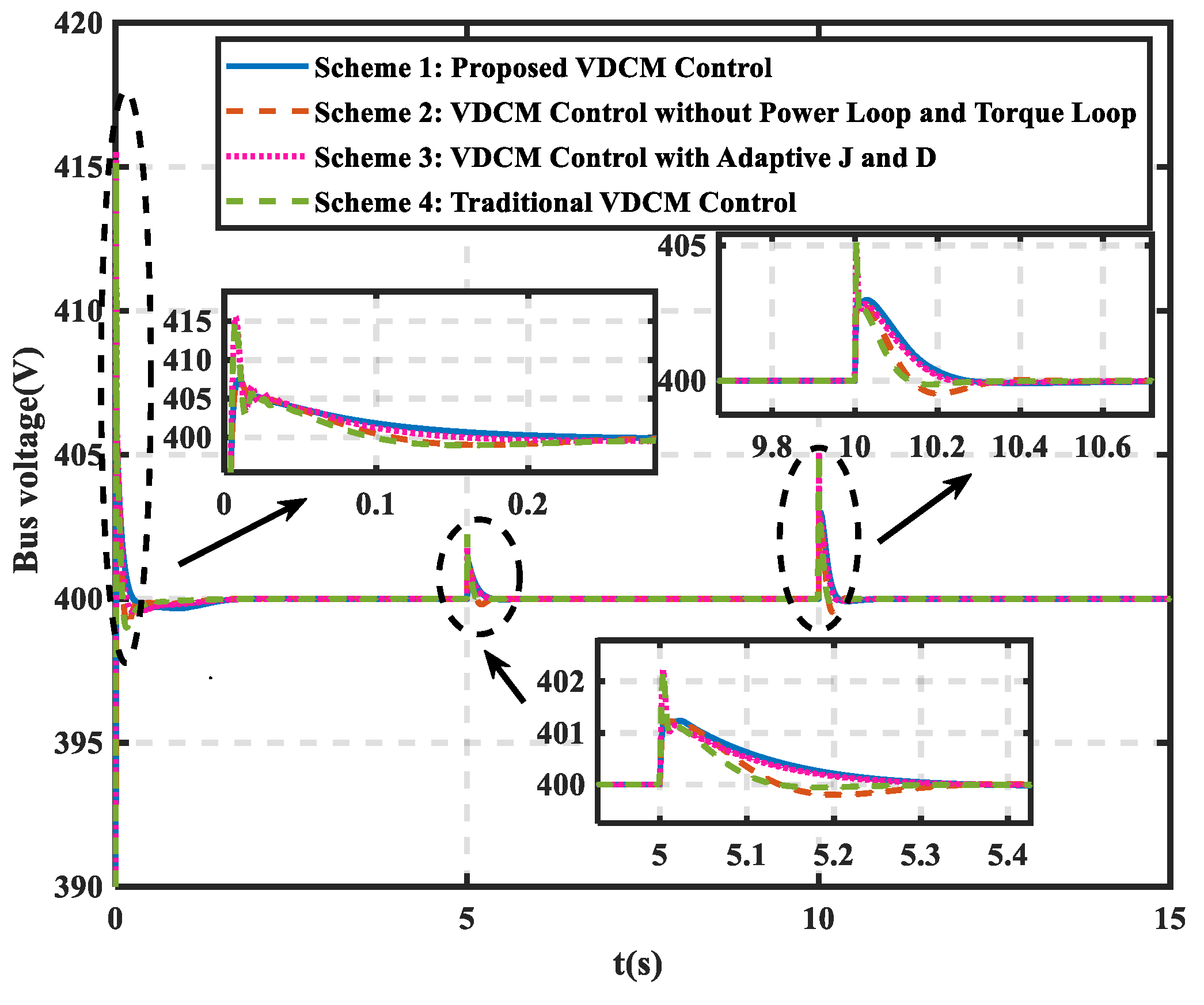
In
Figure 16, compared with Schemes 1 and 2 in
Figure 16 and Schemes 3 and 4 in
Figure 16, it can be found that the bus voltage fluctuation amplitude of Schemes 1 and 2 in
Figure 16 is small, which indicates that the VDCM control scheme without a power loop and torque loop has a better effect in reducing the bus voltage fluctuation amplitude. The traditional VDCM control needs to establish mechanical power through the voltage controller in
Figure 2. When the DC microgrid system is disturbed, the mechanical power will fluctuate. However, the improved control scheme without a power loop and torque loop needs to establish a current through the voltage controller in
Figure 3. When the DC microgrid system is disturbed, the current will fluctuate. Therefore, compared with power fluctuation or current fluctuation when the DC microgrid is disturbed, the current fluctuation is obviously smaller, so the VDCM control scheme without a power loop and torque loop has a better effect in reducing the bus voltage fluctuation amplitude.
In addition, compared with Schemes 1 and 3 in
Figure 16 and Schemes 2 and 4 in
Figure 16, it can be found that the VDCM control with adaptive
J and
D can make the bus voltage return to a normal value in a gentler way. When the DC microgrid system is disturbed,
J or
D will increase according to the rules in
Table 1. A larger
J or
D can enhance the inertia or damping characteristics of the system; therefore, compared with the control scheme without adaptive
J and
D, the control scheme with adaptive
J and
D has an outstanding effect on suppressing the bus voltage fluctuation.
Compared with other control schemes, the control scheme proposed in this paper is one control that removes the power loop and torque loop with adaptive J and D. Therefore, the scheme proposed in this paper can improve the dynamic characteristics of bus voltage from two aspects, that is, reducing the bus voltage fluctuation amplitude and suppressing bus voltage fluctuation, which has a significant influence on the dynamic effect of improving the bus voltage.
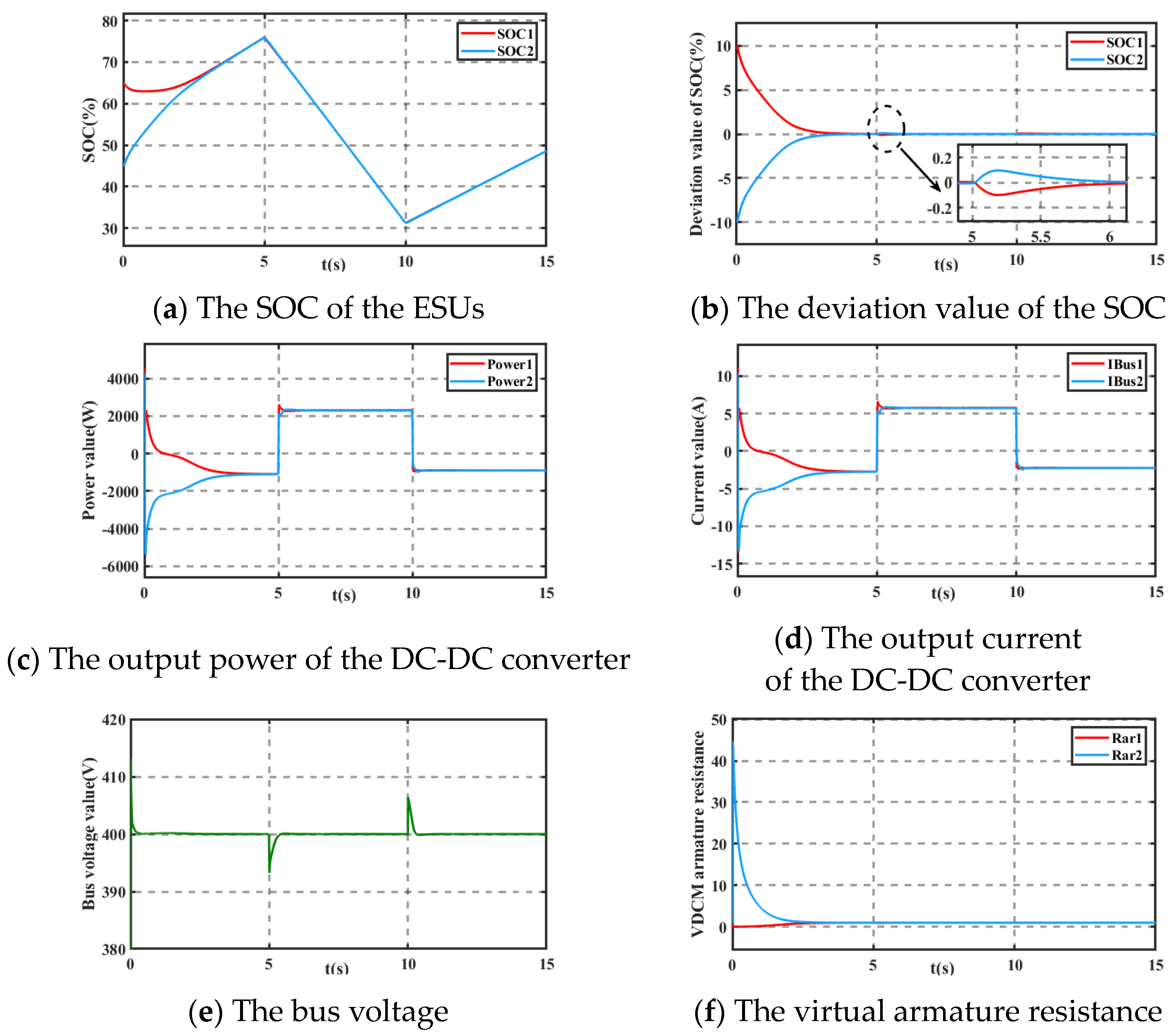
5.6. Influence of Line Impedance on SOC Balancing
An equivalent microgrid with two ESUs is shown in
Figure 17. In fact, the essence of armature resistance is actually virtual resistance. Then, the total impedance on the actual transmission line is the sum of the armature resistance and the line impedance. The armature electromotive force
E in (2) is introduced into VDCM control. The armature electromotive force
E can adjust adaptively to an appropriate voltage value according to the line impedance and armature resistance value. The voltage value of the supply side will not be reduced due to the existence of line impedance, so the bus voltage will not drop. Therefore, the influence of line impedance can be ignored by using the scheme proposed in this paper. Next, we will set up two simulation cases to verify the above conclusions.
Case (1): The PV is controlled by maximum power point tracking (MPPT), and the PV power remains constant.
PLoad and
PPV are shown in (34). From 0 s to 5 s, the working mode of the ESUs is in the charge state. From 5 s to 10 s, the working mode of the ESUs is in the discharge state. From 10 s to 15 s, the working mode of the ESUs is in the charge state. The initial SOCs of the two ESUs are 60% and 49%. Line impedance
RLine1 and
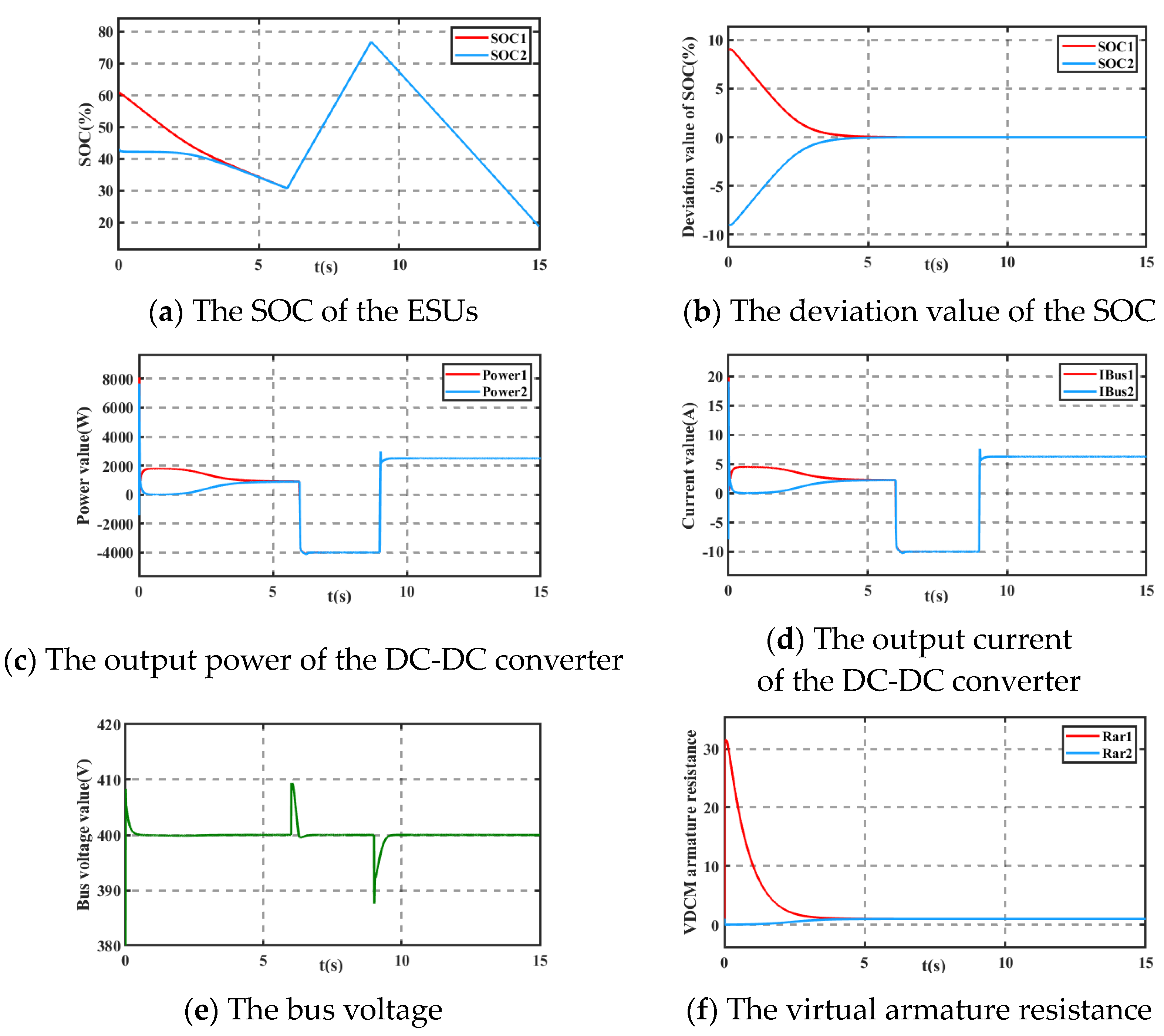
RLine2 are 0.05Ω. Case (2):
PLoad and
PPV are the same as in Case 1. The initial SOCs of the two ESUs are 65% and 45%. Line impedance
RLine1 is 0.05Ω, and line impedance
RLine2 is 0.5Ω.
From
Figure 18a,b and
Figure 19a,b, it can be seen that the proposed control can balance the SOCs of the ESUs. By comparing
Figure 18b and
Figure 19b, it can be seen that if
RLine1 and
RLine2 are not equal, the SOCs will be unequal for a short time when the ESU states are switched. However, under the control proposed in this paper, the SOCs will eventually reach a consistent state, and the deviation value of the SOCs can converge to a minimum value.
From
Figure 18c–e and
Figure 19c–e, the output power of the bidirectional DC-DC converter, the output current of the bidirectional DC-DC converter, and the bus voltage are within an acceptable range. When the SOCs reach a balance state, the virtual armature resistance converges to the initial virtual armature resistance in
Figure 18f and
Figure 19f.
To sum up, it can be seen from Case (1) and Case (2) that SOCs can reach a consistent state no matter if the line impedances are the same or different. Therefore, the influence of line impedance on SOC balancing can be ignored by using the control proposed in this paper.
5.7. Influence of Disturbances
The PV is controlled by maximum power point tracking (MPPT), and the PV power remains constant.
PLoad and
PPV are shown in (35):
From 0 s to 6 s, the working mode of the ESUs is in the discharge state. At 6 s, the 36.57% load is removed, and the state of the ESUs changes from discharge to charge. At 9 s, the 76.47% load is added, and the state of the ESUs changes from charge to discharge. Here, we consider relatively large load variations to verify the performance of the proposed control method, which may be rare in reality. The initial SOCs of the two ESUs are 61% and 43%. The disturbance referred to in this part is a change of load.
From
Figure 20, it can be seen that the DC microgrid system can still maintain stability when it is suffering from relatively large disturbances. In addition, from
Figure 20a,b, the proposed control can balance the SOCs of the ESUs.
5.8. Plug-and-Play
The PV is controlled by maximum power point tracking (MPPT), and the PV power remains constant.
PLoad and
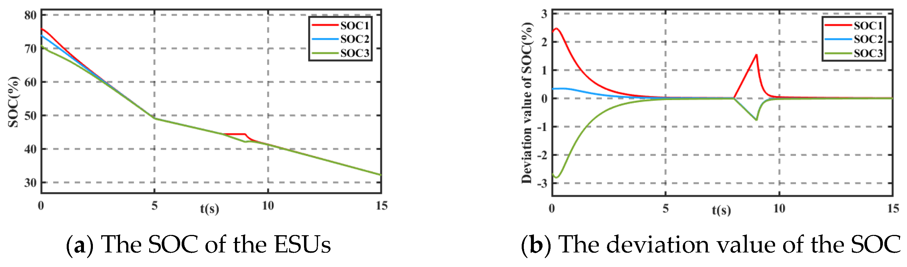
PPV are shown in (36). From 0 s to 15 s, the working mode of the ESUs is in the discharge state. The initial SOCs of the three ESUs are 76%, 74%, and 71%.
From
Figure 21a, it can be seen that when the time
t is 8 s, ESU1 is removed from the DC microgrid system, and when time
t is 9 s, EUS1 is re-connected to the DC microgrid system. Therefore, SOC1 remains unchanged at 8s~9s, while SOC2 and SOC3 continue to decline. It can also be seen from
Figure 21b that when the EUS is removed or reconnected to the DC microgrid system, all SOCs of the ESUs can finally achieve a consistent state under the control proposed in this paper. The simulation case verifies the plug-and-play capability of the proposed control.
6. Conclusions
In this paper, an SOC-based bidirectional VDCM control for energy storage systems in offshore isolated island DC microgrids is presented. Compared with traditional VDCM control, the proposed control removes the power loop and torque loop. Moreover, the J and D used in this paper can adaptively adjust according to the bus voltage difference and the bus voltage difference change rate. The results showed that the VDCM control without a power loop and torque loop has a better effect in reducing the bus voltage fluctuation amplitude. And the control with adaptive J and D has an outstanding effect on suppressing bus voltage fluctuation. Therefore, the scheme proposed in this paper can improve the dynamic characteristics of the bus voltage from two aspects, that is, reducing the amplitude of bus voltage fluctuation and suppressing bus voltage fluctuation, which has a significant influence on the dynamic effect of improving bus voltage.
In addition, in order to shorten the SOC balance time, an improved SOC-based VDCM virtual armature resistance, which is attached to an SOC-related function to the initial virtual armature resistance, is adopted. Therefore, it can adaptively adjust the energy absorbed or released according to the SOC state. The results show that, compared with other control methods, using the improved SOC-based VDCM control in this paper, the dynamic effect of bus voltage is better and SOC balancing can be achieved in a short time.
The research in this paper can provide a reference for the improved application of VDCM control and the SOC balance control of ESUs. However, the bidirectional DC-DC converter used in this paper is the most basic. In the future, we can explore the relationship between SOC balance and converter structure as the research direction.


