Article

Analysis of FPSO Motion Response under Different Wave Spectra

1
School of Naval Architecture, Dalian University of Technology, Dalian 116024, China
2
China Ship Scientific Research Center, Wuxi 214082, China
3
State Key Laboratory of Coastal and Offshore Engineering, Dalian University of Technology, Dalian 116024, China
*
Author to whom correspondence should be addressed.
J. Mar. Sci. Eng. 2023, 11(7), 1467; https://doi.org/10.3390/jmse11071467
Submission received: 12 June 2023 / Revised: 9 July 2023 / Accepted: 17 July 2023 / Published: 23 July 2023
(This article belongs to the Section Ocean Engineering)

Abstract

:
A variety of floating structures at sea play a vital role in the exploitation and utilization of marine resources. The study about interactions between waves and structures is necessary for the impact of the harsh marine environment on the motion and service life of structures. Currently, most studies about the seakeeping of structures are based on simplified regular waves. Because the regular waves do not truly restore the actual wave conditions at sea, the simulation of irregular waves has great practical importance to the study of interactions between waves and structures. Based on the potential flow theory and high-order boundary element method (HOBEM), a Fortran code is developed in this paper and named as SWBI (Solver for Wave–Body Interactions). This program consists of the following two parts: a time–domain numerical model about interactions between waves and 3D structures is based on weakly nonlinear method, and a numerical model about simulation of the nonlinear regular waves, the long-crested irregular waves, and the short-crested irregular waves. This Fortran code is used to simulate the motion of Floating Production Storage and Offloading (FPSO) under three different ocean wave spectra (including ITTC two-parameters spectrum, JONSWAP spectrum and the most likely spectral form of Ochi-Hubble) and found that: To a certain extent, the difference in the motion of FPSO under different wave spectra have a connection with different type of wave, sea conditions and incident angle. The difference in roll of FPSO is quite significant in short-crested irregular waves. The range of FPOS’s roll under the JONSWAP spectrum is the largest when the incident angle is 30°, and range of FPOS’s roll under the most likely spectral form of Ochi-Hubble is the largest when the incident angle is 90°.

1. Introduction

With the continuous deepening of ocean research, the study of the interaction between waves and structures has great scientific significance [1]. Meanwhile, the nonlinearity of realistic ocean waves is becoming stronger, and the movement laws are also becoming more complex. The analytical expression of simplified regular waves to simulate incident waves can no longer meet the needs of deep-sea research. Based on this, the simulation of irregular waves emerged. The concept of significant wave height was first proposed by Sverdrup and Munk during World War II and was used for wind and wave forecasts. Later, Pierson [2] combined the principles and methods of radio noise with Neuman’s energy spectrum research to develop a method for simulating and predicting irregular waves, which further developed into the directional spectrum theory. Currently, the most widely used ocean wave model is the Longuet-Higgins model, which assumes that the incident wave surface at a point on the sea surface is composed of many cosine waves with different phases and amplitudes [3]. On this basis, Longuet-Higgins also provided a probability prediction approach for important parameters such as extreme wave height. In recent years, the simulation and prediction of random waves have been widely used in the field of ocean engineering.
Currently, the irregular waves can be primarily classified into two categories: long-crested waves and short-crested waves. The main difference between them is in whether multi-directional factors are taken into consideration. Short-crested waves, due to their directional spreading, result in a more complex motion response in structures compared to long-crested waves [4]. The commonly used wave spectra include Neman spectrum [5], P-M spectrum [6], JONSWAP spectrum [7] and ITTC two-parameters spectrum [8]. Many scholars have conducted extensive research in this field. Hua et al. [9] conducted a study on the strong nonlinear rolling performance of ships in random waves using the long-crested irregular wave based on linear theory. Carrica et al. [10,11] investigated the motion response of a ship with speed in long-crested irregular waves based on the Bretschneider spectrum, using the Reynolds-averaged Navier-Stokes equations based on computational fluid dynamics (CFD) method. Renaud et al. [12] investigated the influence of wave directionality on the second-order slow-drift loads and motion responses of LNG ships in multidirectional waves. Zheng et al. [13] were the first in China to employ physical experimental methods about the generation of long-crested waves and short-crested irregular waves of different incident directions using a segmented paddle wave maker based on the ITTC two-parameters spectrum, and analyzed the differences in the motion response of ships under the two types of waves. Chen et al. [14] used the equal partition energy method to simulate irregular waves based on the ITTC spectrum. They also calculated the motion response of a 100,000-ton oil tanker in long-crested and short-crested irregular waves based on the Rankine panel method. The results indicate that the ship’s motion is greatly affected by the short-crested irregular waves, which confirms the reliability of the irregular simulation method. Cao et al. [15] developed an irregular wave solver named Naeo-FOAM-SJTU. Shen et al. [16] utilized the Naeo-FOAM-SJTU solver in the open-source tool OpenFOAM to numerically predict the motion response of a ship in long-crested irregular waves, employing the URANS-VOF method. The generation of irregular waves was accomplished through the white noise spectrum method. Ji et al. [17] employed the mitsuyasu diffusion function to investigate the effects of the width of wave diffusion distribution on wave run-up and wave force of a cylinder. They discovered that the directional spreading parameter had a significant impact on the interaction between irregular waves and the cylinder. Ducrozet et al. [18] developed a solver for simulating multi-directional irregular waves, named HOS-ocean, based on high-order spectral (HOS) method. Based on the open-source model, REEF3D, Wang et al. [19] simulated the multi-directional irregular waves at the irregular bottom terrain and different depths in coastal areas. The results were compared with another numerical model, SWASH, revealing that the REEF3D model exhibited superior performance in simulating irregular waves. Using the three-dimensional time–domain hydroelasticity theory, Jiao et al. [20] considered the Froud–Krylov nonlinear effect to predict ship motion and wave loads in the long-crested irregular waves. Furthermore, they conducted a systematic analysis and comparison of numerical results and experimental results using probability statistical analysis methods. Zhang et al. [21] utilized the linear superposition method and ITTC wave spectrum to generate the short-crested irregular waves. Subsequently, they employed a direct URANS CFD approach to investigate the speed loss and waterjet performance of a waterjet-propelled trimaran in short-crested waves. Zhang et al. [22] established a three-dimensional numerical wave field based on the Reynolds-averaged Navier-Stokes equations, and investigated the interaction between the short-crested irregular waves and pile groups. The study was validated using experimental data, which indicated that wave directionality has a significant effect on the wave forces acting on cylindrical pile groups.
The research on the interaction between structures and irregular waves above is based on a certain wave spectrum for simulation, and rarely considers the effect of irregular waves under multiple wave spectra on the motion of structures. The previous studies on the effects of irregular waves on structures are mostly based on commercial software or open-source programs. This paper presents a Fortran code based linear superposition method to simulate the generation of various types of long-crested and short-crested irregular waves under different wave spectra. A hydrodynamic calculation program based on potential flow theory is used to perform numerical simulations on a Floating Production Storage and Offloading (FPSO) vessel. Based on the linear superposition method, a numerical model for real-time generation of irregular waves is established. The Fourier transform (for long-crested irregular waves) and extended maximum entropy method (for short-crested irregular waves) are used to process the wave surface and obtain the simulated wave spectra, which are compared with the target spectrum to verify the accuracy of the numerical simulation. This article simulates the motion response of FPSO under the ITTC two-parameters spectrum, the JONSWAP spectrum and the most probable spectral shapes of Ochi-Hubble spectrum. And the impact of different wave spectra on FPSO has been studied.

2. Mathematical Model

2.1. Time Domain Model of Wave–Body Interaction

2.1.1. Coordinate System

A three-dimensional model of the interaction between waves and structures is shown in Figure 1. When studying the motion of a structure in waves, the structure is generally considered as a rigid body with six degrees of freedom if the deformation of the structure is not considered. On paper, two coordinate systems are used to simulate wave–body interactions with zero advancing structures. The O x y z and O x y z are usually used to describe the whole flow field and the motion of the structure, respectively. The O x y z is a spatially fixed coordinate system that does not follow the motion of the flow field and the structure. The origin is located on the mean water surface, and this coordinate system is mainly used to facilitate the representation of the incident waves. The O x y z is a coordinate system that is fixed to the structure and moves with it, and is also known as the dynamic coordinate system. The origin is located at the center of mass of the body, and this coordinate system is mainly used to describe the motion of the structure. In fluid domain, S F is free water surface boundary; S B is surface boundary; S D represents seafloor fixed wall boundary; h denotes depth; n is the normal unit vector in the body surface, and the provision is to point out that the fluid is positive.

2.1.2. Governing Equation

The flow field is described using potential flow theory in this paper. The fluid is assumed to be inviscid and incompressible, and the flow is irrotational. The continuity equation and momentum equation are replaced by Laplace’s equation and Bernoulli equation respectively, which can be expressed as:
2 ϕ = 0
p ρ = g z + ϕ t + 1 2 | ϕ | 2
where, 2 = 2 x 2 + 2 y 2 + 2 z 2 ; g represents gravitational acceleration; ρ denotes the density of the fluid; p indicates pressure. A mathematical problem of fluid movement is constructed through Laplace’s equation, Bernoulli equation, a series of boundary conditions and initial conditions.

2.1.3. Boundary Condition

1.
Free water surface boundary conditions
[ t + ϕ I ] ϕ S = g ( η I + η S ) ϕ I t 1 2 | ϕ I | 2 2 ϕ I z t η I ϕ I z 2 ϕ I z 2 η I μ ( r ) ϕ S
[ t + ϕ I ] η S = η I t + ϕ S z + ϕ I z ( ϕ S + ϕ I ) η I ϕ I z η I η I + 2 ϕ I z 2 η I μ ( r ) η S
where, μ ( r ) represents a damping function, the expression is as follows:
μ ( r ) = { α 0 ω ( r r 0 β 0 λ ) 2 r 0 r r 0 + β 0 λ 0 r < r 0
where, λ indicates wavelength, α 0 and β 0 denote related coefficient, the recommended coefficient is 1.0.
2.
Body surface and seafloor fixed wall boundary conditions
The Body surface boundary condition can be expressed as:
ϕ n = ( U + Ω × r b ) n
The seafloor fixed wall boundary condition can be expressed as:
ϕ n = 0
3.
Incident boundary condition
The incident boundary conditions mainly use irregular waves in paper, and the simulation method for generating irregular waves is shown in Section 2.2.

2.1.4. Initial Condition

The solution of the full fluid domain is related to both the time term and spatial term in time–domain analysis. To obtain the numerical solution of the Laplace’s equation, the initial condition of the fluid boundary needs to be given. And time–domain simulations are generally analyzed from standstill.
ϕ = 0 , η = 0 , when   t 0
The fluid domain is a stationary and undisturbed wave field when t = 0 . The velocity potential on the body boundary is distorted due to the sudden addition of body surface boundary condition when t > 0 . A ramp function was added at the body surface boundary to avoid divergency in numerical simulation. The expression for the ramp function is as follows:
R m = { 1 2 ( 1 cos ( π t T m ) ) t T m 1 t > T m
where T m represents the buffer time, which is twice the period of the incident wave.

2.1.5. Motion Equation

The elastic deformation caused by wave action on the structure is relatively small compared to the geometric scale of the structure itself in actual engineering. At present, the structure is generally regarded as a rigid body when studying the hydrodynamic problems of the structure. Then, the equation of motion of the structure can be expressed as:
[ M ] ξ ¨ ( t ) + [ B ] ξ ˙ ( t ) + [ K ] ξ ( t ) = F 1 ( t ) + F g + G ( t )
where, [ M ] is the mass matrix of the structure; [ B ] is the damping matrix; [ K ] is the stiffness matrix; F 1 , F g and G are the total fluid force, the mooring force and the gravity of the structures, respectively. The expression of the mass matrix is as follows:
[ M ] = [ M 0 0 0 M ( z c z 0 ) M ( y c y 0 ) 0 M 0 M ( z c z 0 ) 0 M ( x c x 0 ) 0 0 M M ( y c y 0 ) M ( x c x 0 ) 0 0 M ( z c z 0 ) M ( y c y 0 ) I 22 b + I 33 b I 12 b I 13 b M ( z c z 0 ) 0 M ( x c x 0 ) I 12 b I 33 b + I 11 b I 23 b M ( y c y 0 ) M ( x c x 0 ) 0 I 13 b I 23 b I 22 b + I 11 b ]
where, M denotes the mass of the rigid body; ( x c , y c , z c ) is the center of mass of the rigid body; ( x 0 , y 0 , z 0 ) represents the center of rotation of the rigid body; I i j b denotes the inertia of rotation and is defined as:
I i j b = V b ( x i x 0 i ) ( x j x 0 j ) ρ d v

2.2. Mathematical Model of Irregular Waves

2.2.1. Ocean Wave Spectra

The following three wave spectra are used in this paper: the ITTC two-parameters spectrum, the JONSWAP spectrum and the Ochi-Hubble spectrum.
1.
The ITTC two-parameters spectrum
The ITTC spectrum was modified by the International Towing Tank Conference based on the P-M spectrum, which is applicable to infinite sea areas and can be expressed as:
S ( ω ) = 173 H 1 / 3 2 T 1 4 ω 5 exp ( 691 T 1 4 ω 4 )
where, H 1 / 3 represents the significant wave height; T 1 is the characteristic period of the wave, and the recommended value is T 1 = 0.772 T P ; T P denotes the spectral peak period of the wave.
2.
The JONSWAP spectrum
The JONSWAP spectrum used in this paper is an improved spectrum by Goda [23], and its expression is:
s ( f ) = β J H 1 / 3 2 T P 4 f 5 exp [ 5 4 ( T P f ) 4 . γ exp [ ( f / f P 1 ) 2 / 2 σ 2 ] ]
where,
β J = 0.06238 0.230 + 0.0336 γ 0.185 ( 1.9 + γ ) 1 . [ 1.094 0.01915 ln γ ]
T P = T H 1 / 3 1 0.132 ( γ + 0.2 ) 0.559
γ denotes the peak elevation parameter, it is generally recommended to take the average value of 3.3; T P is the spectral peak period.
3.
The Ochi-Hubble spectrum
Some of the wave spectra measured in practice often show a double-peaked spectrum under such sea conditions, such as those formed by the superposition of swell and wind waves. The Ochi-Hubble spectrum [24] is a six-parameter spectral formula proposed by Ochi and Hubble in 1976:
s ( ω ) = j = 1 2 H s j 2 ω m j 4 λ j 4 Γ ( λ j ) ( λ j + 0.25 ) λ j ω ( 4 λ j + 1 ) exp { ( λ j + 0.25 ) ω m j 4 ω 4 }
where, j = 1 and 2 represent the low and high frequency components, respectively; λ denotes the control parameters of wave spectrum shape; Γ is a gamma function. This spectrum is also known as the six-parameters spectrum because it contains six parameters.

2.2.2. A Simulation Method of the Long-Crested Irregular Waves

The study of the interaction between irregular waves and structures is of great importance in engineering. According to wave spectrum and random wave theory, time series of ocean wave can be regarded as a stationary stochastic process. The Longuet-Higgins model is the result of linear superposition of random sine and cosine waves with different frequencies, different propagation directions, different wave heights and different initial phases. Irregular waves are divided into long-crested irregular waves and short-crested irregular waves, depending on whether the wind direction is assumed to be stable and constant.
The incident potential and incident wave surface of the long-crested irregular waves can be expressed by the following equation:
ϕ I = i = 1 N A i ω i g cosh k i ( z + d ) cosh k i d sin [ k i ( x cos β + y sin β ) ω i t + ε i ] η I = i = 1 N A i cos [ k i ( x cos β + y sin β ) ω i t + ε i ]
where, N represents the number of waves composed of long- crested waves; k i denotes the wavenumber of one component; ω i is the frequency of one component; ε i is the random phase of one component and is randomly distributed between 0 and 2π; A i denotes the amplitude of one component, which can be given by:
A i = 2 S η ( ω i ) Δ ω
where, S η ( ω i ) represents the energy spectral density of one frequency, Δ ω = ( ω max ω min ) / N .
When using the wave superposition method to simulate irregular waves, the choice of frequency range is key if the vast majority of the energy of the simulated target spectrum is to be included. It is generally recommended that the range of cut-off frequency is from 0.5 to 4 times the spectral frequency [25]. At present, there are two common methods for dividing frequency intervals: equal frequency method and equal energy method, each with its advantages and disadvantages. The equal frequency method is used in paper, and the frequency range of the wave spectrum is divided into N parts. The number of divisions is generally not less than 150 [26], as the number of N has a significant impact on the simulation results.

2.2.3. A Simulation Method of the Short-Crested Irregular Waves

Compared to the long-crested waves, the short-crested waves include the influence of the incident wave direction. The short-crested irregular waves are mainly simulated by the single superposition method and the frequency direction correspondence method. The frequency direction correspondence method is used to simulate short-crested irregular waves, due to the large number of single superposition segmentations and the fact that the spectrum can only be divided using the equal energy method. According to the definition of short-crested irregular waves, the incident potential and incident wave surface can be expressed as:
ϕ I = i = 1 N j = 1 M A i j ω i j g cosh k i j ( z + d ) cosh k i j d sin [ k i j ( x cos θ j + y sin θ j ) ω i j t + ε i j ] η I = i = 1 N j = 1 M A i j cos [ k i j ( x cos θ j + y sin θ j ) ω i j t + ε i j ]
where, N denotes the total number of frequencies; M is the number of directional divisions. Each frequency needs to correspond to a direction in order to avoid “phase locking”, and the frequency expression is as follows:
ω i j = ( ω i + ω i + 1 ) / 2 1 2 Δ ω + ( j 1 + R A N ( i , j ) ) Δ ω / M k i j = ω i j 2 g tanh ( k i d )
The R A N ( i , j ) of Equation (21) represents a random number uniformly distributed between 0 and 1. The wave amplitude can be expressed as:
A i j = 2 S ( ω i , θ j ) Δ ω Δ θ
The S ( ω i , θ j ) is the spectral density function, which can be expressed as the product of the wave spectral function and the directional expansion function:
S ( ω , θ ) = S ( ω ) D ( ω , θ )
The directional expansion function has the normalization characteristic and satisfies the following equation:
π π D ( ω , θ ) d ω d θ = 1
The commonly used directional extension functions are those recommended by ITTC or ISSC, but these two only include the effect of angle and not the effect of frequency. The directional expansion function obtained from the Stereo Wave Observation Project (SWOP) [27,28] is applied to this paper, which contains the effects of angle and frequency.
D ( ω , θ ) = 1 π [ 1 + p cos ( 2 ( θ θ 0 ) ) + q cos ( 4 ( θ θ 0 ) ) ] , | θ θ 0 | π 2
in which:
p = 0.5 + 0.82 exp [ 1 2 ( ω ω p ) 4 ] q = 0.32 exp [ 1 2 ( ω ω p ) 4 ]
where, θ 0 indicates the main direction of wave propagation; ω p is the frequency of the spectral peak of the wave spectrum.

3. Numerical Model and Verification of FPSO

3.1. Model Parameters of FPSO

A 9 m draft FPSO model will be selected as the object of study in this paper, and the main parameters of the FPSO are shown in Table 1. To verify the accuracy of the numerical model, a code based on the weakly nonlinear method is used for numerical calculation for the FPSO in this section, and the numerical results are compared with experimental results and those of the hydrodynamic commercial software, Advanced Quantitative Wave Analysis (AQWA). AQWA is a simulation tool module in ANSYS, primarily used for calculating hydrodynamic problems in ship and marine engineering. It is known for its fast computation speed and convenient post-processing capabilities. Nonlinear fifth order Stokes waves are used in a variety of operating conditions with incident angles of 0° and 90°. The angular frequency of the incident wave is 0.33–1.02 rad/s and the depth is 31.5 m.

3.2. Verification of Time Step and Grid Convergence

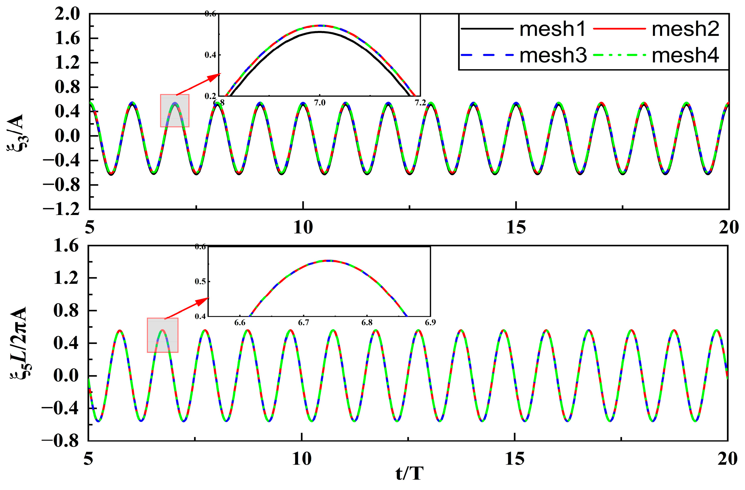
An appropriate number of grids and time step length can be obtained by comparing the heave and pitch motion of the structure at incident angle of 0°. Firstly, the FPSO is analyzed for grid convergence with a time step length of T/120, the incident amplitude of 1.8 m and the angular frequency of 0.56 rad/s. The following four meshing schemes have been applied in the FPSO model: mesh1 (1118), mesh2 (1400), mesh3 (1768), mesh4 (2026). Figure 2 shows the comparison of the dimensionless results of the FPSO for heaving motion and pitch motion with different number of grids. It can be found that there are differences in the heaving motion between the mesh1 and the other three meshing schemes, and the pitching motion of the four schemes is basically the same. Therefore, the mesh2 is more suitable for numerical simulation of FPSO due to the accuracy and efficiency of numerical calculations. In the diagram, A represents the incident amplitude; L is the length of an FPSO; ξ denotes the movement of an FPSO.
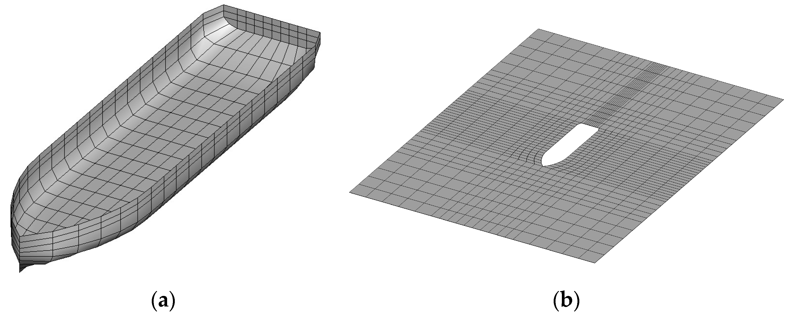
It is necessary to arrange the grid on the free water surface, as the Rankine source Green’s function is used in the model of this paper. The grid is divided as shown in Figure 3, 1050 high-order meshes are used for the free water surface, and 350 high−order meshes are used for the structure in this paper. The entire computational domain includes a free water surface area with a length of four times the ship length and a width of three times the ship length, as well as the body surface of the FPSO. To eliminate the reflection of the incident waves and ensure that the structure can be simulated stably for a long time, a damping layer needs to be placed in the area beyond 0.8 times the length of the ship.
Then, the FPSO was analyzed for time step convergence using the following four time step schemes: T/90, T/100, T/110, T/120. Figure 4 shows the comparison of the dimensionless results for the heave (a) and pitch (b) motions of the FPSO. From the graph, it can be seen that the calculation results of the four different time steps are basically the same in both heave and pitch motion. The numerical divergence occurs when using T/80 for numerical simulation, and the time step needs to meet the requirements for irregular wave simulation. Therefore, this model is more appropriate when using a time step of T/100 for numerical calculations.

3.3. Damping Matrix

Offshore structures do not always encounter following or heading waves at sea, but also encounter sea conditions with oblique wave. Rolling motion must be taken into account in oblique waves. The result of the potential flow theory is different from the actual motion due to the effect of viscosity. Therefore, it is necessary to add roll damping for correction in solving roll motion. The method of calculating roll damping by solving the critical damping is used in this article.
The critical damping during the roll motion of a rigid body can be expressed by Equation (27):
D c r i t i c a l = 2 ( I x x + Δ I x x ) K R o l l
where, I x x represents the moment of inertia of roll; Δ I x x denotes the added mass moment of inertia; K R o l l is the stiffness of the roll. The roll damping is generally recommended to be 5% to 10% of the critical damping. The roll damping of FPSO is 8% of the critical damping.

3.4. The Validation of Numerical Model

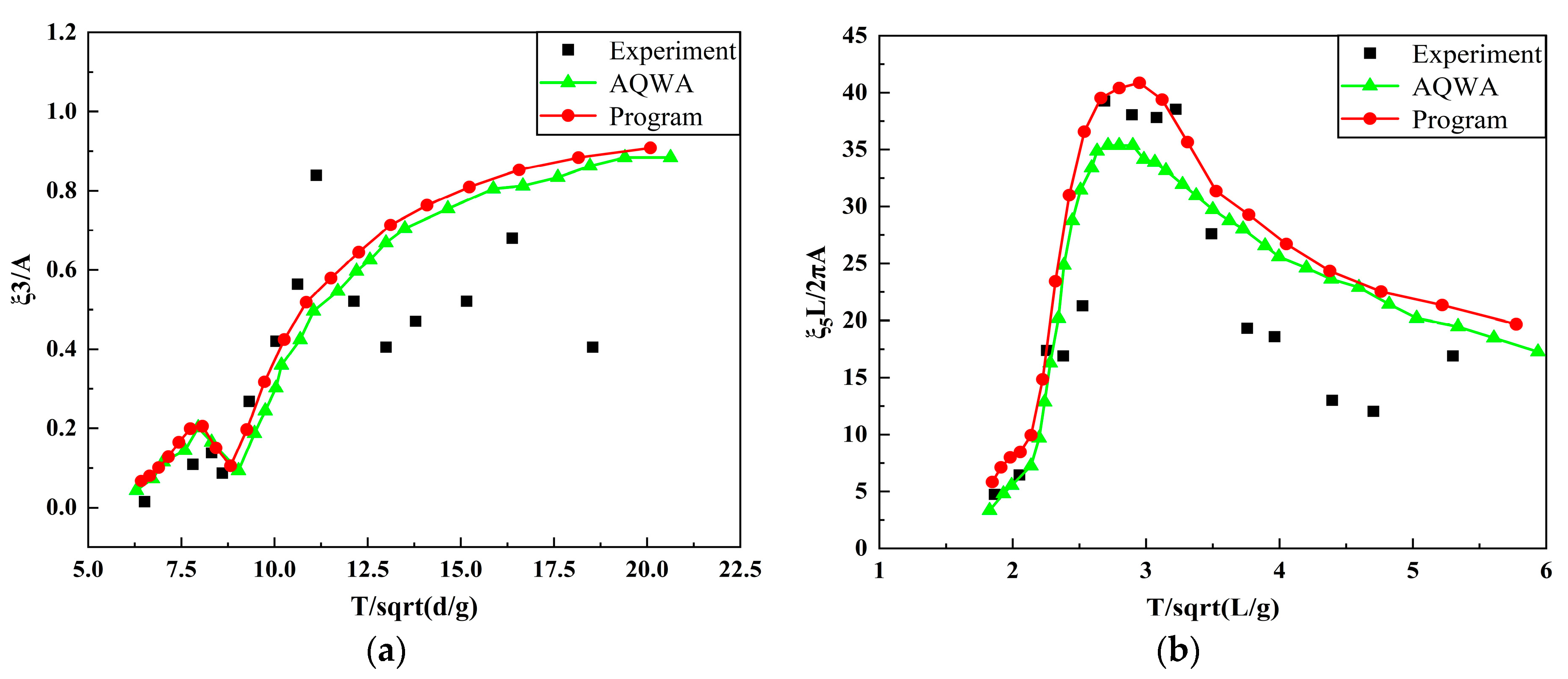
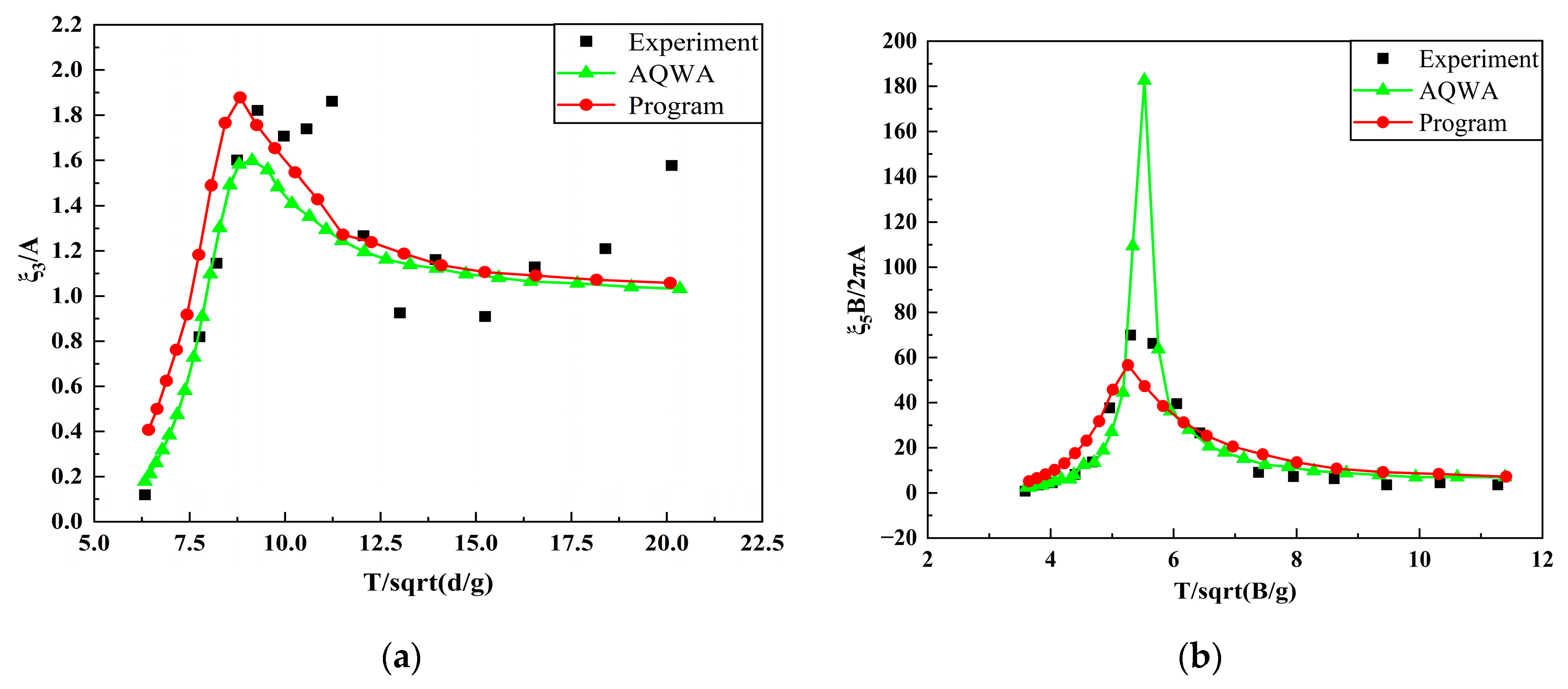
To verify the accuracy of the program used in this text for calculating FPSO models, the simulation results obtained from the program are subjected to nondimensionalization and compared to the results obtained from AQWA, a commercial hydrodynamic software, as well as experimental data. The simulated conditions adopted in this section are as follows: a fifth-order Stokes wave with incident angles of 0° and 90°; an incident wave amplitude of 1.8 m. The angular frequency is ranging from 0.33 to 1.02 rad/s, which was equally divided into 20 parts.
Figure 5 shows a comparison of the motion responses of FPSO under different wave frequencies with an incidence angle of 0°. The results indicate an overall increase in heave motion with a decrease in wave frequency. In the high-frequency interval, the heave motion results presented in this study are in general agreement with those obtained from AQWA and experimental data, whereas some discrepancies exist in the low-frequency range, but the basic trend is consistent. As for the pitch motion, it generally increases with a decrease in wave frequency, reaching its peak when it approaches the natural frequency of FPSO, in a phenomenon known as resonance, before decreasing again with a decrease in the wave frequency. The motion results of FPSO in paper are generally in agreement with those obtained from AQWA in the high-frequency and low-frequency ranges. However, in the resonance range, the motion results of FPSO in paper are closer to the experimental data, and the resonance frequency range is wider than that of AQWA. This underscores the superior applicability of the numerical model introduced in this study in addressing engineering problems.
Based on Figure 5, it can be observed that the experimental results are relatively stable in the high frequency region. However, fluctuations are observed in the low frequency region, which differ from the numerical results. This is because that the wavelength of the incident wave is longer in the low-frequency region, the results are influenced by the reflection of waves in a limited length experimental tank.
Figure 6 presents a comparison of the motion responses of FPSO at different wave frequencies with an incidence angle of 90°. It can be observed from the graph that the heave motion increases as the wave frequency decreases, reaching a peak and then decreasing with further decrease in wave frequency. The heave motion results in this study are largely consistent with the results of AQWA in the low-frequency range but show slight deviation in the high-frequency range. The heave motion results in this study are largely in agreement with experimental results at the peak. The roll motion increases as the wave frequency decreases and reaches a peak when it approaches the natural frequency of FPSO, followed by a decrease as the wave frequency decreases further. The roll results in this study are mostly consistent with experimental results. However, the computational results obtained from AQWA exhibit considerable discontinuity in the resonant frequency range, with significant peaks that deviate from actual results.

4. The Impact of Irregular Waves on FPSO under Different Wave Spectra

4.1. Simulation and Verification of Irregular Waves

4.1.1. Operating Conditions

This current chapter will utilize the FPSO model as previously introduced. Detailed principal dimensions and hydrodynamic parameters can be found in Table 1. To ensure consistency of operating conditions across three different spectral shapes and to ensure reliable data results, four- and five-level sea states will be selected for performing seakeeping calculations on the FPSO. The spectral peak frequency can be determined using the most likely spectral shape parameters in the Ochi-Hubble spectrum, with the expression outlined as follows:
H S 1 = 0.84 H S H S 2 = 0.54 H S ω m 1 = 0.70 e 0.046 H S ω m 2 = 1.15 e 0.039 H S λ 1 = 3.00 λ 2 = 1.54 e 0.062 H S
where, H S 1 and H S 2 denote the significant wave heights at low and high frequencies, respectively; ω m 1 and ω m 2 represent the spectral peak frequencies at low and high frequencies, respectively; and λ 1 and λ 2 are the control parameters of the spectral shape.
The spectral peak frequency of the ITTC two-parameters spectrum and the JONSWAP spectrum can be determined by the most probable spectral shape of the Ochi-Hubble spectrum at low frequencies. This approach ensures consistency in the input wave parameters across the three different spectral shapes, and the detailed operational conditions for each spectral shape are presented in Table 2. As the ship motion patterns are relatively similar for 0° and 180° incident directions, this chapter focuses on the study of main incident directions at 0°, 30°, 60° and 90°. For this chapter, the directional spreading function for short-crested irregular waves is obtained from the Stereo Wave Observation Project (SWOP).

4.1.2. Long-Crested Irregular Waves

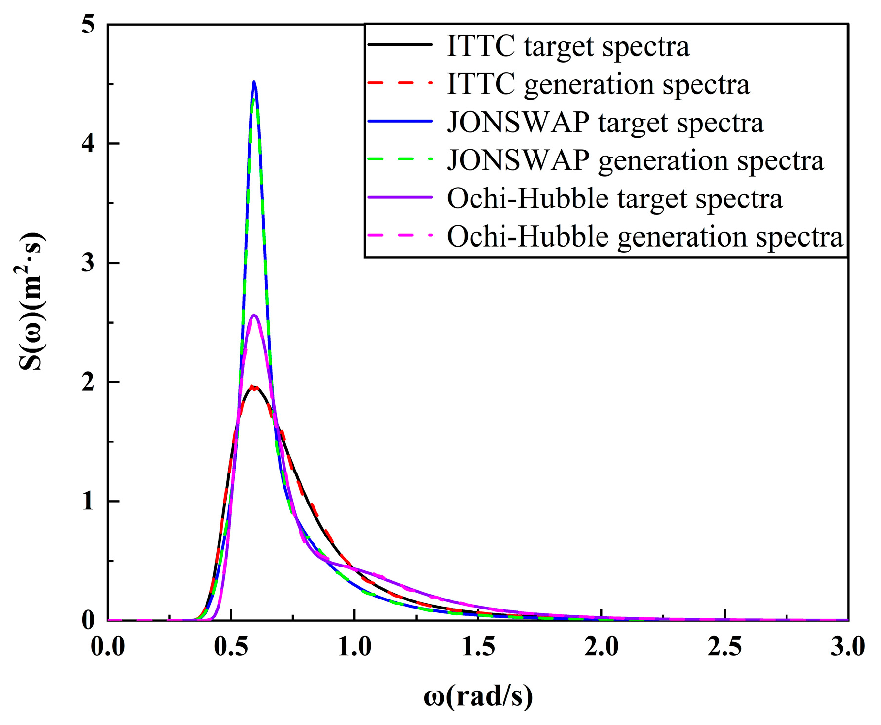
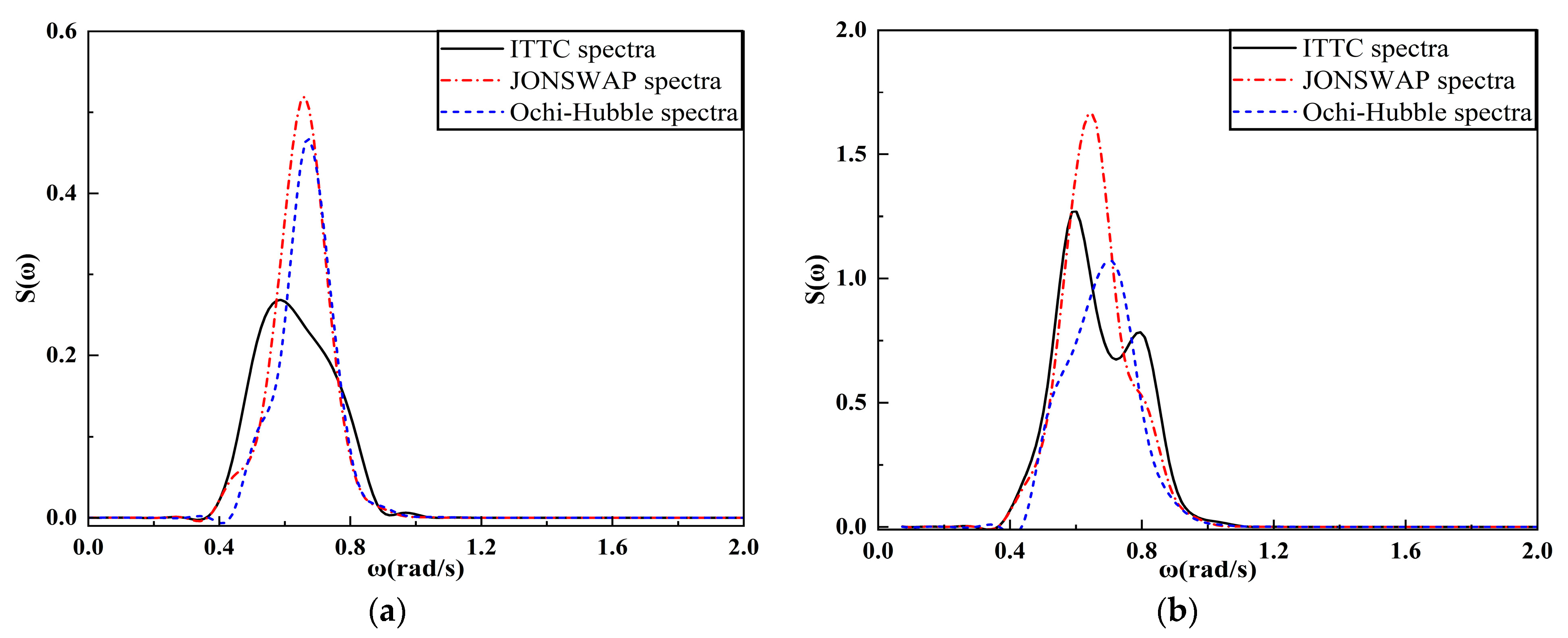
Based on the above class five sea state, a comparison is made between the target spectra and the generated spectra under 3.6 m long-crested irregular waves of different spectral shapes, as shown in Figure 7. The target spectra are obtained by inputting the spectral peak period and significant wave height into the formula for wave spectra, while the generated spectra are obtained by performing Fourier transformation of the wave surface time history at the free surface zero point. It can be observed from the figure that the computed spectra for the three spectral shapes are in close agreement with the target spectra, indicating that the simulation method used in this study can effectively simulate long-crested irregular waves under different spectral shapes.
From Figure 7, it is evident that among the three wave spectra under a significant wave height of 3.6 m, the JONSWAP spectrum exhibits the highest spectral density value of 4.6, followed by Ochi-Hubble spectrum with a value of 2.6, while the ITTC two-parameters spectrum has the lowest value of 1.9. Moreover, in comparison with the ITTC two-parameters spectrum and the JONSWAP spectrum, the Ochi-Hubble spectrum reveals an additional spectral peak at 1.2 rad/s, with a spectral density value of 0.4, in addition to the primary peak at 0.59 rad/s. Additionally, the spectral peak of JONSWAP spectrum is narrower than those of the other two spectra.

4.1.3. Short-Crested Irregular Waves

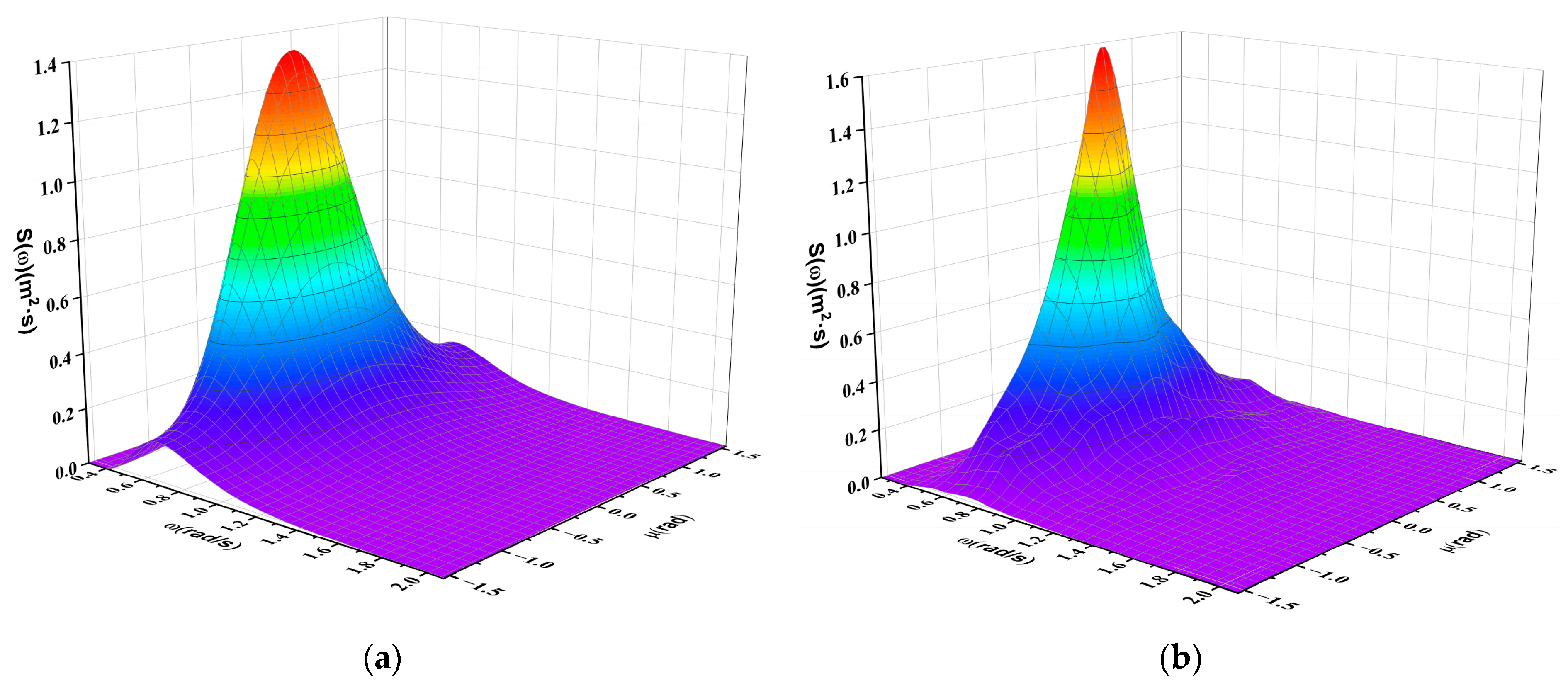
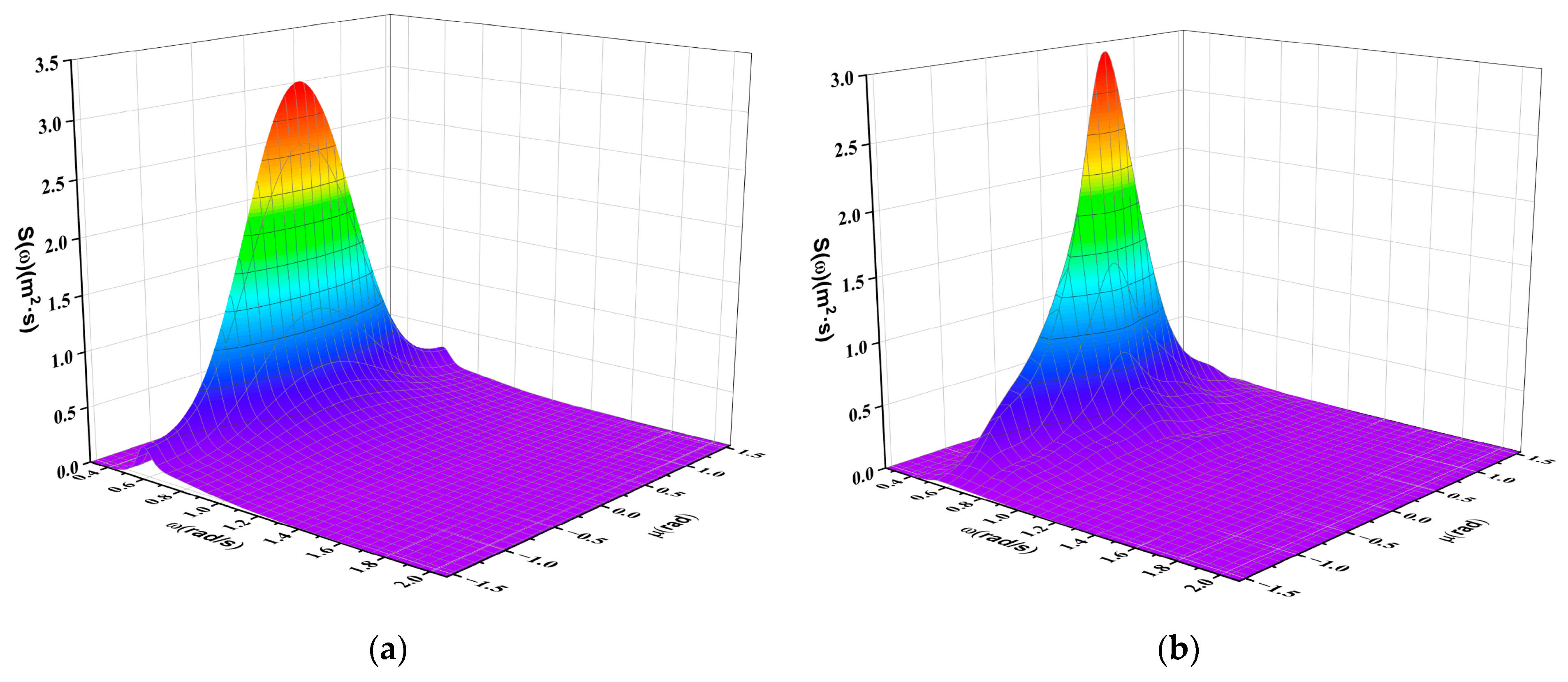
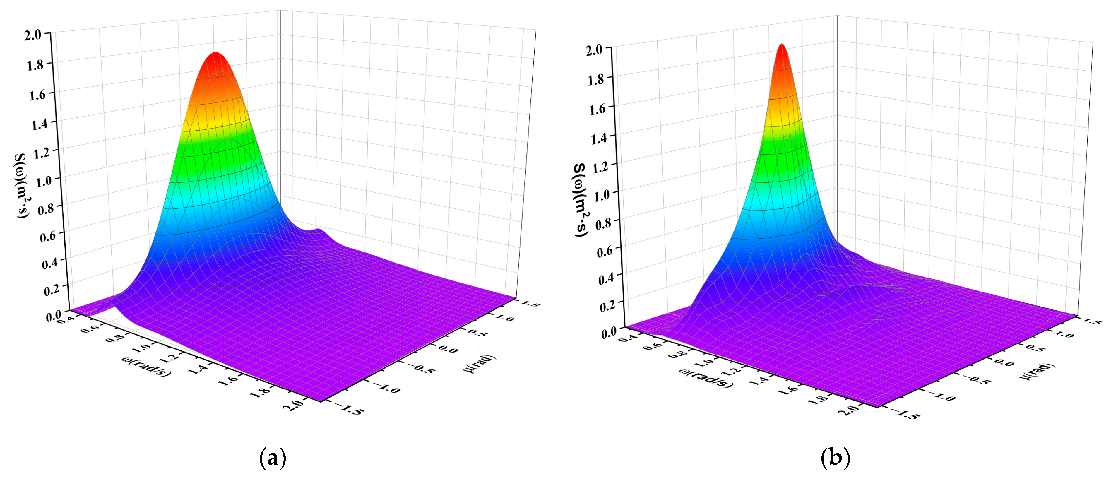
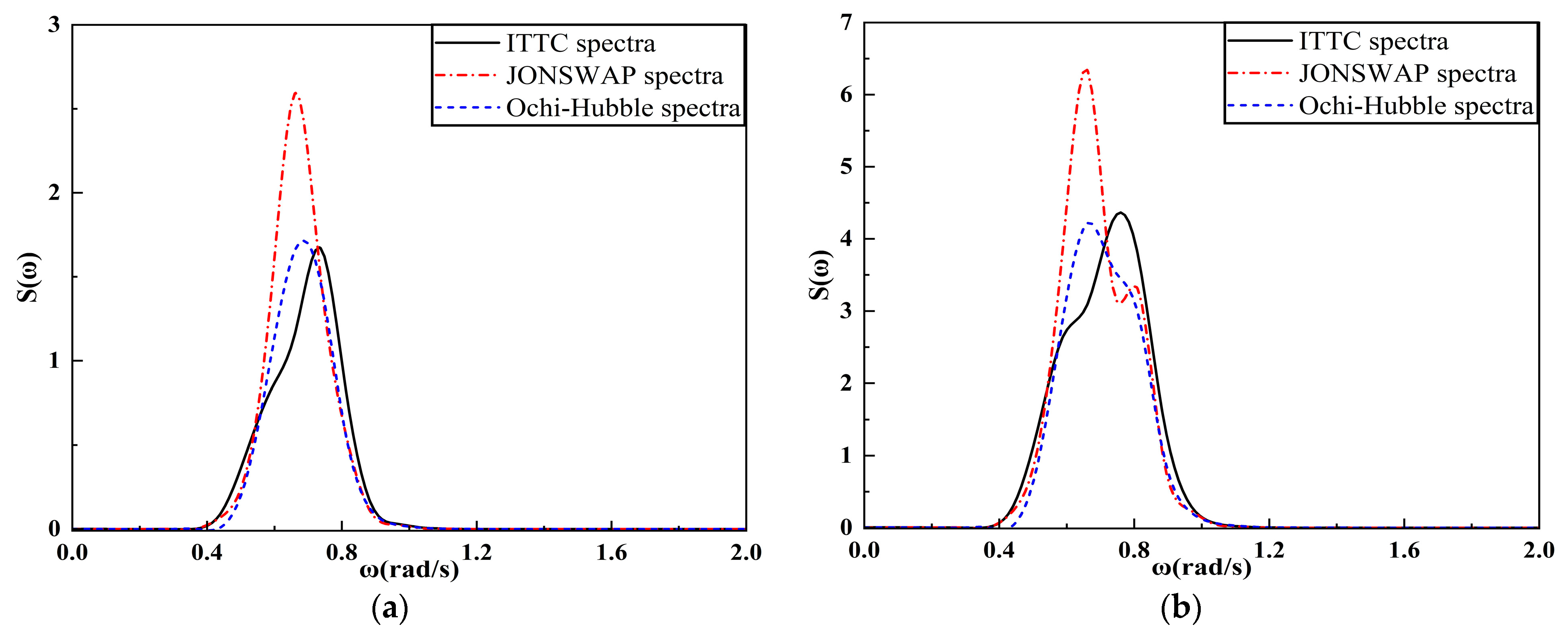
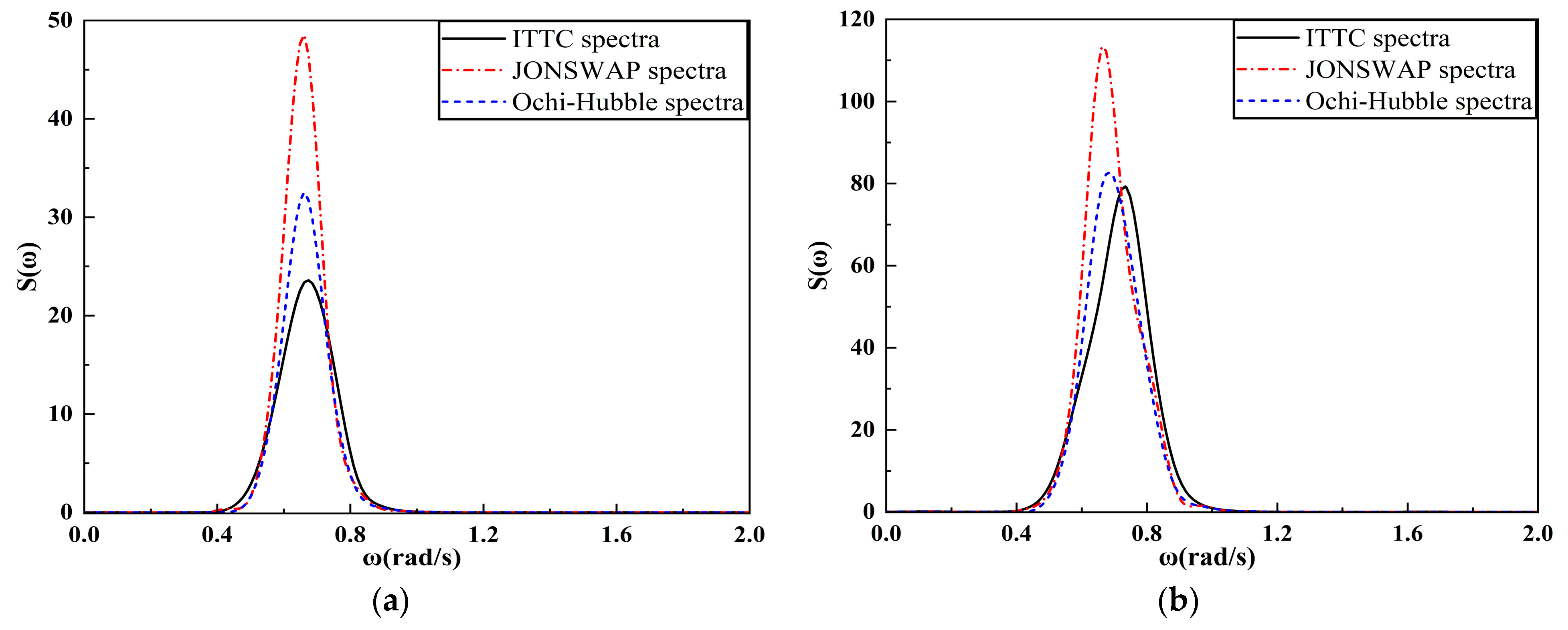
Based on the above class five sea state, the frequency domain correspondence method was used to simulate short-crested irregular waves on the free water surface under different wave spectra. The extended maximum entropy method was utilized to transform the wave time history of the free water surface into a three-dimensional spectral density image of short-crested waves. Figure 8, Figure 9 and Figure 10 provide a comparison of the target spectra and generated spectra under different wave spectra for short-crested irregular waves in five-level sea conditions. As can be seen from the figures, due to the energy distribution of short-crested waves in multiple directions, the spectral density value of short-crested waves is much smaller than that of long-crested waves. Under the same condition, similar to irregular long-crested waves, the spectral density peak value of the JONSWAP spectrum is much larger than that of the Ochi-Hubble spectrum and the ITTC spectrum.
From the figures, it can be observed that there are slight differences in the spectral density values of the ITTC target spectrum and the generated spectrum, which fall within an acceptable range. The target spectrum and generated spectrum of JONSWAP wave spectrum, as well as the target spectrum with the most probable spectral shape of Ochi-Hubble, exhibit similar spectral density with good agreement in directional and frequency distribution. This indicates that the short-crested wave simulation method used in this study has a great numerical simulation.
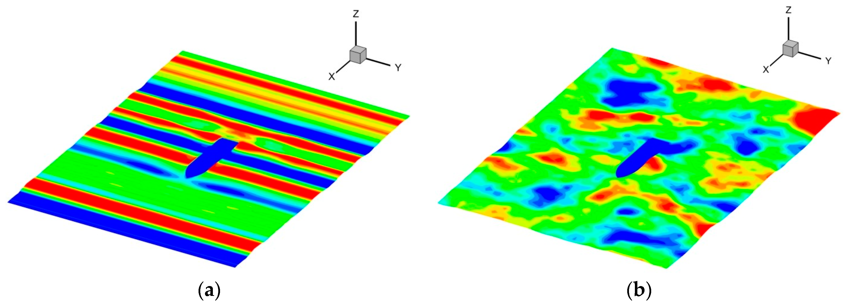
The flow field diagrams of long-crested irregular and short-crested irregular waves at the incident angle of 0° at a certain moment are presented in Figure 11. It is evident from the figure that the waveforms of long-crested irregular waves exhibit regular sinusoidal motion, with the wave peaks and troughs not being equidistant, but the wave surfaces at the same Y value are the same. On the other hand, the wave surfaces of short-crested irregular waves exhibit irregular and random variations, which are more similar to real ocean waves.

4.2. The Effect of Long-Crested Waves on FPSO under Different Wave Spectra

4.2.1. Analysis of the Time History of FPSO Motion Response

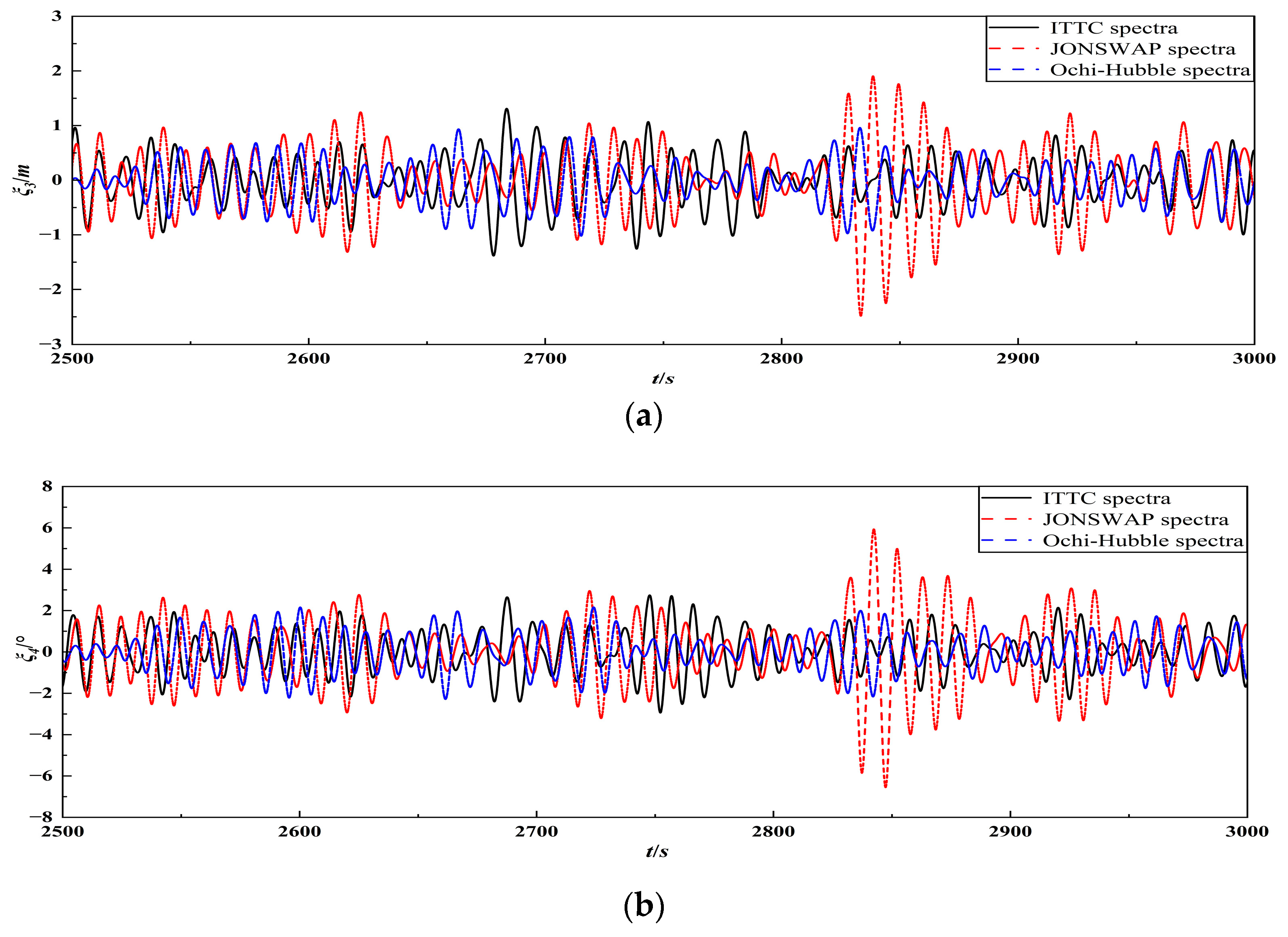
This section employs the frequency division method described in the previous section to simulate the effects of long-crested irregular waves under different wave spectra on FPSO, and the simulation time is 4000 s. Figure 12 presents the time history curves of the ship motion response under three wave spectra at the incident angle of 30° in level 5 sea state, showing the motion process from 2500 s to 3000 s. It can be observed from the figure that the amplitude, period, and phase of FPSO’s motion histories are not the same under long-crested irregular waves of different wave spectra.

4.2.2. Analysis of the Frequency Spectrum of FPSO Motion Response

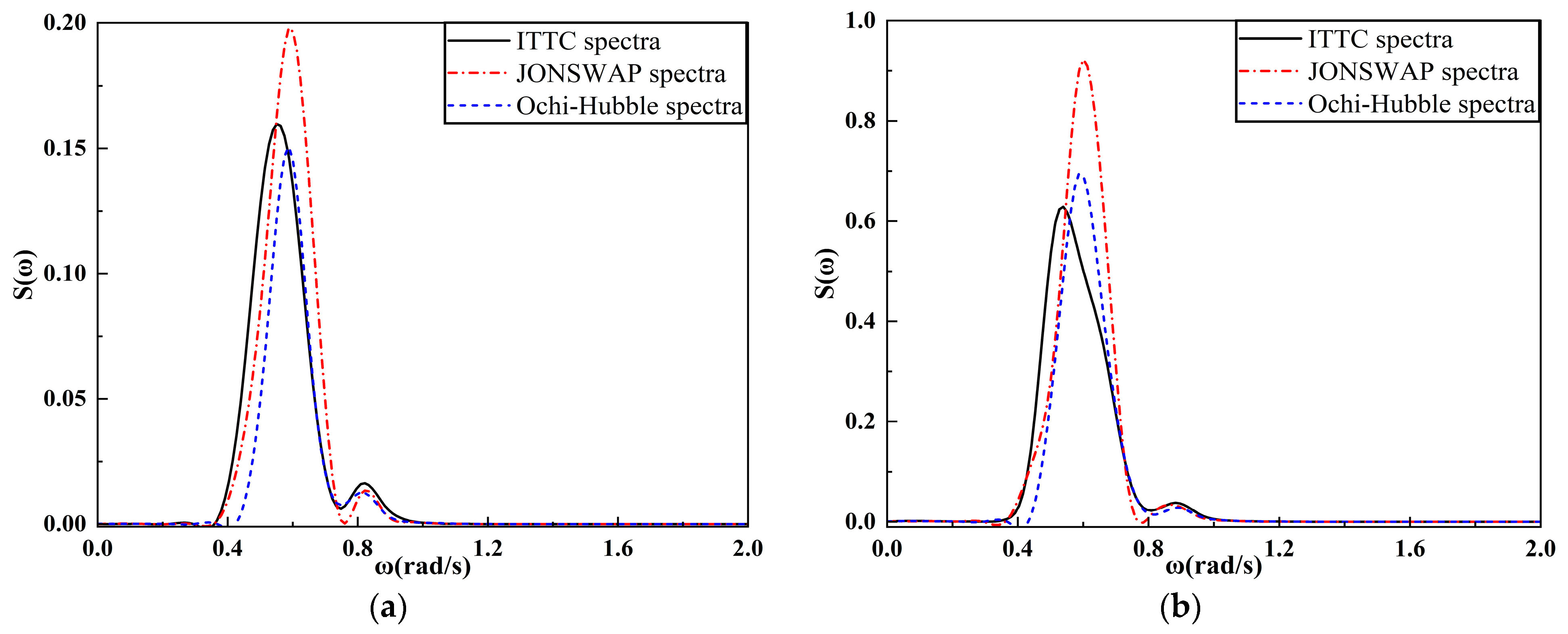
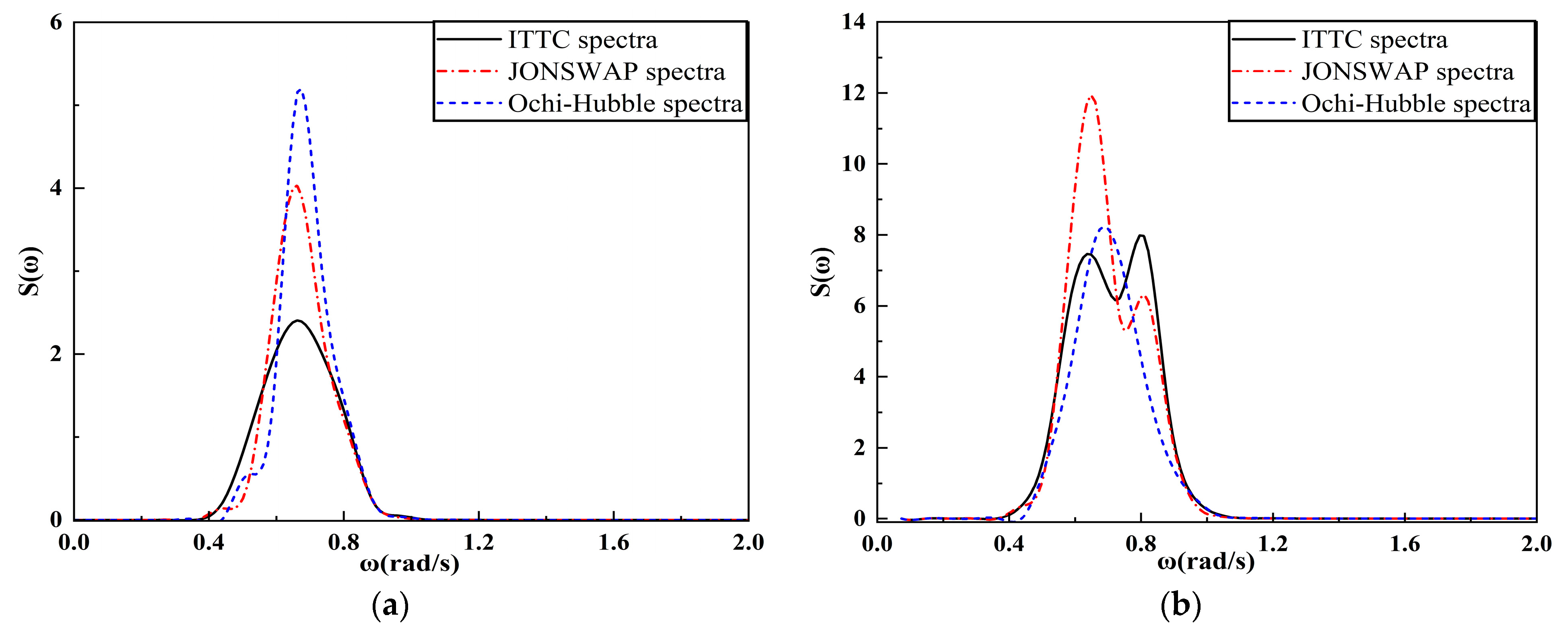
Figure 13 and Figure 14 present the spectral results of the heave and pitch motions of the FPSO subjected to long-crested irregular waves with incident angle of 0° in two different sea states. It can be observed that the spectral peak frequencies of the heave motion are quite similar among the three wave spectra. However, the peak frequency of the heave motion spectrum under the ITTC two-parameters spectrum is farther away from the incident wave peak frequency than that under the other two wave spectra. The peak frequency of the pitch motion spectrum is close to the incident wave peak frequency under sea condition 4, and the peak frequency of the pitch motion spectrum is between the incident wave peak frequency and the natural frequency of the ship under sea condition 5.
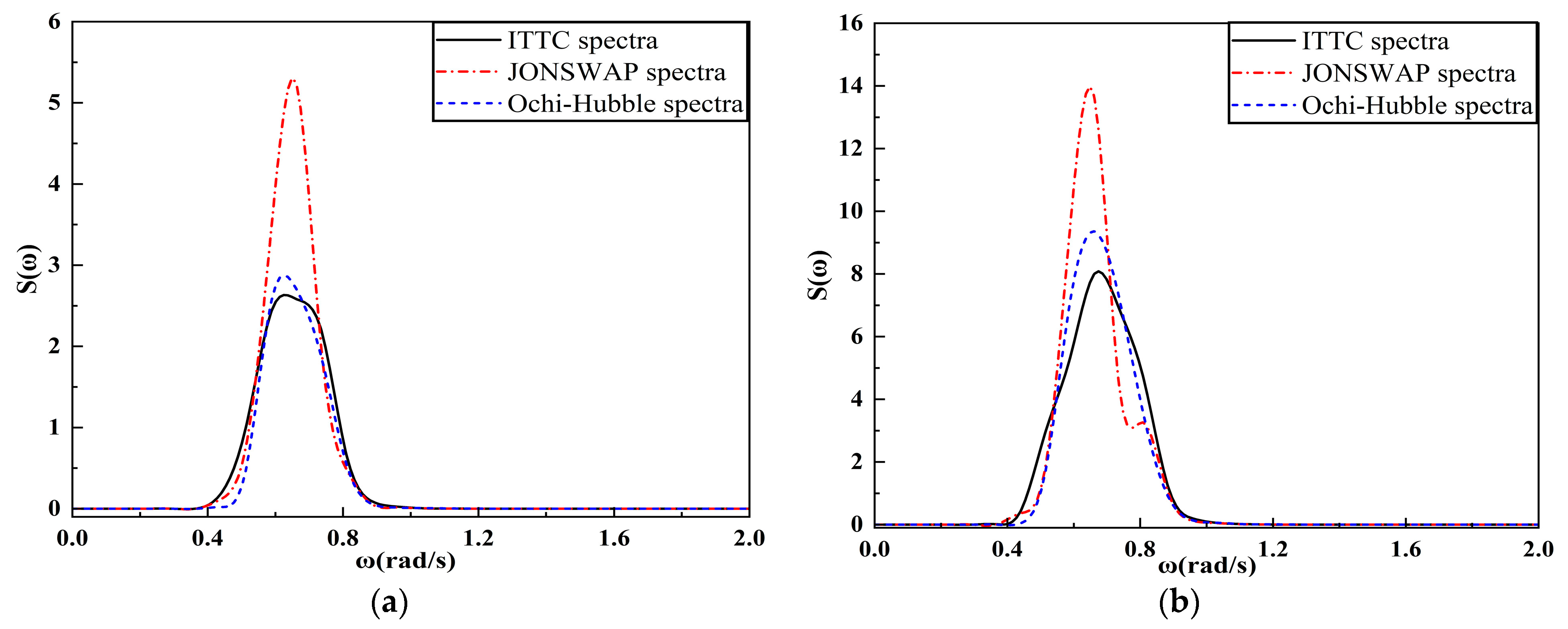
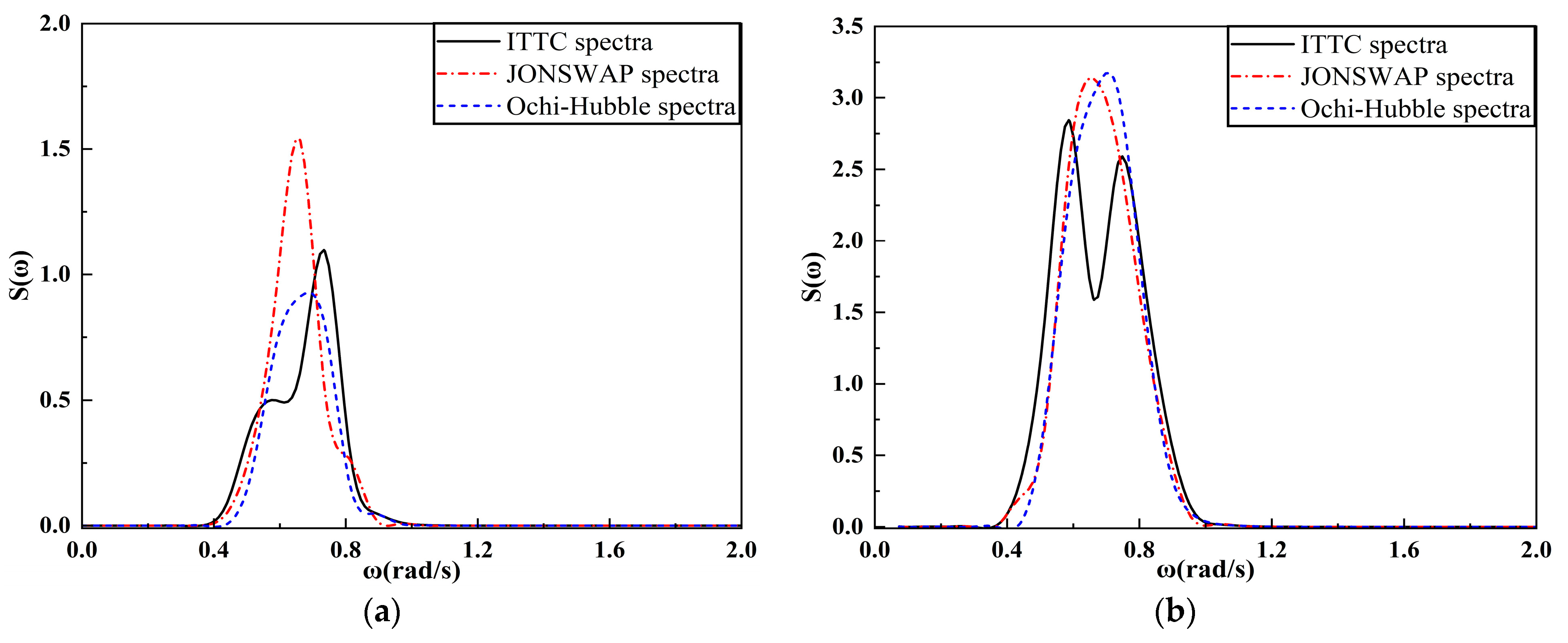
Figure 15 and Figure 16 present the spectral results of the heave and roll motion of FPSO under long-crested irregular waves with incident angle of 90° for two different sea states. It is observed that the peak frequencies of the heave motion spectra of FPSO are quite similar among the three different wave spectra. The peak frequency of the heave motion spectrum under the ITTC two-parameters spectrum is farther away from the incident wave peak frequency compared to the other two spectra. The spectral peak frequencies of the roll motion of FPSO are located near the roll natural frequency of the vessel under the three wave spectra and are basically the same under sea state four. However, the peak frequency of the motion spectrum under the ITTC two-parameters spectrum is further away from the ship’s natural frequency compared to the other two wave spectra under sea state five.

4.2.3. Analysis of the Significant Value of FPSO Motion Response

Statistical analysis was performed on the historical data of the FPSO’s motion in long-crested irregular waves, resulting in significant values for the motion in different directions. Comparison of the significant values of heave and roll motion of FPSO under three different wave spectra for various incident angles is presented in Figure 17 and Figure 18 for sea states four and five, respectively. Under two sea conditions, the analysis of the graphical data reveals that there is little difference in the significant values of the FPSO’s heave and roll in the three different wave spectra. The heave and roll motions of FPSOs under JONSWAP wave spectrum are slightly larger in the significant values than those obtained under ITTC two-parameters and Ochi-Hubble wave spectra. This is due to the selection of Ochi-Hubble wave spectrum which has the most probable wave shape and whose spectral area is similar to that of ITTC two-parameters wave spectrum. Between 0° and 90°, the significant amplitudes of heave and roll motions increase gradually with increasing angle for all three wave spectra. As the incident angle increases, the difference in significant amplitudes of heave and roll motions between JONSWAP wave spectrum and the other two wave spectra increases and reaches a maximum at an incident angle of 90°.
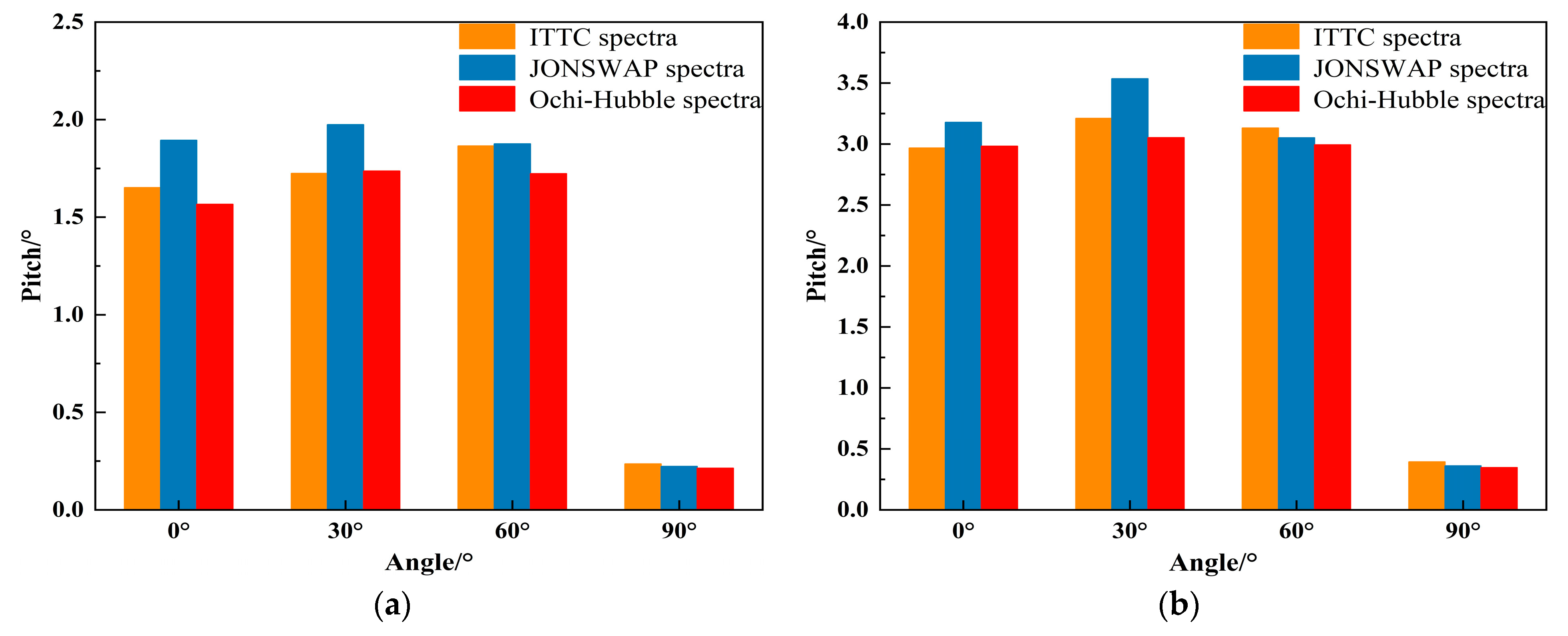
Figure 19 shows the comparison of the significant values of the pitch motion of FPSO under three different wave spectra at different incident angles. From the graph, it can be observed that under two types of wave conditions, the significant value of FPSO’s pitch motion in JONSWAP wave spectrum is slightly larger than that in ITTC two-parameters and Ochi-Hubble wave spectra at incident angles of 0° and 30°. At incident angles of 60° and 90°, the significant values of the pitch motion under the three wave spectra are equivalent. With the increase in the incident angle, the significant values of the pitch motion under the three wave spectra show a trend of first increasing and then decreasing, reaching a peak at the incident angle of 30°. It can be seen that the significant values of the pitch motion under the three wave spectra are smaller at the incident angle of 90°. This is because long-crested irregular waves are unidirectional waves and almost have no effect on the pitch motion of the structure at this incident angle.
From Figure 18 and Figure 19, it can be observed that, at the same incident angle, the roll motion difference between the JONSWAP wave spectrum and the other two wave spectra is greater than the difference in pitch motion. This indicates that the JONSWAP spectrum has a greater impact on roll motion than on pitch motion of the FPSO among the selected wave spectra in this study.

4.2.4. Analysis of the Range of FPSO Motion Response

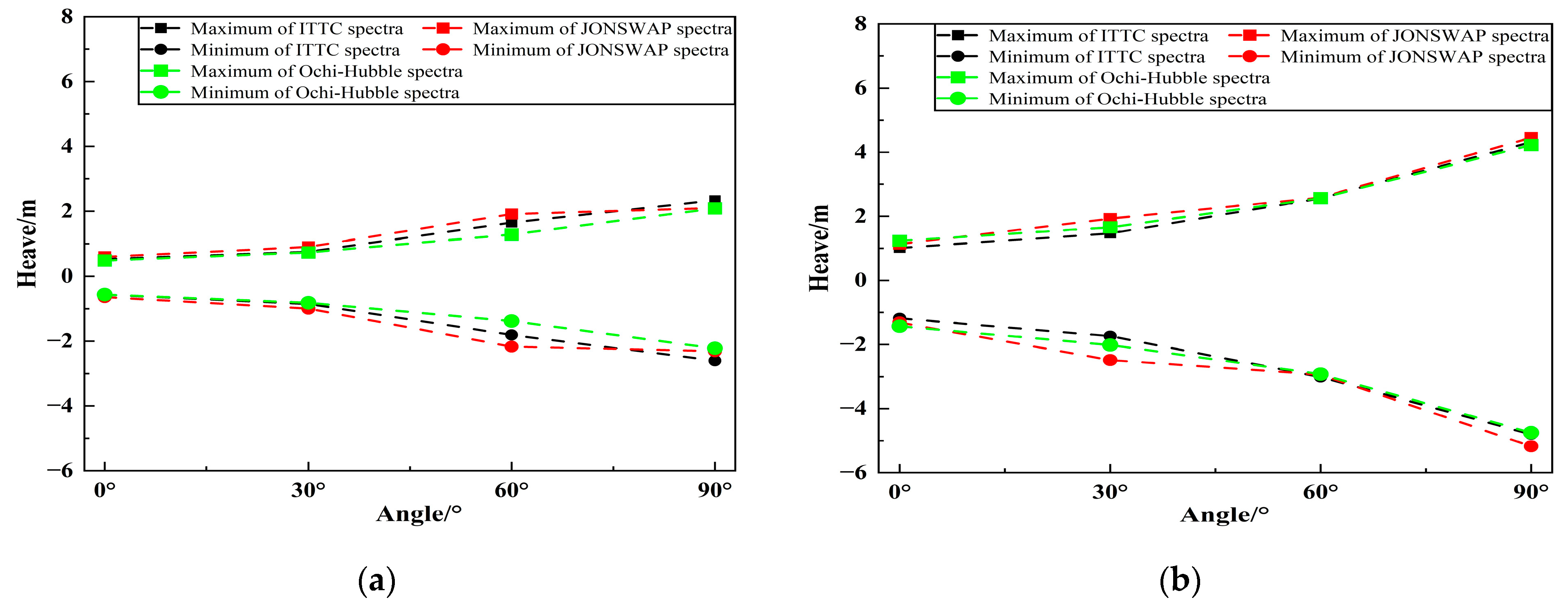
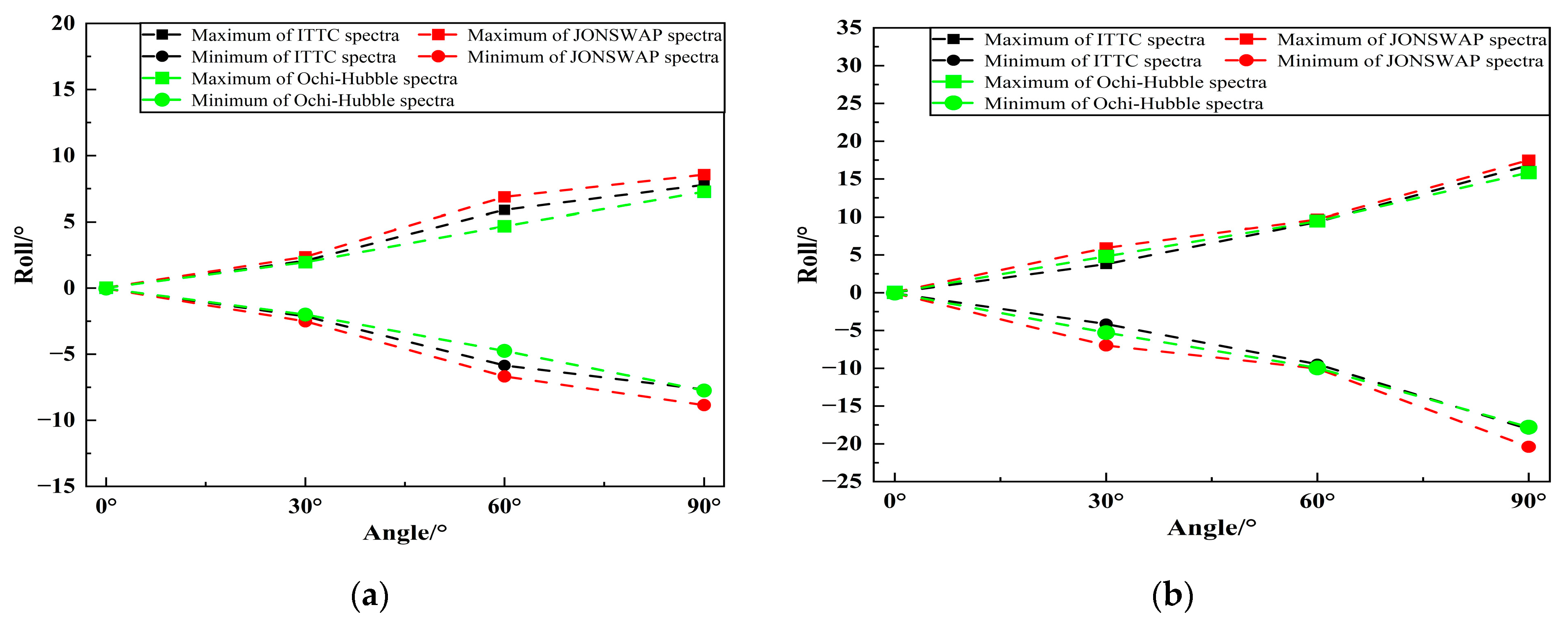
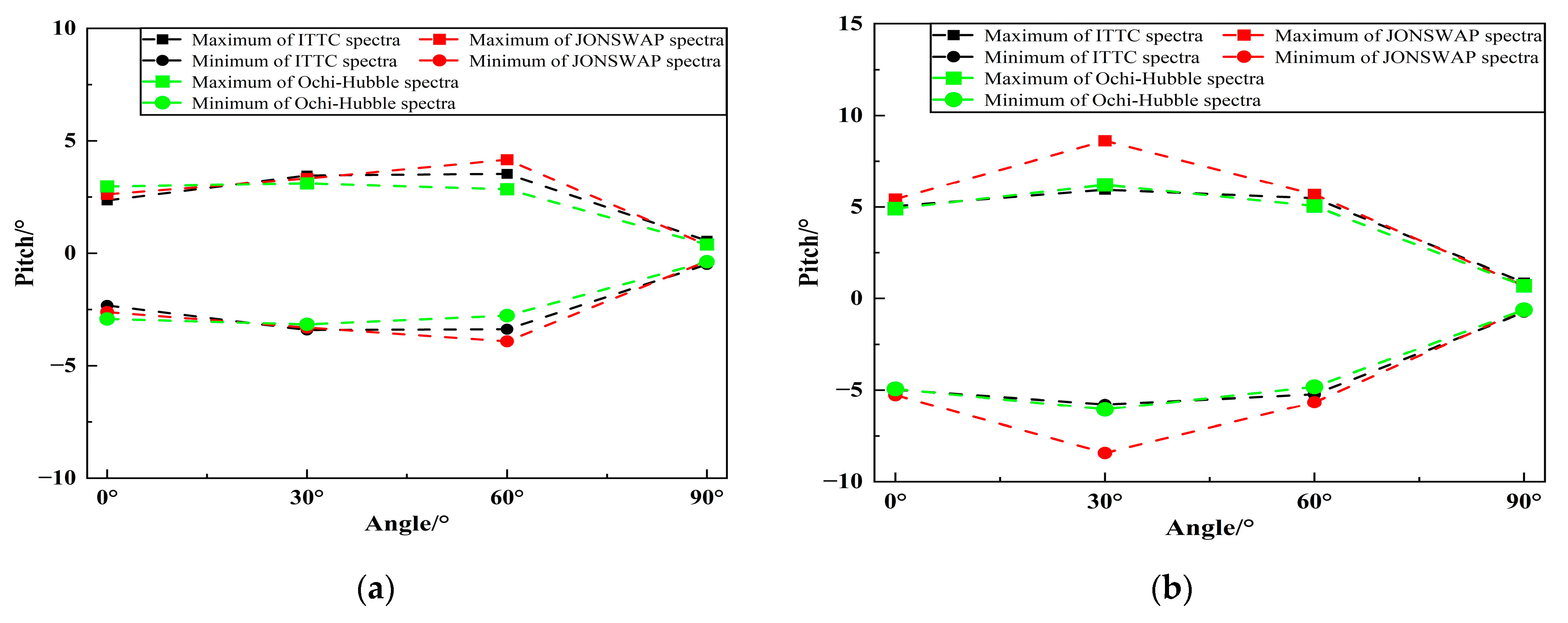
Through statistical analysis of the simulated FPSO motion history, the impact of different wave spectra under irregular long-crest waves at various incident angles on the range of the vessel’s motion were obtained, as shown in Figure 20, Figure 21 and Figure 22. Figure 20 and Figure 21, respectively, show the range of FPSO’s heave and roll motion under different wave spectra in two sea conditions. It can be seen from the figures that the range of FPSO’s heave and roll motion under the three wave spectra gradually increases with the increase of the incident angle from 0° to 90°. Under sea state four, when the incident angle is 0° and 30°, the range of heave motion of FPSO is basically the same for the three wave spectra; the range of heave motion for FPSO is the largest under JONSWAP wave spectrum, followed by ITTC two-parameters wave spectrum, and the smallest under Ochi-Hubble wave spectrum when the incident angle is 60°; when the incident angle is 90°, the range of heave motion of FPSO is the largest under ITTC two-parameters wave spectrum, and the range of roll motion of FPSO is the largest under JONSWAP wave spectrum. At sea state five, when the incident angles are 0° and 60°, the heave motion range of FPSO is basically the same under three wave spectra; when the incident angle is 30°, the heave and roll motion range of FPSO is the largest under JONSWAP wave spectrum, followed by Ochi-Hubble wave spectrum, and the smallest under ITTC two-parameters wave spectrum; when the incident angle is 90°, the heave and roll motion range of FPSO is the largest under JONSWAP wave spectrum, and basically the same under Ochi-Hubble and ITTC two-parameters wave spectra.
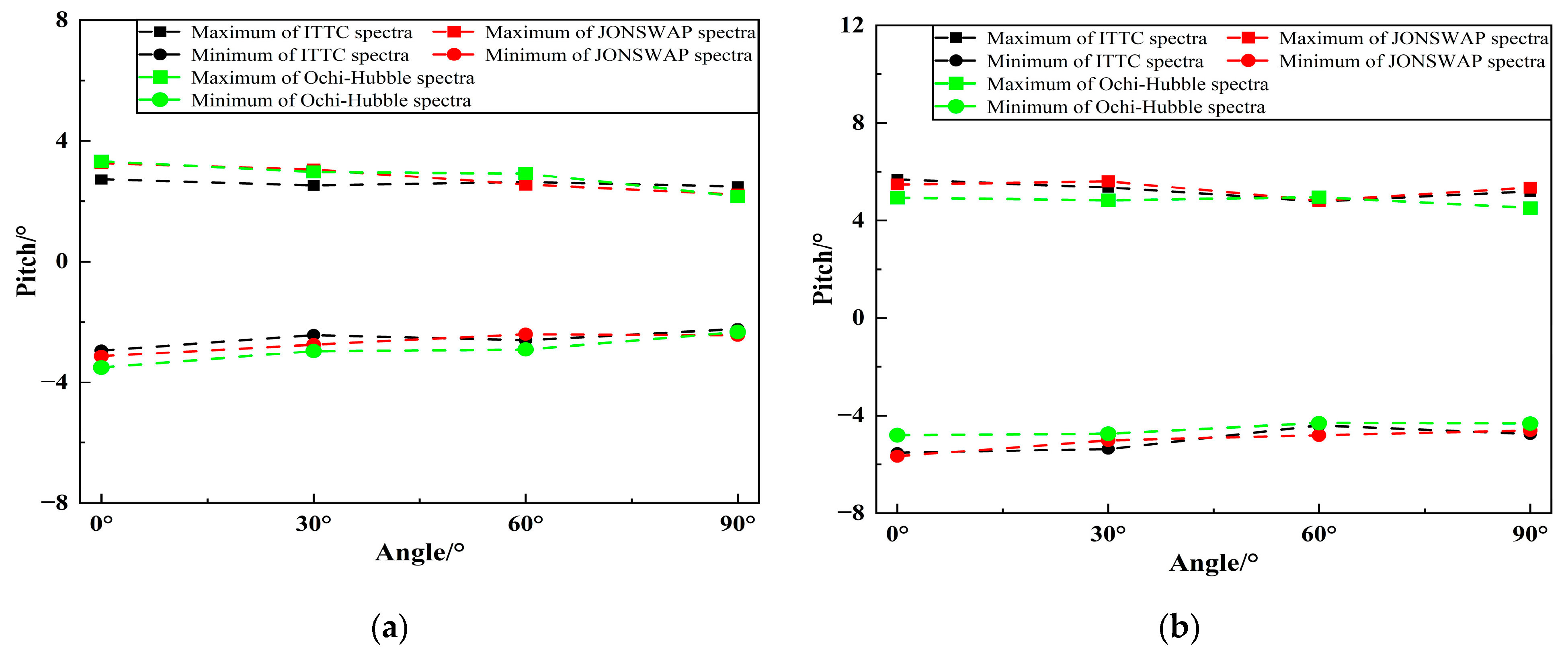
Figure 22 shows the range of pitch motion of FPSO under different wave spectra in two sea conditions. As can be seen from the graph, under the two sea conditions, as the incident angle increases from 0° to 90°, the pitch motion under the three wave spectra first increases and then decreases. In the fourth sea condition, the peak value is reached at an incident angle of 60°, while in the fifth sea condition, the peak value is reached at an incident angle of 30°. Under the fourth sea condition, at incident angles of 0°, 30° and 90°, the pitch motion range of FPSO is basically the same under the three wave spectra; at an incident angle of 60°, the pitch motion range of FPSO under JONSWAP wave spectrum is slightly larger than that under ITTC two-parameters wave spectrum, and the smallest under Ochi-Hubble wave spectrum. Under the fifth sea condition, at incident angles of 0°, 60°, and 90°, the pitch motion range of FPSO is basically the same under the three wave spectra; at an incident angle of 30°, the pitch motion range of FPSO under JONSWAP wave spectrum is larger than that under the other two wave spectra, with a difference in motion amplitude of about 6°.

4.3. The Effect of Short-Crested Waves on FPSO under Different Wave Spectra

4.3.1. Analysis of the Time History of FPSO Motion Response

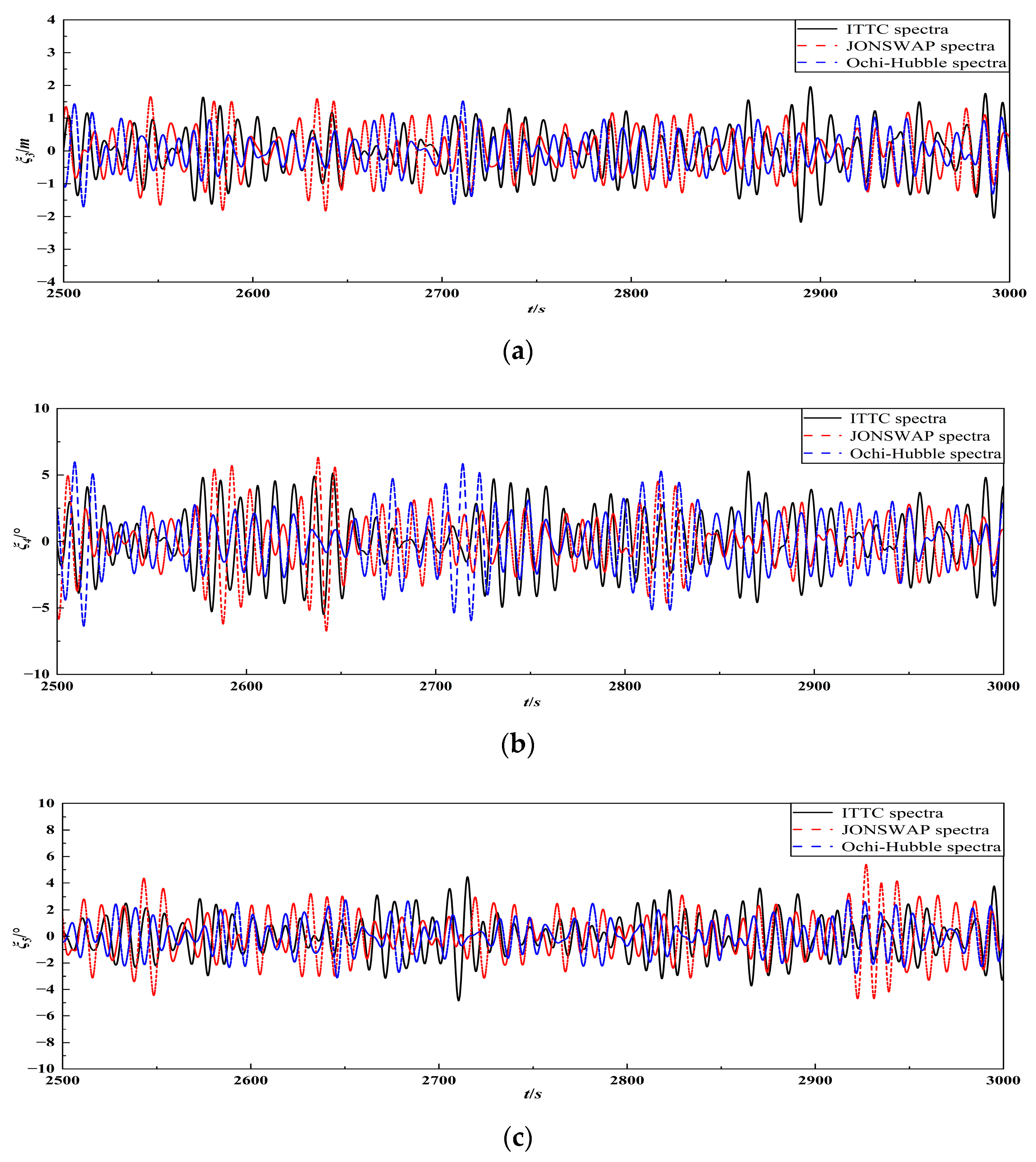
According to the hydrodynamic calculation program developed based on the wave–body interaction and irregular short-crested wave theory, the effects of short-crested irregular waves on FPSO models are simulated under different wave spectra. The simulation time is 4000 s, and the motion history of the FPSO model under the action of irregular short-crested waves was obtained. Figure 23 shows the motion history of FPSO under different wave spectra of the short-crested irregular waves in the incident angle of 30° in five-level sea conditions during 2500 s–3000 s.

4.3.2. Analysis of the Frequency Spectrum of FPSO Motion Response

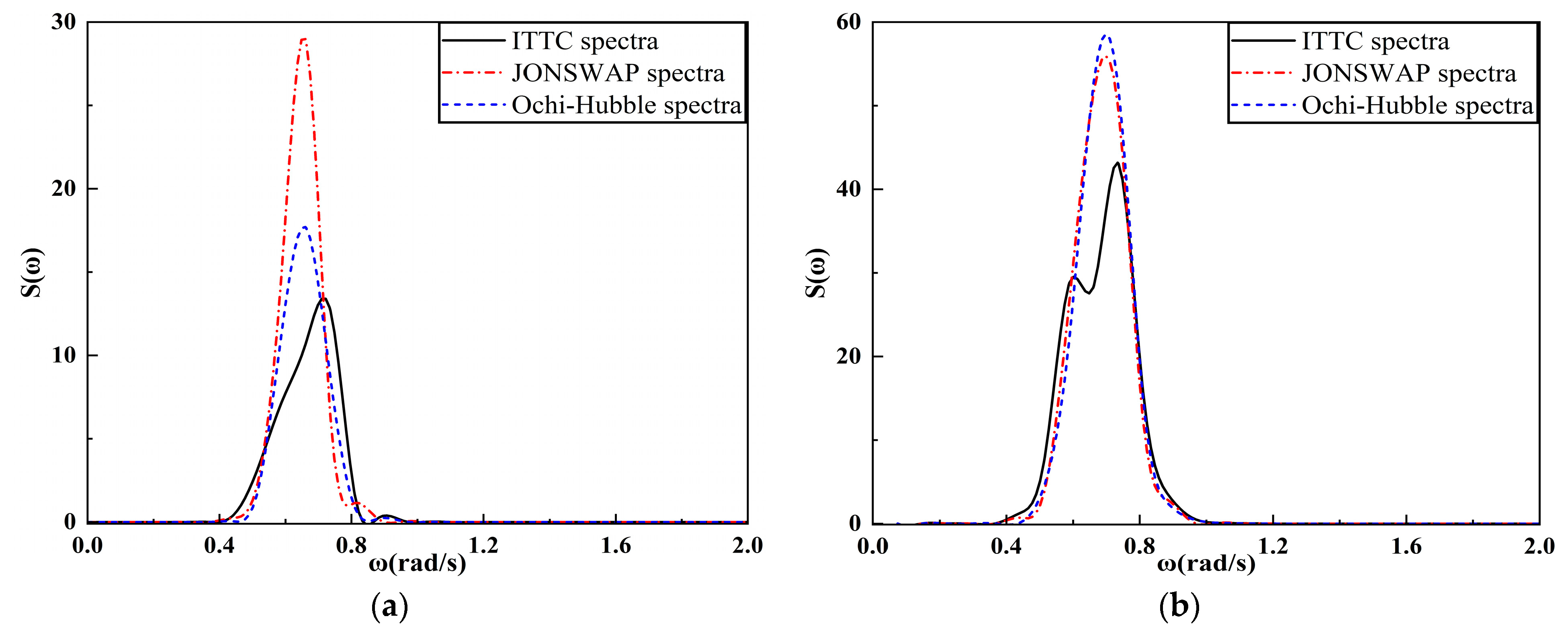
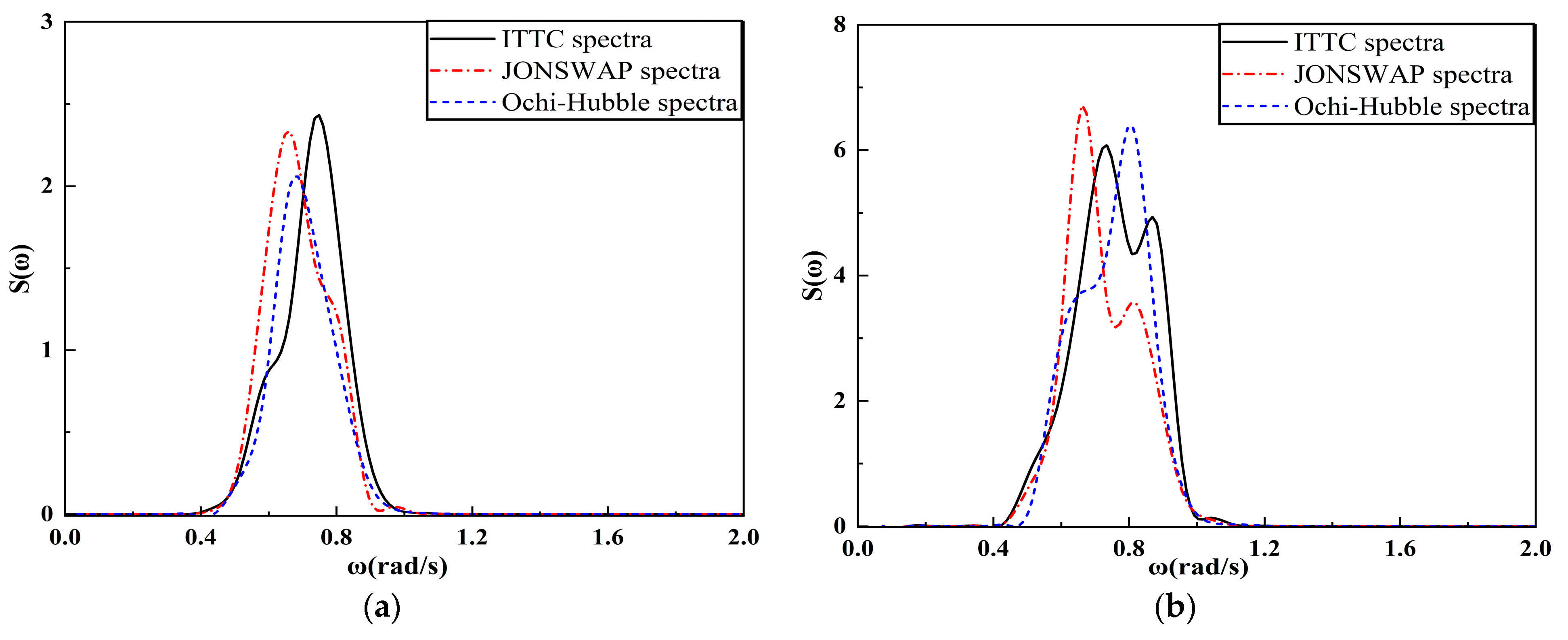
Figure 24, Figure 25 and Figure 26, respectively, show the spectral results of heave, roll and pitch motions of FPSO under short-crested irregular waves with the incident angle of 0° in two sea conditions. It can be seen that the peak frequency of heave motion spectrum of FPSO in four-level sea state under ITTC two-parameters spectrum is farther away from the incident wave peak frequency than that under the other two wave spectra with the incident angle of 0°. The peak frequency of heave motion spectrum of FPSO in the most probable spectrum form of Ochi-Hubble under five-level sea state is farther away from the peak frequency of the incident wave than that under the other two wave spectra. Moreover, the heave motion spectrum under ITTC two-parameters spectrum in five-level sea state presents a double peak, with the main peak located near the incident wave peak frequency. The peak frequency of roll motion spectrum in the three wave spectra under two sea conditions is basically the same, located near the incident wave peak frequency and the ship’s roll natural frequency, respectively. The peak frequency of the pitch motion spectrum in the three wave spectra under sea state four is basically the same, located near the incident wave spectrum peak frequency. Under sea state five, the pitch motion spectrum under the ITTC two-parameters spectrum and the JONSWAP spectrum presents a bimodal distribution, located near the ship’s pitch natural frequency.
Figure 27, Figure 28 and Figure 29, respectively, present the spectral results of the heave, roll and pitch motions of an FPSO subjected to the short-crested irregular waves with an incident angle of 90° under two types of sea states. It can be observed that the spectral peak frequency of the heave motion of the FPSO under the ITTC two-parameters spectrum in a four-level sea state is farther away from the spectral peak frequency of the incident wave than that of the heave motion under the other two wave spectra for the incident angle of 90°. Under the fifth-order sea state, the spectral peak frequency of heave motion in Ochi-Hubble spectrum is more far away from the spectral peak frequency of incident wave than that in the other two wave spectra. In addition, the heave motion spectrum under ITTC two-parameters spectrum presents a bimodal distribution, with the main peak located near the spectral peak frequency of incident wave. The rolling motion spectra of three types of waves in four-level sea state are located near the spectral peak frequency of incident wave. The roll motion spectrum under the ITTC two-parameters spectrum exhibits a bimodal distribution, with the main peak located near the spectral peak frequency of incident wave and the secondary peak located near the natural frequency of the ship’s roll. The roll spectra under the other two different wave spectra also exhibit peaks near the natural frequency of the vessel’s roll motion. Under sea state four, the peak frequency of the pitching motion spectrum among three wave spectra is located near the frequency of the incident wave spectrum and the natural frequency of the ship’s pitch. Under sea state five, the pitching motion spectrum of the ship in both ITTC two-parameters and JONSWAP spectra displays a double peak structure, with the main peak located near the natural frequency of the ship’s roll.

4.3.3. Analysis of the Significant Value of FPSO Motion Response

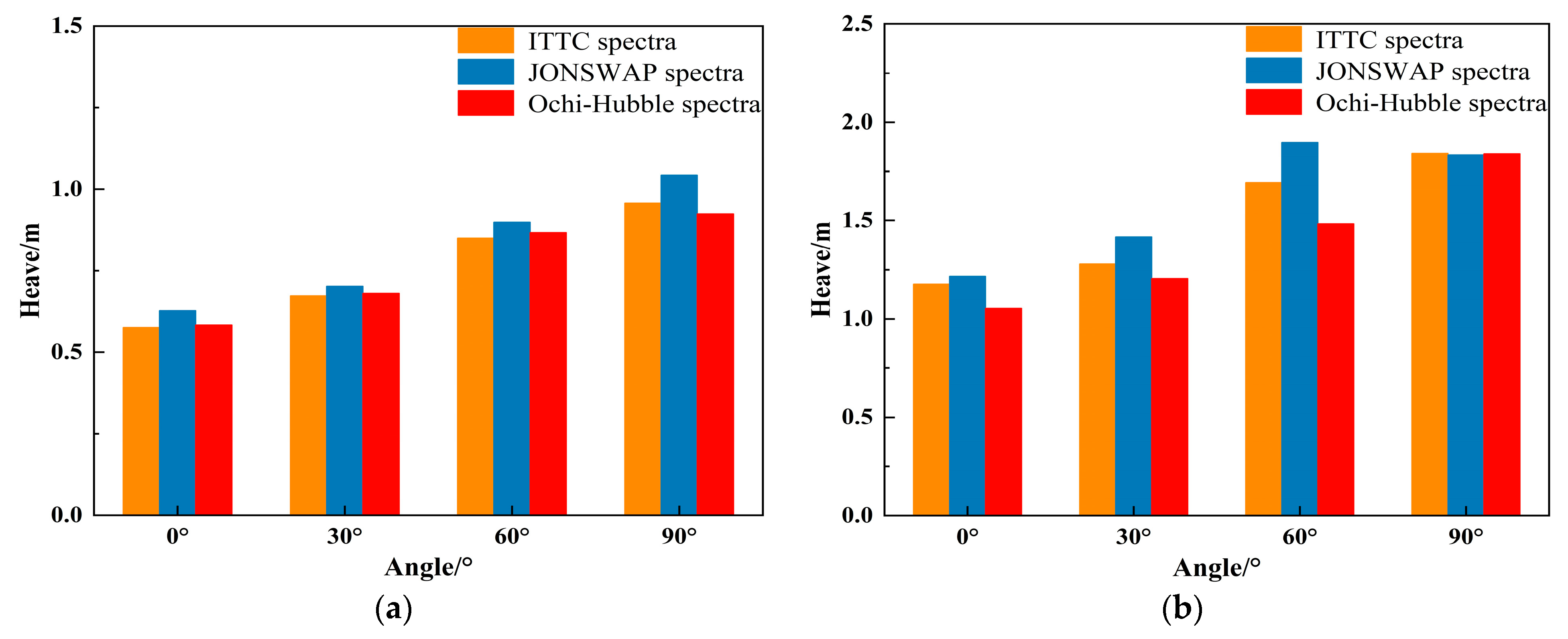
Through statistical analysis of the motion history of FPSO under the action of the short-crested irregular waves, the significant values of ship motion under different wave spectra are obtained. Figure 30 shows the comparison of significant values of heave motion of FPSO under three wave spectra at different incident angles. It can be seen from the figure that under both sea conditions, as the incident angle increases from 0° to 90°, the significant values of heave motion under the three wave spectra gradually increase. However, under sea condition level five, the significant values of FPSO’s heave motion under JONSWAP spectrum at incident angle of 60° is greater than that at incident angle of 90°. Under the fourth-level sea condition, the significant values of FPSO’s heave motions are basically similar at the incident angles of 0°, 30°, and 60° under the three wave spectra, while at the incident angle of 90°, the significant values of FPSO’s heave motions under the JONSWAP spectrum are the largest, and those under the other two wave spectra are basically similar. Under the fifth-level sea condition, the significant values of FPSO’s heave motions are basically similar at the incident angles of 0° and 90° under the three wave spectra, while at the incident angles of 30° and 60°, the significant values of FPSO’s heave motion under the JONSWAP spectrum is the largest, and that under the Ochi-Hubble spectrum is the smallest. At the incident angle of 60°, the difference in the significant values of FPSO’s heave motions between the two spectra is the largest, which is 0.41 m.
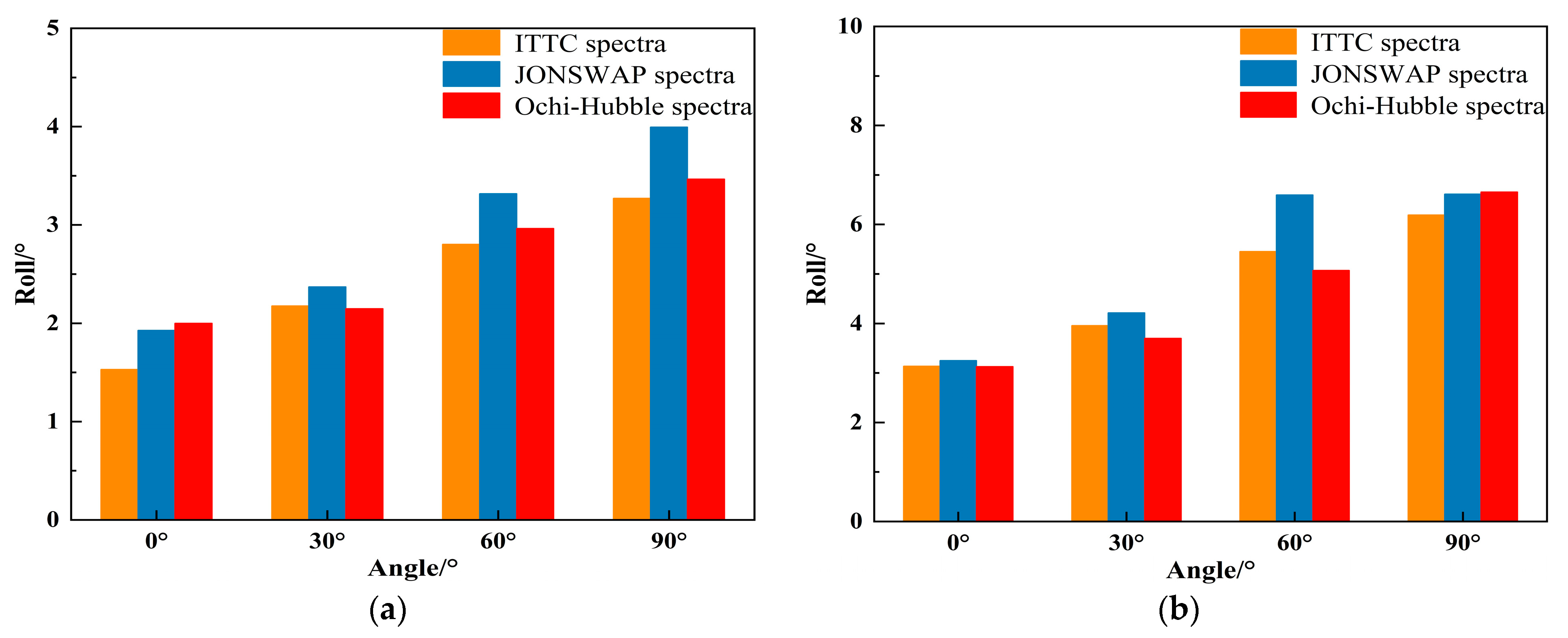
Figure 31 shows the comparison of the significant values of the FPSO’s roll motion under three different wave spectra at different incident angle. As can be seen from the figure, as the incident angle increases from 0° to 90°, the significant values of the roll motion under the three wave spectra gradually increase for both sea conditions. Under sea condition level four, the roll motion of FPSO under ITTC two-parameters spectrum has the minimum significant value when the incident angle is 0°, while the roll motion under the other two wave spectra has significant values that are relatively close. When the incident angle is 30°, 60° and 90°, the roll motion of FPSO under JONSWAP spectrum has the maximum significant value, while the roll motion under the other two wave spectra has significant values that are relatively close. Under sea state five, the significant values of the roll motion are generally similar under the three wave spectra at the incident angle of 0°, 30° and 90°. When the incident angle is 60°, the roll motion under JONSWAP wave spectrum has the highest significant value, while the roll motion under Ochi-Hubble wave spectrum has the lowest significant value. The difference between the two types of wave spectra is maximum, around 2°.
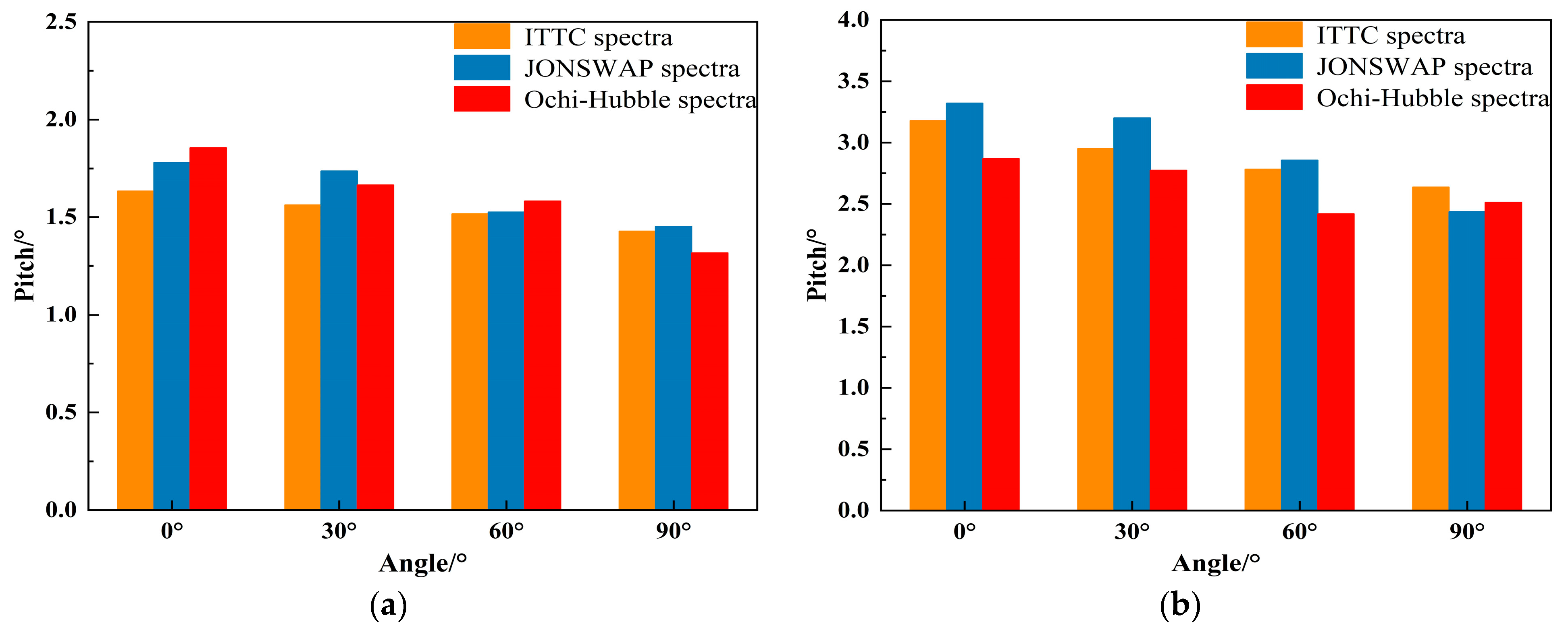
Figure 32 shows the comparison of the significant values of FPSO’s pitch motion under three different wave spectra at different incident angles. It can be seen from the figure that under the two sea conditions, the significant values of pitch motion gradually decrease for all three wave spectra as the incident angle increases from 0° to 90°. In sea state four, the significant values of pitch motion for FPSO under the three wave spectra are basically the same, with a small difference. In sea state five, the significant value of pitch motion for FPSO is the largest under the JONSWAP spectrum, and the smallest under the Ochi-Hubble wave spectrum when the incident angles are 0°, 30° and 60°. The significant value of pitch motion for FPSO is the largest under the ITTC two-parameters spectrum and the smallest under the JONSWAP spectrum when the incident angle is 90°.

4.3.4. Analysis of the Range of FPSO Motion Response

Figure 33 shows the range of FPSO’s heave motion under different wave spectra in two sea conditions. The figure indicates that the range of FPSO’s heave motion gradually increases with the incident angle from 0° to 90° for all three wave spectra. The range of FPSO’s heave motion is similar for all three wave spectra under sea condition four. The range of FPSO’s heave motion is nearly identical for all three wave spectra at the incident angles of 0° and 90° under sea condition five. The range of heave motion of FPSO under JONSWAP spectrum is the largest, and the difference in motion amplitude between the other two spectra is approximately 2 m at an incident angle of 30°. At an incident angle of 60°, the range of heave motion of FPSO is the largest under JONSWAP spectrum, and the smallest under Ochi-Hubble spectrum with a difference in motion amplitude of about 1 m.
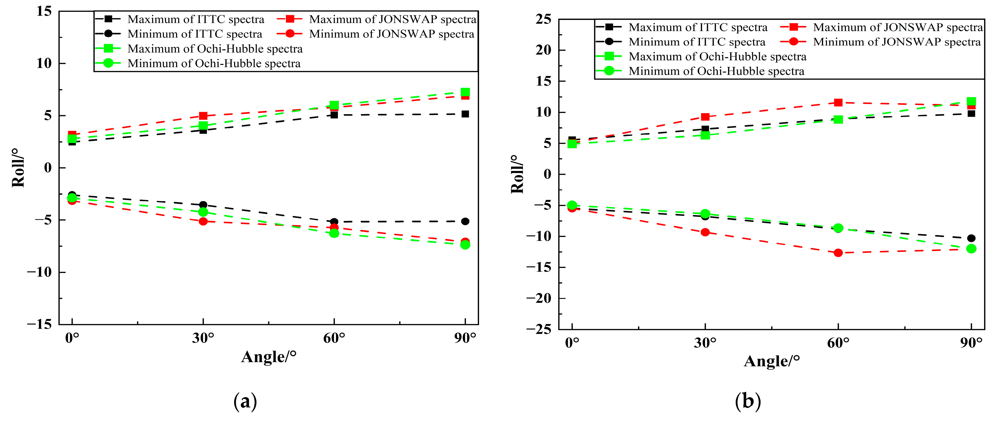
Figure 34 depicts the range of FPSO’s roll motion under different wave spectra in two sea conditions. It can be observed from the figure that the range of FPSO’s roll motion gradually increases with the increase in incident angle from 0° to 90° under all three wave spectra. Under sea condition four, the range of FPSO’s roll motion is relatively close under all three wave spectra when the incident angles are 0° and 60°. At an incident angle of 30°, the maximum range of FPSO’s roll motion occurs under the JONSWAP spectrum, while the minimum range of FPSO’s roll motion occurs under the ITTC two-parameters spectrum, with a difference of approximately 3° in roll motion. The maximum range of FPSO’s roll motion occurs under the Ochi-Hubble wave spectrum, while the minimum range of FPSO’s roll motion occurs under the ITTC two-parameters spectrum, with a difference of approximately 8° in roll motion at an incident angle of 90°. Under sea state five, the range of FPSO’s roll motion is similar under three wave spectra at the incident angle of 0°. The range of FPSO’s roll motion is the largest under JONSWAP spectrum, and similar for the other two wave spectra, with a difference of about 7° in roll motion when the incident angle is 30° and 60°. The range of FPSO’s roll motion is the largest under Ochi-Hubble spectrum and the smallest under ITTC two-parameters spectrum, with a difference of about 4° in roll motion at an incident angle of 90°.
Figure 35 displays the range of FPSO’s pitch motion under different sea wave spectra in two types of sea conditions. It can be observed from the figure that the range of FPSO’s pitch motion under three types of sea wave spectra gradually decreases with the increase in incident angle between 0° and 90°. Under sea conditions of grade four and five, the range of FPSO’s pitch motion under the three sea wave spectra are relatively close, and the range of FPSO’s pitch motion under JONSWAP spectrum is slightly larger.

5. Conclusions

Based on the theory of irregular waves, this article presents a hydrodynamic calculation program for analyzing the structural motion response under different wave spectra. Using this program, the effects of different wave spectra on the FPSO under short-crested and long-crested irregular waves are studied. Firstly, the program was used to simulate the time history wave heights of long-crested and short-crested irregular waves on a free water surface, and the time history wave heights were processed using Fourier transformation and extended maximum entropy method to obtain three generated spectra under different wave conditions. The comparison with the target spectrum showed good agreement, proving the correctness of the simulation method for irregular wave used in this article. Then, the motion response of FPSO under different sea wave spectra of long-crested and short-crested irregular waves is simulated under two sea conditions. The incident angles are 0°, 30°, 60° and 90°. The motion response spectrum, motion response amplitude and the range of motion on FPSO are analyzed. It was found that the motion amplitude of FPSOs under the three selected spectra in this paper are related to the wave type, sea conditions and incident angle. to a certain extent. The following conclusions are obtained:
1.
When the incident wave is the long-crested irregular wave, the spectral peak frequencies of the motion spectrum under three types of wave spectra is mainly near the spectral peak frequencies of the incident wave or near the natural frequencies of the vessel. Under two types of sea conditions, the heave and roll motions of FPSO under three types of wave spectra increase with the increase of the incident angle, reaching the peak value at an incident angle of 90°. The pitch motion increases first and then decreases with the increase in the incident angle, reaching the peak value at an incident angle of 30°. The significant values and ranges of heave and roll motions under JONSWAP spectrum are larger than those under the other two wave spectra. When the incident angle is 0° and 30°, the significant values and ranges of pitch motion under JONSWAP spectrum are the largest, and the range difference compared with the pitch motion under the other two wave spectra reaches about 6°. The significant values and ranges of pitch motion under the three types of wave spectra are basically the same when the incident angle is 60°.
2.
When the incident wave is the short-crested irregular wave, the spectral peak frequencies of the motion spectrum under three types of wave spectra is mainly located near the spectral peak frequencies of incident wave or near the natural frequencies of the vessel, presenting a bimodal spectrum with the main peak near the incident wave frequency and the secondary peak near the natural frequency of the vessel. Under both types of sea conditions, the heave and roll motions of FPSO under three types of wave spectra increase with the increase in incident angle and reach the peak value at an incident angle of 90°. The pitch motion decreases with the increase in incident angle, and the motion amplitude of FPSO in short-crested waves is smaller than that in long-crested waves. In the fourth-level sea state, the significant values of FPSO’s heave motion are essentially the same under three different wave spectra, and the ranges of motion are also similar. In the fifth-level sea state, when the incident angle is 60°, the significant values and ranges of FPSO’s heave motion under JONSWAP spectrum are larger than the other two wave spectra, with a difference in amplitude of 0.41 m and a difference in moving range of about 2.0 m. Under both sea states, there are significant differences in the roll motion of the FPSO under the three wave spectra at incident angles of 30°, 60° and 90°. In the fourth level sea state, the FPSO’s roll motion with the significant values and ranges occurs under the JONSWAP spectrum with an incident angle of 30°, while under the Ochi-Hubble spectrum, the FPSO’s roll motion with the significant values and ranges occurs with incident angles of 60° and 90°. In fifth level sea state, the FPSO’s roll motion with the significant values and ranges occurs under the JONSWAP spectrum with incident angles of 30° and 60°, while under the Ochi-Hubble spectrum, the FPSO’s roll motion with the significant values and ranges occurs with an incident angle of 90°. The significant values and ranges of pitch motions of the FPSO under the three wave spectra are basically similar.

Author Contributions

L.S., X.-Q.Y., S.-X.B., W.-T.Z., Y.-X.M. and Z.-L.J. contributed equally to this paper. Conceptualization Y.-X.M.; L.S. and X.-Q.Y. developed Fortran code; Z.-L.J., S.-X.B. and W.-T.Z. analyzed the data; X.-Q.Y. wrote the paper. All authors have read and agreed to the published version of the manuscript.

Funding

This research was funded by the National Natural Science Foundation of China (No. 52192692 and 52061135107), the Liao Ning Revitalization Talents Program (No:XLYC1908027), the Dalian Innovation Research Team in Key Areas (No.2020RT03), and the Fundamental Research Funds for the Central Universities (No:DUT20TD108).

Informed Consent Statement

Informed consent was obtained from all subjects involved in the study.

Conflicts of Interest

The authors declare no conflict of interest.

References

  1. Russo, S.; Contestabile, P.; Bardazzi, A.; Leone, E.; Iglesias, G.; Tomasicchio, G.R.; Vicinanza, D. Dynamic Loads and Response of a Spar Buoy Wind Turbine with Pitch-Controlled Rotating Blades: An Experimental Study. Energies 2021, 14, 3598. [Google Scholar] [CrossRef]
  2. Pierson, W.J.; Marks, W. The power spectrum analysis of ocean Wave records. Eos Trans. Am. Geophys. Union 1952, 33, 834–844. [Google Scholar] [CrossRef]
  3. Longuet-Higgins, M.S. The statistical analysis of a random, moving surface. Philos. Trans. R. Soc. Lond Ser. A Math. Phys. Sci. 1957, 249, 321–387. [Google Scholar] [CrossRef]
  4. Jiao, J.L.; Chen, C.H.; Ren, H.L. A comprehensive study on ship motion and load responses in short-crested irregular waves. Int. J. Nav. Archit. Ocean. Eng. 2019, 11, 364–379. [Google Scholar] [CrossRef]
  5. Neumann, G.M. On ocean wave spectra and a new method of forecasting wind generated sea. Tech. Memo. Beach Eros. Board 1953, 42. [Google Scholar]
  6. Pierson, W.J.; Moskowitz, L. A Proposed Spectral form for fully developed wind Seas. J. Geophys. Res. 1964, 69, 5181–5203. [Google Scholar] [CrossRef]
  7. Hasselmann, K. Measurements of wind-wave growth and swell decay during the Joint North Sea Wave Project (JONSWAP). Ergaenzungsheft Dtsch. Hydrogr. Z. Reihe A 1973, 12. [Google Scholar]
  8. Report of Seakeeping Committee. In Proceedings of the 15th International Towing Tank Conference, The Hague, The Netherlands, 3–10 September 1978.
  9. Hua, J.B. Fast simulation of nonlinear GM-variation of a ship in irregular waves. J. Ship Mech. 2000, 3, 25–34. [Google Scholar]
  10. Carrica, P.M.; Wilson, R.V.; Noack, R. A dynamic overset, single-phase Level-set approach for viscous ship flows and large amplitude motions and maneuvering. In Proceedings of the 26th Symposium on Naval Hydrodynamics, Rome, Italy, 17–22 September 2006; pp. 17–22. [Google Scholar]
  11. Carrica, P.M.; Paik, K.J.; Hosseini, H.S. URANS analysis of a broaching event in irregular quartering seas. J. Mar. Sci. Technol. 2008, 13, 395–407. [Google Scholar] [CrossRef]
  12. Renaud, M.; Rezende, F.; Waals, O.; Chen, X.B.; Dijk, R.V. Second-order wave loads on a LNG Carrier in multi-directional waves. In Proceedings of the ASME 2008 27th International Conference on Offshore Mechanics and Arctic Engineering, Estoril, Portugal, 15–20 June 2008; pp. 363–370. [Google Scholar] [CrossRef]
  13. Zheng, W.T.; Kuang, X.F.; Miao, Q.M.; Zhou, D.C. Model test study of ship motions in long-crested and short-crested irregular waves. In Proceedings of the 9th National Congress on Hydrodynamics and the 22nd National Conference on Hydrodynamics, Chengdu, China, 17–20 August 2009; pp. 359–364. (In Chinese). [Google Scholar]
  14. Chen, J.P.; Wei, J.F.; Zhu, D.X. Numerical simulations of ship motions in long-crested and short-crested irregular waves by a 3D time domain method. Chin. J. Hydrodyn. 2011, 26, 589–596. (In Chinese) [Google Scholar]
  15. Cao, H.J.; Wan, D.C. Development of multidirectional nonlinear numerical wave tank by Naoe-FOAM-SJTU solver. Int. J. Ocean Syst. Eng. 2014, 4, 49–56. [Google Scholar] [CrossRef] [Green Version]
  16. Shen, Z.R.; Ye, H.X.; Wan, D.C. URANS simulations of ship motion responses in long-crest irregular waves. J. Hydrodyn. 2014, 26, 436–446. [Google Scholar] [CrossRef]
  17. Ji, X.R.; Liu, S.X.; Harry, B.B.; Li, J.X. Multi-directional random wave interaction with an array of cylinders. Ocean Eng. 2015, 110 Pt A, 62–77. [Google Scholar] [CrossRef] [Green Version]
  18. Ducrozet, G.; Bonnefoy, F.; Touzé, D.L.; Ferrant, P. HOS-ocean: Open-source solver for nonlinear waves in open ocean based on High-Order Spectral method. Comput. Phys. Commun. 2016, 203, 245–254. [Google Scholar] [CrossRef] [Green Version]
  19. Wang, W.; Bihs, H.; Kamath, A. Multi-directional irregular wave modelling with CFD. In Proceedings of the Fourth International Conference in Ocean Engineering (ICOE2018), Chennai, India, 18–21 February 2018; Volume 22. [Google Scholar]
  20. Jiao, J.L.; Yu, H.C.; Chen, C.H.; Ren, H.L. Time-domain numerical and segmented model experimental study on ship hydroelastic responses and whipping loads in harsh irregular seaways. Ocean Eng. 2019, 185, 59–81. [Google Scholar] [CrossRef]
  21. Zhang, L.; Zhang, J.N.; Shang, Y.C. A practical direct URANS CFD approach for the speed loss and propulsion performance evaluation in short-crested irregular head waves. Ocean Eng. 2021, 219, 108287. [Google Scholar] [CrossRef]
  22. Zhang, H.C.; Liu, S.X.; Li, J.X. Multi-directional irregular wave forces acting on a tandem pile group. Appl. Ocean Res. 2023, 135, 103542. [Google Scholar] [CrossRef]
  23. Goda, Y. A comparative review on the functional forms of directional wave spectrum. Coast. Eng. J. 1999, 41, 1–20. [Google Scholar] [CrossRef]
  24. Ochi, M.K.; Hubble, E.N. Six-parameter wave spectra. In Proceedings of the 15th International Conference on Coastal Engineering, Honolulu, HI, USA, 11–17 July 1976; pp. 301–328. [Google Scholar] [CrossRef]
  25. Zhang, X.; Wu, L.; Zhang, L.; Long, L. Ocean wave simulation based on JONSWAP spectrum. Infrared Laser Eng. 2018, 47, 162–167. [Google Scholar]
  26. Goda, Y. Numerical experiments on wave statistics with spectral simulation. Rep. Port Harb. Res. Inst. 1970, 9, 3–57. [Google Scholar]
  27. Tessendorf, J. Simulating ocean water. In Proceedings of the ACM SIGRAPH, New York, NY, USA, 8–13 August 1999; pp. 348–367. [Google Scholar]
  28. Wang, H.T. Temporal and spatial simulation of random ocean wave. In Proceedings of the Fourth International Offshore Mechanics and Arctic Engineering Symposium, Dallas, TX, USA, 17–21 February 1985; pp. 72–80. [Google Scholar]
Figure 1. Sketch of the model.
Jmse 11 01467 g001
Figure 2. Comparisons of displacement of sink and pitch at different number of grids.
Jmse 11 01467 g002
Figure 3. Meshing diagram of the FPSO: (a) Object surface mesh; (b) Free water surface mesh.
Jmse 11 01467 g003
Figure 4. Comparisons of displacement of sink and pitch at different time steps.
Jmse 11 01467 g004
Figure 5. The RAO of FPSO with 0°incident wave: (a) Heave; (b) Pitch.
Jmse 11 01467 g005
Figure 6. The RAO of FPSO with 90°incident wave: (a) Heave; (b) Roll.
Jmse 11 01467 g006
Figure 7. Comparison of target spectra and generate spectra under long-crested wave.
Jmse 11 01467 g007
Figure 8. Comparison of ITTC spectra under short-crested wave: (a) Target spectra; (b) Generation spectra.
Jmse 11 01467 g008
Figure 9. Comparison of JONSWAP spectra under short-crested wave: (a) Target spectra; (b) Generation spectra.
Jmse 11 01467 g009
Figure 10. Comparison of Ochi-Hubble spectra under short-crested wave: (a) Target spectra; (b) Generation spectra.
Jmse 11 01467 g010
Figure 11. Free surface field of FPSO under different incident wave: (a) Irregular long-crested waves; (b) Irregular short -crested waves.
Jmse 11 01467 g011
Figure 12. The motion response of FPSO under different wave spectra at long-crested wave incidence: (a) Heave; (b) Roll; (c) Pitch.
Jmse 11 01467 g012aJmse 11 01467 g012b
Figure 13. Frequency analysis of heave at 0° incidence: (a) Class IV sea state; (b) Class V sea state.
Jmse 11 01467 g013
Figure 14. Frequency analysis of pitch at 0° incidence: (a) Class IV sea state; (b) Class V sea state.
Jmse 11 01467 g014
Figure 15. Frequency analysis of heave at 90° incidence: (a) Class IV sea state; (b) Class V sea state.
Jmse 11 01467 g015
Figure 16. Frequency analysis of roll at 90° incidence: (a) Class IV sea state; (b) Class V sea state.
Jmse 11 01467 g016
Figure 17. The heave motion significant value of FPSO under different wave spectra: (a) Class IV sea state; (b) Class V sea state.
Jmse 11 01467 g017
Figure 18. The roll motion significant value of FPSO under different wave spectra: (a) Class IV sea state; (b) Class V sea state.
Jmse 11 01467 g018
Figure 19. The pitch motion significant value of FPSO under different wave spectra: (a) Class IV sea state; (b) Class V sea state.
Jmse 11 01467 g019
Figure 20. The heave motion maximum and minimum of FPSO under different wave spectra: (a) Class IV sea state; (b) Class V sea state.
Jmse 11 01467 g020
Figure 21. The roll motion maximum and minimum of FPSO under different wave spectra: (a) Class IV sea state; (b) Class V sea state.
Jmse 11 01467 g021
Figure 22. The pitch motion maximum and minimum of FPSO under different wave spectra: (a) Class IV sea state; (b) Class V sea state.
Jmse 11 01467 g022
Figure 23. The motion response of FPSO under different wave spectra at short-crested irregular wave: (a) Heave; (b) Roll; (c) Pitch.
Jmse 11 01467 g023
Figure 24. Frequency analysis of heave at 0° incidence: (a) Class IV sea state; (b) Class V sea state.
Jmse 11 01467 g024
Figure 25. Frequency analysis of roll at 0° incidence: (a) Class IV sea state; (b) Class V sea state.
Jmse 11 01467 g025
Figure 26. Frequency analysis of pitch at 0° incidence: (a) Class IV sea state; (b) Class V sea state.
Jmse 11 01467 g026
Figure 27. Frequency analysis of heave at 90° incidence: (a) Class IV sea state; (b) Class V sea state.
Jmse 11 01467 g027
Figure 28. Frequency analysis of roll at 90° incidence: (a) Class IV sea state; (b) Class V sea state.
Jmse 11 01467 g028
Figure 29. Frequency analysis of pitch at 90° incidence: (a) Class IV sea state; (b) Class V sea state.
Jmse 11 01467 g029
Figure 30. The heave motion significant value of FPSO under different wave spectra: (a) Class IV sea state; (b) Class V sea state.
Jmse 11 01467 g030
Figure 31. The roll motion significant value of FPSO under different wave spectra: (a) Class IV sea state; (b) Class V sea state.
Jmse 11 01467 g031
Figure 32. The pitch motion significant value of FPSO under different wave spectra: (a) Class IV sea state; (b) Class V sea state.
Jmse 11 01467 g032
Figure 33. The heave motion maximum and minimum of FPSO under different wave spectra: (a) Class IV sea state; (b) Class V sea state.
Jmse 11 01467 g033
Figure 34. The roll motion maximum and minimum of FPSO under different wave spectra: (a) Class IV sea state; (b) Class V sea state.
Jmse 11 01467 g034
Figure 35. The pitch motion maximum and minimum of FPSO under different wave spectra: (a) Class IV sea state; (b) Class V sea state.
Jmse 11 01467 g035
Table 1. Main parameters of the FPSO.
UnitsValue
Length overallm112
Length between perpendicularsm109
Breathm28
Draftm9
Displacementt24,610
Longitudinal center of gravity
(to the stern of the ship)
m51
Vertical center of gravity
(to the hull baseline)
m7.2
Roll radius of inertiam8.037
Pitch radius of inertiam28.149
Yaw radius of inertiam29.027
Table 2. Sea wave conditions under different spectral shapes.
Ocean Wave SpectraThe Significant Wave HeightThe Spectral Peak
Period
The Peak Elevation
Parameter
ITTC two-parameters spectra3.6 m/2.0 m10.59 s/9.84 s/
JONSWAP spectra3.3
Ochi-Hubble spectra/
Disclaimer/Publisher’s Note: The statements, opinions and data contained in all publications are solely those of the individual author(s) and contributor(s) and not of MDPI and/or the editor(s). MDPI and/or the editor(s) disclaim responsibility for any injury to people or property resulting from any ideas, methods, instructions or products referred to in the content.