1. Introduction
As the multi-agent theory has become a research hotspot in the field of robots and UAVs (unmanned aerial vehicles) [
1,
2,
3], the multi-AUV (multiple autonomous underwater vehicle) system has also become one of the hot directions of many research institutions due to its better data redundancy and system robustness compared with the single AUV system, and it has been widely used in marine development, oceanographic survey, submarine rescue, underwater target tracking, and so on [
4,
5,
6,
7,
8].
Guidance, navigation and control (GNC) is an important part of the control system, which is core to supporting the normal operation of each system and achieving goals, and is the key to the success of the mission. The experimental results of guidance, navigation and control (GNC) of a new superdriven unmanned surface vessel (USV) obtained during sea trials under real environmental conditions are presented in [
9]. The USV has a wide range of applications in diver tracking, long-term marine environment monitoring, mine countermeasures and so on. In order to enable UAVs to perform observation tasks autonomously, an airborne architecture has been proposed [
10]. At the heart of the architecture is the execution controller used in the application, combined with a Petri net, to specify the behavior of the vehicle in normal and degraded situations, and to manage the process of the task. Ref. [
11] extended the typical GNC software architecture to enable autonomous surface vehicles (ASVs) to coordinate tasks autonomously (M-GNC architecture). Ref. [
12] introduced a software architecture for autonomous UAV mission management and control that can generate a flight plan, execute that plan, and update it as it seeks to respond to changes in the perceived environment. In order to equip low-cost autonomous vehicles, a multi-agent NGC system was designed in [
13], which also improved the reliability of local faults.
For a multi-AUV system, a well-designed architecture can not only maximize the function of the system, but also reduce the development cycle and difficulty of the system. From the perspective of control, the architecture of a multi-AUV system can be divided into two categories: centralized and distributed [
14,
15]. The centralized structure is a master–slave structure. The system control center is responsible for collecting information and sending it to each vehicle. Therefore, there is strong dependence on the control center, and the failure of the control center or communication system will lead to the collapse of the whole system [
16]. Compared with the centralized system, each member in the distributed system structure has the same status and has the ability to make independent decisions. The distributed system structure can coordinate the completion of system tasks through information sharing among members, so it avoids dependence on the control center, and greatly improves the robustness of the system [
17,
18]. Therefore, the multi-AUV system studied in this paper adopts a distributed architecture.
For multi-AUVs, stable formation can enhance the security, coordination, and consistency of task execution of multi-AUVs when performing trajectory tracking tasks [
19,
20]. From the perspective of multi-agent coordination control, formation control is the core of this task. Corresponding to the formation control methods of multi-agents, the formation control methods of multi-AUVs include the leader–followers method, the virtual structure method, the sliding mode control method and consistency theory, and so on [
21,
22,
23]. However, the main control methods used in this paper include the virtual structure method and the leader–followers method, which transform the formation tracking task of multi-AUVs into the formation coordinated control problem of leader–followers formation.
The multi-AUV formation mainly communicates underwater through underwater acoustic communication when it performs a trajectory tracking task [
24]. However, due to interference from the marine environment, such as ocean noise, ocean currents and unknown obstacles, as well as the limitations of the vehicle itself, the status information of the multi-AUV formation may be distorted such that the formation cannot form a stable formation during the trajectory tracking task [
25,
26,
27,
28]. Therefore, the weak communication conditions, which are dominated by delay, data loss and ocean noise, represent some of the difficult problems encountered in the coordinated control of multi-AUV formation. In this paper, the influence of a weak communication environment on the coordination control of multi-AUV formation is also considered when the trajectory tracking task of multi-AUV formation is discussed.
Due to environmental interference, task requirements, and the constraints of the agent’s own conditions, the multi-agent control input may need to meet the requirements of nonconvex constraints [
29]. In practice, nonconvex control constraints have a wide range of applications, such as UAV escort formation, multi-robot cooperative obstacle avoidance, etc. [
30,
31,
32,
33]. However, their application in multi-AUV systems is rarely studied. In our previous work, the problem of nonconvex constraints was not discussed [
34,
35]. Starting from [
34], the consistency problem of multi-AUV systems with velocity state constraints in nonconvex sets was considered. Then, [
35] studied the formation consistency problem of leaderless multi-AUVs with nonconvex control constraints. However, practical problems were not considered by these authors. Therefore, the formation trajectory tracking of multi-AUVs with control input constraints in nonconvex sets is discussed in this paper.
By reason of the foregoing, this paper mainly discusses the formation trajectory tracking problem of discrete-time distributed multi-AUVs with control input in a nonconvex set under weak communication conditions. The main contributions are summarized as follows:
The formation trajectory tracking problem of multi-AUVs is transformed into the coordination control problem of leader–followers formation. Aiming at the weak communication environment and nonconvex control constraints, a discrete-time distributed constraint controller with bounded communication delay is proposed;
Through coordinate transformation, the formation trajectory tracking problem is finally transformed into the error stability problem of leader and followers in relative positions. A definition of the trajectory tracking stability of multi-AUV formation is also given;
On the basis of graph theory, an appropriate Lyapunov–Krasovskii function is constructed. By solving the linear matrix inequalities, the conditions for multi-AUVs to form a stable formation and realize trajectory tracking are obtained.
The rest of the article is organized as follows: The related concepts of graph theory, linear models of AUVs, the formation coordination control system of multi-AUVs, and related lemmas are mainly introduced in
Section 2. The formation trajectory tracking problem of multi-AUVs is analyzed, the coordination controller is designed, and the definition of consistency and stability is given in
Section 3. The stability conditions of multi-AUVs with nonconvex control input constraints and weak communication conditions for formation trajectory tracking are discussed in
Section 4. A simulation experiment is described in
Section 5. The work of the paper is summarized and prospective future work is discussed in
Section 6.
2. Preliminaries
2.1. Graph Theory
The communication topology represents the nature of the information interaction between AUVs in the multi-AUV system, and is usually represented by a digraph. Assuming that the multi-AUV system discussed in this paper contains n AUVs, is the digraph related to the multi-AUV system. represents the set of nodes, represents the set of edges, and the adjacency matrix associated with the digraph is represented as , . If , which means that the node j can receive the information of the node i, , otherwise . The nodes i and j are called a parent node and a child node in , respectively. But the root node has no parent node. stands for the set of neighbors of node i. The combination of edges is defined as a directed path. In a digraph, if all the nodes except one root node have parent nodes, and there is a directed path connecting all other nodes on the root node, the digraph is said to have a directed spanning tree. The matrix is the Laplace matrix, which satisfies . The matrix represents an in-degree matrix, where .
In order to reduce the influence of weak communication conditions on the formation trajectory tracking of multi-AUVs, a double independent position-velocity communication topology is selected in this paper. represents the position communication topology, represents the velocity communication topology, and , , , , , , respectively, represent the adjacency matrix, Laplacian matrix and in-degree matrix related to and .
2.2. The Model of AUV
When considering the formation trajectory tracking problem of multi-AUVs, the nonlinear and strong coupling of the dynamic model of the AUV will increase the coordination controller design of the multi-AUV formation. Therefore, the feedback linearization method is adopted in this part, and the coordinate transformation and Lie derivative theory are used to transform the AUV model into a second-order linear model. On this basis, the structure of a multi-AUV coordination control system is designed.
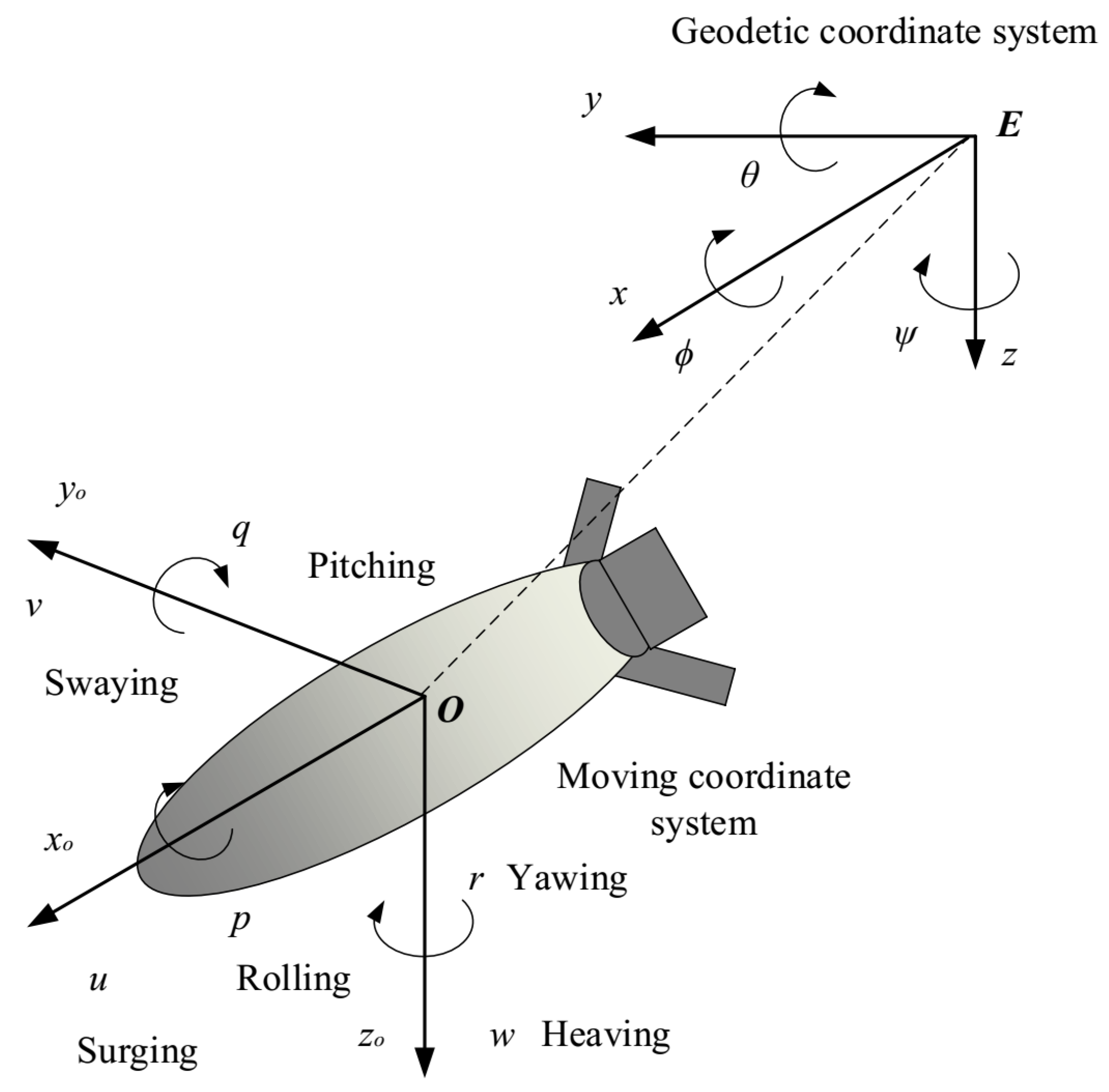
First, model the AUV as shown in
Figure 1.
In
Figure 1,
and
represent a geodetic coordinate system and moving coordinate system, respectively;
x(
),
y(
) and
z(
) represent the north position, the east position and the depth;
,
and
represent the roll angle, pitch angle and heading angle. In addition, the meaning of
u,
v,
w,
p,
q, and
r has been written out in the figure, and will not be repeated here. However, it is worth noting that the AUV studied in this paper is up-down symmetric and left-right symmetric. As a result, large roll damping will be generated during the AUV motion. Therefore, the roll angle and roll angular velocity of the AUV are ignored in this paper when designing the control system, namely,
and
[
36]. In our previous article [
17], the conditions for feedback linearization of the system were given, so it will not be repeated in this article. The feedback linearization process is presented below.
Secondly, according to the modeling in
Figure 1, the kinematic equation and dynamic equation of the AUV are given, as shown below.
where
,
,
and
.
,
,
and
represent the inertia mass matrix, the matrix of Coriolis forces and centripetal forces, the hydrodynamic damping coefficient matrix and the buoyancy and gravity vector, respectively.
represents the control input force and torque. In addition, the matrix
is represented as follows:
In order to feedback linearize the AUV model (
1) and (2), the mathematical model of the AUV is expressed as the following general nonlinear model:
where
stands for the system state vector,
stands for the system output vector,
stands for the control input vector, and
,
,
stand for the corresponding system functions.
Let
,
,
. Then, according to the Lie derivative theory, the feedback linearization model of the AUV can be expressed as
where
,
,
. Details can be found in reference [
17].
Assuming that each AUV in the multi-AUV formation studied in this paper has the same model, then the formation coordination control system of for multi-AUVs is designed as shown in
Figure 2.
Where , , , , stand for the position state, the velocity state and the control input of the ith AUV(AUV) in the multi-AUV formation, respectively. It can be seen from picture 2 that, for the formation trajectory tracking problem of multi-AUVs mentioned in this paper, the main problem to be faced is how to design an appropriate coordination controller and find appropriate controller parameters so that the multi-AUV system can form and maintain a stable formation when executing trajectory tracking tasks.
2.3. Relevant Lemmas
The main lemmas involved in this paper are given below.
Lemma 1 ([
37])
. For any and any positive-definite matrix , we have the following inequality Lemma 2 ([
38])
. For a given matrix with , , then , if, and only if, , , or equivalently , . 3. Problem Formulation
In this part, by analyzing the trajectory tracking problem of multi-AUV formation, an appropriate coordination controller is designed, and the definition of formation stability is given.
When the multi-AUV formation executes a trajectory tracking task, the trajectory of the formation should be consistent with the trajectory of the AUV
. In addition, in order to ensure that the relative position relationship between individuals in the multi-AuV formation does not change, the fixed multi-AUV formation should be maintained. According to the above characteristics, the formation trajectory tracking problem of multi-AUVs can be regarded as a typical formation coordinated control problem of multi-AUVs. In order to realize the trajectory tracking of formation, the trajectory of AUV
is not affected by other individuals in the multi-AUV formation and does not need to receive information from other vehicles during task execution. Therefore, in the communication structure diagram, AUV
is usually represented as a node with 0 in degree; that is, AUV
is regarded as the leader of the multi-AUV formation, as shown in
Figure 3a.
The formation trajectory tracking of discrete-time multi-AUVs is discussed in this paper. So, assuming that
T is the control period of the discrete system,
is the discrete-time index,
is the position state of AUV
at time
,
time
, and
is the expected position deviation of AUV
and AUV
,
, as shown in
Figure 3b. Then, the expected position state and expected velocity state of AUV
at time
when executing the trajectory tracking task type can be expressed as
Therefore, when the trajectory tracking task is executed, the formation coordinated control target of multi-AUV can be written as
Define
Then, the formation coordinated control target (
10) and (11) of multi-AUVs can be equivalently expressed as
By Taylor expansion of (
6), the discrete-time model of AUV
in multi-AUV formation can be written as follows:
where
,
,
,
,
is a non-empty nonconvex set. And the following assumption is made about
.
Assumption 1 ([
39])
. For , are non-empty bounded closed sets, and , there are positive constants and , such that and . Then, the constraint operator is defined as In Assumption 1,
represents the upper bound of the distance from any point in the
to the origin
. Therefore, it can be seen that the control input of all AUVs in the formation cannot be arbitrarily large.
is a positive constant associated with the
that represents the lower bound on the distance to the origin from any point outside the
. Thus, each AUV can move in any direction. And it also can be seen from Assumption 1 that any vector,
,
, can be made to lie in the nonconvex set
by the operator
. And
is the largest vector in the set
that has the same direction as the vector
, as shown in
Figure 4.
The influence of a weak communication environment on formation trajectory tracking is also considered in this paper, so the formation may have a communication delay during the course of the trajectory tracking task. Let , be the position communication delay and speed communication delay of at , respectively. Then, the following definitions are given for , and multi-AUV formation:
Definition 1. In a multi-AUV formation, and represent the position communication delay and the velocity communication delay at time .
- 1.
For all k, if there exists a positive integer , and constant , such that , ; then, the multi-AUV formation is said to have a bounded communication delay, and are called bounded communication delays.
- 2.
For any positive integer N, if there exists such that or , then, the multi-AUV formation is said to have an unbounded communication delay; or are called unbounded communication delays.
Remark 1. If, for all k, , , it means that the system has no communication delay; if there is or , it means that the system has a communication delay under weak communication conditions. According to Definition 1, when and are bounded communication delays, and can be denoted as , . Thus, it can be seen that, when (or ), (or ); that is, there is no communication delay in the position (velocity) topology of AUV and AUV. Furthermore, if, for all , , , then, the multi-AUV formation has no communication delay; that is, no communication delay can be regarded as a special case of bounded communication time delay. Therefore, the case of no communication delay is not listed separately in Definition 1.
Based on the above analysis, the coordination controller for formation trajectory tracking of multi-AUV is given as follows:
where
,
,
are the feedback gain matrix at time
, and
,
,
,
,
,
are bounded; that is, there are positive integers
,
, such that
,
,
,
,
,
.
For all
, define
where
In particular, when
,
. So
. Then, controller
can be represented linearly as
Let
Then, the error dynamics of multi-AUV formation with constraint controller (
18) can be written as
where
,
,
,
,
,
,
,
,
,
,
,
.
Assumption 2. Assume that the position topology and velocity topology discussed in this paper are fixed, and both contain a spanning tree, with the leader as the root node of the spanning tree.
Then, the definition of formation stability is given below.
Definition 2 ([
40])
. The multi-AUV formation (16) is said to reach exponential consensus under the constraint controller (18) if the error dynamics of the multi-AUV formation (24) are exponentially stable with a convergence rate , i.e., there exist scalars , , such that where . 4. Results
In this section, the stability conditions for multi-AUVs to realize formation trajectory tracking targets and the selection of relevant parameters in the constraint controller under a stable state are presented.
Theorem 1. Assuming that Assumptions 1 and 2 holds, for a given scalar , the formation trajectory tracking problem of multi-AUVs (16) with a constrained coordination controller (18) can be solved if there exists a matrix , , , , , , and matrixes such that the following LMI holds:where Proof of Theorem 1. Define
then, the Lyapunov–Krasovskii function is constructed as follows.
where
,
,
and
are specifically represented as
,
,
,
,
,
are the positive-definite matrices that need to be solved. And by matrix operation, the following error equations can be obtained.
where
; then, according to Lemma 1, we have
and
Through calculation, the following inequality is obtained.
Obviously,
, if the LMI in Theorem 1 holds, then, according to Lemma 2, it can be obtained that
; that is,
. So, for all
k, we have
.
Furthermore, the positive scalars
,
are defined as
By combining Equations (
29) and (
30), the following inequality can be easily obtained.
Finally, by solving the above inequality (
31), the desired inequality can be obtained below.
where
; then, according to stability Definition 2, the multi-AUV (
16) can realize stable formation trajectory tracking. So, Theorem 1 is proved. □
It can be seen from Theorem 1 that, when the multi-AUV formation reaches a given stable state, the state errors of the follower and the leader are bounded and monotonically decreasing with time. Therefore, according to Theorem 1, the following corollary is given.
Corollary 1. If the multi-AUV formation (16) can reach the stable state in Theorem 1 when executing the trajectory tracking task, then, for all the , Proof of Corollary 1. According to Assumption 1 and the Euclidean norm algorithm, the following two inequalities can be obtained:
where
is the
jth component of vector
,
.
Then, combined with the definition of
, (
33) can be easily obtained. Therefore, Corollary 1 is proved. □
A sufficient condition for multi-AUVs to realize formation trajectory tracking is given in Theorem 1. In the following, on the basis of Theorem 1, the selection of a correlation coefficient when the multi-AUV formation is maintained stable is discussed.
Theorem 2. Assuming that Assumption 1 and 2 holds, for a given scalar , if there exists a matrix , and matrix such that the following LMI holds,whereμ is a positive number. Then, the formation trajectory tracking problem of multi-AUV (16) with a constrained coordination controller (18) can be solved, and , . Proof of Theorem 2. Define
where
,
and
are positive-definite matrices. Then, according to Lemma 2 and Theorem 1, the LMI can be obtained as follows [
41]:
Since the solution process of the inverse matrix of the partitioned matrixes
,
and
is too complicated, the partitioned matrixes
,
and
are sorted out below [
42].
Similarly,
Furthermore, let
,
,
,
,
,
. Pre- and post-multiplying LMI (
35) by the partitioned matrix
,
, then, the following equation can be obtained.
Therefore, when LMI (
34) holds, the multi-AUV system can realize formation trajectory tracking and maintain the formation stability, then,
,
. Theorem 2 is proved. □
For Theorem 2, as long as
,
, and
are selected so that the diagonal elements of
,
,
,
and
are less than zero, and the absolute value phase of the diagonal elements is large enough, and the absolute value of the non-zero elements of
is small enough, then, LIMI (
34) can be easily obtained [
43]. However, it is worth noting that the positive-definite matrix
is a diagonal matrix by default in this paper. And the diagonal elements are the same. Therefore, in the proof of Theorem 2, pre- and post-multiplying LMI (
35) by the matrix
, it is actually pre- and post-multiplying LMI (
35) by matrixes
and
, and, after the operation, the communication topology form of multi-AUV will not be changed.
The design of the above controller
is based on the case of bounded communication delay, but the weak communication environment may also lead to the existence of unbounded communication delay, so that the AUV cannot receive the transmitted information. In the case of unbounded communication delay, the values of
and
are set as follows:
where
is an appropriate positive integer, which is usually selected according to the actual situation. In this case, the trajectory tracking problem of multi-AUV formation with unbounded communication delay is transformed into the trajectory tracking problem of multi-AUV formation with bounded communication delay. Therefore, relevant conclusions in this paper are also applicable to the case of unbounded communication delay. At the same time, this method can also be used when the communication delay is bounded but the communication delay is too large.
Remark 2. In this paper, the formation trajectory tracking problem of multi-AUVs is transformed into the error stability problem of leader–followers formation. By constructing the corresponding Lyapunov–Krasovskii function, the stability condition of the formation is obtained; that is, the condition that the multi-AUV formation in Theorems 1 and 2 can realize stable trajectory tracking. This method is also adopted for the leader–followers formation coordination control problems discussed in [42,43]. However, compared with [42,43], the formation trajectory tracking problem of multi-AUVs discussed in this paper adopts the double independent position-velocity communication topology, which means that the velocity communication delay and position communication delay of the multi-AUV formation may be different, which can reduce the influence of a communication delay on the convergence speed of formation to a certain extent. Moreover, the constraint coordination controller designed in this paper can also solve the nonconvex control input constraint problem of multi-AUV formation, which is not considered in [42,43]. 5. Simulation
In this part, the conclusions of this paper are verified by simulation experiments. It is assumed that the multi-AUV formation consists of one leader and five followers. The double independent position-velocity communication topology is shown in
Figure 5, where AUV
is the leader of the formation, and AUV
,
are the followings of the formation.
Because the same time-varying delay can be regarded as a special case of different time-varying delays, different time-varying time delays are adopted in the simulation of this paper. Then, the different time-varying delay is selected as
In this case,
, so it can be obtained that
,
. According to
Figure 5, the Laplacian matrixes
,
,
and
corresponding to the communication topology
and
are represented as
According to the definition of the constraint controller (
18),
is chosen as
, in which case,
is satisfied. In the multi-AUV formation, the initial position of each follower in three-dimensional space is arbitrarily distributed as
,
,
, and other states are selected as
,
,
,
. The initial position of the leader in the formation is
,
,
, and other states are selected as
,
,
,
. The relative expected positions of the followers and the leader are
,
,
,
,
, respectively. Suppose that the path of trajectory tracking is a spiral curve in space. The specific form is shown below.
According to the conditions of nonconvex control input constraints, the nonconvex control set is selected as
Then,
.
Based on the above assumptions, the control period
T is selected as
, the discrete-time index
k is
, the convergence rate
is
, the control gain matrices of the multi-AUV formation coordination controllers are
and
, respectively. Then, according to Theorems 1 and 2, it can be obtained that
. Finally, combined with the above data and the feedback linearization structure in
Figure 2, the simulation program is designed. The simulation experiment results are shown in
Figure 6,
Figure 7,
Figure 8,
Figure 9 and
Figure 10.
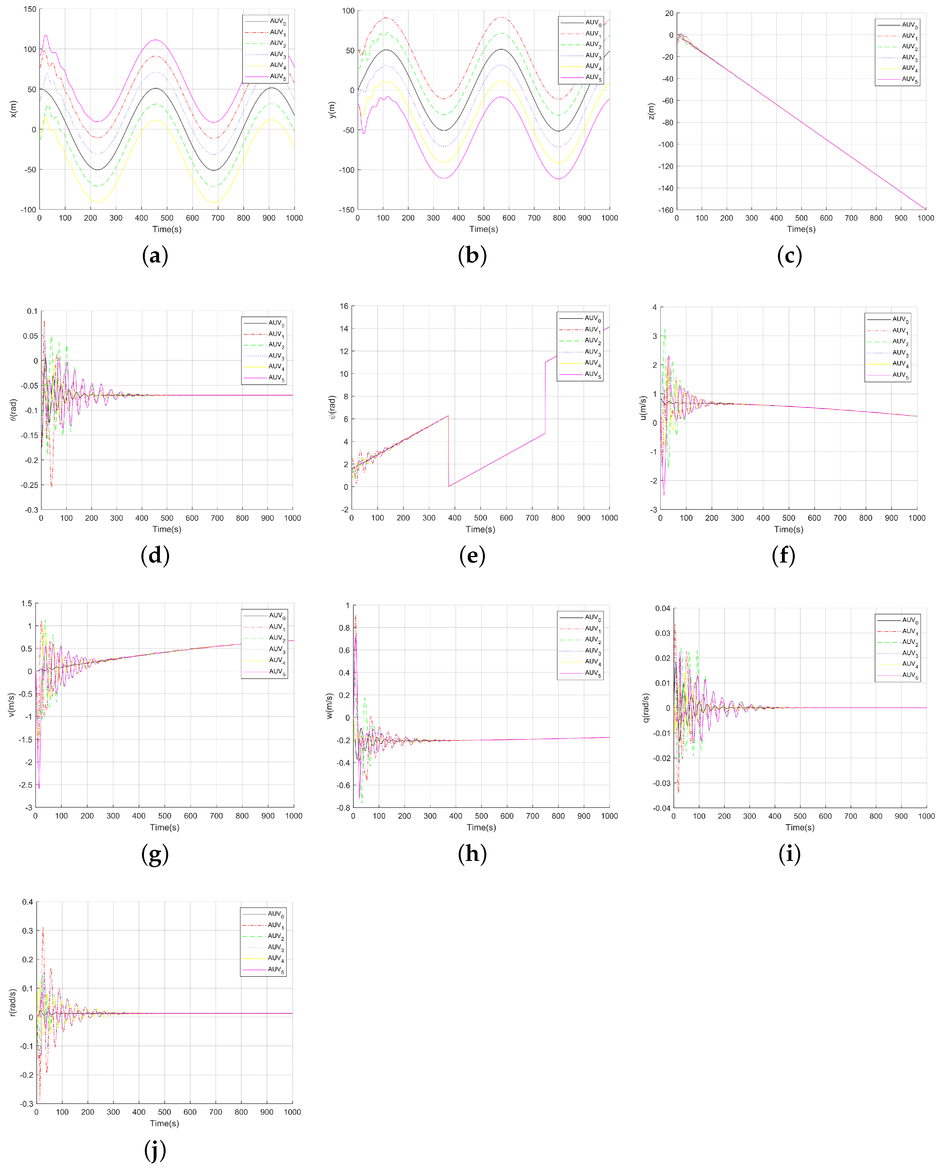
It can be seen from picture
Figure 6 that all states of the followers in the multi-AUV formation are consistent with each state of the leader in the desired position at
t = 500 after a period of adjustment. Moreover, the leader–followers formation of multi-AUVs can maintain the consistency in the process of subsequent movement.
On the basis of
Figure 6, the relative errors of the leader and the follower in the multi-AUV formation without considering the relative positions are shown in
Figure 7. It can be seen from
Figure 7 that all state errors approach zero after 500 s of change and can remain stable at zero after 500 s. Moreover, according to
Figure 7,
in Corollary 1 can be obtained as
; then, a non-zero bound of
can be obtained by combining the above values of
,
,
and
; that is, for all
,
satisfies
.
Figure 8 is the state change diagram of the constrained coordination controller
. Compared with the state
Figure 9 of
without the action of the nonconvex operator
in Assumption 1, it can be easily seen that, for all
, the controller
lie in the specified nonconvex set
. Among them, the comparison between
Figure 8a and
Figure 9a is more obvious. Where
and
represent the
ith component of
and
, respectively.
In
Figure 10, the three-dimensional trajectory diagram of multi-AUV formation is given.
Figure 10a shows the trajectory to be tracked and the trajectory of the followers, and
Figure 10b shows the formation of the formation at
,
,
,
and
during the trajectory tracking process, respectively. From
Figure 10, it can be seen that, after a period of adjustment, the movement trajectory of the follower AUV
, AUV
, AUV
, AUV
and AUV
in the multi-AUV formation can be consistent with the trajectory of the tracked person (leader AUV
) at their opposite position, and the formation can maintain a stable formation when it reaches a consistent state.
From the above simulation results, it can be seen that, under the condition of weak communication, the multi-AUV formation (
16) with a constrained coordination controller (
18) confined to a nonconvex set can achieve stable trajectory tracking under the conditions of Theorems 1 and 2.
6. Conclusions
In this paper, the formation trajectory tracking problem of discrete-time distributed multi-AUVs with control input constraints in a nonconvex set is studied. Firstly, the monomer AUV is modeled, and the linear model of the monomer AUV is obtained to solve the complicated problem of nonlinear model calculation. Secondly, the tracked trajectory is regarded as the trajectory of the leader, and the tracker is regarded as the follower; then, the formation trajectory tracking problem of the multi-AUV is transformed into the coordinated control problem of leader–followers. and the linear model of the multi-AUV formation in discrete time, the feedback linearized structure of multi-AUV formation and the stability definition of the formation trajectory tracking problem of multi-AUVs. Next, based on the linear model of discrete time multi-AUV formation, the feedback linearization structure of multi-AUV formation, and the stability definition of the formation trajectory tracking problem of multi-AUVs, a constrained coordination controller with bounded communication delay is presented for the formation trajectory tracking problem of multi-AUVs. The formation trajectory tracking problem of multi-AUVs is transformed into the error stability problem of the leader and the follower by coordinate transformation. On the basis of graph theory, by constructing an appropriate Lyapunov–Krasovskii function and solving linear matrix inequalities, the conditions of multi-AUVs to realize stable formation trajectory tracking are obtained. Moreover, these conclusions are also applicable to the case of unbounded communication. That is, the trajectory tracking problem of multi-AUV formation in this paper can be solved. Finally, the conclusion of this paper is verified by simulation experiments. Although the case of communication delay in a weak communication environment is discussed in this paper, the case of packet loss and the case of marine environment interference, such as by obstacles, are not considered. Therefore, this is the main content to be studied in the future.


