Project Report

Implementation of International Regulations for Preventing Collisions at Sea Using Coloured Petri Nets

1
SEAL AG, 5430 Wettingen, Switzerland
2
Faculty of Maritime Studies, University of Split, 21000 Split, Croatia
3
Electrical Engineering and Computing Department, University of Dubrovnik, 20000 Dubrovnik, Croatia
*
Author to whom correspondence should be addressed.
These authors contributed equally to this work.
J. Mar. Sci. Eng. 2023, 11(7), 1322; https://doi.org/10.3390/jmse11071322
Submission received: 15 April 2023 / Revised: 27 May 2023 / Accepted: 26 June 2023 / Published: 29 June 2023
(This article belongs to the Section Ocean Engineering)

Abstract

:
The purpose of this study is to show how coloured Petri nets can be used to select the crossing rules guaranteeing that two ships avoid collisions at sea in accordance with the international regulations on this matter. This paper is exclusively focused on the solution to this small sub-problem within the overall “Collision Avoidance System” that the authors of the present study are currently developing. For easier understanding, the overall system is also briefly presented. How the Petri net in the CPN Tools software is fed with “Real Time Real World” data is presented. These data are generated outside the Petri net from the function block to predict a possible collision and from the current meteorological data. We also demonstrate how the rule selections made by the Petri net are transferred from the CPN Tools software into the “Real Time Real World”. This transferred information is used outside the Petri net in the function block to calculate avoidance routes. The definition of the colour sets that are used and the individual operations applied to these colour sets in the coloured Petri net are presented.

1. Introduction

In a collision-avoidance system, different methods can be used to detect the danger of a potential collision. One of these methods is presented in [1]. The method described in the referenced article considers several ships at the same time and the system searches for evasive routes according to international rules (also known as COLREG [2]). Unfortunately, this implementation only considers some main COLREG rules and not the different propulsion types (power-driven, sailing), propulsion status (e.g., normal, limited maneuverability), function (e.g., fishing, laying), priority (e.g., passenger ship, military ship), etc. Another method of route determination according to COLREG, shown in [3], is based on neural networks, assumes a general ship model, and unfortunately also does not consider the parameters listed above. A method based on discrete events is described in [4]. This method considers events such as ship from right and head-on and reacts according to COLREG guidelines. Such a method could be realized with classical Petri nets. However, this method, like the two previously mentioned methods, does not consider different ship types and priorities. It is assumed that it is possible, with the help of digital signal processing methods, to quite accurately calculate future ship positions (coordinates at certain time points) based on the huge amount of data generated from various sources. This would allow for the accurate and reliable detection of a collision hazard.
When calculating an alternate route for real system deployment at present, different types of knowledge should be combined, such as the maneuvering capabilities of ships at their current draft, evident from the AIS data, in current weather conditions received as an S-413 data set, in an aquatorium described with a chart set in S-101 format, with additional navigational warnings in S-124 format, etc. The meaning of individual numbers in the S-100 standard can be read in [5]. A fairly accurate calculation of a new route, specifiying ship position, course, velocity and rate of turn as a function of time, is based, among other things, on the use of modern database techniques [6]. It requires much more computing power than with other methods based on less computing power, such as those described in [7] and in the overview of several methods [8].
The important link between the two tasks mentioned above is the choice of the COLREG rule, according to which vessels should perform an evasive maneuver. In simple terms, the presented system only makes the decision regarding which of the two vessels should take evasive action (first, second or both) when there is a risk of collision.
The presented method is, therefore, an implementation of rule selection independent of position prediction, collision hazard detection and the subsequent calculation of an evasive route. An implementation of the rule selection in the presented form brings the following advantages:
a.
Provides a framework that allows for a team of several mariners, without much programming knowledge and with only small explantations in the ML (Meta Language) programming language [9], to define, during the system development, the rule selection for a new scenario (for example, between a cargo ship and a seaplane).
b.
Vessels can be classified according to their propulsion (engine, sails), their current activity (fishing, cable laying…), their limited manoeuvrability, their priorities, dangerous cargo, etc.
c.
Any number of exception scenarios (vessels with higher priority, importance, etc.) can be defined in this way.
d.
The new extensions are always made graphically in colored Petri net.
e.
The framework thus ensures that the rule selection for a defined scenario is handled by the system exactly as desired (without implementation/programming errors).
f.
A probability of destruction scenarios, which were correctly defined and fully tested earlier, is minimized.
g.
The implementation of the rule selection criteria for each defined scenario can be easily checked by several mutually independent persons.
h.
System response for each scenario can be easily verified by inserting externally generated data (vessels positions, courses, speeds, vessels types, wind direction).
The presented method is implemented with a coloured Petri net [10,11,12] and is based on the international rules described in [13].
The calculated avoidance routes are fed back to the collision prediction block and are checked for collision risk with all predicted trajectories of all other vessels.
The paper is organised as follows: Section 2 provides an overview of the overall system in which the presented Petri net is used. Section 3 provides an overview of the rule decision block functionality. Section 4 briefly describes the extensions of Petri nets to coloured Petri nets. Section 5 describes the nautical problem of passing ships with rules to avoid collisions. Next, the idea of how a colored Petri net can be used to implement the selection of the nautical rule to be applied is shown. In this section, colour sets for a coloured Petri net are presented, corresponding to the rules in [13], which provide suggestions for crossing ships. Section 6 describes the connection of the Petri net to the real world to run the presented net as a part of a whole system, as shown in Figure 1. Section 7 explains the functions of the arcs and transitions. Section 8 describes the use of user-defined ML functions in arc inscriptions. Section 9 describes the Test Method used for the verification of the implementation. Finally, Section 10 presents the results for some typical situations between two power-driven ships and between two sailing ships.

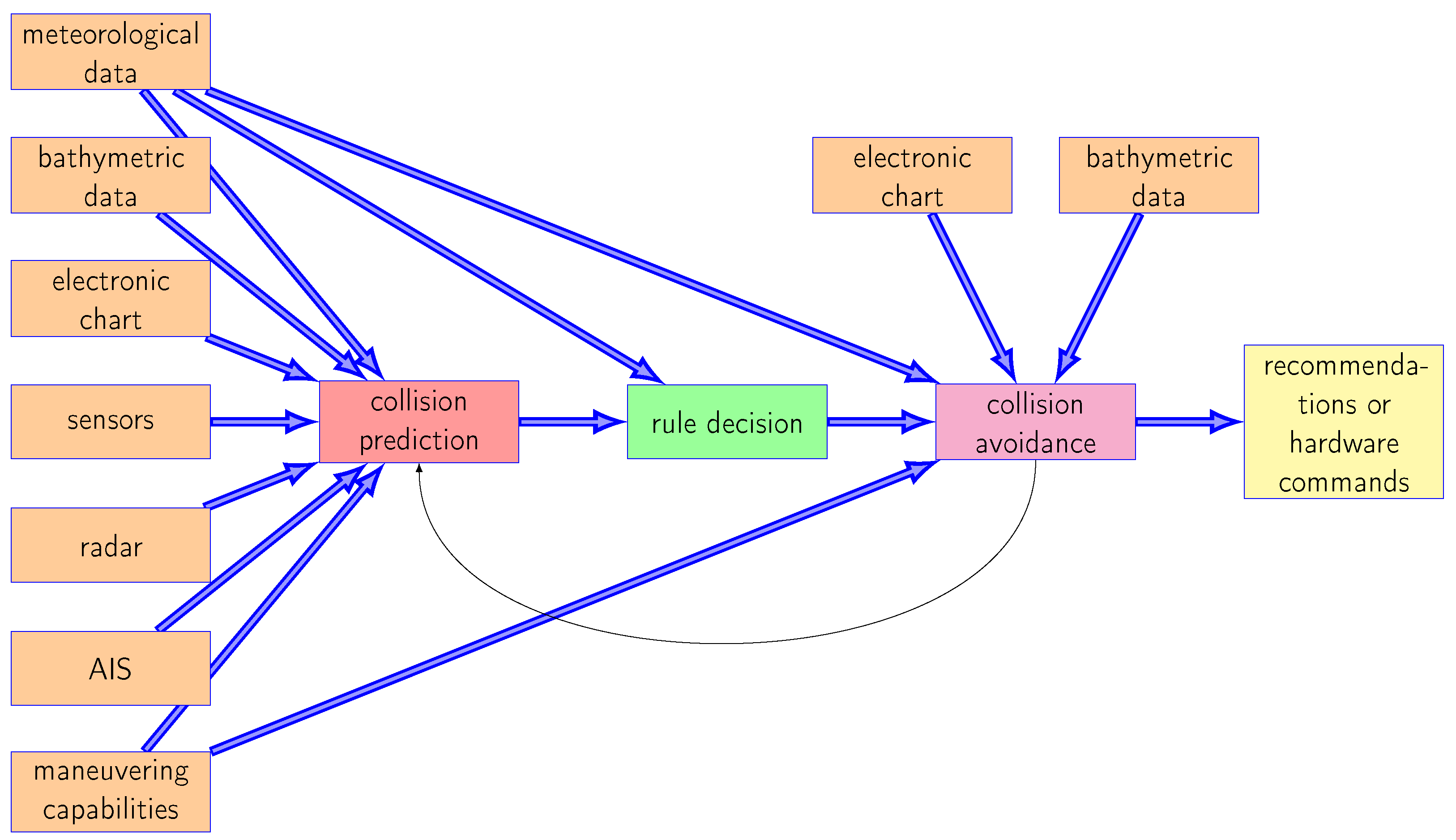
2. System Description

This section briefly presents the system in which the described Petri net is used.
The system presented is a collision avoidance system (CAS). Similar to other authors of such solutions (an example can be found in [14]), the system can generate suggestions for the commander and, in the future, could also generate direct commands for rudders and thrusters in the event of a collision threat. In addition to the functions of other system parts, the integration of the Petri net subsystem, described later, into the overall system is also described here. The overall system is shown in Figure 1.
The collision avoidance system in Figure 1 consists of three basic blocks: the collision prediction block, the rule decision block, and the collision avoidance block. The task of the collision prediction block is to predict the movement of ships based on manuevring capability data, meterological and bathymetric data, as well as data from radar, automatic identification systems (ATSs), and electronic chart systems. The next block is the rule decision block, which sets the rules for passing ships based on meteorological data and data from the collision prediction block. The collision avoidance block, based on ship maneuverability data and meteorological data, as well as data from electronic charts and bathymetric data, provides ships with recommendations for safe routes.
The collision prediction block in Figure 1 is also connected to various sensors, which include a camera to detect fog and distinguish day from night, and devices to measure speed, direction and depth. From various sources of information such as electronic charts, AIS data, meteorological information, and radar data, the collision prediction block calculates the most likely future ship position using various algorithms. This calculation is performed every 10 s for all vessels in the aquatorium under consideration. At these times, the future positions are calculated for the time interval ( t n o w , t n o w + 1800 s], again in 10 s increments.
The black points in Figure 2 are predicted position points on the same time grid, for picture densities that are not necessarily on the 10s grid described above. The distance between points depends on the ship speed over ground (SOG). In Figure 2, the speed of the ship marked with 2 is greater than the speed of the ship marked with 1. Depending on ship length, weather conditions and time distance to the predicted point, a safety radius is calculated for each ship for each predicted point. If two circles intersect at a future point in time, a potential collision hazard exists. In Figure 2, the red circles represent the future time point 7 and orange circles represent time point 9. The two orange circles for ships 1 and 2 intersect, so there is a collision hazard for ships 1 and 2 at time 9. In this way, information is obtained about the ships involved as well as the potential collision time and position. One of the time-dependent position prediction methods used in current development is shown in [15].
This information about possible collisions is now passed on to the block rule decision in Figure 1. This block is realized using the coloured Petri net discussed in this report, and data are transferred to and from the coloured Petri net via the mechanisms described in Section 6.
The idea of using coloured Petri nets to solve collision hazards originated in the airspace industry and is described in a rudimentary way in  [16,17].
In paper [18], the authors present an idea of how to integrate flight rules and aircraft capabilities in colored Petri net transitions to avoid collisions.
Inspired by all these ideas, we developed the presented solution for automatic rule selection in the presence of a collision risk in ship traffic.
In the presented solution, the Petri net only determines the rule according to which ships should cross to comply with international rules, and transmits this information to the collision avoidance block. The collision avoidance block calculates the course-change according to the rules recommended by the coloured Petri net presented in this paper. This calculation additionally considers various pieces of information stored in the database, such as nautical charts [19], bathymetric data, the ship’s manoeuvrability [6] and meteorological data, and makes a course-change recommendation to the officer or, in the case of unmanned navigation, directly to the helm and engines. The following sections offer various details of how the coloured Petri net was implemented in the system under development.

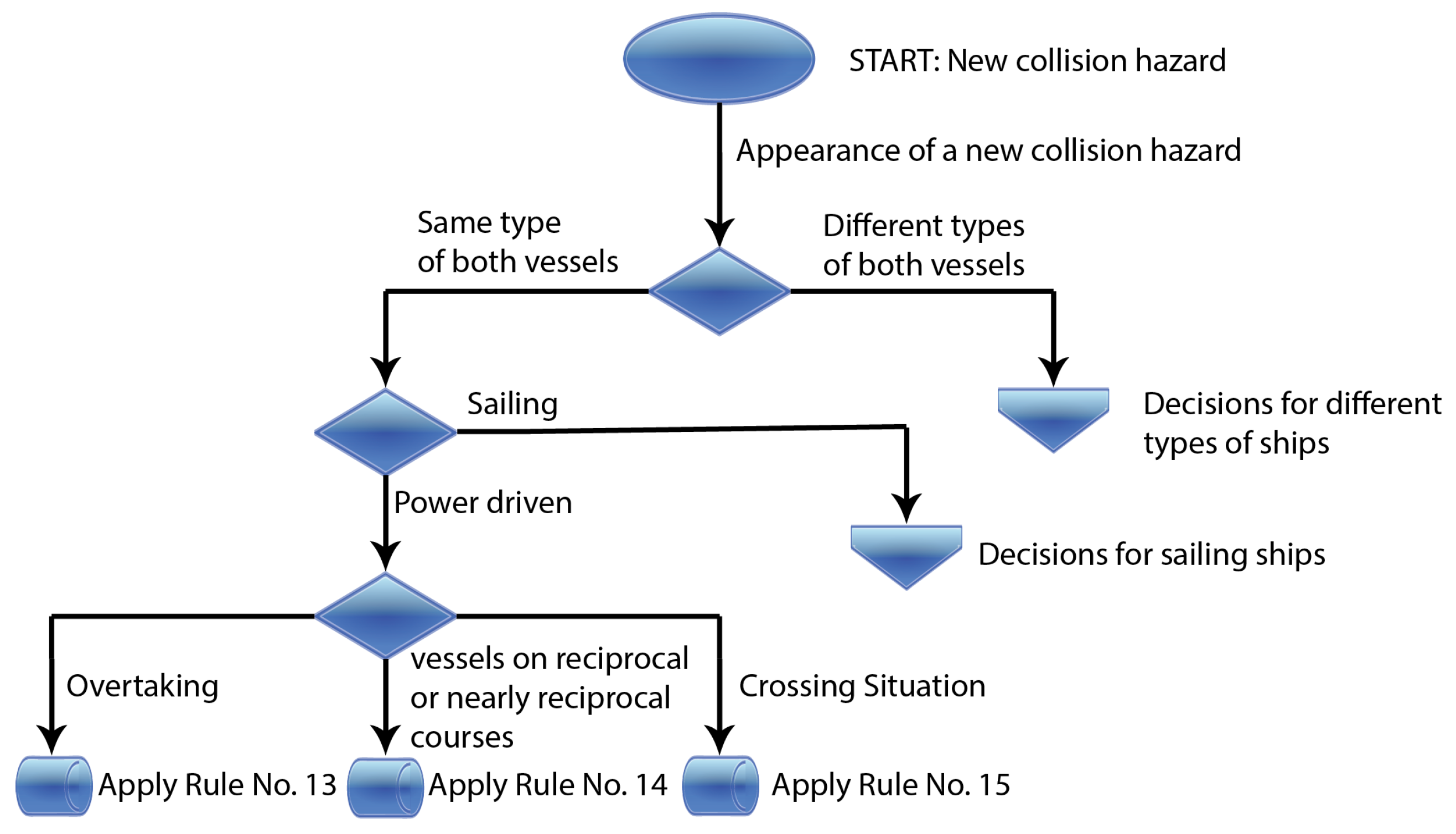
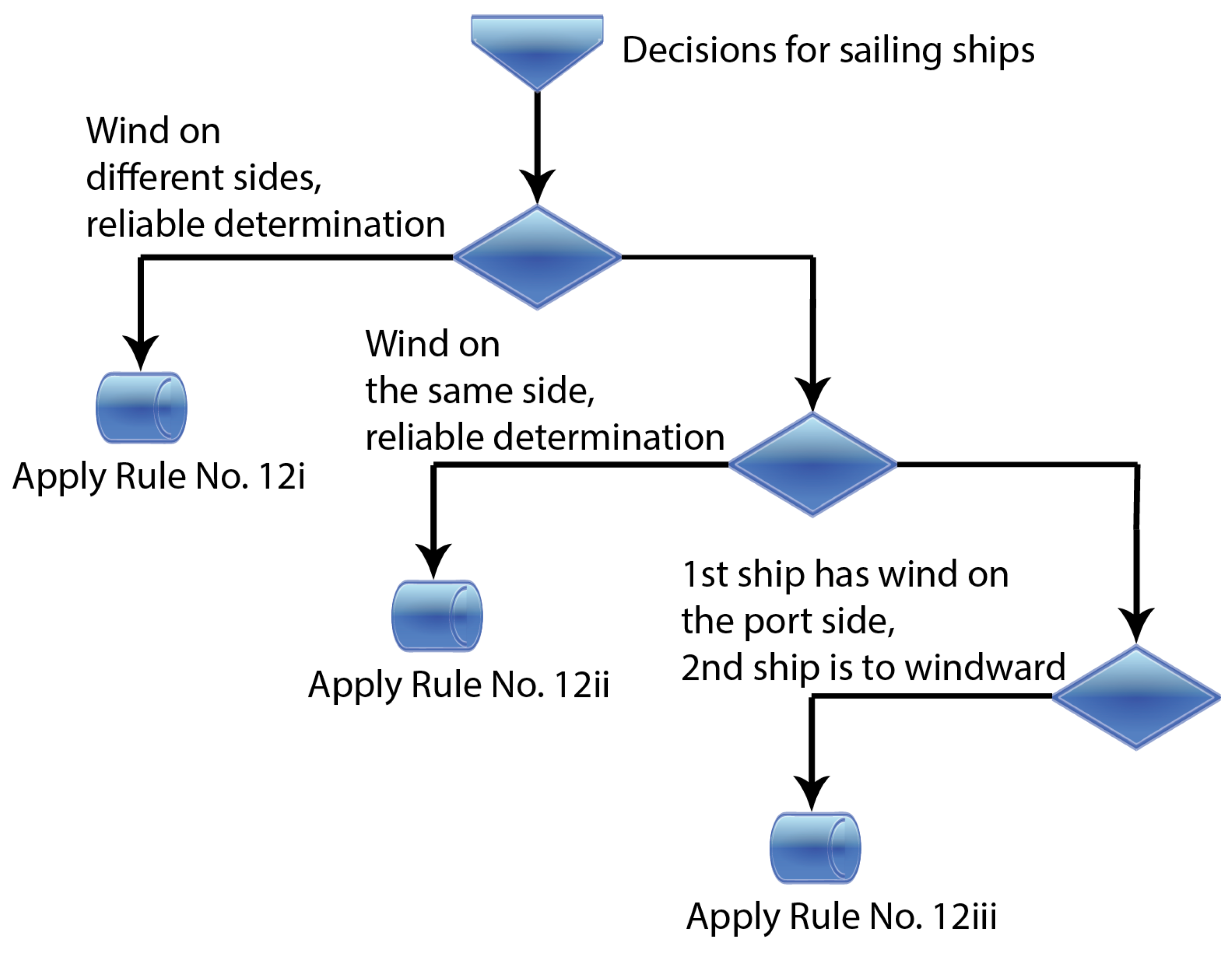
3. Rule Decision Block

If the risk of collision exists, the ships must perform their corrective movements according to certain rules. Such rules define the behavior of ships, for example, in situations when any vessel overtakes any other, when two power-driven vessels meet on reciprocal or nearly reciprocal courses or when two power-driven vessels are crossing in a way that involves risk of collision. The listed rules are certainly the best known of the many rules described in [13]. If there are two sailing ships in such a situation, the rules also consider the wind direction and relative wind direction of the ships involved (windward or not).
The function of the rule decision block is to select the rule that will be used in the given situation.
For illustration, part of the decision flow regarding the choice of rule to be applied by an officer in a typical situation is shown in Figure 3 and Figure 4.
Figure 3 shows part of the decision-making process for power-driven ships and Figure 4 shows part of the decision-making process for sailing ships.
As shown in Figure 3 and Figure 4, the result of the decision process is choice of the rule to be used. The decision-making process shown in the illustration is only the smallest part of the real decision-making process. The real decision-making process has more rules and more details to consider. We will present how the full COLREG compatible rule selection processes were realized. The resulting rule selection is then passed to the subsequent function block “collision avoidance” in Figure 1. This block then calculates the new ship routes based on the selected rule and other information, such as meteorological data, maneuvering capabilities of the ships, and electronic charts.

4. Coloured-Petri-Net-Based Rule Decision Block

The “Rule decision” presented in Figure 1 selects on of the rules described in the previous chapter, depending on the relative ship positions, type of ships, relative wind direction for sailing ships, etc. Colored Petri nets are used for this decision.
Coloured Petri nets are an extension of Petri nets and their mathematical fundamentals. They are backward-compatible with classical Petri nets and are described in [10,11,12].
Coloured Petri nets assign colours to tokens, allowing for them to be distinguished from each other. The token colour represents the assigned data value. This can be arbitrarily complex. Certain areas of coloured Petri nets contain a particular kind of colour, which is called the colour set of the place.
Formal definition of a coloured Petri net:
A coloured Petri net is a tuple N = ( P , T , A , Σ , C , N , E , G , I ).
  • P denotes a set of places.
  • T denotes a set of transitions.
  • A denotes a set of arcs.
  • Σ denotes a set of colour sets.
  • C denotes a colour function. The colour function describes the mapping between places in P and colours in Σ .
  • N denotes a node function. The node function describes the mapping between arcs in A and ( P  ×  T ) ∪ ( T  ×  P ).
  • E denotes an arc expression function. The node function describes the mapping between all arcs in A and their associated expressions.
  • G denotes a transition guard function. The node function describes the mapping between all transitions in T and the associated guard functions.
  • I denotes an initialization function. The initialization function describes the initialization of all places in P .
The following also applies in coloured Petri nets:
( P  ∩  T ) = ( P  ∩  A ) = ( T  ∩  A )
A colour set is a named collection of colours that an element can take. Colour, here, has a somewhat broader meaning, representing various properties.
In this case, for example, the colours in a colour set might be the following properties of a vessel: power_driven, sailing, engaged_in_fishing, etc.
This colour set of vessel properties is logically called VESSEL_TYPE in the present application.
A colour subset is a specific named group within a colour set. This group can often be characterised by some additional property. However, this is not a necessary condition for grouping colours in a subset.
In the present case, a colour subset RESTRICTED_IN_MANEOUVRE can be defined within the colour set VESSEL_TYPE. The following colours from the set VESSEL_TYPE then belong to this colour subset: Engaged_in_laying, Engaged_in_dredging, etc.
When colour sets are combined to describe multiple properties, we are talking about colour set products.
One example of such a product in our project is the colour set WIND. This is a product of the colour sets WIND_DIRECTION and WIND_SPEED. Both colour sets contain all real values. In our application, the colour of the wind is defined as a product of two colours, the first representing the direction and the second the speed.
A token in the coloured Petri net is a sequence of different elements. These single token elements can be simple members of the colour sets, but also arbitrarily complex sequences of other tokens. The nesting depth of the tokens can be arbitrarily deep.
An example of a token that consists of several other tokens is the token vessel_pair_1, which is used in our coloured Petri net. The value of this token comes from the colour space COLLISION_HAZARD_VESSEL_PAIR and this token is a concatenation of two tokens from the colour space VESSEL, the time of the possible collision and the wind. The token from the colour space VESSEL is, in turn, composed of a set of elements describing the ship. Consequently, the colour space VESSEL is a product of the following colour spaces: VESSEL_TYPE, MMSI, LENGTH, LONGITUDE, LATITUDE, COG, SOG, COR_COG, COR_SOG.
All the mentioned colour sets will be explained later in this article.
The places have the following inscriptions:
  • Name
  • A colour set is required. All tokens entering and leaving this place are from this colour set.
  • The initial marking defines the number and values of tokens that were initially in that location.
In CPN, tokens move from one place to another via transitions. In a transition, the token can be blocked, delayed, changed, and replaced with another type of token.
A transition can contain the following optional inscriptions:
  • Transition name
  • Guard
  • Time
  • Code segment
  • Priority
How the capabilities of each of these optional inscriptions of a transition are used in our network is explained later in this article.
Arcs connect places with transitions and transitions with places.
They have only one inscription, namely, an expression in the language ML. The result of this expression can be a multiset (multiple tokens) or just one token. The result can also be empty. In the latter case, the token no longer exists on this arc.
The use of arc inscriptions is described in Section 7. By means of the shown inscriptions, their powerful possibilities are demonstrated.
The language ML was developed in 1973 by Robin Milner at the University of Edinburgh. At present, it belongs to a family of programming languages that provide functional programming with rigorous evaluation. The best known member of this family is Standard ML. Functional programming makes it particularly easy to describe algorithms without considering the nature of the data objects being processed, resulting in a generic programme code. ML is now taught as the primary programming language at some universities. Good books for an introduction to programming and simultaneous connection to ML and its standard libraries are [9,20,21]. Some possibilities of this language are demonstrated here, along with examples.

5. Use of Coloured Petri Nets for Nautical Problems

In the presented CAS system, the selection of traffic rules is implemented with CPN. The traffic rules, whose selection is implemented with Coloured Petri Network, are described in [13].

5.1. Defined Colour Sets

To make the best use of all the possibilities of CPN in the model, a set of colour sets was defined.
All vessel types that can be found in [13] (p. 15) are included in the colour set VESSEL_TYPE. Consequently, this colour set has the following members:
  • Power_driven
  • Sailing
  • Engaged_in_fishing
  • Seaplane
  • Not_under_command
  • Engaged_in_laying
  • Engaged_in_dredging
  • Engaged_in_replenishment
  • Engaged_in_launching_or_recovery_of_airctaft
  • Engaged_in_mine_clearance
  • Engaged_in_towing
  • Constrained_by_draught
  • Otherwise_restricted
The colour set RESTRICTED_IN_MANOEUVRE is a subset of VESSEL_TYPE and has members from the list above, starting with the colour Engaged_in_laying and ending with the colour Otherwise_restricted.
The colour set VISIBILITY has only two members: Good_visibility and Fog.
The colour set WATERWAY has the following members:
  • Unrestricted.
  • Narrow_channel.
  • Traffic_separation_schema.
The colour set MMSI represents the unique identification value Maritime Mobile Service Identity (MMSI) from the AIS system. According to its definition, all integer values are members of this colour set.
The colour set COLLISION_HAZARD has only two members, appearance and cassation, depending on whether the collision hazard is new or no longer present.
The colour set COG corresponds to the COG value of the ship (e.g. from gyrocompass, GPS, etc., for own ship; from AIS, radar, etc., for other ships).
The colour set SOG corresponds to the SOG value of the ship.
The colour sets LONGITUDE and LATITUDE represent the longitude and latitude of the ship.
The colour set VESSEL_AISTYPE represents the ship type in the system AIS.
The colour sets TOBOW, TOSTERN, TOPORT, TOSTARBOARD, DRAUGHT and LENGTH represent the physical dimensions of the ship.
The colour sets WIND_SPEED and WIND_DIRECTION describe the speed and direction of the wind. The members of previous colour sets from COG to LATITUDE, and also DRAUGHT, WIND_SPEED and WIND_DIRECTION, are real numbers.
The members of other colour sets are integers.
The colour set COLLISION_TIME is the time at which a collision is expected if both ships continue their current motion. Integer values are members of this colour set.

5.2. Defined Colour Set Products

The colour set VESSEL describes the vessel and its movement and is a product of the colour sets VESSEL_TYPE, MMSI, LENGTH, LONGITUDE, LATITUDE, COG, SOG, COR_COG, COR_SOG.
The colour set WIND is a product of the colour sets WIND_DIRECTION and WIND_SPEED.
The colour set COLLISION_HAZARD_VESSEL is a product of the colour sets COLLISION_HAZARD, VESSEL, COLLISION_TIME, VISIBILITY and WATERWAY, and describes, as seen from our own ship, the risk of collision (appearance or cassation), the vessel with the potential collision risk, the expected time of collision, the visibility at sea, and the waterway policy in the affected area at sea.
The colour set COLLISION_HAZARD_VESSEL_PAIR is a product of the colour sets VESSEL, VESSEL, COLLISION_TIME, and WIND. Viewed from one’s own vessel, the first colour set VESSEL in this product describes one’s own vessel and the second colour set VESSEL describes the vessel with which there is a risk of collision. The colour set WIND in the product is used in rule selection when one or both ships are sailing ships.

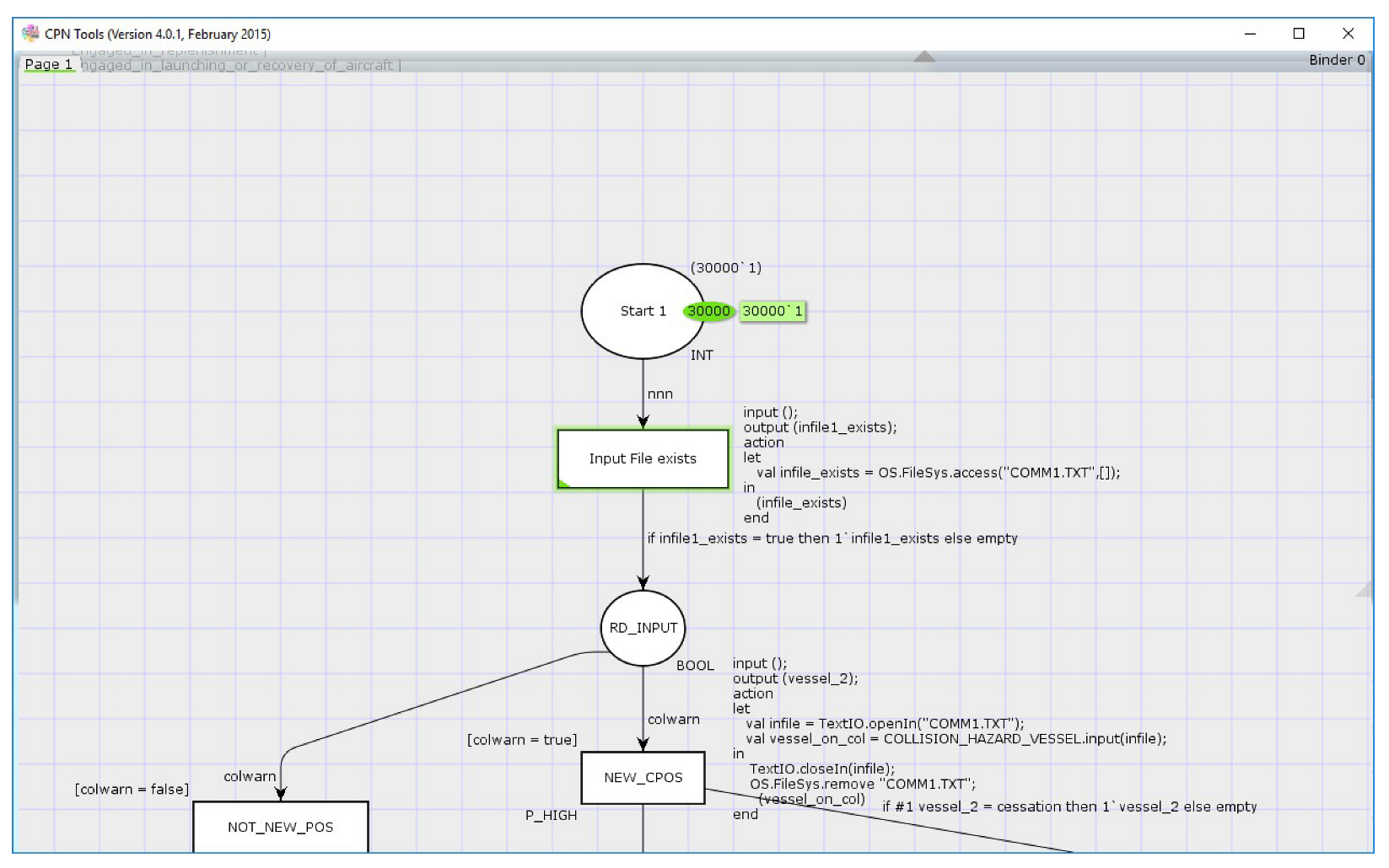
6. Connection between Real World and CP Network

At time intervals of 1s, the coulored Petri network checks whether the outside world has written a new file containing information about a possible collision. If the file exists, the information about the possible collision is read from the file as a token and the file is then deleted.
This procedure is presented in Figure 5.
The place named Start 1 has initial tokens from the colour set INT (integer). When the Petri net is activated, there are 30,000 tokens with colour 1 at this place at first. This number was chosen arbitrarily. With the start command, we tell the CPN tools that the net should be calculated at time intervals of 1 s.
Therefore, every second, a token leaves the Start 1 place and arrives in the transition called Input File exists. The ML code segment in this transition is started when the token arrives. The output token of the transition comes from the colour set BOOL (ean). The code segment generates the output token with the values true or false depending on whether a new file with a new hazard exists. This token now goes with the arc to the place RD_INPUT. The inscript of the arc says that if the token value is true, a token with that value goes on the place RD _INPUT. If the token value is false, the token disappears from the network before it reaches the place RD_INPUT. If a token reaches the place RD_INPUT, it leaves the place in the direction of the transition NEW_CPOS. In the code segment of this transition, the externally generated file COMM1.TXT can be opened and read because it exists.

6.1. Input File comm1.txt with Information about the Possible Collision

This file was created within the collision prediction part of the system, as shown in Figure 1.
An example of the file with the impending collision entry is:
(appearance, (Power_driven, 21113, 28, 16.3755223471, 43.42413552545, 111.25, 12.2325, 0, 0), 627)
The line has the following meaning:
A new collision risk was established with the ship with VESSEL_TYPE Power_driven, with identifier mmsi equal to 21113, and a ship length of 28 m, on coordinates (16.3755223471, 43.42413552545), with course over ground 111.25° and speed over ground 12.2325 knots. The expected time until collision was 627 s. This vessel described in this file is the second of vessels involved in the risk of a possible collision.

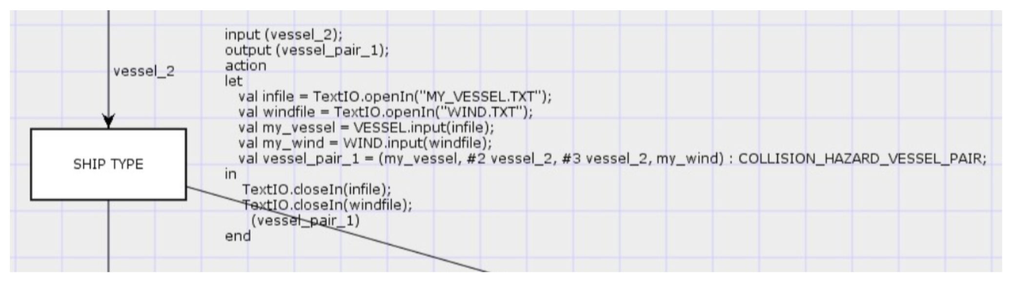
6.2. Input File with Information about 1st Vessel Involved

This file contains information about the first vessel involved in collision risk in case of an external collision avoidance system or about one’s own vessel if the collision avoidance system is installed on the vessel itself, and is called my_vessel.txt.
An example of this file is as follows:
(Power_driven, 11113, 27, 16.4240552321, 43.3797230245, 3.45, 15.3, 0, 0)
The line has the following meaning:
The colour VESSEL_TYPE is Power_driven, mmsi 11113, length 27 m, current coordinates (16.4240552321, 43.3797230245), course over ground 3.45° and speed over ground 15.3 knots.
The corrected COG and SOG (COR_COG and COR_SOG ) are both still 0.0 because no corrective actions have been calculated yet.

6.3. Input File with Information about Wind

The file with the information about the wind is called wind.txt.
An example of the file is as follows:
(145, 13.4)
The line has the following meaning:
The wind from the colour space WIND has the direction from the colour set WIND_DIRECTION with the value 145° and the speed from the colour space WIND_SPEED with the value 13.4 m/s.

6.4. Output File with Information about Corrective Action

The required corrective action is communicated to the subsequent “collision avoidance” system part in Figure 1 via the REQ_ACTION.txt file. This file is generated by the coloured Petri net. The transitions in which this happens correspond to the output blocks in Figure 3 and Figure 4.
The file has three lines with the following content:
The first line contains the rule to be applied and the ship that should change its course.
The second line has the following content:
C: Number of course-correcting ships (1 or 2) MMSI: mmsi of the first ship (MMSI: mmsi of the second ship)
The third line contains the color value COLLISION_HAZARD_VESSEL_PAIR.
An example of this file is as follows:
Rule 15 2nd ship
C: 1 MMSI: 21113
((Power_driven, 11113, 27, 16.4240552321, 43.3797230245, 3.45, 15.3, 0, 0), (Power_driven, 21113, 28, 16.3755223471, 43.42413552545, 111.25,12.2325, 0, 0), 627, ( 145.0, 13.4))

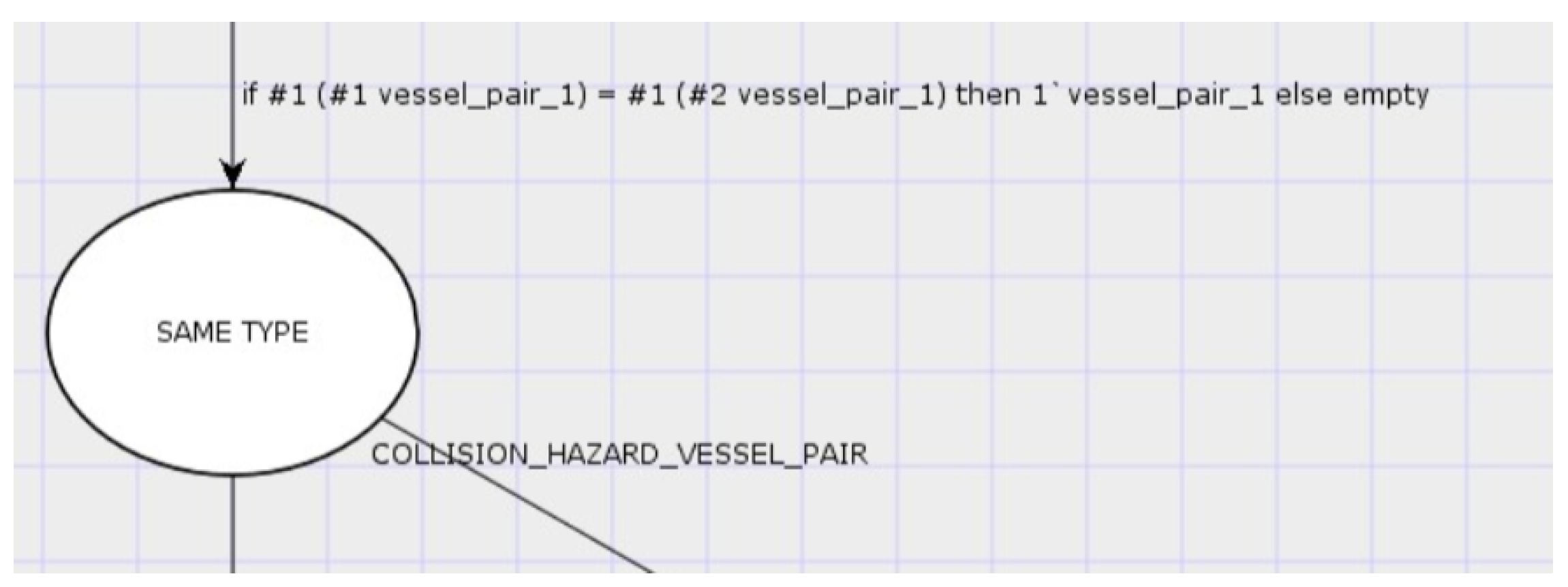
7. Use of Arcs and Transitions

Arcs connect places with transitions and transitions with places and transport tokens. Several arcs can start from a place as well as from a transition. A token leaving a place or transition appears simultaneously on all arcs starting from this place or transition. Transition inscription is a logical operation written in ML on colors of the token, and its result is true or false. Depending on this result, the token can be repeated many times on the affected arc, forwarded individually or removed from the network.
In the presented application, the operations with the colors of the tokens are used to decide which nautical rule should be applied in a given situation.
An ML inscription that checks whether both ships involved in a collision hazard are of the same type according to the previous color product definitions in Section 5.2 is shown in Figure 6.
The following explanation applies to Figure 6: All CPN tokens transported to and from the place SAME TYPE have the color from the color product space COLLISION_HAZARD_VESSEL_PAIR. The token on the arc has the designation vessel_pair_1. The inscription on the arc to the place SAME TYPE can be read in the following manner: If the first color of the first product component is equal to the first color of the second product component, then the token vessel_pair_1 is transported further to the place; otherwise, the token disappears from the network. The first product component in the color product space COLLISION_HAZARD_VESSEL_PAIR is from the product space VESSEL, as defined in Section 5.2, and the first color from this color space product is VESSEL_TYPE, so that the inscription describes the following condition: If the type of the first vessel is equal to the type of the second vessel, then the token is transported to the place SAME TYPE.
Transitions can execute arbitrarily complex ML code segments in which files can be read and written. The color values of the input token can be changed and new tokens can be created. A transition from the presented network is shown, along with the corresponding ML code, in Figure 7. In this transition, a token is created with the color values read from the file. The color of the created token is taken from the color product space COLLISION_HAZARD_VESSEL_PAIR.
Optional guards can be placed at the transition entrances. These are logical operations on token colors, and the token is only let into the transition if a true result is obtained. A guard that only grants the token entrance into the transitio if the color VESSEL_TYPE of the first ship has the color value Power_driven and the color VESSEL_TYPE of the second ship has the value Sailing can be seen in Figure 8.
Finally, after the tokens have migrated through the network with the described mechanisms to the correct place representing the rule that is to be applied, the values (colors, place, etc.) of the downstream system part must be written to a file. This happens again in a transition and tis shown in Figure 9.
Here, it must be emphasized that the whole of the coloured Petri net with all inscriptions is built in such a way that, in case of a collision hazard, only one token from the color product COLLISION_HAZARD_VESSEL_PAIR reaches only one place representing the rule to be applied.

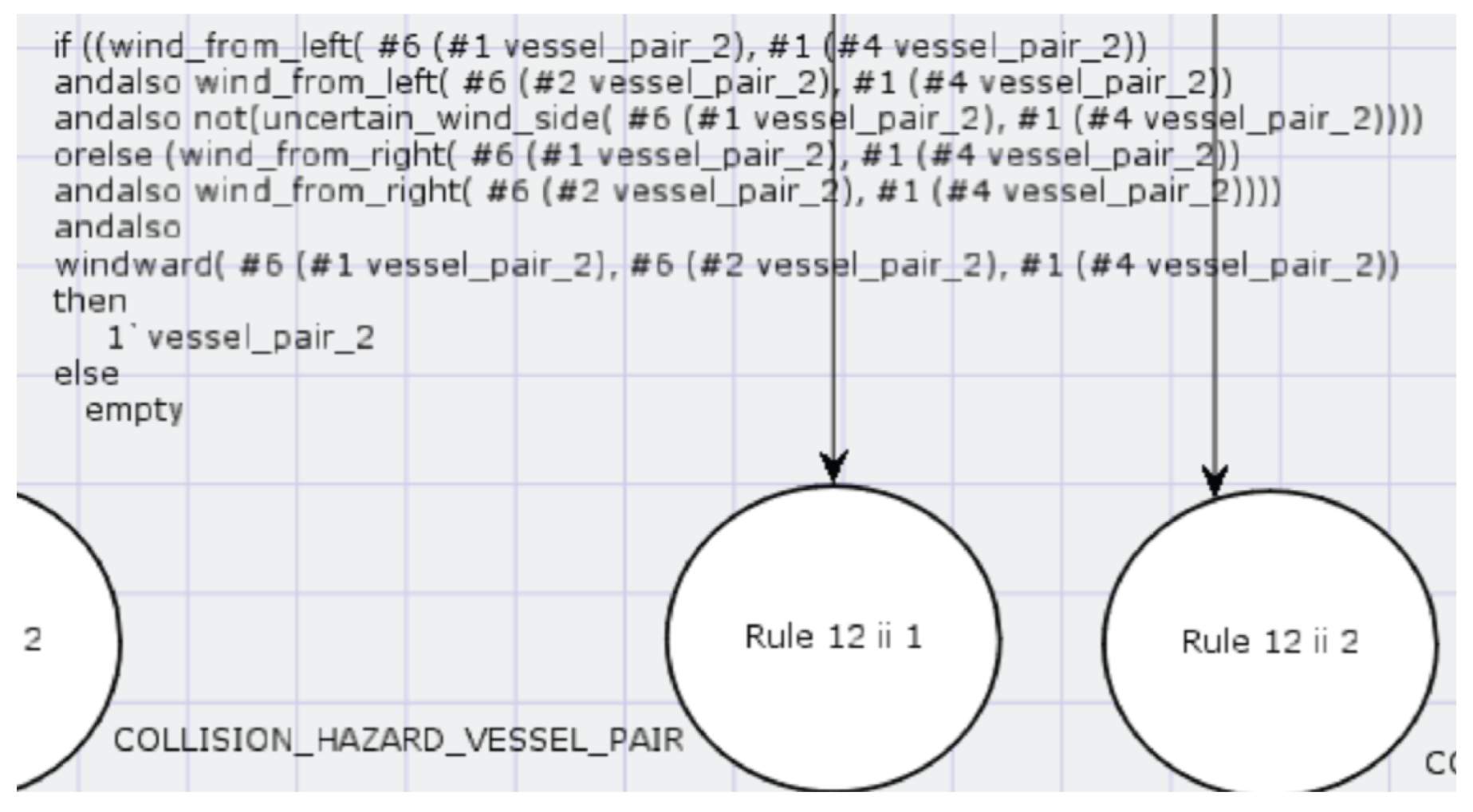
8. Use of User-Defined ML Functions in Arc Inscriptions

Having explained the previous sections how the simple arithmetic and comparison operations of colours can be used in inscriptions, this section explains how user-defined ML functions can be used in inscriptions. The rules for sailing ships passing each other are described in [13] (p. 39). Deciding which of the given rules (12i, 12ii, 12iii) to apply is a bit more complicated, and requires three ML functions. The functions estimate whether the sailing ship has the wind from the left (wind_from_left), and this estimate is certain, while it is not certain that the other ship has the wind from the left (wind_from_left_unsure), or whether the ship is windward (windward).
All these functions return a single logical value true or false as a result. The two arguments of all these functions, namely the ship’s course and the wind direction, are the same.
The wind direction in Figure 10 is given by
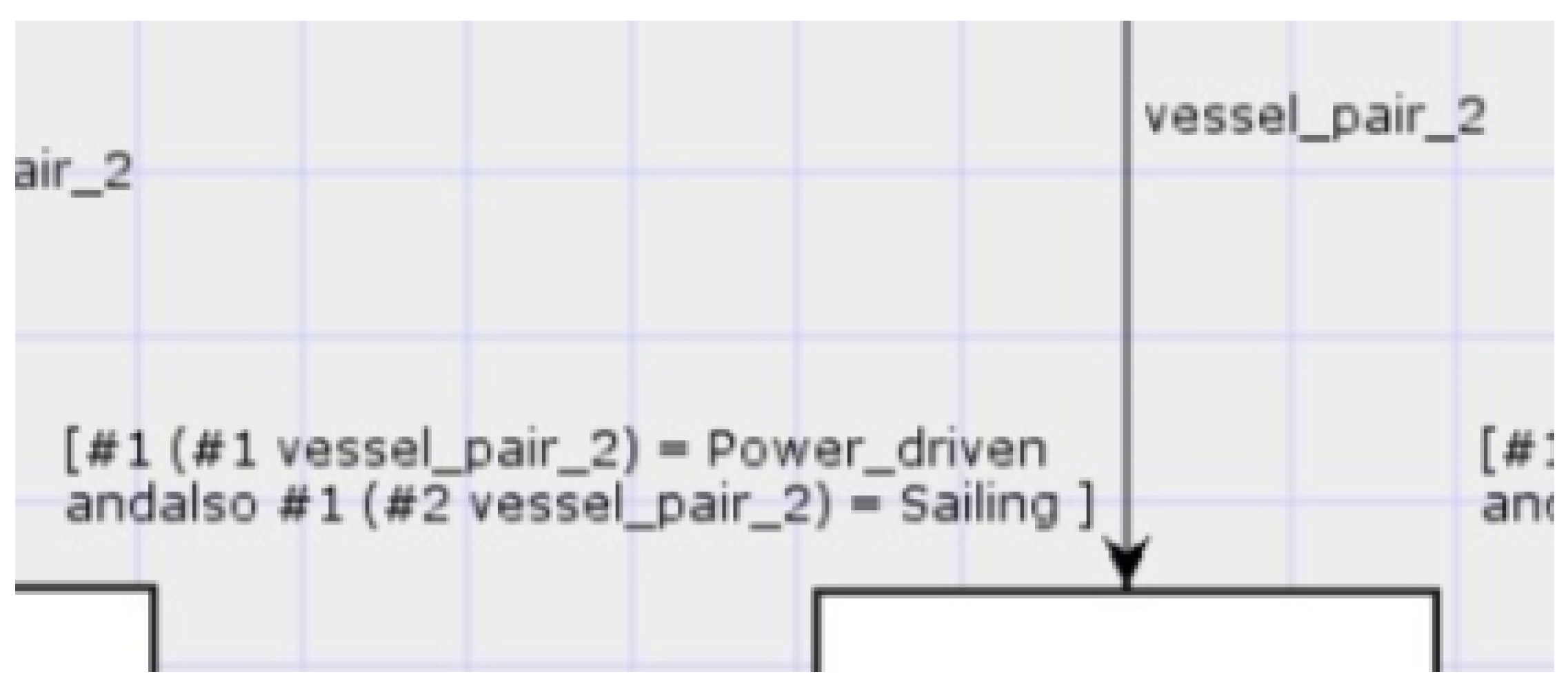
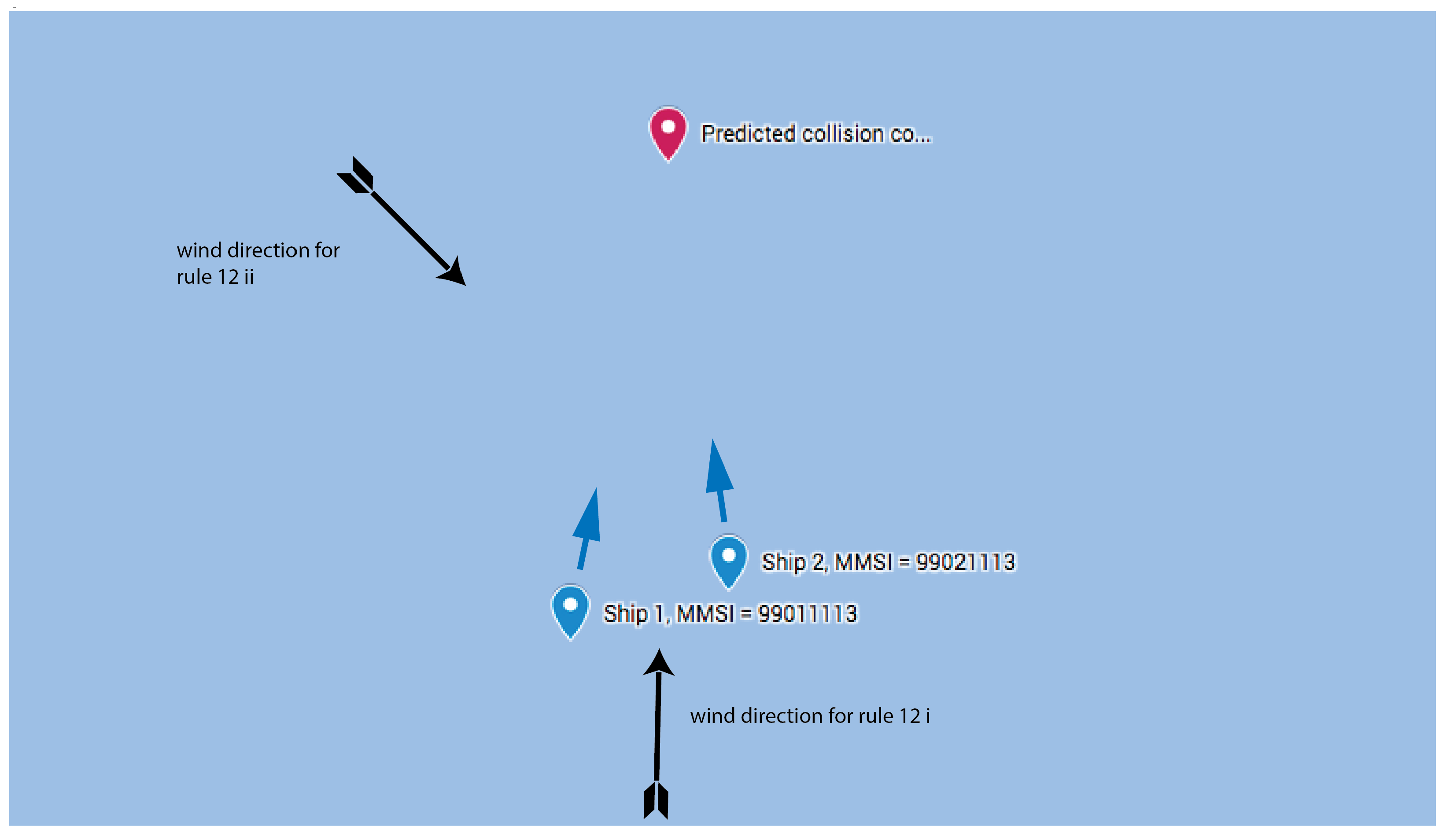
  • #1 (#4 vessel_pair_2), according to the definitions of the colour sets in Section 5.2. The used function wind_from_left returns true if the wind comes from the left side of the ship. The direction of the first ship is given by
  • #6 (#1 vessel_pair_2), according to the definition of the colour sets in Section 5.2. The direction of the second ship is given by
  • #6 (#2 vessel_pair_2). The token vessel_pair_2 colour value comes from the colour set COLLISION _HAZARD _VESSEL _PAIR.
The ML definition of the functions is explained in the following.
In the angular relations between wind and ship, according to the definition of all these functions, it is important to treat the transition between 360° and 0° correctly. As a first example, it is assumed that the ship has a course of 10°. The direction in which the wind blows is indicated in the wind data: in this case, all winds blowing in directions 10° to 190° come from the left. In the second example, if the ship has a course of 190°, then all winds blowing in the directions 190° to 360° and 0° to 10° come from the left. According to these two examples, it is easy to read and understand the ML definition of the function wind_from_left given below (Listing 1).
Figure 10. CPN tools, Arc inscriptions with ML functions. Source: Authors.
Jmse 11 01322 g010
Listing 1. CPN Tools, Definition of the fuction wind_from_left.
fun wind_from_left(v1: REAL, v2: REAL) =
         let
                 val from_left = false ;
         in
                 if v1 < 180.0
                          then
                                   if v2 > v1 andalso v2 < (v1 + 180.0)
                                            then
                                                     true
                                            else
                                                     false
                          else
                                   if v2 > v1
                                            then
                                                     true
                                            else
                                                     if v2 < (v1 - 180.0)
                                                              then
                                                                         true
                                                              else
                                                                         false
end;
The next example explains the ML windward function. This function has three arguments: course of the first ship, course of the second ship and the wind direction. For an explanation of this function, we first look at the Figure 11.
Two sailing ships are on a collision course. The courses of both ships are given by α 1 and α 2 . Both ships have wind with a direction α 3 from the same (right) side and the function windward can be used to determine whether the first or the second ship are windward.
Geometric observations show that the angle β i between the ship’s course α i and the wind direction α 3 is smaller for the windward ship than for the leeward ship. This fact provides the basis for the windward function.
The ML function windward (COG ship 1, COG ship 2, winddirection) returns the value true if the shiff 1 is windward and false otherwise. The code for this ML function is shown in the following Listing 2.
Listing 2. CPN Tools, Definition of the fuction wind_from_left.
fun windward(v1: REAL, v2: REAL, v3: REAL) =
  let
    val first_ship_winward = false ;
  in
    if abs(v1 - v3) < 180.0
      then
        if abs(v2 - v3) < 180.0
          then
            if abs(v1 - v3) < abs(v2 - v3)
              then
                   true
              else
                   false
          else
            if abs(v1 - v3) < abs(360.0 - abs(v2 - v3))
              then
                true
              else
                false
      else
        if abs(v2 - v3) < 180.0
          then
            if abs(360.0 - abs(v1 - v3)) < abs(v2 - v3)
              then
                true
              else
                false
          else
            if abs(360.0 - abs(v1 - v3)) < abs(360.0 - abs(v2 - v3))
              then
                true
              else
                false
end;
The ML code is easy to read and is not explained in detail.

9. Test Method

The presented subsystem was tested by being fed with different file pairs comm1.txt and my_vessel.txt, as described in Section 6.1 and Section 6.2, and the wind.txt file described in Section 6.3. Then, an analysis was conducted to see which [13] rule was chosen by the described subsystem in each case. This information was provided via an output file REQ_ACTION.txt, as described in Section 6.4, to the “Collision Avoidance” block in Figure 1. All mentioned input file pairs, which serve as test vectors for the presented subsystem, were generated manually for different ship types and relative ship directions. If at least one vessel in the generated testpairs was a sailing vessel, different wind directions with 10° increments were also considered in the generated testpairs. The subsystem-forming colored Petri net was repeatedly adjusted until all generated test pairs produced the expected results.
The PostGIS function ST_Project was used for the calculation of the test pair data for the so-called geodetic problem on the spheroid (calculating the coordinates of the second point from the coordinates of the first point, and the distance and direction to the second point). Detailed information about the Postgres database software and about the PostGIS extension of this software can be found in [22,23].

10. Results

Some test input files with corresponding result files are presented in this section. The content of the input test files is always given in the following order: one line per file: ship 1 (file my_vessel.txt), collision danger (file comm1.txt), wind (file wind.txt). The subsystem finds the rule to be applied and specifies which vessel should make the course-correction.

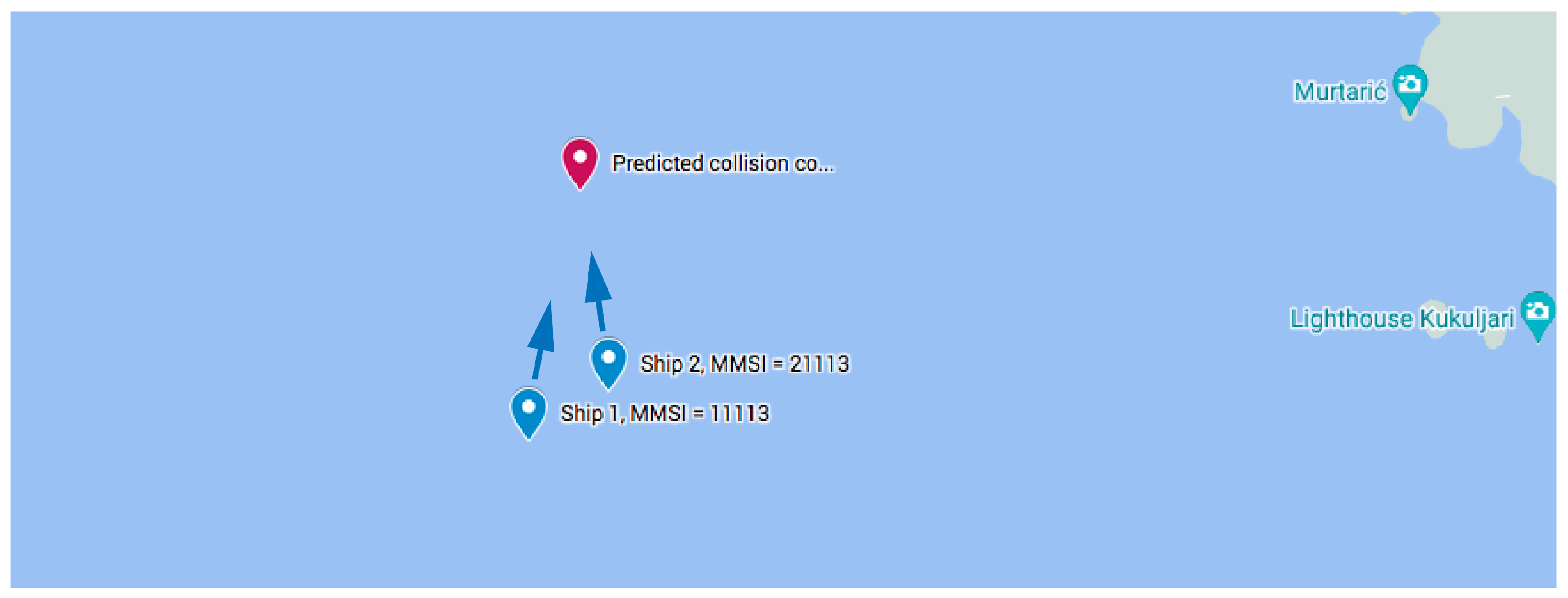
10.1. Two Power-Driven Ships

Here, we present the situations in which rules 15 (Crossing), 14 (Head-on) and 13 (Overtaking) were applied in the case of a collision risk between two power-driven ships.
The first example is the crossing situation with two ships: the first with the mmsi = 11,113 and the second with the mmsi = 21,113, as shown in Figure 12. The collision coordinates calculated by the collision prediction block with unchanged driving are (15.541289405362287, 43.770646738684405), and are reached in 227 s.
  • Input Informations from collision prediction block to the presented subsystem:
(Power_driven, 11113, 25, 15.536375690030786, 43.753137665718974, 11.5, 17, 0.0, 0.0)
(appearance, ( Power_driven, 21113, 30, 15.5440821521227, 43.75660275884937, 351.8, 13.5, 0.0, 0.0 ), 227, Good_visibility, Unrestricted )
(135, 13.4)
  • Output Information from the presented subsystem:
Rule 15 1st ship
C: 1 MMSI: 11113
((Power_driven, 11113, 25, 15.53637569, 43.7531376657, 11.5, 17.0, 0.0, 0.0), (Power_driven, 21113, 30, 15.5440821521, 43.7566027588, 351.8, 13.5, 0.0, 0.0), 227, (135.0, 13.4))
The second example is the overtaking situation with two ships: the first with the mmsi = 11,113 and the second with the mmsi = 21,113, as shown in Figure 13. The collision coordinates calculated by the collision prediction block with unchanged driving are (15.541289405362287, 43.770646738684405), and are reached in 227 s.
  • Information input to the presented subsystem:
(Power_driven, 11113, 25, 15.536375690030786, 43.753137665718974, 11.5, 17, 0.0, 0.0)
(appearance, (Power_driven, 21113, 30, 15.538430347642606, 43.756609907034296, 8.4, 13.5, 0.0, 0.0), 227, Good_visibility, Unrestricted)
(135, 13.4)
  • Information output from the presented subsystem:
Rule 13 1st ship
C: 1 MMSI: 11113
((Power_driven, 11113, 25, 15.53637569, 43.7531376657, 11.5, 17.0, 0.0, 0.0), (Power_driven, 21113, 30, 15.5384303476, 43.756609907, 8.4, 13.5, 0.0, 0.0), 227, (135.0, 13.4))
The third example is a head-on situation with two ships: the first with the mmsi = 11,113 and the second with the mmsi = 21,113, as shown in Figure 14. The collision coordinates calculated by the collision prediction block with unchanged driving are (15.541289405362287, 43.770646738684405), and are reached in 227 s.
  • Information input to the presented subsystem:
(Power_driven, 11113, 25, 15.536375690030786, 43.753137665718974, 11.5, 17, 0.0, 0.0)
(appearance, (Power_driven, 21113, 30, 15.544151107504057, 43.78468360058434, 188.4, 13.5, 0.0, 0.0), 227, Good_visibility, Unrestricted)
(135, 13.4)
  • Information output from the presented subsystem:
Rule 14 both ships
C: 2 MMSI: 11113 MMSI: 21113
((Power_driven,11113, 25, 15.53637569, 43.7531376657, 11.5, 17.0, 0.0, 0.0), (Power_driven, 21113, 30, 15.5441511075, 43.7846836006, 188.4, 13.5, 0.0, 0.0), 227, (135.0, 13.4))
Note that, in the subsystem output in lines 1 and 2 in this example, corrective action is required for both ships.

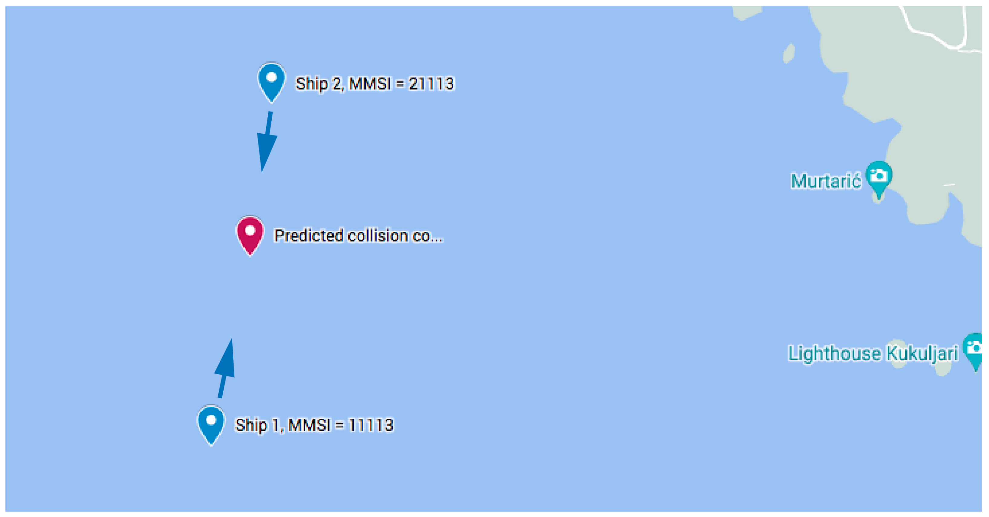
10.2. Two Sailing Ships

Here, the situations for the application of the rules 12 ii (wind on the same side) and 12 i (wind on a different side) are presented in the case of a risk of collision between two sailing ships.
The course and speed of sailing ship 1 are the same in both of the following examples. Likewise, sailing ship 2 has the same course and speed in both examples. The only difference between the examples is the wind direction. The examples aim to show how the wind direction is taken into account in the rule selection.
The position and sailing directions of the two sailing ships can be seen in Figure 15 In the same figure, the two wind directions, one for rule 12 ii and the second for rule 12 i, are drawn. The collision coordinates calculated by the Collision Prediction block with unchanged driving are (15.541289405362287, 43.770646738684405), and are reached in 127 s.
  • Information input to the presented subsystem:
(Sailing, 99011113, 15, 15.540157678618506, 43.76661323971328, 11.5, 7, 0.0, 0.0)
(appearance, (Sailing, 99021113, 14, 15.542007590544342, 43.7670383052422, 351.8, 6.2, 0.0, 0.0), 127, Good_visibility, Unrestricted)
(135, 13.4)
  • Information output from the presented subsystem:
Rule 12 ii 1st ship
C: 1 MMSI: 99011113
((Sailing, 99011113, 15, 15.5401576786, 43.7666132397, 11.5, 7.0, 0.0, 0.0), (Sailing, 99021113, 14, 15.5420075905, 43.7670383052, 351.8, 6.2, 0.0, 0.0), 127, (135.0, 13.4))
  • Information input to the presented subsystem:
(Sailing, 99011113, 15, 15.540157678618506, 43.76661323971328, 11.5, 7, 0.0, 0.0)
(appearance, (Sailing, 99021113, 14, 15.542007590544342, 43.7670383052422, 351.8, 6.2, 0.0, 0.0), 127, Good_visibility, Unrestricted)
(1.2, 13.4)
  • Information output from the presented subsystem:
Rule 12 i 2nd ship
C: 1 MMSI: 99021113
((Sailing, 99011113, 15, 15.5401576786, 43.7666132397, 11.5, 7.0, 0.0, 0.0), (Sailing, 99021113, 14, 15.5420075905, 43.7670383052, 351.8, 6.2, 0.0, 0.0), 127, (1.2, 13.4))

11. Conclusions

The article presents the rules for avoiding collisions at sea, which were implemented in a computer using a coloured Petri net. The charm of the presented implementation of the navigation rules is that the presented structures are clear and the implementation can be easily checked, even by people who are not software specialists. Moreover, the implementation can be easily extended with new rules at any time.
The described coloured Petri net was implemented and verified using CPN tools. The presented implementation allowed for multiple simulations of the behaviour under different necessary manoeuvres, as well as integration into a real system. With the hardware platform (a normal PC with 2.8 GHz and multiple cores) used for CPN Tools, a time resolution of less than 1s was achieved in the real system, which can be considered sufficient for autonomous navigation decision processes. The next step in the implementation may be an automatic translation of the presented network into a language that allows for its operation in an embedded system. With this step, the complete integration of the network presented in Section 2 into a single embedded system may be possible.

Author Contributions

Conceptualization, V.B., D.K. and R.B.; methodology, V.B., D.K., R.B. and S.K.; software, V.B. and D.K.; validation, V.B., D.K., R.B. and S.K.; formal analysis, V.B. and R.B.; investigation, V.B., D.K., R.B. and S.K.; resources, V.B., R.B., D.K. and S.K.; data curation, V.B., R.B., D.K. and S.K.; writing—original draft preparation, V.B.; writing—review and editing, R.B., D.K. and S.K.; visualization, V.B.; supervision, D.K. and R.B.; project administration, S.K. All authors have read and agreed to the published version of the manuscript.

Funding

This research received no external funding.

Institutional Review Board Statement

Not applicable.

Informed Consent Statement

Not applicable.

Data Availability Statement

No datasets available.

Conflicts of Interest

The authors declare no conflict of interest.

References

  1. Sun, T.; Liu, C.; Xu, S.; Hu, Q.; Li, C. COLREGS-Complied Automatic Collision Avoidance for the Encounter Situations of Multiple Vessels. J. Mar. Sci. Eng. 2022, 10, 1688. [Google Scholar] [CrossRef]
  2. International Maritime Organization (IMO). COLREG—Preventing Collisions at Sea. Available online: https://www.imo.org/en/OurWork/Safety/Pages/Preventing-Collisions.aspx (accessed on 10 May 2023).
  3. Heiberg, A.; Larsen, T.N.; Meyer, E.; Rasheed, A.; San, O.; Varagnolo, D. Risk-based implementation of COLREGs for autonomous surface vehicles using deep reinforcement learning. Neural Netw. 2022, 152, 17–33. [Google Scholar] [CrossRef] [PubMed]
  4. Hansen, P.N.; Papageorgiou, D.; Blanke, M.; Galeazzi, R.; Lützen, M.; Mogensen, J.; Bennedsen, M.; Hansed, D. COLREGs-based Situation Awareness for Marine Vessels—A Discrete Event Systems Approach. IFAC-PapersOnLine 2020, 53, 14501–14508. [Google Scholar] [CrossRef]
  5. International Hydrographic Oganization. S-100 Specification Numbers. 2020. Available online: http://s100.iho.int/S100/home/s-100-specification-numbers (accessed on 1 March 2022).
  6. Brozović, V.; Bošnjak, R.; Kezić, D.; Brozović, F. Storage of the Ship maneuvering Capabilities into the Postgres Database. In Proceedings of the ICTS2022, Portotoz, Slovenia, 23–24 May 2022; pp. 69–75, ISBN 978-961-7041-11-8. [Google Scholar]
  7. Lyu, H.; Yin, Y. Ship’s trajectory planning for collision avoidance at sea based on modified artificial potential field. In Proceedings of the 2017 2nd International Conference on Robotics and Automation Engineering (ICRAE), Shanghai, China, 29–31 December 2017. [Google Scholar] [CrossRef]
  8. Huang, Y.; Chen, L.; Chen, P.; Negenborni, R.R.; van Gelder, P.H.A.J.M. Ship collision avoidance methods: State-of-the-art. Saf. Sci. 2020, 121, 451–473. [Google Scholar] [CrossRef]
  9. Gansner, E.R.; Reppy, J.H. The Standard ML Basis Manual; Cambridge University Press: Cambridge, UK, 2004; ISBN 978-0-521-79478-7. [Google Scholar]
  10. Jensen, K. Coloured Petri Nets—Basic Concepts, Analysis Methods and Practical Use; Springer Science & Business Media: Berlin/Heidelberg, Germany, 2013; Volume 1, ISBN 978-3-662-03241-1. [Google Scholar]
  11. Jensen, K. Coloured Petri Nets—Basic Concepts, Analysis Methods, and Practical Use; Springer: Berlin/Heidelberg, Germany, 1997; Volume 2, ISBN 978-0-387-58276-4. [Google Scholar]
  12. Jensen, K. Coloured Petri Nets—Basic Concepts, Analysis Methods and Practical Use; Springer Science & Business Media: Berlin/Heidelberg, Germany, 2012; Volume 3, ISBN 978-3-642-60794-3. [Google Scholar]
  13. Jašić, D.; Belamarić, G.; Gundić, A. International Regulations for Preventing Collisions at Sea = Međunarodna Pravila o Izbjegavanju Sudara na Moru; Sveučilište u Zadru, Pomorski Odjel: Zadar, Croatia, 2011; ISBN 978-953-331-000-8. [Google Scholar]
  14. Huang, Y.; Chen, L.; Negenborni, R.R.; va Gelder, P.H.A.J.M. A ship collision avoidance system for human-machine cooperating during collision avoidance. Ocean Eng. 2020, 217, 107913. [Google Scholar] [CrossRef]
  15. Brozović, V.; Bošnjak, R.; Kezić, D.; Vojović, I. Real Time Prediction of the Ship Position with the PostGIS Function ST_PROJECT. In Proceedings of the ICTS2022, Portotoz, Slovenia, 23–24 May 2022; pp. 76–81, ISBN 978-961-7041-11-8. [Google Scholar]
  16. Shmelova, T.; Sikirda, Y.; Rizun, N.; Kucherov, D.; Dergachov, K. Automated Systems in the Aviation and Aerospace Industries; IGI Global: Hershey, PA, USA, 2019; ISBN 978-1-522-57710-2. [Google Scholar]
  17. Shmelova, T.; Sikirda, Y.; Sterenharz, A. Artificial Intelligence Applications in the Aviation and Aerospace Industries; IGI Global: Hershey, PA, USA, 2019; ISBN 978-1-799-81417-7. [Google Scholar]
  18. Piera, M.A.; Radanovic, M.; Leal, X. Multi-agent systems for air traffic conflicts resolution by using a causal analysis of spatio-temporal interdependencies. In Proceedings of the SCSC 2016, Montreal, QC, Canada, 24–27 July 2016; pp. 1–8, ISBN 978-1-5108-2424-9. [Google Scholar]
  19. Brozović, V.; Bošnjak, R.; Kezić, D.; Bojić, F. S-101 charts, Database Tables for S-101 charts, Autonomous Vessel. In Proceedings of the IMSC 2021, Varna, Bulgaria, 9–10 September 2021; pp. 26–35. [Google Scholar] [CrossRef]
  20. Smolka, G. Programmierung—Eine Einführung in die Informatik Mit Standard ML; Oldenbourg Wissenschaftsverlag GmbH: Munich, Germany, 2008; ISBN 978-3-486-58601-5. [Google Scholar]
  21. Hansen, M.R.; Rischel, H. Introduction to Programmierung Using SML; Pearson Education Limited: London, UK, 1999; ISBN 0-201-39820-6. [Google Scholar]
  22. The PostgreSQL Global Development Group. PostgreSQL 14.1 Documentation. 2021. Available online: https://www.postgresql.org/files/documentation/pdf/14/postgresql-14-A4.pdf (accessed on 2 March 2023).
  23. The Open Source Geospatial Foundation. PostGIS 3.3.0 dev Manual. 2022. Available online: https://postgis.net/docs/manual-dev/ (accessed on 13 March 2023).
Figure 1. Architecture of accident prevention system. Source: Authors.
Jmse 11 01322 g001
Figure 2. Principle of detection of a potential collision. Source: Authors.
Jmse 11 01322 g002
Figure 3. Part of the decision-making process in case of potential collision. Source: Authors.
Jmse 11 01322 g003
Figure 4. Part of the decision-making process for sailing ships. Source: Authors.
Jmse 11 01322 g004
Figure 5. CPN Tools, connection to the outside world. Source: Authors.
Jmse 11 01322 g005
Figure 6. CPN Tools, Logical operations in Arc inscription. Source: authors.
Jmse 11 01322 g006
Figure 7. CPN tools, file operations in transition inscription and the creation of a new token. Source: Authors.
Jmse 11 01322 g007
Figure 8. CPN tools, guard on transition entry. Source: authors.
Jmse 11 01322 g008
Figure 9. CPN Tools, output to file for downstream system part. Source: Authors.
Jmse 11 01322 g009
Figure 11. Definition of the fuction windward. Source: Authors.
Jmse 11 01322 g011
Figure 12. Application of rule crossing for two power-driven ships. Source: authors.
Jmse 11 01322 g012
Figure 13. Selection of rule overtaking for two power-driven ships. Source: authors.
Jmse 11 01322 g013
Figure 14. Selection of rule head-on for two power-driven ships. Source: Authors.
Jmse 11 01322 g014
Figure 15. Selection of rule 12 ii or 12 i for two Sailing Ships. Source: Authors.
Jmse 11 01322 g015
Disclaimer/Publisher’s Note: The statements, opinions and data contained in all publications are solely those of the individual author(s) and contributor(s) and not of MDPI and/or the editor(s). MDPI and/or the editor(s) disclaim responsibility for any injury to people or property resulting from any ideas, methods, instructions or products referred to in the content.

