Article

Production Behavior of Hydrate-Bearing Sediments with Mixed Fracture- and Pore-Filling Hydrates

Key Laboratory of Groundwater Resources and Environment, Ministry of Education, Jilin University, Changchun 130021, China
*
Author to whom correspondence should be addressed.
J. Mar. Sci. Eng. 2023, 11(7), 1321; https://doi.org/10.3390/jmse11071321
Submission received: 8 June 2023 / Revised: 25 June 2023 / Accepted: 28 June 2023 / Published: 29 June 2023
(This article belongs to the Section Geological Oceanography)

Abstract

:
Most hydrate-bearing sediments worldwide exhibit mixed pore- and fracture-filling hydrates. Due to the high exploitation value, pore-filling hydrate production is the focus of current hydrate production research, and there is a lack of systematic research on the decomposition of fracture-filling hydrates and their effects on the evolution of temperature and pressure in hydrate-bearing sediments. If only the decomposition characteristics of pore-filling hydrates are studied while the fracture-filling hydrates decomposition and its effects on the hydrate-bearing sediments production process are ignored, the obtained research results would be inconsistent with the actual situation. Therefore, in this study, the effects of fracture-filling hydrates with different dipping angles on the hydrate production process were studied, and the necessity of considering the phenomenon of mixed pore- and fracture-filling hydrates in hydrate-bearing sediments was illustrated. On this basis, the simulation of a typical site (GMGS2-16) with mixed pore- and fracture-filling hydrates was constructed, and the production process was researched and optimized. The results indicated that: (a) fracture-filling hydrates formed in shallow fine-grained sediments and gradually approached the area of pore-filling hydrates, before a stable mixed zone was formed; (b) the occurrence of fracture-filling hydrates was conducive to the hydrate-bearing sediment depressurization production, and the promoting effect of the fracture-filling hydrate with smaller dipping angles was stronger; and (c) depressurization combined with heat injection could effectively compensate for the local low temperature and secondary hydrate caused by the mass decomposition of fracture-filled hydrates.

1. Introduction

Natural gas hydrate (NGH), also known as combustible ice, is an ice-like solid formed by gas and water under certain temperature and pressure conditions; it has the potential to be an unconventional natural gas resource. Its total carbon content is estimated to be twice that of conventional fossil energy (coal, oil, natural gas, etc.). There are large reserves, over a wide distribution, and produce low levels of pollution [1,2,3,4,5]. Therefore, NGH is listed as a potential strategic energy resource by many countries [6]. China’s long-term plan for energy development calls for doubling the share of natural gas in the primary energy consumption structure, and increasing the productivity of unconventional natural gas is the only way to achieve this goal [7]. In China, a major breakthrough was achieved in the first gas hydrate production tests in the South China Sea in May 2017, and NGH was listed as the 173rd mineral in November 2017, greatly accelerating the NGH industrialization process [8,9,10].
Based on the occurrence space of NGH in sediments, NGHs are divided into two categories: pore- and fracture-filling hydrates [3]. Pore-filling hydrates refer to NGH occurring in sediment pores, and are usually dispersed (Figure 1h) and invisible to the naked eye [11]. They are distributed in coarse-grained sediments, such as the Mackenzie Delta in Canada [12], Nankai Trough in Japan [13], and Northern Slope of Alaska in the United States [14]. Although the Shenhu area of the South China Sea is a fine-grained clayey silt sediment, a large number of pore-filling hydrates with high-saturation are found there due to the abundant foraminiferal shells and calcareous micro-fossils [15,16]. Fracture-filling hydrates refers to NGH occurring in sediment fractures and are blocky, layered, nodular, vein-like, etc. (Figure 1a–g); they can be seen by the naked eye. The fracture-filling hydrates are usually distributed in fine-grained sediments, such as mudstone in the Muli Basin, in China [17]; the fine sandy, argillaceous, and clay sediments in hydrate ridges [18] and the Gulf of Mexico [19]; and the clayey silt sediments in the K-G Basin in India [20] and Ulleung Basin in South Korea [21], which are difficult to exploit.
Due to the high exploitation value, pore-filling hydrate production is the focus of current hydrate production research. In the past two years, several studies have been conducted on the production of pore-filling hydrates. Regarding the formation process, the formation of NGH in the Shenhu area of Baiyun Sag was studied [22], as was the enrichment and accumulation mechanism of NGH in the Gulf of Mexico [23]. Concerning the dissociation process, single horizontal well and dual horizontal well patterns were designed to product pore-filling hydrate [24]; the impact of a key parameter (the rate of pressure-drop) on the fluid production was studied [25]; and CO2- or CO2-based gas mixtures were injected to replace the methane gas of NGH [26], a method which could produce better results, both in terms of CO2 stored and methane recovered [27]. For the accurate description of the seepage process, the estimation of gas hydrate saturation from seismic data based on geostatistical inversion was proposed [28]; the multiphase seepage characteristics of HBS were systematically studied [29]; the sand migration process was described [30]; and the estimation of gas hydrate content from rock physics analysis based on morphology and intrinsic anisotropy was proposed [31].
Research on the domestic and international production of pore-filling hydrate was relatively perfect, but there is a lack of systematic research on the decomposition behavior of fracture-filling hydrates and its effects on the evolution of temperature and pressure in hydrate-bearing sediments (HBSs). Figure 1 shows different forms of existing fracture-filling hydrates; Table 1 indicates that most global HBSs are a mixture of both pore- and fracture-filling hydrates. The existence of fracture-filling hydrates would affect the heterogeneous distribution of hydrates, the transfer process of water and heat, and the geo-mechanical stability of HBS. Thus, the fracture-filling hydrates directly affect the hydrate decomposition process of the HBS. If only the decomposition characteristics of pore-filling hydrates are studied while the fracture-filling hydrates decomposition and its effects on the HBS production process are ignored, the obtained research results would be inconsistent with the actual situation. Therefore, it is necessary to consider mixed pore- and fracture-filling hydrates in HBS.
Based on the data of a typical site (GMGS2 voyage area in Shenhu Sea, South China Sea) with mixed pore- and fracture-filling hydrates, a simulation of pore-filling hydrate-bearing sediments was constructed, and an HBS depressurization production model containing fractures with different dipping angles and high hydrate saturations was established. The production models were calculated using the Tough+Hydrate code, and the effects of fracture-filling hydrate on the production behavior of HBS were analyzed. Then, a fractured region with high hydrate saturation was randomly generated based on the geological information of site GMGS2-16, and an optimization study of depressurization production was conducted at a typical site with mixed pore- and fracture-filling hydrates. The results can be used to provide theoretical guidance for HBS production, when pore- and fracture-filling hydrates are mixed.

2. Model Setup

2.1. Geological Background in the Research Area

The South China Sea is one of the largest marginal seas in the Western Pacific Ocean and Southeast Asia (Figure 2). It has unique tectonic–sedimentary characteristics under the joint action of the Eurasian, Pacific, and Indo-Australian plates. The northern continental margin of the South China Sea is a passive margin, with developed troughs, seamounts, and sedimentary basins (such as the Taixinan, Pearl River Mouth, and Qiongdongnan basins) [34]. At present, the northeastern slope of South China Sea is an NGH metallogenic province with the most abundant hydrate resources and complex geological conditions in China [35]. The research area (Taixinan Basin), located on the northeastern slope of the South China Sea, is a Mesozoic–Cenozoic superimposed or residual composite faulted rift basin. There are wide bottom reflections, mud diapirs, mud volcanoes, faults, and thrust fold belts, with a good oil and gas drainage system [36,37].
The Guangzhou Marine Geological Survey performed the second gas hydrate drilling campaign (GMGS2) in the northern South China Sea in 2013, and a large number of NGH samples were obtained. It is preliminarily estimated that the geological reserves of NGH in this area are approximately 1.25 × 10¹¹ m3 (50% probability condition), making it a favorable target for production. Fracture-filling hydrates have been found to different degrees in five obtained NGH samples (GMGS2-16, GMGS2-05, GMGS2-07, GMGS2-08, and GMGS2-09), which occur in clayey silt in blocks, layers, nodules, veins, and dispersion. According to calculations of the Cl-concentration content of pore water, the hydrate saturation is between 45% and 100%, and the CH4 content in the hydrate is more than 99%, making it a type I hydrate [11].

2.2. Formation and Development of Mixed-Type Hydrates in HBS

The occurrence of hydrates at each station in the study area is shown in Figure 3. Both fracture- and pore-filling hydrates were well developed in the GMGS2 area, and they were mixed in the HBS.
The accumulation of NGH is determined by the temperature and pressure, gas source, migration of gas-bearing fluid, and reservoir conditions. As shown in Figure 4, gas accumulated at depth, and this kind of over-pressurized fluid was released and flowed upward along the fault or large fracture, leading to a submarine gas eruption and massive hydrate formation. This is how the hydrate mound at Site 08 was formed. The hydrate mound was completely buried by sediment during the stratigraphic sedimentation period (historically at Site 08). With the continuous flow of methane gas, free gas precipitated under the hydrate mound to form NGH. A number of fractures were formed and developed at the top of the hydrate mound due to a local high slope, and methane gas flowed upward along these fractures, forming the current fracture-filling hydrate (presently at site 08) in the shallow layer.
Site 16 has a sufficient gas source; the free gas is in the lower part of the hydrate stability zone, and there are no obvious fractures and faults in the hydrate layer. As the gas migrated upward and temperature gradually decreased, the hydrate began to form and occur. Methane gas continued to migrate upward, and hydrate formed easily in shallow fine-grained sediments due to relatively low gas solubility and temperature. The NGH formed at shallow depths was more significantly affected by the strong capillary force in small pores, and the hydrate formed in this area would push away the surrounding rock particles. Irregular fracture-filling hydrate occurred; therefore, Site 16 contained both types of hydrate. Site 16 was cored continuously to obtain an almost-complete sedimentary record in GMGS2; the results showed the formation of pore-filling hydrates at depths under the seabed of 200–230 m, and that of fracture-filling hydrates in the shallow layer (10–23 m) (presently at Site 16). Then, newly deposited strata continued to cover the existing strata, the temperature and pressure of the HBS changed, and the hydrate stability zone continued to move upward. Finally, the shallow fracture-filling hydrate layer would gradually approach the pore-filling hydrate layer (Future at Site 16).
From the formation and development of NGH at Site 08 and Site 16, the fracture-filling hydrates were found to be formed in shallow fine-grained sediments, gradually migrating to the pore-filling hydrate occurrence area. Finally, a stable occurrence area is formed, which contains both fracture- and pore-filling hydrates. Considering that there is insufficient production potential in an individual layer containing only fracture-filling hydrates, this study selected a typical site, GMGS2-16, with mixed pore- and fracture-filling hydrates, as the research object to construct and research a depressurization production model.

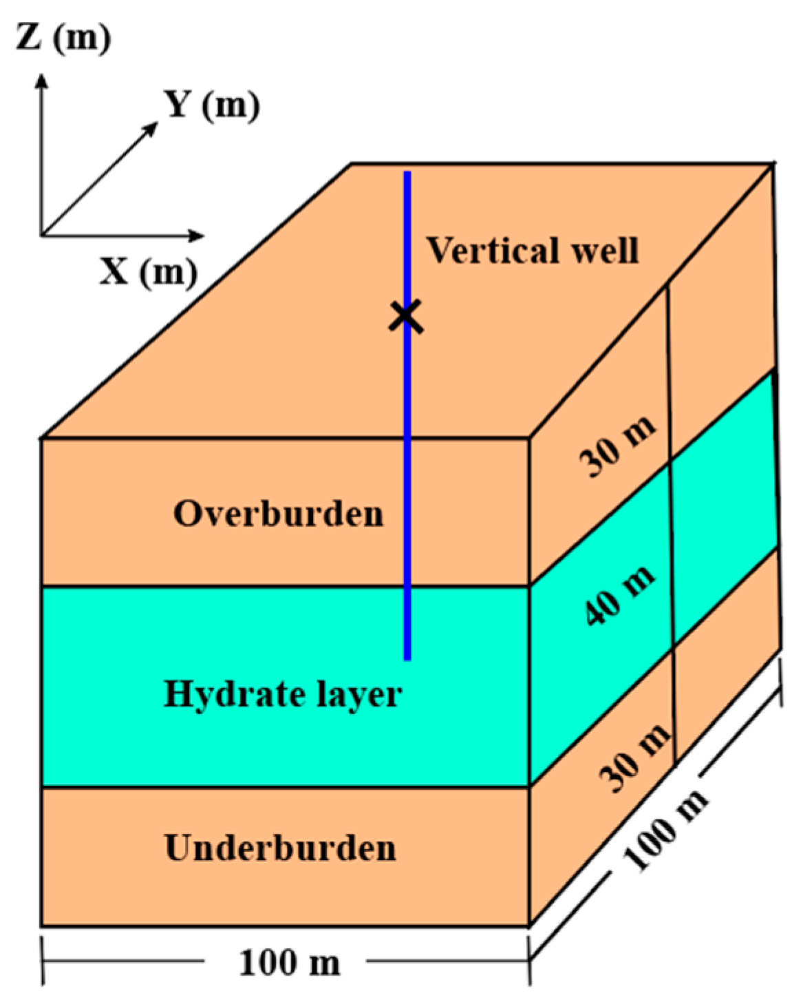
2.3. Model Geometry and Spatial Discretization

The area where site GMGS2-16 is located was selected to establish the depressurization production model for HBS. The water depth is 871 m, and the seismic profile shows that there is a seabed-like reflector (BSR) at 180–220 mbsf, which indicated that the occurrence zone of mixed pore- and fracture-filling hydrate was 180–220 mbsf. As shown in Figure 5, the simulation area is 100 m × 100 m × 100 m (X, Y, Z). Due to the small size of the fracture-filling hydrate, a higher precision mesh discretization was required to describe the fracture. Considering the limited computing capacity of Tough + Hydrate software, the mesh precision in the X direction was 0.4 m, and 250 layers were equally divided; the mesh precision of the hydrate layer in the Z direction was 0.4 m, and the mesh precision of overburden and underburden was 3.0 m. In total, 120 layers were equally divided, and 1 layer was set in the Y direction for calculation. The whole model was divided into 250 × 1 × 120 = 30,000 grids. Table 2 lists the main properties and physical parameters of HBSs at site GMGS2-16.

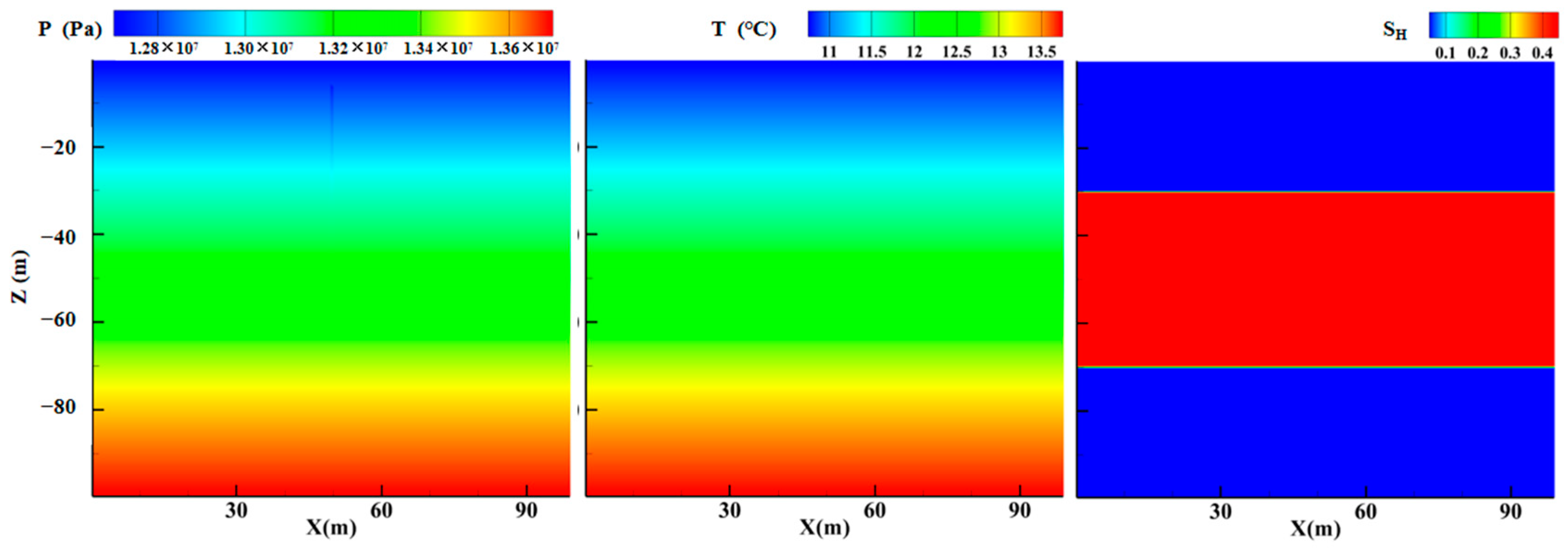
2.4. Initial and Boundary Conditions

In the model, the initial temperature gradually increased from the seafloor temperature (5.34 °C) based on the geothermal gradient (34.7 °C/km), and the initial pressure was determined by the hydrostatic pressure based on the depth and density of sedimentary water. Figure 6 depicts the spatial distribution of initial seepage parameters in the model, where the initial temperature and pressure distribution at the bottom of hydrate reservoir are 12.97 °C and 13.5 MPa, respectively [45,46].
The upper and lower boundaries of the models were permeable layers at constant pressure and temperature, enabling fluid flows and heat discharge. The lateral boundary of the models was a Dirichlet boundary (constant temperature and pressure). The production well was designed to have no fluid flow and heat exchange boundary and can be considered a constant pressure boundary with constant depressurization at 8 MPa.

2.5. Numerical Simulation Code

The Tough + Hydrate code (T + H) was developed by the Lawrence Berkeley National Laboratory of the United States based on the underground multi-phase seepage numerical simulation code TOUGH 2 coupled with the NGH formation/decomposition process calculation module and can be used to calculate the NGH production process in land permafrost areas and marine sediments.
The T + H code is a compositional simulator, and its formulation accounts for heat and four mass components (e.g., H2O, CH4, hydrate, and water-soluble inhibitors such as salts or alcohols) in four possible phases (gas, aqueous liquid, ice, and hydrate). When the T + H code is used to solve the multiphase flow during NGH production, the following assumptions are usually made: (1) the fluid flow obeys Darcy’s law; (2) the reservoir pressure is less than 100 MPa; (3) the injection of the inhibitor does not change the thermophysical properties of the fluids, and the volatile and mechanical dispersion of the inhibitor are ignored; and (4) the decrease in temperature would increase the salt concentration, but no precipitation occurs, i.e., dissolved salts do not precipitate as their concentration increases during water freezing. Consequently, the aqueous phase does not disappear when salts are present [47].

3. Results and Analysis

First, the evolution process of gas and water production and seepage parameters was analyzed in the depressurization production of HBS with pore-filling hydrate only. Then, the depressurization production behaviors of HBSs with different dipping angles fractures containing high saturation hydrate were studied, and the impacts of fracture-filling hydrates on the production behavior of the HBS was compared and analyzed. The necessity of considering mixed pore- and fracture-filling hydrates were illustrated. Finally, based on the geological information of site GMGS2-16, a fracture area was randomly generated; the fracture in this area was filled with high saturation hydrate, and optimization studies of depressurization production of HBSs with two types of mixed hydrate was conducted.

3.1. Production Behaviors of the HBS with Pore-Filling Hydrate Only

Figure 7 shows the evolution of the methane release rate (QP), the cumulative volume of methane (VP), the cumulative volume of water (VW), and the cumulative volume of methane remaining in the reservoir (VRem) of case 0 (base case).
Hydrate decomposition is a process controlled by temperature and pressure. In the early stage of production, the decomposition process was dominated by the depressurization mechanism. The pressure difference between the well-bore and reservoir was large, and the transmission of pressure-drop led to the hydrate being far away from the phase equilibrium state and decomposing it in the low-pressure area; large amounts of water and methane gas were generated. QP increased rapidly and reached a peak at approximately 300 m3/d in this stage. Then, because the hydrate decomposition was limited by heat supply and seepage capacity, the QP decreased gradually to a steady value of approximately 59 m3/d. The methane gas produced by hydrate decomposition was divided into two parts: one (VP) was released by the production well, and the other (VRem) was retained in the reservoir due to the limitation of the gas discharge capacity. As shown in Figure 7, in the early stage of hydrate rapid decomposition, due to the large amount of hydrate decomposition, the amounts of VP and VRem were similar. Later, the hydrate decomposition was limited, the gas production and discharge rate of the reservoir were similar, the VRem did not change significantly, and the VP increased steadily. By the end of the simulation, VP was approximately 77,335 m3, and VRem was approximately 25,950 m3. With the exploitation of hydrate, the water produced by hydrate decomposition and the pore water in the reservoir were also discharged, and Vw increased steadily to 52,400 m3.

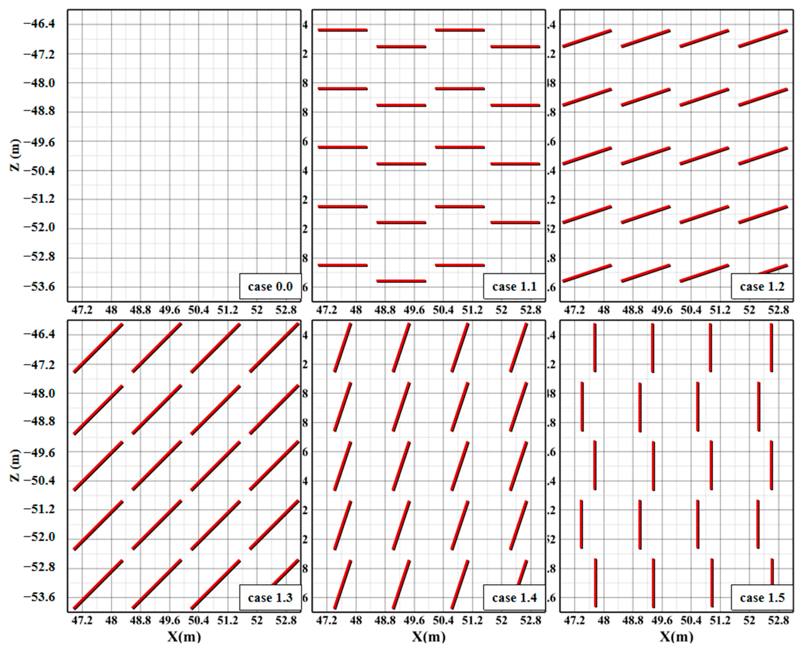
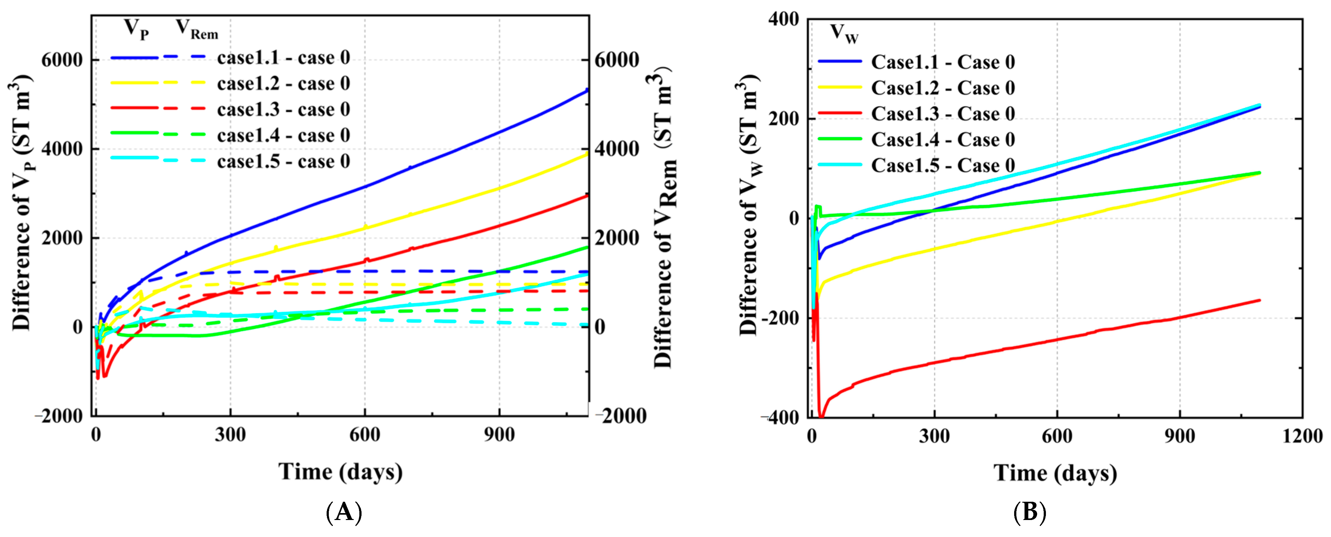
3.2. Impact of Fracture-Filling Hydrate on HBS Production

Based on the HBS with pore-filling hydrate only, the fracture-filling hydrates with different dipping angles were depicted. Fractures rarely exist alone, and most appear in groups in the fractured zone. Therefore, when depicting fracture-filling hydrates, it is necessary to first describe the fractured zone in the geological model. Then, high-saturation hydrates with different forms were filled in fractures.
The basic scheme (case 0) was HBS without fracture-filling hydrates, in order to research the impact of fracture-filling hydrate with differ dipping angles on HBS production. Five typical fractures with different dipping angles were considered in this study: 0° (case 1.1), 26° (case 1.2), 45° (case 1.3), 63° (case 1.4), and 90° (case 1.5). As shown in Figure 8, the fractured zone was located near the wellhead of the production well. There were 20 fractures with specific dipping angles distributed in the area, a single fracture was 0.4 m wide and 1.6 m long, the hydrate saturation in the fracture was 0.5 (Jin P et al., 2020), and the permeability was 1000 mD.
Figure 9 shows the difference in gas and water production between the HBS with mixed pore- and fracture-filling hydrates and that with pore-filling hydrates only. The gas production performance of the HBS containing fracture-filling hydrates was better than that of the HBS containing only pore-filling hydrate. With the increase in the fracture dipping angle, VP of cases 1.1–1.5 changed by +7.0%, +5.3%, +4.5%, +2.3%, and +1.6%, respectively, and VRem changed by +4.9%, +3.8%, +3.3%, +1.6%, and +0.3%, respectively. The sum of these two parts was the total amount of gas produced by hydrate decomposition; therefore, the occurrence of fracture-filling hydrates could promote gas productivity, and the smaller the dipping angle of the fracture, the greater the promotion degree to the gas productivity of the HBS. The water production difference was small, and VW of cases 1.1–1.5 changed by +0.5%, +0.2%, −0.2%, +0.2%, and +0.5%, respectively. Therefore, the water productivity of the HBS containing fracture-filling hydrates was similar to that of the HBS containing pore-filling hydrates only, and its gas productivity increased significantly. Thus, the gas–water ratio increased correspondingly.
Figure 10 shows the spatial distribution of temperature, pressure, and hydrate saturation in the HBS at the end of the simulation. Depressurization of the production well reduced the pore water pressure around the well and rapidly propagated the pressure-drop in the reservoir, leading to hydrate decomposition within a certain range. The heat absorption of hydrate decomposition caused the temperature in the decomposition region to decrease. As shown in Figure 10, the ranges of pressure, temperature, and hydrate saturation change were similar; they were concentrated near the producing well.
Compared with the HBS containing pore-filling hydrates only, that with mixed pore- and fracture-filling hydrates had a larger range of depressurization transfer, and the temperature drop in the fractured zone was more intense. This indicated that hydrates decompose in large quantities in the fracture zone, and because the temperature decreased too quickly and the heat recharge was not timely, the secondary hydrates could easily form in the fractured zone. Based on the spatial distribution of hydrate saturation, the fractures with a larger dipping angle were more likely to form secondary hydrate because the methane gas was more likely to vertically migrate and accumulate in the upper part of those fractures. Close to the seabed at a lower relative temperature, it was favorable for a large amount of methane gas to re-form hydrate.
In conclusion, the existence of fracture-filling hydrates has a significant impact on the evolution of gas and water production, and seepage parameters in the HBS. In addition, the smaller the dipping angle of fracture, i.e., the closer the fracture is to the horizontal, the stronger the promotion effects on the HBS production. Therefore, it is necessary to consider mixed pore- and fracture-filling hydrates in HBS.

3.3. Optimization of Depressurization Production in HBSs with Mixed Fracture- and Pore-Filling Hydrates

Previous studies have shown that the dipping angle of fractures in the HBS at site GMGS2-16 is 20–46° [38]. Therefore, random generation was used to insert 20 fractures in the fractured zone; the dipping angle of these fractures was 26°or 45°. The specific distribution of fractures is shown in Figure 11.
Section 3.2 discussed the impact of fracture-filling hydrates on HBS depressurization production, and the specific impact degree of fracture-filling hydrates with different dipping angles was different. Therefore, this section proposes the optimization study of HBSs in which the fracture-filling hydrates and pore-filling hydrates are mixed during depressurized production. Considering the low regional temperature and the formation of secondary hydrate caused by fracture-filling hydrate decomposition in the HBS, this study used the heat-injection method to assist depressurization production. Case 2.1 was only the depressurization production scheme for HBS; case 2.2 was its optimization scheme; heat injection was conducted based on depressurization; and the temperature of injected water was 60 °C.
Figure 12 shows the gas and water production before and after optimization. After optimization, the VP, VRem, and VW of HBS with mixed fracture- and pore-filling hydrates changed by +20.3%, +16.0%, and +10.2%, respectively. Therefore, hot water injection could significantly improve the gas productivity of HBS, resulting in a slight increase in water productivity. Therefore, the gas–water ratio also increased after optimization.
Figure 13 shows the spatial distribution of temperature and hydrate saturation in the HBS at the end of the simulation. The temperature and hydrate saturation range of the HBS increased after optimization, verifying the relevant analysis of gas and water production. Moreover, the problem of secondary hydrate in the fractures was solved.
In the depressurization production of HBS with mixed fracture- and pore-filling hydrates, proper heat injection could effectively improve gas productivity. In the HBS with pore-filling hydrate only, heat could only be exchanged through conduction (contact transfer between water and rock); hot water flowed through contact with rock particles to supply the heat in the low-temperature area caused by hydrate decomposition. This supply mode was similar to the piston movement of water flow. When there were fracture-filling hydrates in HBS, natural fractures would provide a transportation shortcut for water flow with high temperature, allowing the water to supply heat through thermal convection, which was similar to the short-cut movements of water flow. Therefore, the existence of fractures could greatly improve the heat transfer efficiency. The decomposition of high saturation hydrate in fractures was more likely to cause low regional temperatures and the formation of secondary hydrate. The rapid transport of high temperature water in fractures could solve these problems.
In conclusion, the proper injection of hot water played a significant role in promoting the depressurization production of HBS with mixed fracture- and pore-filling hydrates, and it is necessary to optimize the depressurization production process.

4. Conclusions

In this study, the effects of fracture-filling hydrates with different dipping angles on the hydrate production process were studied, and the necessity of considering mixed pore- and fracture-filling hydrates mixed in HBS was illustrated. On this basis, the simulation model of a typical site (GMGS2-16) with mixed pore- and fracture-filling hydrates was constructed, the production research was conducted, and the production method was optimized. The following conclusions were drawn:
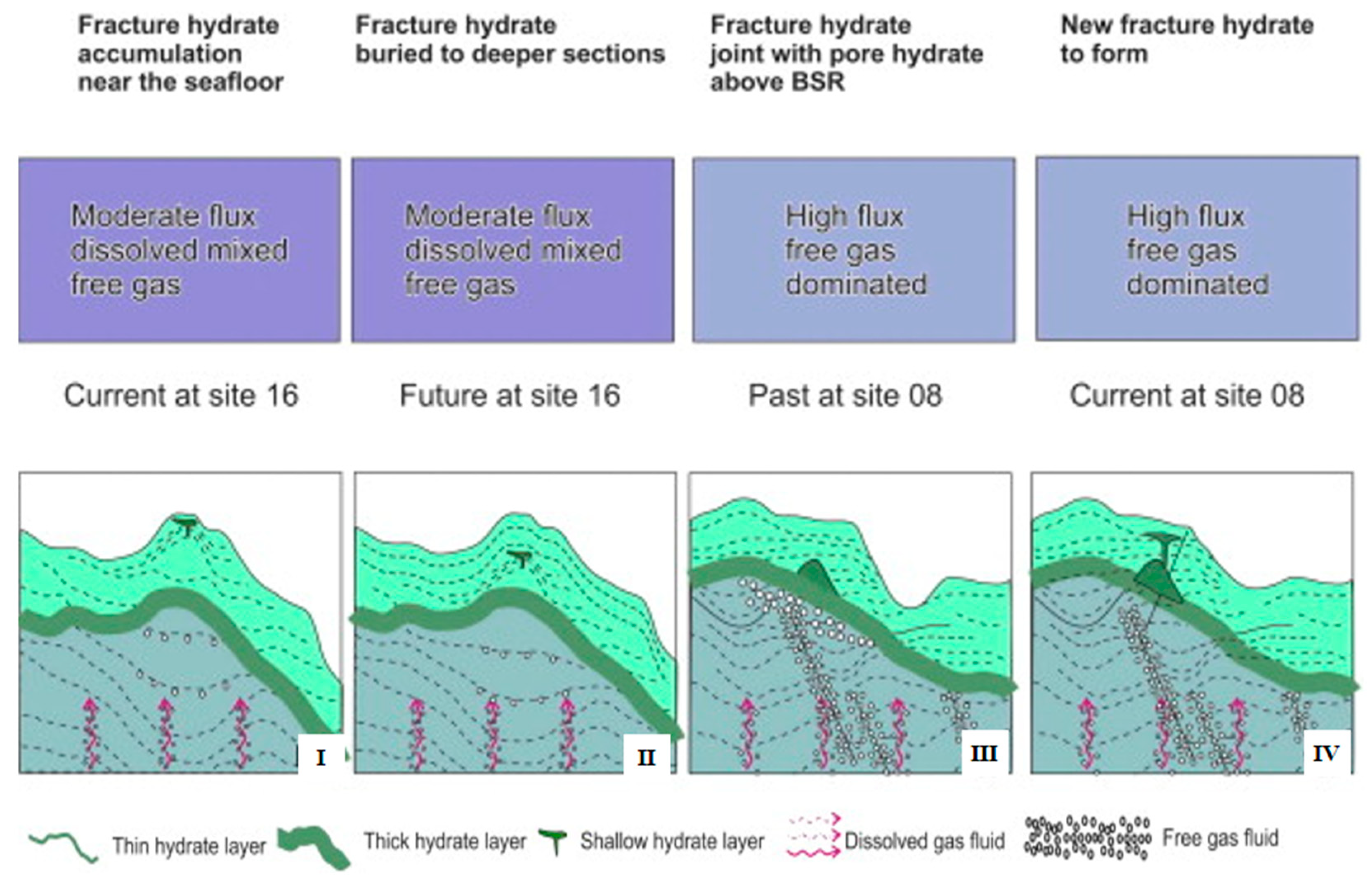
  • Due to the combined influence of temperature and pressure, gas source, the migration of gas-bearing fluid, and reservoir conditions, the fracture-filling hydrates formed in shallow fine-grained sediments and gradually migrated towards the pore-filling hydrate occurrence area. Finally, a stable occurrence area formed, containing both fracture- and pore-filling hydrates.
  • The occurrence of fracture-filling hydrates could promote HBS production, compared with that containing pore-filling hydrates only. With the increase in the fracture dipping angle (cases 1.1–1.5), the gas productivity changed by +6.5%, +4.9%, +4.2%, +2.1%, and +1.3%, respectively. Therefore, the smaller the dipping angle of the fracture, the greater the promotion degree to the HBS production.
  • During depressurization of the HBS with mixed pore- and fracture-filling hydrates, the problem of the low regional temperature and the formation of secondary hydrate caused by fracture-filling hydrate decomposition was significant, and the proper injection of hot water could solve these problems, promoting the depressurization production of HBS. Using the numerical simulation in this study, the gas productivity increased by 20.3% after using the heat-injection method to assist depressurization production.

Author Contributions

Conceptualization, X.X. and T.X.; methodology, Y.L. and H.Z.; software, T.X. and X.X.; validation, Z.Y.; formal analysis, Y.L. and H.Z.; investigation, Y.Z.; resources, X.X.; data curation, Y.Z. and Z.Y.; writing—original draft preparation, Y.L.; writing—review and editing, X.X., T.X. and Y.Y.; visualization, Y.Z. and Y.Y.; supervision, T.X.; project administration, X.X.; funding acquisition, X.X. All authors have read and agreed to the published version of the manuscript.

Funding

This work was supported by the National Natural Science Foundation of China (No. 42276224, and No. 42206230), the Jilin Scientific and Technological Development Program (No. 20190303083SF), the International Cooperation Key Laboratory of Underground Energy Development and Geological Restoration (No. YDZJ202102CXJD014), the Interdisciplinary Integration and Innovation Project of JLU (JLUXKJC2021ZZ18), and the Graduate Innovation Fund of Jilin University (No. 2023CX100).

Institutional Review Board Statement

Not applicable.

Informed Consent Statement

Not applicable.

Data Availability Statement

Not applicable.

Acknowledgments

We thank the support from above fundings, and thank Yuwei Chen of School of Foreign Language Education, Jilin University for great efforts to the paper grammar.

Conflicts of Interest

The authors declare no conflict of interest.

References

  1. He, J.; Zhong, C.; Yao, Y.; Yan, P.; Wang, Y.; Wan, Z.; Guan, J.; Zhang, J. Progress and prospect of gas hydrate exploration and exploration in the northern South China Sea. Mar. Geol. Front. 2020, 36, 1–14. [Google Scholar] [CrossRef]
  2. Ning, F.; Liang, J.; Wu, N.; Zhu, Y.; Wu, S.; Liu, C.; Wei, C.; Wang, D.; Zhang, Z.; Xu, M.; et al. Reservoir characters of natural gas hydrates in China. Nat. Gas Ind. 2020, 40, 1–24. [Google Scholar] [CrossRef]
  3. Zhao, J.; Liu, Y.; Guo, X.; Wei, R.; Yu, T.; Xu, L.; Sun, L.; Yang, L. Gas production behavior from hydrate-bearing fine natural sediments through optimized step-wise depressurization. Appl. Energy 2020, 260, 114275. [Google Scholar] [CrossRef]
  4. Fan, D.; Li, F.; Wang, Z.; Miao, Q.; Bai, Y.; Liu, Q. Development status and prospects of China’s energy minerals under the target of carbon peak and carbon neutrality. China Min. Mag. 2021, 30, 1–8. [Google Scholar]
  5. Cheng, F.; Wu, Z.; Sun, X.; Shen, S.; Wu, P.; Liu, W.; Chen, B.; Liu, X.; Li, Y. Compression-induced dynamic change in effective permeability of hydrate-bearing sediments during hydrate dissociation by depressurization. Energy 2023, 264, 126137. [Google Scholar] [CrossRef]
  6. Li, J.; Ye, J.; Qin, X.; Qiu, H.; Wu, N.; Lu, H.; Xie, W.; Lu, J.; Peng, F.; Xu, Z.; et al. The first offshore natural gas hydrate production test in the South China Sea. China Geol. 2018, 1, 5–16. [Google Scholar] [CrossRef]
  7. Wang, H.; Wu, P.; Li, Y.; Liu, W.; Pan, X.; Li, Q.; He, Y.; Song, Y. Gas permeability variation during methane hydrate dissociation by depressurization in marine sediments. Energy 2022, 263, 125749. [Google Scholar] [CrossRef]
  8. Zhou, S.; Li, Q.; Lv, X.; Pang, W.; Fu, Q. Thinking and suggestions on research direction of natural gas hydrate development. China Offshore Oil Gas 2019, 31, 1–8. [Google Scholar] [CrossRef]
  9. Lu, J.; Lin, D.; Li, D.; Liang, D.; Zhang, Y.; Wu, S.; He, Y.; Shi, L. Research status on water controllina and sand controllina in horizontal well completion durina gas hydrate exploitation. Adv. New Renew. Energy 2022, 10, 447–455. [Google Scholar]
  10. Wu, P.; Li, Y.; Wang, L.; Sun, X.; Wu, D.; He, Y.; Li, Q.; Song, Y. Hydrate-bearing sediment of the South China Sea: Microstructure and mechanical characteristics. Eng. Geol. 2022, 307, 106782. [Google Scholar] [CrossRef]
  11. Zhang, G.; Liang, J.; Lu, J.; Yang, S.; Zhang, M.; Su, X.; Xu, H.; Fu, S.; Kuang, Z. Characteristics of natural gas hydrate reservoir on the northeastern slope of the South China Sea. Nat. Gas Ind. 2014, 34, 1–10. [Google Scholar] [CrossRef]
  12. Uddin, M.; Wright, F.; Dallimore, S.; Coombe, D. Gas hydrate dissociation in Mallik hydrate bearing zone A, B, and C by depressurization: Effect of salinity and hydration number in hydrate dissociation. J. Nat. Gas Sci. Eng. 2014, 21, 40–63. [Google Scholar] [CrossRef]
  13. Zhu, H. Numerical Study on Sand Production Processes during Natural Gas Hydrate Recovery and Its Impact on Gas Production. Ph.D. Thesis, Jilin University, Changchun, China, 2021. [Google Scholar]
  14. Yang, C.; Liu, J.; Yang, R.; Hu, X.; Yao, Y.; Wang, Z.; Li, X. Occurrence and resource potential of gas hydrate in the Alaska north slope basin of the Arctic. Chin. J. Polar Res. 2019, 31, 309–321. [Google Scholar] [CrossRef]
  15. Sha, Z.; Xu, Z.; Wang, P.; Liang, J.; Wan, X.; Wan, L.; Su, P. World progress in gas hydrate research and its enlightenment to accelerating industrialization in China. Mar. Geol. Front. 2019, 35, 1–10. [Google Scholar] [CrossRef]
  16. Li, Y.; Xin, X.; Xu, T.; Zhu, H.; Wang, H.; Chen, Q.; Yang, B. Comparative analysis on the evolution of seepage parameters in methane hydrate production under depressurization of clayey silt reservoir and sandy reservoir. J. Mar. Sci. Eng. 2022, 10, 653. [Google Scholar] [CrossRef]
  17. Zhu, Y.; Zhang, Y.; Fang, H.; Lu, Z.; Pang, S.; Zhang, S.; Xiao, R. Main progress of investigation and test production of natural gas hydrate in permafrost of China. Geol. Surv. China 2020, 7, 1–9. [Google Scholar] [CrossRef]
  18. Kuang, D.; He, B.; Wang, D. Logging evaluation of gas hydrate at leg 204 of ODP in hydrate ridge. Sci. Technol. Inf. 2013, 17, 1–2. [Google Scholar] [CrossRef]
  19. Zhao, E.; Hou, J.; Du, Q.; Liu, Y.; Ji, Y.; Bai, Y. Numerical modeling of gas production from methane hydrate deposits using low-frequency electrical heating assisted depressurization method. Fuel 2021, 290, 120075. [Google Scholar] [CrossRef]
  20. Wang, J.; Wu, S.; Yao, Y.; Li, B. Advances in geophysical research on gas hydrate reservoirs on the east continental margin of India. J. Trop. Oceanogr. 2017, 6, 90–99. [Google Scholar] [CrossRef]
  21. Huang, W.; Zhang, W.; Liang, J.; Shang, J.; Meng, M.; Shan, C. Comparative study of gas hydrate accumulation system in the Qiongdongnan Basin of the South China Sea and the Ulleung Basin of Korea. J. China Univ. Min. Technol. 2021, 50, 363–380. [Google Scholar]
  22. Bei, K.; Xu, T.; Shang, S.; Wei, Z.; Yuan, Y.; Tian, H. Numerical modeling of gas migration and hydrate formation in heterogeneous marine sediments. J. Mar. Sci. Eng. 2019, 7, 348. [Google Scholar] [CrossRef] [Green Version]
  23. Zhao, K.; Sun, C.; Guo, J.; Wu, C. Enrichment characteristics and accumulation mechanism of natural gas hydrate in the Gulf of Mexico: Cases study of study area WR313 and GC955. Reserv. Eval. Dev. 2021, 11, 669–679. [Google Scholar] [CrossRef]
  24. Yu, T.; Guan, G.; Abudula, A.; Yoshida, A.; Wang, D.; Song, Y. Application of horizontal wells to the oceanic methane hydrate production in the Nankai Trough, Japan. J. Nat. Gas Sci. Eng. 2019, 62, 113–131. [Google Scholar] [CrossRef]
  25. Yin, Z.; Wan, Q.; Gao, Q.; Linga, P. Effect of pressure drawdown rate on the fluid production behavior from methane hydrate-bearing sediments. Appl. Energy 2020, 271, 115195. [Google Scholar] [CrossRef]
  26. Rita, G.; Alberto, G.; Andrea, R.; Beatrice, C.; Marco, M.; Marco, Z.; Andrea, N.; Federico, R. Thermodynamic assessment and microscale Raman spectroscopy of binary CO2/CH4 hydrates produced during replacement applications in natural reservoirs. J. Mol. Liq. 2022, 368, 120739. [Google Scholar] [CrossRef]
  27. Alberto, G.; Li, Y.; Federico, R. Influence of different proportion of CO2/N2 binary gas mixture on methane recovery through replacement processes in natural gas hydrates. Chem. Eng. Process. 2022, 175, 108932. [Google Scholar] [CrossRef]
  28. Wang, X.; Sain, K.; Satyavani, K.; Wang, J.; Ojha, M.; Wu, S. Gas hydrates saturation using geostatistical inversion in a fractured reservoir in the Krishna-Godavari basin, offshore eastern India. Mar. Pet. Geol. 2013, 45, 224–235. [Google Scholar] [CrossRef]
  29. Cai, J.; Xia, Y.; Xu, S.; Tian, H. Advances in multiphase seepage characteristics of natural gas hydrate sediments. Chin. J. Theor. Appl. Mech. 2020, 52, 208–223. [Google Scholar] [CrossRef]
  30. Zhu, H.; Xu, T.; Yuan, Y.; Xia, Y.; Xin, X. Numerical investigation of natural gas hydrate production tests in the Nankai Trough by incorporating sand migration. Appl. Energy 2020, 275, 115384. [Google Scholar] [CrossRef]
  31. Ghosh, R.; Ojha, M. Amount of gas hydrate estimated from rock physics analysis based on morphology and intrinsic anisotropy in area B, Krishna Godavari offshore basin, expedition NGHP-02. Mar. Pet. Geol. 2021, 124, 104856. [Google Scholar] [CrossRef]
  32. Yuan, Y. Numerical Simulation on Gas Production Potential and the Geomechanical Stability from Marine Natural Gas Hydrate through Depressurization. Ph.D. Thesis, Jilin University, Changchun, China, 2019. [Google Scholar]
  33. Xia, Y. Multi-scale joint study on dynamic evolution characteristics of reservoir seepage parameters during hydrate dissociation. Ph.D. Thesis, Jilin University, Changchun, China, 2022. [Google Scholar]
  34. Zhang, B.; Yu, Y.; Jin, K.; Wu, Q.; Gao, X.; Wu, Q.; Liu, C. Influence of depressurization amplitude and saturation in loose sediments on the dissociation process of natural gas hydrates. Nat. Gas Ind. 2020, 40, 133–140. [Google Scholar] [CrossRef]
  35. Peng, D.; Chen, C.; Pang, X.; Zhu, M.; Yang, F. Discovery of deep-water fan system in South China Sea. Acta Pet. Sin. 2004, 25, 17–23. [Google Scholar]
  36. Liang, J.; Zhang, G.; Lu, J.; Su, P.; Sha, Z.; Gong, Y.; Su, X. Accumulation characteristics and genetic models of natural gas hydrate reservoirs in the NE slope of the South China Sea. Nat. Gas Ind. 2016, 36, 157–162. [Google Scholar] [CrossRef]
  37. He, J.; Zhu, Y.; Wen, R.; Cui, S. Characters of north-west mud diapirs volcanoes in South China Sea and relationship between them and accumulation and migration of oil and gas. Earth Sci. 2010, 35, 75–86. [Google Scholar] [CrossRef]
  38. Zhao, J.; Wang, J.; Cen, Y.; Su, P.; Lin, Q.; Liu, J. Authigenic minerals at site GMGS2-16 of northeastern South China Sea and its implications for gas hydrate evolution. Mar. Geol. Quat. Geol. 2018, 38, 144–155. [Google Scholar] [CrossRef]
  39. Zhao, J.; Wang, J.; Stephen, C.; Liang, J.; Su, P.; Lin, Q.; Chen, C.; Liu, J. Non-evaporitic gypsum formed in marine sediments due to sulfate-methane transition zone fluctuations and mass transport deposits in the northern South China Sea. Mar. Chem. 2021, 233, 103988. [Google Scholar] [CrossRef]
  40. Sha, Z.; Liang, J.; Zhang, G.; Yang, S.; Lu, J.; Zhang, Z.; McConnell, D.; Humphrey, G. A seepage gas hydrate system in northern South China Sea: Seismic and well log interpretations. Mar. Geol. 2015, 366, 69–78. [Google Scholar] [CrossRef]
  41. Kuang, Z.; Fang, Y.; Liang, J.; Lu, J.; Wang, L. Geomorphological-geological-geophysical signatures of high-flux fluid flows in the Eastern Pearl River Mouth Basin and effects on gas hydrate accumulation. Sci. China Earth Sci. 2018, 48, 1033–1044. [Google Scholar] [CrossRef]
  42. Liu, T. Identification of marine gas hydrate morphology. Ph.D. Thesis, China University of Geosciences, Beijing, China, 2019. [Google Scholar]
  43. Jin, P.; Hu, G.; Bu, Q.; Chen, J.; Wan, Y.; Mao, X. Identification of pore-filling and fracture-filling hydrate by petrophysical simulation and acoustic experiment. Mar. Geol. Quat. Geol. 2020, 40, 208–218. [Google Scholar] [CrossRef]
  44. Xin, X.; Wang, H.; Luo, J.; Yu, H.; Yuan, Y.; Xia, Y.; Zhu, H.; Chen, Q. Simulation-optimization coupling model for the depressurization production of marine natural gas hydrate in horizontal wells based on machine learning method. Nat. Gas Ind. 2020, 40, 149–158. [Google Scholar] [CrossRef]
  45. Li, Y.; Xu, T.; Xin, X.; Wang, H.; Zhu, H. Study on gas hydrate reservoir reconstruction for enhanced gas production in Shenhu area of the South China Sea based on 3D heterogeneous geological model. Energy Fuels 2022, 36, 12695–12707. [Google Scholar] [CrossRef]
  46. Li, Y.; Xin, X.; Xu, T.; Zang, Y.; Yuan, Y.; Zhu, H.; Shan, Y. Study of Multibranch Wells for Productivity Increase in Hydrate Reservoirs Based on a 3D Heterogeneous Geological Model: A Case in the Shenhu Area, South China Sea. SPE J. 2023; SPE-215814-PA, in press. [Google Scholar] [CrossRef]
  47. Moridis, G.; Reagan, T.; Boyle, L.; Zhang, K. Evaluation of the gas production potential of some particularly challenging types of oceanic hydrate deposits. Transp. Porous Media 2011, 90, 269–299. [Google Scholar] [CrossRef]
Figure 1. Speciation diagrams of hydrate samples in GMGS2. (a,b) Blocky hydrate; (ce) layered hydrate; (f) nodular hydrate; (g) vein-like hydrate; (h) dispersed hydrate (from Ning et al. [3]).
Jmse 11 01321 g001
Figure 2. Location of the research area in the Shenhu area of the South China Sea. The GMGS1, GMGS3, and GMGS4 drilling campaigns were completed in the Shenhu area; the GMGS2 drilling campaign was completed in the Taixinan Basin; the GMGS5 drilling campaign was completed in the Qiongdongnan Basin (from Zhao et al. [38]. Copyright (2021) Publisher Elsevier).
Jmse 11 01321 g002
Figure 3. Profile containing eight sites of the GMGS2 drilling campaign. Blue indicates zones of hydrate occurrence or well log anomalies. GHS refers to the gas hydrate saturation. The spatial relationship of the sites is depicted in the lower left corner (from Sha et al. [39]. Copyright (2015) Publisher Elsevier).
Jmse 11 01321 g003
Figure 4. Geological interpretation of hydrate formation in the study area. The fracture-filling hydrates were found to be formed in shallow fine-grained sediments, gradually migrating to the pore-filling hydrate occurrence area (I–IV) (from Sha et al. [39] Copyright (2015) Publisher Elsevier).
Jmse 11 01321 g004
Figure 5. Conceptual model of hydrate-bearing sediment. The simulation area is 100 m × 100 m × 100 m (X, Y, Z). The vertical well was used for natural gas hydrate production.
Jmse 11 01321 g005
Figure 6. Initial spatial distribution of seepage parameters (pressure, P; temperature, T; and hydrate saturation, SH) in the hydrate-bearing sediment.
Jmse 11 01321 g006
Figure 7. Evaluation of QP, VP, VW, and VRem during gas production from the hydrate-bearing sediments with pore-filling hydrate only. The huge pressure drop made a large amount of hydrate decompose and discharge quickly in the early stage of depressurization, then, because the hydrate decomposition was limited by heat supply and seepage capacity, there is a stable gas and water production process.
Jmse 11 01321 g007
Figure 8. Distribution of fractures with different dipping angles in the fractured zone. The dipping angle of fractures in cases 1.1, 1.2, 1.3, 1.4, and 1.5 are 0°, 26°, 45°, 63°, and 90°, respectively.
Jmse 11 01321 g008
Figure 9. Differences in VP, VRem, and VW between the hydrate-bearing sediments considering fracture-filling hydrate and those with pore-filling hydrate only. The gas production performance of the HBS containing fracture-filling hydrates was better than that of the HBS containing only pore-filling hydrate, and the water productivity of the HBS containing fracture-filling hydrates was similar to that of the HBS containing pore-filling hydrates only. (A) VP and VRem; (B) VW.
Jmse 11 01321 g009
Figure 10. Differences in VP, VRem, and VW between the hydrate-bearing sediments considering the fracture-filling hydrate and those with pore-filling hydrate only. Compared with the HBS containing pore-filling hydrates only, that with mixed pore- and fracture-filling hydrates had a larger range of depressurization transfer, and the temperature drop in the fractured zone was more intense.
Jmse 11 01321 g010aJmse 11 01321 g010b
Figure 11. Fracture distribution at site GMGS2-16. Twenty fractures in the fractured zone were inserted by random generation, and the dipping angles of these fractures were 26° or 45°.
Jmse 11 01321 g011
Figure 12. Evaluation of VP, VRem, and VW for basic and optimization schemes. After optimization, the gas productivity was obviously improved.
Jmse 11 01321 g012
Figure 13. Spatial distribution of seepage parameters for basic and optimization schemes. The temperature and hydrate saturation range of the HBS increased after optimization.
Jmse 11 01321 g013
Table 1. Natural gas hydrate characteristics of global gas hydrate reservoirs [13,32,33].
TypeCountryAreaSediment TypeType of Natural Gas Hydrate
Land
areas
CanadaMallikSandy mainlyPore-filling hydrate mainly
USAAlaska North SlopeSandyPore-filling hydrate mainly
ChinaMuli BasinSiltstone and Clayey siltFractured-filling hydrate mainly, followed by fractured-filling and pore-filling mixed
Marine
areas
USABlake RidgeClayey silt mainlyPore-filling hydrate: dispersed and nodular hydrate
Hydrate RidgeFine sandy mainlyFractured-filling hydrate mainly
Gulf of MexicoFine sandy mainlyFractured-filling hydrate with partial pore-filling hydrate
JapanNankai TroughSandyPore-filling hydrate mainly
IndiaK-G BasinSandy and ClayeyPore-filling and fractured-filling hydrate
ChinaShenhu areaClayey siltDispersed, nodular, blocky, and thin-layered hydrate
Pearl River Mouth BasinClayey siltPore-filling: dispersed hydrate
Qiongdongnan BasinClayey siltNodular, blocky, vein-like, layered, and dispersed hydrate
KoreaUlleung BasinSandyPore-filling and fractured-filling hydrate
Table 2. Main properties and model parameters of the hydrate-bearing sediments at GMGS2-16 [40,41,42,43,44].
ParameterValueParameterValue
Thickness of HBS (m)40Thickness of overburden/underburden (m)30
Porosity of HBS0.53Porosity of overburden/underburden0.58
Hydrate saturation of pore-filling hydrate0.42Hydrate saturation of fracture-filling hydrate0.50 [42]
Permeability of HBS (mD)10Permeability of overburden/underburden5
Initial temperature at the base of HBS (°C)12.97Geothermal gradient (°C/100 m)3.47
Initial pressure at the base of HBS (MPa)13.5Dry thermal conductivity (W/m/K)1.0
Rock grain density (kg/m3)2600Wet thermal conductivity (W/m/K)3.1
Specific heat capacity of hydrate (kJ/kg/K)2.1Water salinity3.05%
Disclaimer/Publisher’s Note: The statements, opinions and data contained in all publications are solely those of the individual author(s) and contributor(s) and not of MDPI and/or the editor(s). MDPI and/or the editor(s) disclaim responsibility for any injury to people or property resulting from any ideas, methods, instructions or products referred to in the content.

