1. Introduction
To control a ship, one must consider the complex interactions between the ship’s motion and external factors such as currents, waves, and wind. These factors can cause the ship to deviate from its desired course, and the hydrodynamic forces acting on the hull and rudder further complicate the challenge of maintaining stability. Developing an effective autopilot system is therefore critical. In pursuit of this goal, a mathematical model of the ship in six degrees of freedom [
1] was constructed and simulated using MATLAB [
2]. The model was analyzed while taking into account the nonlinear factors that affect the ship’s behavior under the influence of external forces. To simplify the design process, some of the nonlinear factors were sometimes neglected. Additionally, the relationship between the steering gear and propeller was analyzed, as it directly affects the ship’s speed and direction. To provide the controller with an accurate representation of the ship’s operation and enable the testing of new control methods, the mathematical model was further refined to isolate the components that exclusively affect the course of the ship, such as the rudder, propeller, and hydrodynamic forces [
3]. Test experiments were conducted on actual ships, and simulation techniques were utilized to determine the parameters of the model. Finally, the general principles of the navigation controller and the system of floating means on the sea were discussed in an overview.
The global maritime industry is an essential contributor to economic development, with a rich history as one of the earliest developed industries. Ships continue to evolve, becoming increasingly modern and capable of carrying larger loads to meet the growing demands of freight transport, tourism, and national defense. In light of advanced technology, there has been a heightened focus on developing automatic control systems for ships [
4]. These complex systems are designed to replace human control and accomplish advanced tasks.
In the maritime industry, autopilot systems play a crucial role in ship control by allowing for precise direction control in the ship’s previous direction of travel [
5]. The implementation of a well-designed autopilot system can significantly reduce crew workload and fuel consumption and shorten voyage times.
The benefits of automatic control [
6], mentioned above, along with the significant advancements in wireless data transmission, have led to more sophisticated control requirements. Specifically, automatic mode control and remote monitoring capabilities enable operators to directly control ships from a distance or establish remote parameters for automatic control mode. These requirements are particularly necessary for ships that need to navigate complex and challenging marine terrain that is difficult for humans to access or in dangerous areas. Additionally, they are essential for the future of seafaring. Underwater vehicles, for instance, do not require human presence.
The maritime industry has made significant progress in ship autopilot technology since the installation of the first autopilot on the J.A. Moffet in 1920. Early autopilot systems used PID controllers in combination with other methods. Although the PID algorithm is simple and easy to apply, it has limitations as the optimal PID coefficients only work well under certain conditions, which are constantly changing during transport and affected by environmental factors. Hence, the use of PID controllers [
7] in automatic ship steering systems is limited.
Until the 1980s, the application of computers and microcontrollers led to the development of new theories and various types of controllers, including fuzzy logic application controllers [
8], neural networks [
9], and expert systems. These controllers have gradually solved the limitations of PID controllers mentioned above. They are still a topic of interest to researchers due to their versatility and high flexibility. Therefore, it is crucial to research and apply modern control techniques [
10] to the automatic ship steering system to adapt to changing working conditions. In response to this practical demand, the authors propose a study titled “Design and Control of an Autopilot System for Ships using an Intelligent Controller based on Adaptive Neuro Fuzzy Inference System”.
The use of Adaptive Neuro-Fuzzy Inference System (ANFIS) controllers [
11,
12,
13] has been increasing in various fields, including control engineering, signal processing, and industrial automation. ANFIS controllers are widely used in applications such as robotics, aerospace systems, automotive control, and process control. In recent years, ANFIS controllers have gained attention in the field of marine engineering, particularly in ship autopilot control. ANFIS controllers are advantageous due to their ability to handle nonlinear and complex systems, which are prevalent in marine engineering. Some studies have shown that ANFIS controllers can improve the performance of ship autopilot control, such as reducing fuel consumption and improving the accuracy of the ship’s course. However, further research and development are still needed to optimize the ANFIS controller’s performance and ensure its reliability and robustness in real-world applications. Overall, the use of ANFIS controllers is a promising direction in the field of marine engineering and ship autopilot control. The basic structure of the study:
Part 1: Brief introduction to ROV and ANFIS.
Part 2: Building dynamics, controller, signal noise.
Part 3: Simulation results and discussion of the results.
Part 4: Making a conclusion.
The study results were simulated on MATLAB/Simulink, providing a more precise comparison and evaluation of the controller’s performance. This simulation also demonstrated the controller’s effectiveness when compared to a conventional PID controller.
After simulation, the following are some of the innovations of the ANFIS controller in ship control:
High flexibility: The ANFIS controller has the ability to adapt and learn from the conditions and parameters of the ship, making it work well in different conditions such as weather, waves, loads, speed, etc.
Ability to adjust accuracy: The ANFIS can adjust the accuracy of the control model based on the actual data collected, helping to optimize the control performance.
High availability: The ANFIS is a practical model and can be deployed on embedded computing devices such as microcontrollers, which reduces costs and increases the availability of ship control systems.
Reduce design load: The ANFIS controller can perform many functions, thereby reducing the load on the design and installation of ship control systems.
The author of this article presents the following:
Optimization of the ANFIS Model: Optimizing the ANFIS model can improve the control performance of the ship. Optimization algorithms such as genetic algorithms, particle swarm optimization, or simulated annealing can be used to adjust the parameters of the ANFIS model.
Multitasking of the ANFIS: The multitasking of the ANFIS can optimize the performance of the controller in different situations. By creating subtasks, such as speed control, direction control, and engine control, the compatibility and overall performance of the ANFIS controller can be simultaneously enhanced.
2. Materials and Methods
2.1. Autopilot System
The basic autopilot control system (
Figure 1) [
14] includes a digital compass system to position the ship’s direction, the sensor for the angular position of the rudder, a central controller to receive values from sensors and output the main motor control signal, a rudder angle motor, a control panel to select automatic control values, manual control, or control cease or start mode, and an interface screen to display the values as well as system parameters [
15].
Compass: used to determine the direction of the ship relative to the physical axis of the Earth. This compass can be used to determine the course when the ship is operating in manual mode and to determine the direction of the ship when in automatic control mode. There are two basic types of compasses: digital compass and analog compass. The digital compass has a small cross-section, is easy to disassemble and connect, and is flexible during transportation, especially for digital communication, so it can easily communicate with digital control devices and control devices with current controllers. Analog compasses have a relatively large design, difficult to move but with high accuracy.
Steering wheel angle sensor: used to determine the current rotation of the rudder because of the actuators and mechanics. There will be a deviation between the control signal of the rudder angle and the actual value of the rudder angle. The angle sensor will help control the steering wheel better and match the desired value of the steering angle. The steering angle sensor can be an analog sensor or a digital sensor and using a positioning encoder will make the signal response more accurate and faster.
The Adaptive Neuro-Fuzzy Inference System (ANFIS) is regarded as a comprehensive and well-suited controller for the automatic control of maintaining a ship’s pre-set course. It is highly effective due to its precise learning capabilities and remarkable stability, achieved through rapid feedback responses aimed at minimizing errors.
2.2. Dynamic Model of the Ship
The proposed research advocates for the implementation of a 6DOF controller for ships due to its numerous advantages. Firstly, a 6DOF controller enhances maneuverability by granting control over six fundamental ship motions, enabling more effective navigation and adaptability to diverse operational circumstances. Secondly, the additional degrees of freedom provided by a 6DOF controller contribute to improved stability control, crucial for maintaining equilibrium and ensuring safety during complex maneuvers and challenging sea conditions. Thirdly, precise positioning of the ship, both horizontally and vertically, is facilitated by the capability to govern all six degrees of freedom, essential for critical activities such as docking, berthing, and navigating narrow channels. Moreover, a 6DOF controller equips ships with the necessary control capabilities to promptly respond to environmental variations, ensuring stability and responsiveness in dynamic marine environments. In summary, the implementation of a 6DOF controller surpasses the advantages of a 3DOF controller, empowering ships with enhanced control precision, stability, effective navigation, and adaptability to changing sea conditions. Thus, the authors chose 6DOF for simulation in this paper.
In order to describe the motion of a ship [
16], a six-degrees-of-freedom kinematic model is commonly employed. Depending on the required accuracy and specifications, the number of degrees of freedom can be adjusted, but the current trend is to use a 3-degrees-of-freedom model with an absolute coordinate system and a system of relative coordinates. The ship’s position (x,y) and orientation (ψ) in the X
EY
EZ
E absolute coordinate system (the coordinate system associated with the Earth) are represented as the vector η = [x,y,ψ]
T. The velocity along the vertical and horizontal axes, as well as the rotational velocity about the vertical axis, are represented by the vector ν = [u,v,r]
T. The center of the XYZ relative coordinate system (the coordinate system attached to the ship) is located in the axial plane of the ship, at a distance of x
G from the center of gravity.
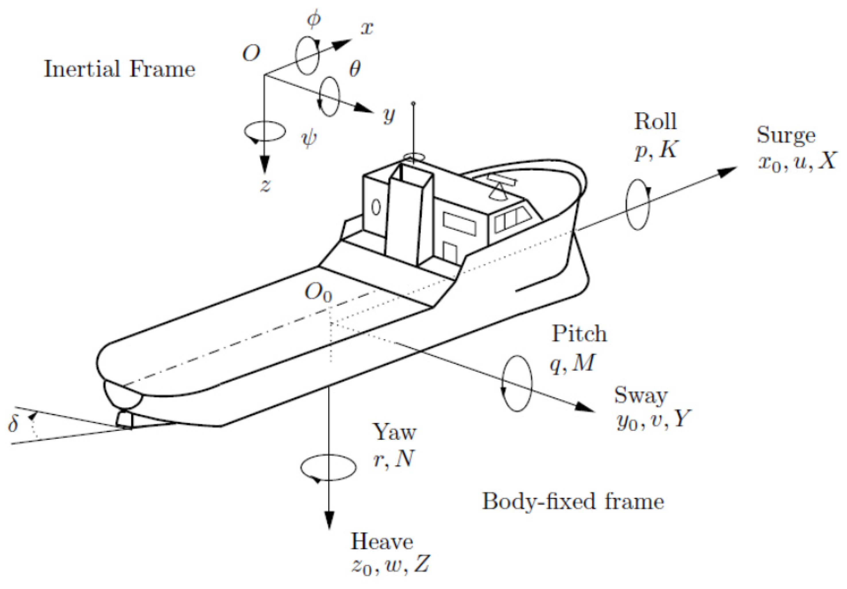
Figure 2 illustrates the ship’s coordinate system [
16,
17]. The motion components and kinematic parameters of the ship are presented in
Table 1.
In which: Oxyz—Earth coordinate system: NED (North East Down) or Inertial Frame.
Obxbybzb—Coordinate system associated with the ship position in which the center of gravity of the ship coincides with the origin: BODY or body—Fixed Frame.
In this paper, to enhance the accuracy and reliability of the autopilot system, the authors propose a simulation using a 6-degrees-of-freedom model for ships. Ships are complex vehicles that operate in a challenging environment and are influenced by various unpredictable factors such as wind, waves, and currents. The dynamics of ship motion are governed by Newton’s laws, which consider the ship as a solid object moving in a fluid medium and describe the motion of the ship using six degrees of freedom (DOF) [
17,
18,
19]. The six degrees of freedom (DOFs), depicted in
Figure 2, encompass heave, sway, surge, roll, pitch, and yaw. The objective of this study is to examine the influence of these factors on ship motion and present a solution to enhance the stability and performance of the ship under different operational circumstances. The ship’s balancing motion at any position is shown in (1) [
16,
17,
18,
19].
where:
—the thrust vector, which in this paper is supplied by the engines and steering systems of the vessel.
η—the position vector, used to orient with the Earth reference frame (n-frame) and is defined by the following components:
v—the velocity vector, the angular velocity vector in the body-fixed coordinate system, is determined by:
The relationship between
v and
η is described by:
In which
J(
η)—the transformation matrix, which depends on Euler angles (
φ,
θ,
ψ) and has the form [
18].
where:
where
s(.) = sin(.),
c(.) = cos(.) and
t(.) = tan(.)
Matrix of inertia—
M, determined by the formula:
where
MRB—the inertia matrix generated by the ship itself (treating the hydrodynamics of the ship as the mechanics of a rigid body), calculated by Formula (6) [
18].
where:
m—the mass of the ship.
Ixx, Izz—the moment of inertia about the x0 and z0 axes.
—the center of gravity coordinates of the ship.
U, v—the velocity and lateral displacement of the ship.
MA—the added mass matrix, created by the forces and moments due to the fluid (water) inertia. Around the fluid, there is always movement, and this impact force is proportional to the velocity of the ship. The value of
MA is determined according to (7) [
20].
The Coriolis matrix—
C(
v), is determined by the following formula:
where
—the centripetal Coriolis matrix, characteristic of the hydrodynamics of solids, and determined according to (9) [
14].
CA(
v)—the Coriolis matrix generated by the added mass due to the forces and moments of fluid inertia, determined according to (10) [
18].
Inertia-induced vibration matrix—
D(
v): The hydrodynamic forces of sway motion caused by the inertia of the liquid, mainly dependent on the friction between the water and the hull, water drift, and vortex, determined according to (11) [
21,
22].
Force and moment of gravity vector—
g(
η): This force is generated by the gravity and buoyancy of the ship under the action of water on the hull. The force of gravity and buoyancy will act on the ship’s center of gravity and is determined according to (12) [
18].
With:
W = mg submerged weight of the body;
B = buoyancy force;
is the water density;
is the volume of fluid displaced by the ship;
g = 9.81 m/s2: gravitational acceleration;
: center of gravity coordinates of the ship;
: center of buoyancy coordinates of the ship.
Force vector and moment of the control signal: Described by the matrix—
τ and determined by the following formula [
19].
consists of the following components:
where:
τhyd—force and moment generated by the motion between the ship’s body and the water.
τcs—force and moment created by the action of the rudder and auxiliary rudder (fin).
τprop—force and moment created by the action of the main propulsion force.
τext—force and moment created by the impact of environmental disturbances: waves, wind, currents, etc.
The forces and moments generated by the rudder: The force due to the rudder action is calculated according to (13) [
19,
23].
δ—rudder angle: To ensure the forces and moments generated by the rudder, the angle of the rudder deflection is limited in magnitude by −δmax ≤ δ ≤ δmax, where δmax = 35° and the rate of deflection.
The moment generated by the rudder action is calculated according to (14).
where:
are the coordinates of the vessel’s center of gravity.
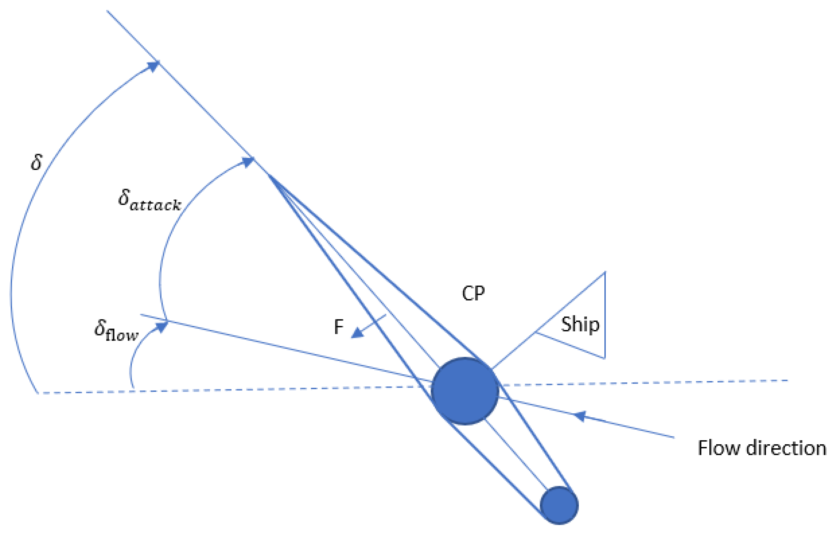
are the coordinates of the center of pressure of the rudder forces in a fixed coordinate system (
Figure 3), calculated according to Equation (14).
CF—lift coefficient;
Ar—area of the rudder;
Vav—average velocity of the flow acting on the rudder;
δattack—angle of attack between the rudder and the flow;
δstall—the rudder stall angle.
2.3. ANFIS Controller
When using the ANFIS controller in the ship motion model, the differences from the traditional control model will be:
- -
More accurate train control;
- -
Error minimization;
- -
Flexible ship control;
- -
Optimized system performance.
With the ability to learn and self-correct, the ANFIS controller can make decisions based on fuzzy rules and input parameters, helping to optimize system performance and minimize errors in the control process. This makes ship control more precise and more responsive to control requirements.
In addition, the ANFIS controller also helps to control the train flexibly and respond well to different situations thanks to its ability to adapt to changing conditions during train operation. From there, it helps to optimize the ship’s performance and reduce the time it takes to complete the missions.
In this study, the proposed neural–fuzzy controller is a neural–fuzzy system based on Takagi and Sugeno’s Approach. It is also an Adaptive Neuro-Fuzzy Inference System (ANFIS) [
24,
25,
26,
27,
28,
29,
30,
31,
32,
33]. The proposed controller has two inputs,
and
, and one output:
.
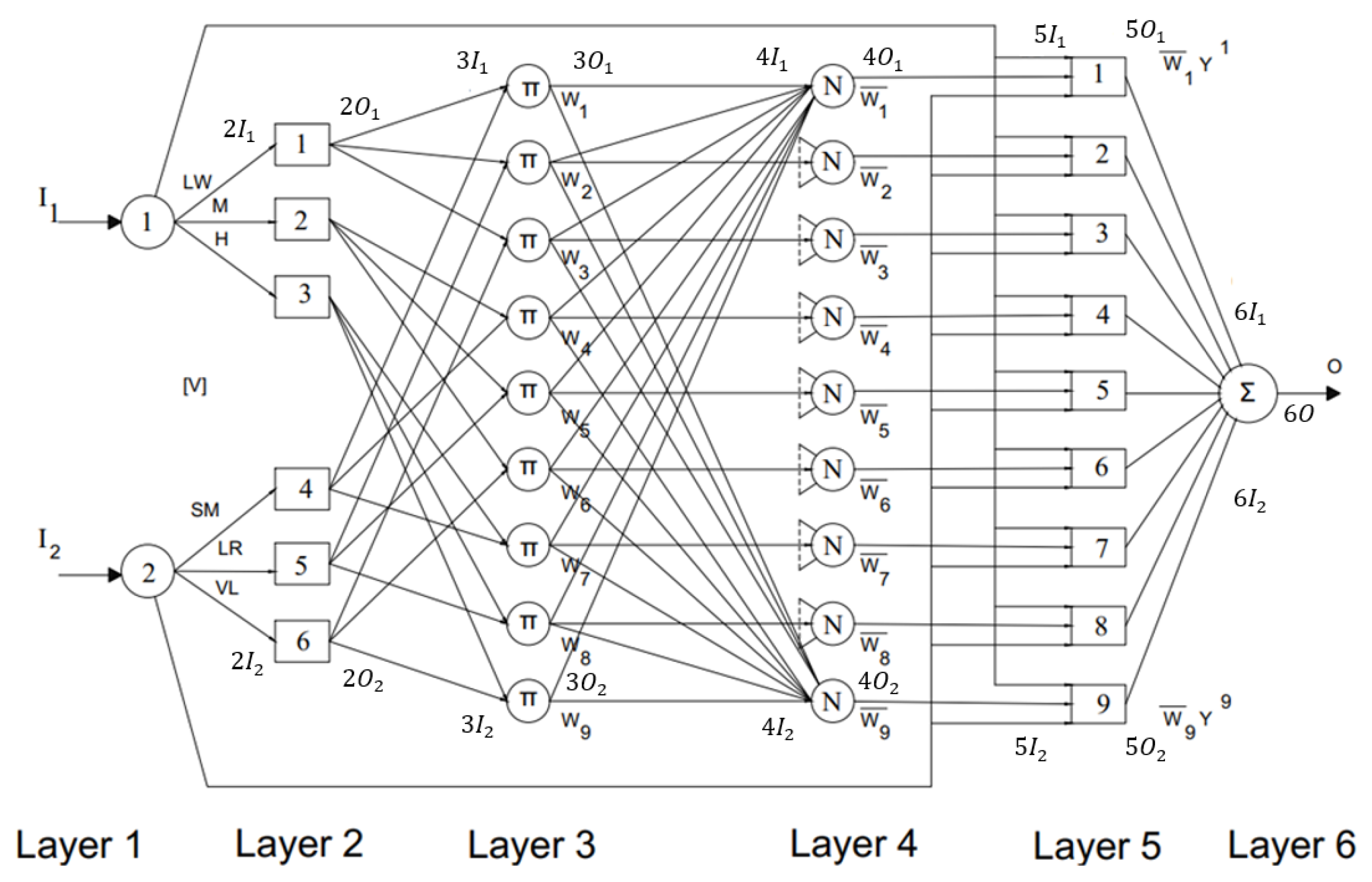
The main difference of the composition rule (
Figure 4) is that the conclusion of the rule takes the form of a linear equation of the input variables. The ANFIS controller consists of 6 layers. Layer 1 consists of 2 input signals, and layer 2 consists of 6 nodes representing the 6 rules of the fuzzy system. Layers 3, 4, and 5 all have 9 nodes, and, finally, layer 6 consists of 1 node that synthesizes the output signals from layer 5.
According to the first-order Takagi–Sugeno model of fuzzy logic control:
where:
i = 1, 2, …, 9.
are coefficients.
The distribution of the membership function of the input and output variables is shown in
Figure 5.
If is LW and is LW, then O will be S: ;
If is M and is LW, then O will be S: ;
If is H and is LW, then O will be F: ;
If is LW and is M, then O will be S: ;
If is M and is M, then O will be F: ;
If is H and is M, then O will be VF: ;
If is LW and is H, then O will be F: ;
If is M and is H, then O will be VF: ;
If is H and is H, then O will be VF: ;
where:
- -
(The output in the controller is the rudder angle of the ship and the main input is the error of the set value and the error speed;) w—the weight of the connections between neurons in the neural network (
Figure 6).
LW: Low;
M: Medium;
H: High;
S: Slow;
F: Fast;
VF: Very fast.
The structure of the ANFIS controller consists of 6 layers.
Layer 1:
Linear TF (output = input)
Layer 2:
Fuzzification (µ)
Layer 3:
The firing strengths of the rules are calculated considering the products of µ values:
Layer 4:
Calculate the normalized firing strength of each rule:
where:
n = 1, 2, …. 9.
Layer 5:
The output is calculated as the product of normalized firing strength and output of the corresponding fired rule
y
where:
n = 1, 2, …, 9.
Layer 6:
The error loss function
E is given by:
where:
is the actual output value.
is the desired output value.
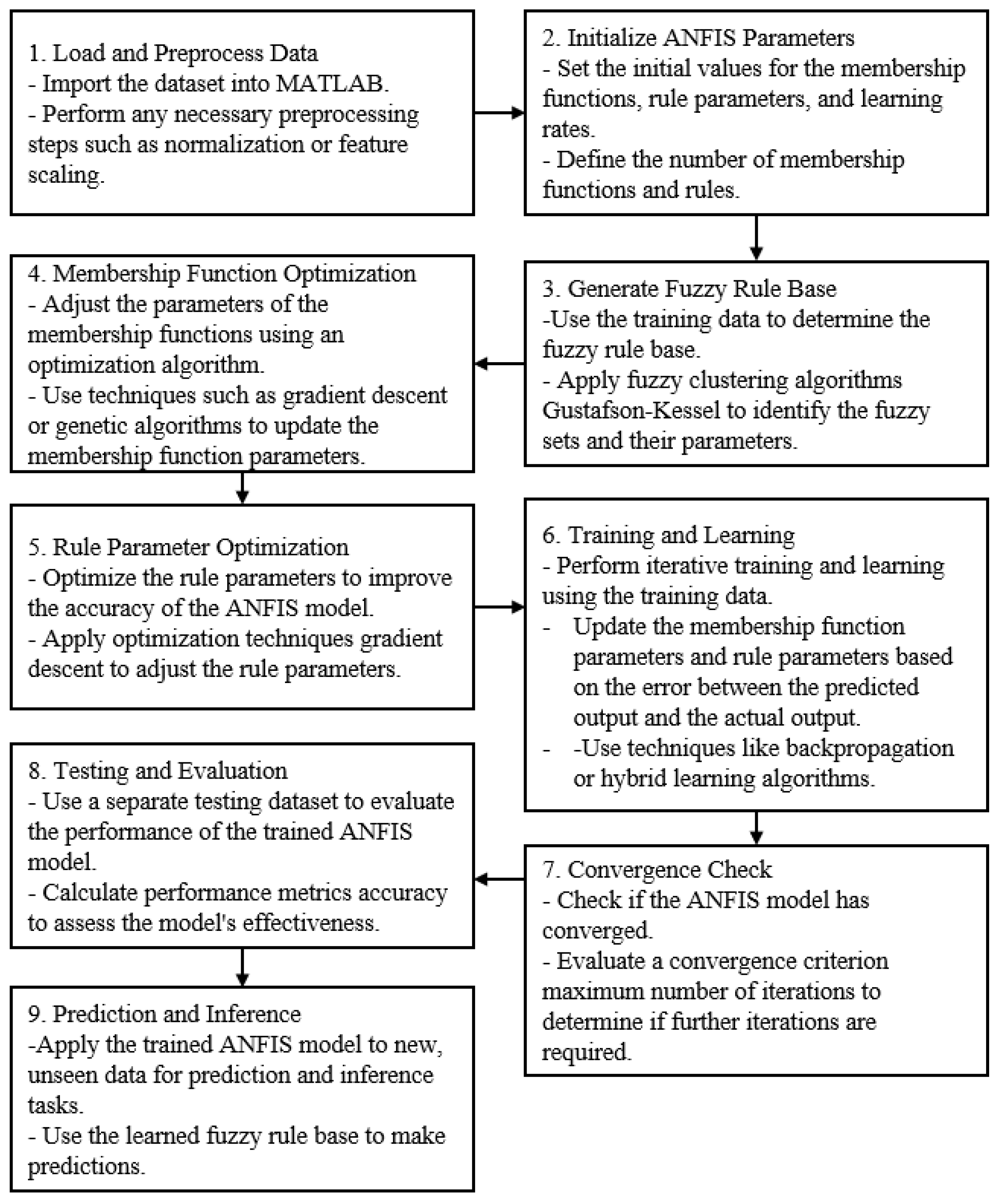
In step 5, use the gradient descent algorithm:
Gradient descent is an iterative optimization algorithm used for finding the minimum of a function. The formula for updating the parameters in each iteration is as follows:
where:
: updated parameter values.
: current parameter values.
α (alpha): learning rate, which determines the step size in each iteration.
: gradient of the cost function J with respect to the parameters .
Building an ANFIS Controller using MATLAB (Algorithm 1):
| Algorithm 1: ANFIS setting algorithm |
% Create the initial FIS model from the training data
fis = genfis2(Inputmatrix, Outputmatrix, ANFIS_Controller_Ship.fis);
numObs = 5;
% Configure the ANFIS model
anfisConfig = anfisOptions(‘InitialFIS’, fis, ‘EpochNumber’, 100, ‘DisplayANFISInformation’, 0);
% Train the ANFIS model
[anfisOutput, trainError] = anfis([trainInput, trainOutput], anfisConfig);
% Predict the output for the testing set
testOutput = evalfis(testInput, anfisOutput);
% Evaluate the performance of the model
mse = immse(testOutput, testOutputExpected);
rsquared = 1 − mse/var(testOutputExpected);
observationInfo = rlNumericSpec([numObs 1]);
observationInfo.Name = ‘observations’;
numAct = 1;
actionInfo = rlNumericSpec([numAct 1]);
actionInfo.LowerLimit = −1;
actionInfo.UpperLimit = 1;
actionInfo.Name = ‘Control’;
actionInfo.Description = ‘Thurst’;
mdl = ‘ANFIS_ Controller_Ship’;
load_system(mdl);
blk = [mdl,’/RL Data’]; |
2.4. Disturbance
The high-frequency wave pattern is described as follows. When subjected to high-frequency interference, it primarily affects the ship model through first-order interference. The equation approximately demonstrates the linearity of the high-frequency interference spectrum [
34]:
With the coefficient Kw being dependent on the sea state Kw = 2zwsw, where sw is the coefficient describing the wave density, z is the relative damping factor, and w is the drift frequency (design parameter). The relative damping factor z can be chosen at random and z < 10.
The linear state space model when converted to the time variable of the transfer function
h(
s) is as follows:
The ship’s high-frequency wave pattern in terms of forward, drift, and return motion can be described as the following differential equations [
35]:
where
wx,
wy,
wΨ are Gaussian white noise processes. The relative damping factor and the chosen wave frequency are equal in the forward, reverse, and drift motions [
36]. This is a good approximation in real life. The high-frequency wave model is written as an equation of state as follows:
The low-frequency flow model is calculated as follows. It is assumed that the flow is constant in both direction and amplitude, such that the flow rate
Vc and direction
βc can be modeled as slowly varying parameters in the Earth axis system. The flow rate according to the hull axis system is obtained through the conversion of the shaft system.
Assume ΨL and ΨH are the rotational components of the low-frequency and high-frequency effects, respectively, in addition to uc, vc, and the rotational flow component rc.
The low-frequency wind model is presented as follows. The low-frequency wind speed
Vw and direction
βw are modeled as slowly varying quantities. It can represent this model as a state space, as follows:
where
Xwind,
Ywind, and
Nwind are given by the following formulae:
where
Cx,
Cy, and
CN are the coefficients of drag and torque,
AT and
AL are the transverse and side projection areas,
L is the length of the ship, and
VR and
gR are the wind speed and direction acting on the ship and are calculated as follows:
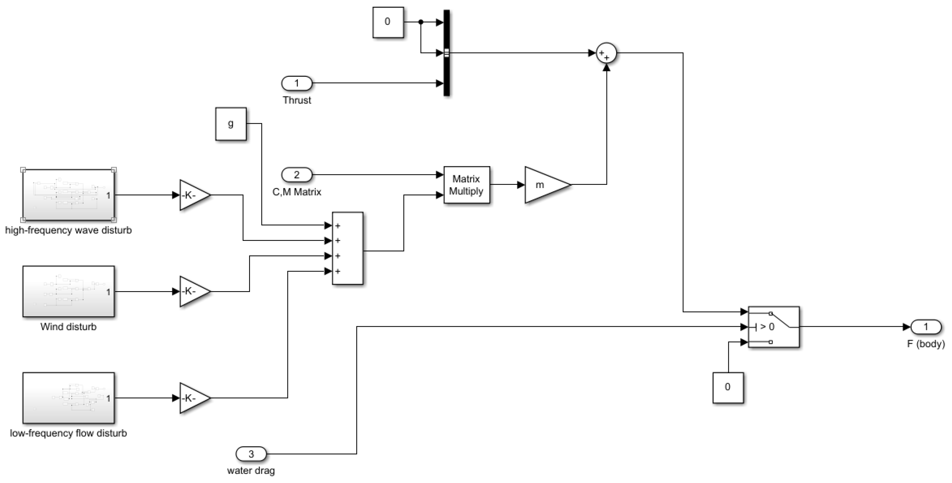
The noise simulated in MATLAB/Simulink is shown in
Figure 7:
2.5. Stability of a Ship
- -
Static Stability Point:
The static stability point of a ship refers to the condition where the ship is in a stable equilibrium and resists tilting or capsizing. It is determined by the metacentric height (GM) of the ship, which measures the distance between the center of gravity (G) and the metacenter (M) when the ship is inclined.
The formula to calculate the metacentric height (
GM) is:
where:
GMt is the metacentric height, which represents the distance between the metacenter and the keel base.
KB is the distance between the keel base and the center of gravity of the ship.
A positive GM indicates that the metacenter is above the center of gravity, providing stability to the ship. A higher GM value implies greater stability against tilting. On the other hand, a negative GM indicates an unstable condition, as the metacenter is below the center of gravity.
- -
Dynamic Stability:
The dynamic stability of a ship refers to its ability to resist rolling motions and maintain a stable condition while in motion, particularly in response to external forces such as waves or wind. It is determined by factors such as the ship’s moment of inertia (I) and weight (W).
The period of roll is a key parameter used to assess the dynamic stability of a ship. It represents the time taken for the ship to complete one full cycle of rolling motion and return to its initial upright position. The formula to calculate the period of roll is:
where:
I is the moment of inertia of the ship, which quantifies its resistance to rotational motion. It depends on the mass distribution and shape of the ship.
W is the weight of the ship, which is the force acting vertically downward due to the ship’s mass.
A shorter period of roll indicates that the ship is more responsive to external forces and experiences faster rolling motions. On the other hand, a longer period of roll implies slower and more stable rolling motions, indicating better dynamic stability.
- -
Righting Lever Curve:
The righting lever curve is typically plotted as a graph with the angle of heel on the x-axis and the righting lever or righting arm on the y-axis. The righting lever represents the horizontal distance between the center of gravity (G) and the center of buoyancy (B) of the ship at a specific angle of heel. It indicates the moment created by the buoyant force acting on the ship’s hull to counteract the heeling moment caused by external forces.
The shape of the righting lever curve provides important information about the ship’s stability. Key points on the curve include:
Initial Stability: At small angles of heel, the righting lever curve shows a positive slope, indicating that the ship has a righting moment that increases as the angle of heel increases. This initial positive slope signifies the ship’s initial stability.
Maximum Righting Lever: The point on the curve where the righting lever is at its maximum represents the maximum righting moment that the ship can generate. This point corresponds to the angle of heel at which the ship reaches its maximum stability.
Angle of Vanishing Stability: Beyond a certain angle of heel, the righting lever curve starts to decline, indicating a decrease in the righting moment. The angle at which the righting lever becomes zero or negative is known as the angle of vanishing stability or the angle of capsizing. It represents the point at which the ship becomes highly unstable and prone to capsizing.
- -
Static Trim Moment:
The static trim moment of a ship refers to the moment created by a change in the ship’s draft or trim, resulting from a shift in weight or cargo distribution. It measures the force acting on the ship to bring it back to its desired trim condition.
The formula to calculate the static trim moment is:
where:
W represents the weight of the ship or the total mass of the vessel, including cargo, fuel, ballast, equipment, and other components.
∆KG is the change in the vertical distance between the center of gravity (G) and the keel (K) of the ship due to a change in draft or trim.
The static trim moment reflects the tendency of the ship to return to a balanced trim condition when it is disturbed. If the static trim moment is positive, it means that the ship will experience a moment that tends to restore its trim to its original condition. Conversely, a negative static trim moment indicates that the ship will tend to maintain or further deviate from its existing trim.
- -
Neutral Buoyancy Condition:
The neutral buoyancy condition of a ship refers to the state where the ship is in equilibrium, with the forces of buoyancy and weight balanced, resulting in no vertical acceleration or inclination. In this condition, the ship neither sinks nor rises in the water.
To achieve the neutral buoyancy condition, two primary factors need to be considered:
Center of Gravity (CG): The center of gravity is the point at which the entire weight of the ship can be considered to act vertically downward. It is determined by the distribution of the ship’s weight, including cargo, fuel, ballast, equipment, and other components.
Center of Buoyancy (CB): The center of buoyancy is the point at which the buoyant force acts vertically upward on the ship. It depends on the shape and volume of the underwater portion of the ship’s hull and is typically located at the geometric center of the underwater volume.
In the neutral buoyancy condition, the center of gravity and the center of buoyancy are aligned vertically, and their vertical forces balance each other out. This alignment ensures that there is no heeling moment or vertical acceleration acting on the ship.
2.6. Simulation in MATLAB/Simulink
A ship steering system applying ANFIS has the basic structure shown in the block diagram (
Figure 8) below.
Trajectory Generator Block: the system generates cruise data with the input of weather data and information about the position and direction of the ship from the navigation system (Navigation System). The trip data of this block are input to the Main Control System. The controller unit will use data from the Trajectory Generator Block and the Navigation System Block such as current position, direction, and cruise data to generate commands for the steering unit and the propulsion system. The ANFIS block is responsible for reducing errors, making the control signal more accurate, and responding faster. Ship Block: The ship’s propulsion system and the ship’s steering system. Environmental Condition: The signal of the environment affecting the ship. Block Navigation System: The navigation system of the ship. The output in the ANFIS controller is the rudder angle of the ship, and the main input is the error of the set value and the error speed.
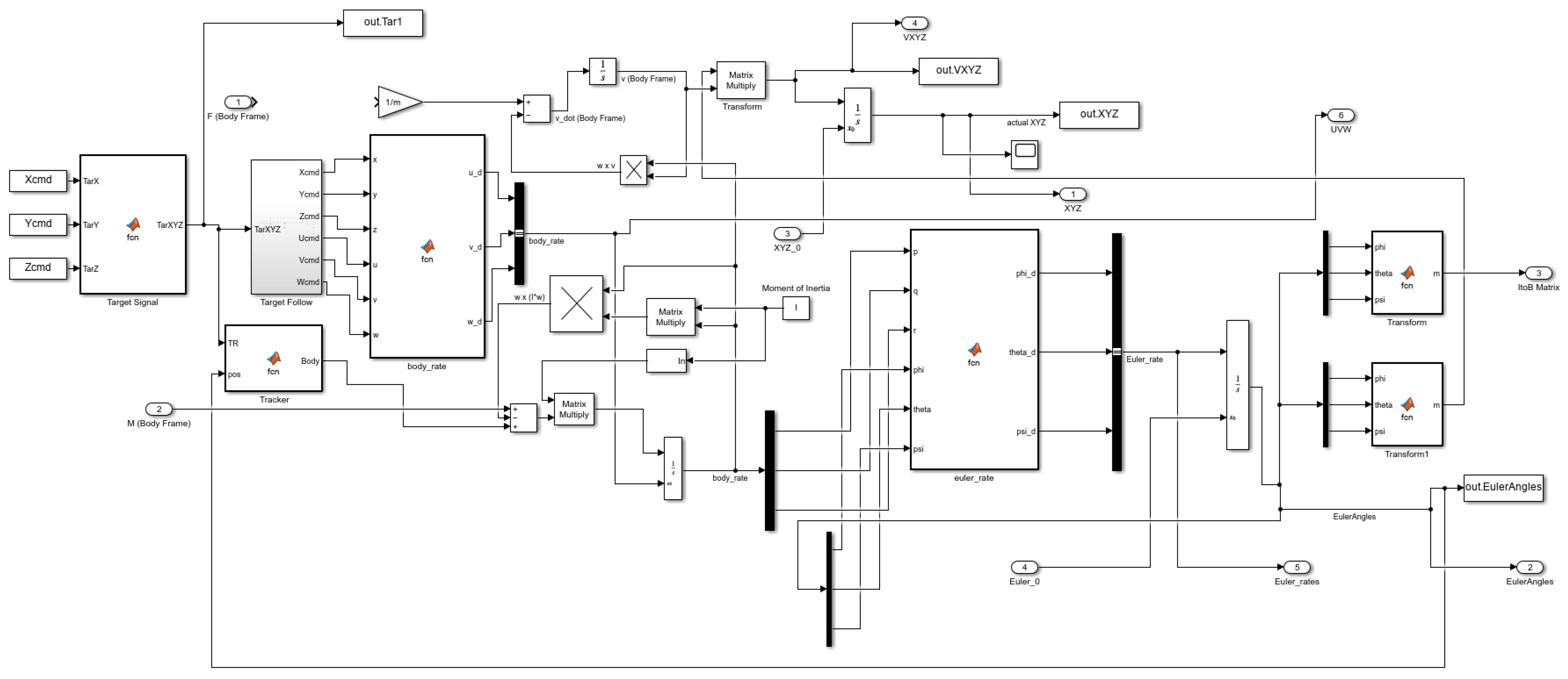
Figure 9 simulates the controller and ship dynamic 6DOF using MATLAB/Simulink based on the block diagram of the basic structure of the system.
The simulation in MATLAB/Simulink [
41] includes the ship dynamics simulation, environmental impacts, the ship steering system, and the ANFIS [
42,
43,
44] controller. In this simulation, we simulated the process of converting from a set signal and then converted by body rate and Euler rate with the ANFIS controller to the navigation angle of the ship. The controller is responsible for adjusting the ship’s direction to be closest to the set trajectory. The feedback signals in
Figure 8 and
Figure 9 indicate the feedback regarding the position coordinates of the ship. They reveal information about the deviation of the ship’s bow and the incorrect heading, prompting the controller to adjust the input signals in order to bring the ship back on track with the intended trajectory.
Working principle: first, set the initial values of angle and position, then the signal is sent to the controller as a set signal (controller input signal) through the variable controller. Convert the set signals into control signals such as rotation angle, position, and angular velocity, and then send the signal to the ANFIS. In the ANFIS unit, signals are learned and improved based on the trained learning data set required by the operator, then the signals are sent to the ship’s impact along with environmental influences. From here, signals are sent to the steering gear of the coordinate system used to steer and correct the course of the ship. Finally, the feedback signal is sent back to the controller to transform and learn at the ANFIS controller to have a controller that works correctly and suppresses noise.
3. Results and Discussion
The experiment was tested many times with real ships and model ship data [
45]. The obtained results were found to be similar, and the simulation in the article chose a simulation model. The simulation data were taken at an approximately 1:2 scale of model ship RIB 760 of QuingDao HaoHai Boat Co., Ltd., Qingdao, Shandong, China.
Table 2 shows the parameters of the test ship model. It simplified the data in the simulation in the form of a model to match the experiment of the controlled evaluation study. In reality, there may be more complex data and more influencing factors.
In this study, the manual method was employed to select the PID coefficients. The following steps were taken:
Determine the control objective: The control objective in this research is to control the direction of movement.
Determine the Kp coefficient: Starting with the proportional coefficient, Kp, set an initial value of Kp to 0 and gradually increase it until the system achieves a stable response. If the system responds slowly or is unstable, increase Kp. If the system exhibits excessive oscillations or an overly aggressive response, decrease Kp. The authors found the optimal proportional coefficient to be 1.43.
Determine the Ki coefficient: After determining Kp, determine the integral coefficient, Ki. Begin with an initial value of Ki set to 0 and gradually increase it until the system achieves a stable response and minimizes the error between the output value and the desired value. In this article, a very small value of 0.00001 was chosen for the integral coefficient.
Determine the Kd coefficient: Finally, determine the derivative coefficient, Kd. Start with an initial value of Kd set to 0 and gradually increase it until the system achieves a stable response and minimizes oscillations or waveform distortions in the response. The desired response required a Kd coefficient of 0.25.
Testing and adjustment: After determining the Kp, Ki, and Kd coefficients, test the system to ensure that it meets the control requirements. Make adjustments to the coefficient values and retest until the best performance is achieved for the ship.
Therefore, the parameters of the PID controller sought to meet the purpose of ship control are P = 1.43, I = 0.00001, and D = 0.25.
The simulation was performed with two controllers, PID and ANFIS, to compare the results [
46,
47,
48,
49,
50,
51].
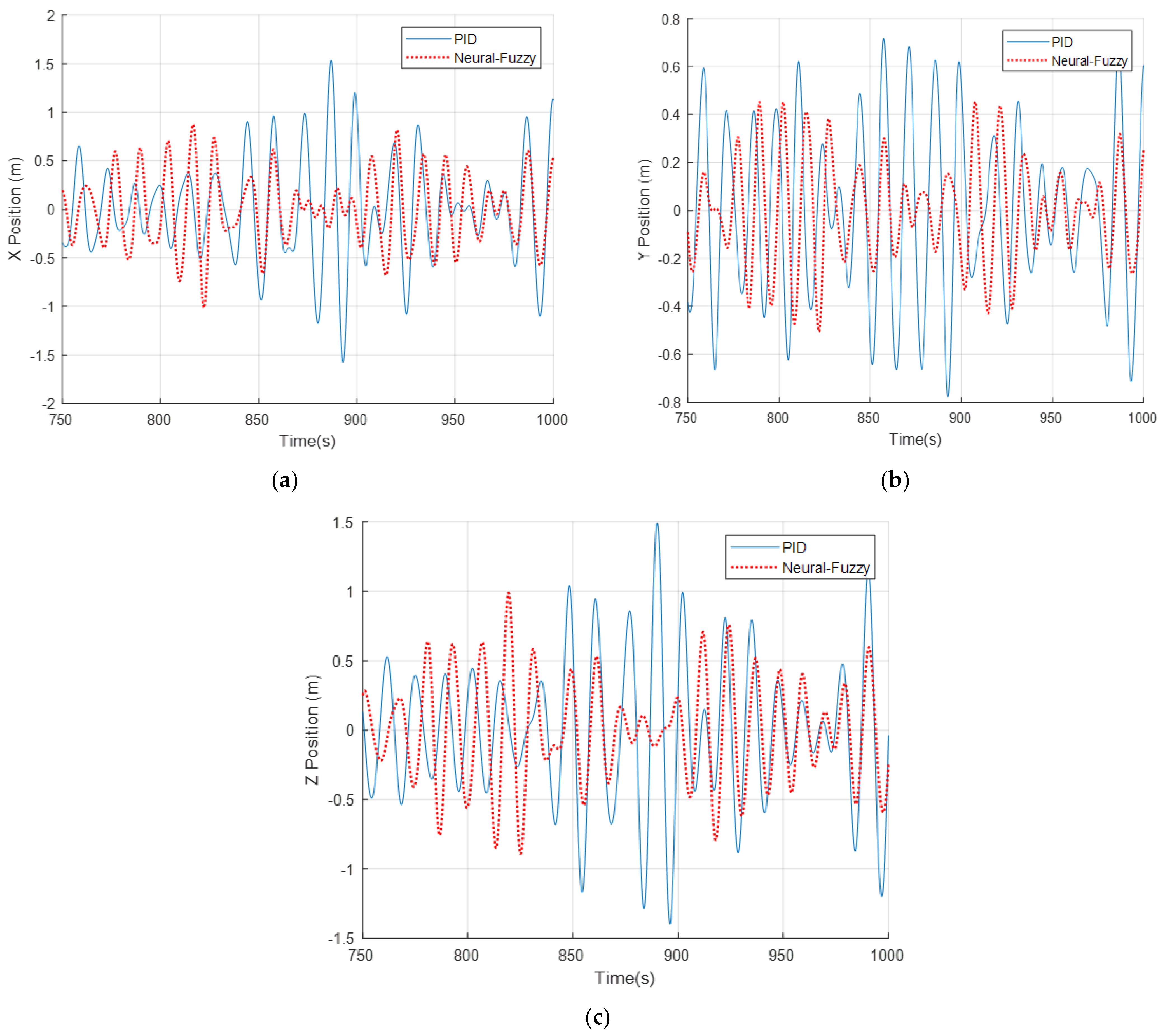
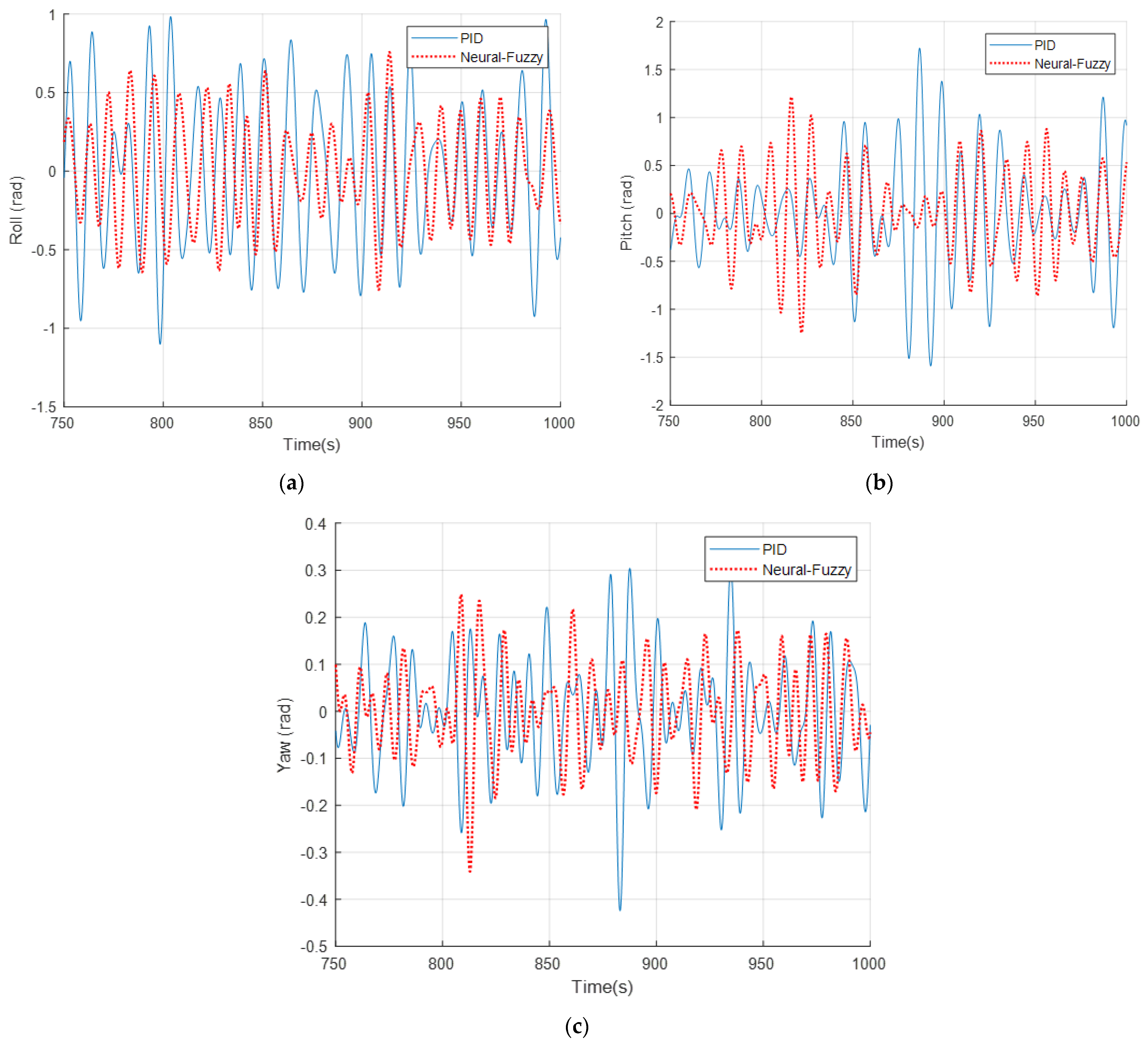
Figure 10 and
Figure 11 demonstrate that the ANFIS controller exhibits significantly greater stability compared to the PID controller. It is evident that both the position and angle exhibit smaller variations and are closer to the stability line. Based on these observations, it can be concluded that the ANFIS controller is more effective in maintaining the ship’s direction. Regardless of external factors such as wind, waves, and water flow, the ANFIS controller consistently demonstrates superior noise suppression capabilities compared to the PID controller. This stability, as indicated by the obtained results, positions the ANFIS controller as a favorable choice for ensuring stable ship control. To further assess its efficiency, the authors conducted simulations and evaluated the results based on speed parameters, which are presented below.
In
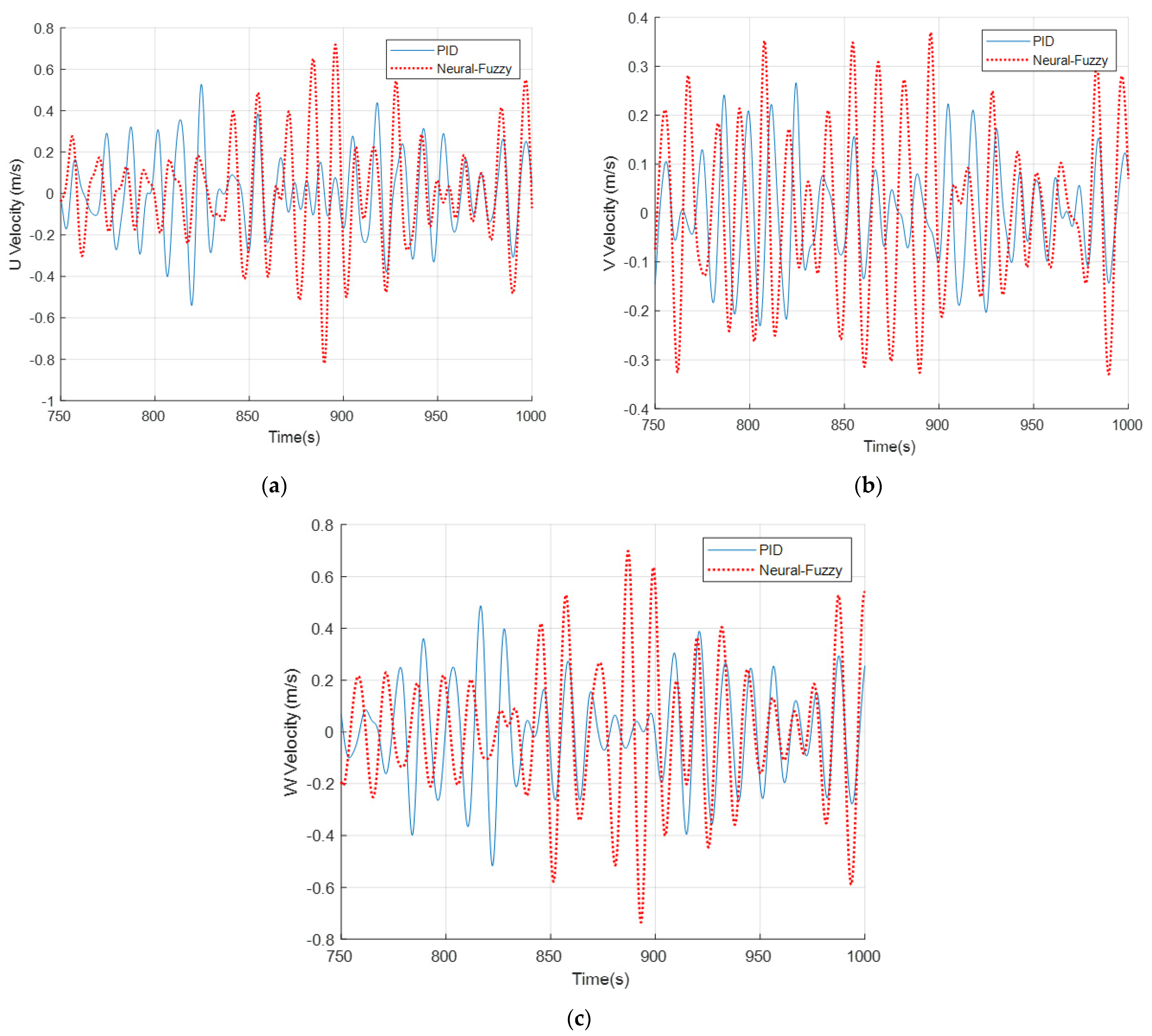
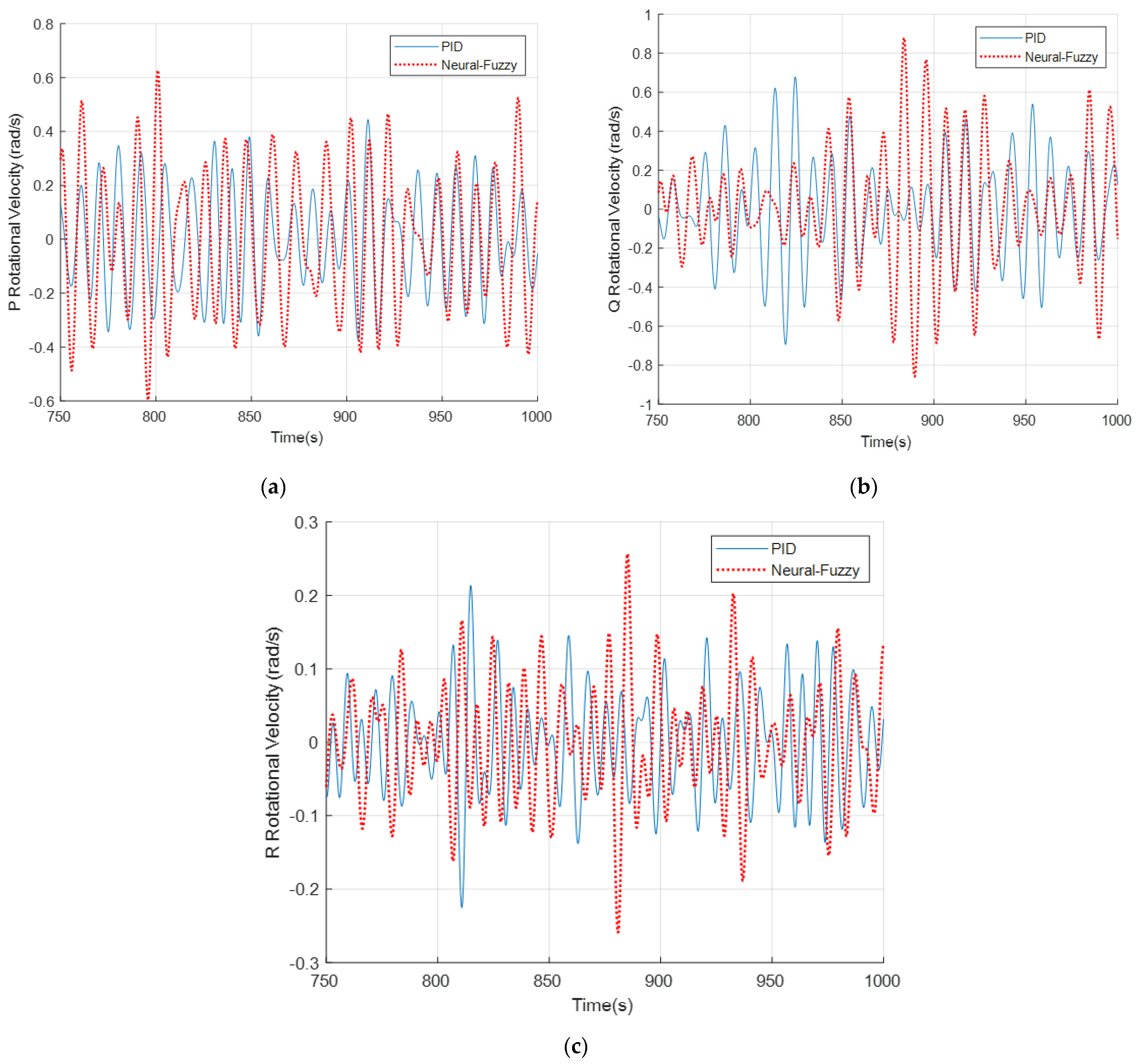
Figure 12 (vehicle speed along spatial axes) it is easy to see that the characteristic curves represent a larger amplitude speed and a shorter and more stable period representing a more highly responsive controller than the traditional PID controller. Similarly,
Figure 12 and
Figure 13 (the angular velocity of the ship in spatial coordinate axes) show that the speed response of the ANFIS controller is more efficient than the speed response of the PID controller. The speed controlled by the ANFIS controller has a larger amplitude than the speed controlled by the PID controller. This results in a faster response to noise and bias. From there, it can be seen that the ANFIS controller helps the ship to follow the trajectory better than the PID controller.
Since the input signal of the position and rotation angle set by the author is set, input = asin(0) + b is a straight line. When evaluating the stability, the initial amplitude, frequency, and phase angle of the input signal are evaluated, and the difference in the amplitude of the signal is compared to the set signal. From there, it can be seen that the signal of the ANFIS is more stable than that of the PID controller. In the simulation, the authors suppose that the input signal of position and rotation are sin (0).
Figure 10a shows that for the ANFIS controller, the peak of the smallest error approximates 0, and the peak of the largest error is around 0.8. The cycle from the peak of the smallest error to the peak of the largest error and back to the peak of the smallest error again is approximately 150 s. On the other hand, for the PID controller, the peak of the smallest error is close to zero, and the peak value of the largest error is approximately 1.5. The cycle for the error to reach a steady state again is 150 s. In
Figure 10b, the ANFIS controller has a minimum peak that is close to zero and a maximum peak of about 0.45. It runs along a straight line with zero slope. As for the PID controller, the minimum amplitude of the error is 0.1, while the maximum amplitude is approximately 0.8. In
Figure 10c, the ANFIS controller has a minimum peak error of around 0.1 and a maximum peak error of 1. On the other hand, the PID controller has a minimum peak error of about 0.1 and a maximum peak error of 1.5. It is evident that the difference in error between the ANFIS controller and the input signal is smaller compared to the PID controller. Similarly, in
Figure 11, it can be observed that the difference in the peak amplitude of the error for the PID controller compared to the setpoint signal is greater than that of the ANFIS controller. Hence, it can be concluded that the ANFIS controller provides better stability compared to the PID controller.
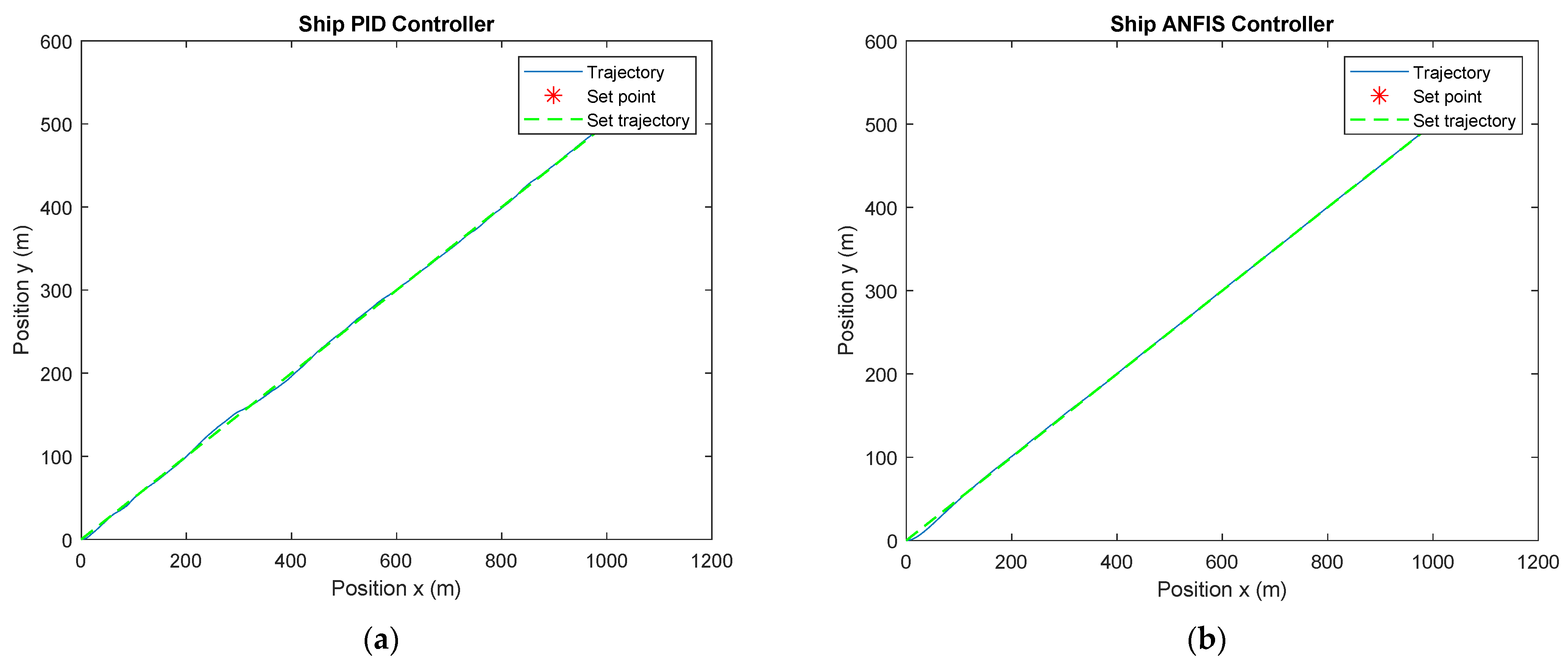
In order to verify the reliability of the controller, the authors conducted an additional simulation. This time, they simulated a single scenario that closely resembled the conditions of a real ship. The parameters used in the simulation were as follows: ship mass (m) = 10,000 kg, ship length (L) = 20 m, vessel width (B) = 5 m, and vessel depth (D) = 2 m. The initial velocity (v0) is 5 m/s, the initial rotation angle (psi0) is 0, the initial coordinates are (0,0), and the target destination coordinates are (1000, 500) operating under the influence of mild noise.
In
Figure 14, under the influence of mild noise, it is easy to observe that when both controllers are operating, the ANFIS controller closely matches the desired signal, while the PID controller may have some minor deviations, but they are not significant.
Regarding the speed signal [
42], the adaptability and fast response of the ANFIS controller can be seen. In both angular speed and speed, the response processing of the always-feedback speed of the ANFIS controller is higher than that of the PID controller.
According to the results obtained after simulation, it can be seen that the signals of waves, wind, and groundwater caused by the environment have been quickly suppressed thanks to the self-learning feature of the neural network and the fuzzy logic controller’s ability to argue so that the ship can operate more stably. However, there are some features worth discussing, such as:
Although the learning process is smart, it is still necessary to monitor whether or not it is going in the right direction needed for the problem.
Training time and computing resources are enormous, possibly up to several tens of gigabytes.
The research direction in this paper is an open direction that can study the mentioned issues more deeply for experimental verification and hope to get better results in the future.
Let us further examine the ANFIS controller when controlling a different object, as discussed in [
35]. It can be observed that the controller’s quality is similar for both objects, despite their differences. The intelligent controller, which combines a neural network and fuzzy logic control, is effective in eliminating noise and has a fast response. This controller enhances the tracking performance of the ship trajectory, in particular, and the control of other objects in general, making it stronger and more accurate than the PID controller.
To be able to see the effectiveness of the controller proposed in this study more clearly, compare it with some typical papers on ship control when applying fuzzy controllers [
37,
38,
39,
40]. In the standard articles in the above discussion of ship control using fuzzy controllers, an ANFIS (Adaptive Neuro-Fuzzy Inference System) controller is not normally used. However, the advantages and disadvantages of a fuzzy controller with an ANFIS controller can be compared as follows:
Advantages of a fuzzy controller:
- -
Simple and easy to deploy.
- -
Ability to handle nonlinear systems.
- -
Ability to handle noise and uncertainty.
- -
The ability to interact between input variables in a sensitive way.
Disadvantages of a fuzzy controller:
- -
It is necessary to design the fuzzy rules correctly to achieve the best performance.
- -
Difficulty in accurately evaluating the parameters of the fuzzy controller.
- -
The performance of the fuzzy controller can be reduced in the case of a complex nonlinear system.
Advantages of an ANFIS controller:
- -
Ability to combine neural networks and fuzzy set systems.
- -
Ability to learn and self-adjust the model’s parameters automatically.
- -
Ability to handle complex nonlinear systems.
Disadvantages of ANFIS controller:
- -
Requires a large amount of training data to achieve good results.
- -
Difficulty in understanding and explaining the learning process of the ANFIS model.
- -
Learning speed may be slower than other deep learning models.
In summary, both methods have their own pros and cons, but the ANFIS controller is normally more capable of handling complex nonlinear systems and automating the fine-tuning of the parameters than the fuzzy controller.
The ANFIS controller is an effective solution for ship control, providing stability and accuracy in maintaining the ship’s trajectory. The combination of an adaptive neural network and a fuzzy logic system in this controller enables the efficient handling of complex and uncertain factors in the ship control environment. Additionally, the learning and adjustment capabilities of the ANFIS controller enhance the flexibility and overall performance of the ship. Discussing the application and optimization of the ANFIS controller for ships holds great promise and potential in this field.

