Abstract
Underwater vehicles are a powerful tool that can assist oceanologists with measuring the state of oceans on a large scale. The heading control is essential for the underwater vehicle to follow a specific path. This study describes the general decoupled dynamics of underwater vehicles, which is a nonlinear second-order differential equation considering linear and quadratic damping hydrodynamics. A novel aspect of this study is the development of a new analytical solution for the second-order nonlinear differential equation, which involves the heading motion of the underwater vehicle. In this study, the time-optimal trajectory is formulated as the closed-form solution for the heading dynamics of the underwater vehicle. The concept of this trajectory is based on the shortest arrival time when the maximum force from the thrusters is applied to the underwater vehicle. Finally, a simulation of the time-optimal trajectory and evaluation of the robustness of the controller were demonstrated in order to verify the effectiveness of the proposed trajectory for controlling underwater vehicles.
1. Introduction
Although we have made significant strides in exploring the surface of the earth and outer space, we still have a limited understanding of the mysteries hidden in the depths of the ocean. The ocean is home to a vast array of natural and mineral resources, and with the depletion of resources on land, there is an increasing demand to explore the ocean’s wealth. The ocean covers approximately 70% of the earth’s surface area, making it a valuable source of untapped resources. As the global population and resource consumption continue to grow, there is a growing need to focus on the ocean. Unfortunately, current techniques for undersea development are limited and challenging. As a result, there is a significant push to develop advanced oceanographic systems to explore and exploit the vast oceanic environment. Underwater vehicles (UVs) have been developed for a diverse range of tasks, with a variety of types available. Examples include Autonomous Underwater Vehicles (AUVs) [1,2], Remotely Operated Vehicles (ROVs) [3,4], and underwater gliders (UGs) [5,6], among others. Underwater vehicles have been used as advanced vehicles for marine security, mineral reconnaissance, and military surveillance [7,8,9,10,11,12].
Trajectories are essential for controlling the motion of autonomous systems, and their design is crucial for achieving high performance. If we want the controller to perform efficiently, we need to optimize the trajectory for both time and energy efficiency. In order to achieve good controllability, the set of desired points should consider many constraints, such as actuation saturation and energy consumption. There are various methods for designing trajectories, and one of the simplest ones is to use a low-pass filter or a polynomial function to smoothly connect the start and end points. In 2003, Fraga et al. [13] proposed a low-pass filter that allows for the creation of simple trajectories using a constant destination depth or a polynomial function to smoothly connect the departure point and destination. However, while these trajectories are easy to design, they may not be the most efficient in terms of time or energy consumption. To optimize their performance, more complex trajectory planning methods can be used. These methods take into account factors such as minimum time or energy consumption while ensuring the trajectory is feasible and smooth. Although these methods may require more computational resources, they can result in significant improvements to the overall performance of the system. Therefore, the use of advanced trajectory planning methods should be considered for systems where time and energy efficiencies are crucial. In recent years, a number of studies on the time-optimal trajectory of underwater vehicles have been published. Chyba et al. [14] described the time-optimal trajectory in terms of a singular extremal of the dynamics of both fully actuated and under-actuated underwater vehicles. In a later study [15], a numerical solution of the time-optimal trajectory was applied to a spherical underwater vehicle, and a long computing time was indicated as a limitation of this algorithm. Moreover, the time-optimal trajectory was studied in [16] for an underwater glider in the known and time-varying flow fields. In addition, the explicit solution of the time-optimal trajectory for the depth control of the underwater vehicle was studied [17]. Vu et al. [18] designed an energy-efficient trajectory for the depth motion control of an underwater vehicle system with the uncertainty of bounded parameters and disturbances within limited control input using the global optimal sliding mode controller. However, the depth dynamics were simplified by neglecting the linear damping coefficient (only the quadratic term was considered), and only a positive domain trajectory was formulated.
Ocean engineering researchers find developing controllers for this type of robot to be an engaging subject. In particular, the heading control is one of the more important issues, indispensable to any UV. Proportional-Integral-Derivative (PID) controllers are widely used due to their simplicity and easy implementation, as stated by [19]. However, controlling unmanned underwater vehicles (UUVs) for various tasks and missions poses several challenges due to the highly coupled nonlinear models, time-varying dynamic models, and external disturbances from sea currents and waves, which can lead to unpredictable underwater currents. These challenges have been discussed in detail in [20,21,22]. Consequently, the limitations of PID techniques in dealing with uncertainties, especially in the case of model uncertainty, have become apparent. Such limitations can result in the severe degradation of the controller’s performance, leading to instability or poor tracking. To overcome these limitations, it is essential to develop alternative control techniques that can handle model uncertainties and provide better robustness and performance. In recent years, various advanced control strategies have been proposed to enhance the dynamic performance of UVs, including linear controllers [23,24], fuzzy logic control [25,26], sliding mode control (SMC) [27,28], predictive control algorithms [29,30], and neural network control strategies [31]. These techniques have shown promising results in improving the robustness and performance of the controller, making them potential alternatives to PID control strategies.
This study focused on examining the independent movement patterns of underwater vehicles through the analysis of their decoupled dynamics. To achieve this, we presented a second-order nonlinear differential equation that incorporated hydrodynamic forces, specifically linear and quadratic damping. The paper introduces a new analytical solution for this equation, which involves the heading motion of the underwater vehicle. The study formulates a time-optimal trajectory that considers the closed-form solution for the heading dynamics of the underwater vehicle. The trajectory is designed to achieve the shortest arrival time form when the maximum force from the thrusters is applied to the vehicle. In addition, a chattering-free robust controller is also discussed using a sliding mode controller and super-twisting controller. The proposed trajectory is then evaluated through a simulation to demonstrate its effectiveness in controlling underwater vehicles.
The rest of this paper is organized as follows. In Section 2, we introduce the dynamics of an underwater vehicle, with a particular focus on its decoupled yaw dynamic. Section 3 presents a closed-form solution for the time-optimal trajectory of the underwater vehicle‘s yaw motion, followed by the design of robust tracking controls using a sliding mode control (SMC) and super-twisting SMC in Section 4. Section 5 reports on numerous numerical simulations and a discussion of the results obtained using the proposed time-optimal trajectory (TOT) and robust controller. Finally, we conclude by presenting the effectiveness of the proposed TOT and the benefits of the closed-form solution.
2. Dynamics of an Underwater Vehicle
2.1. Assumptions
This paper investigated the autonomous heading planning of an underwater vehicle for ocean exploration by designing a time-optimal trajectory and robust control method. We utilized the dynamic equations of the underwater vehicle in the design process of the time optimal trajectories and proposed controller. To clarify the research issues, we established the following assumptions and constraints:
- The underwater vehicle has neutral buoyancy, and its body-fixed coordinate system is centered at the center of mass;
- The underwater vehicle is a rigid body with no bending or geometrical deformations;
- The underwater vehicle is deeply submerged in a homogeneous, unbounded fluid, far from the free surface and without surface effects;
- The underwater vehicle has three planes of symmetry;
- The propeller provides constant thrust, and its torque is negligible and ignored;
- We mainly study the heading motion of the underwater vehicle in the horizontal plane and simplify the model to a degree of freedom model by ignoring the roll, pitch, and heave motions of the underwater vehicle.
2.2. Heading Motion of Underwater Vehicle
The motion of an underwater vehicle is typically described as free movement in six degrees of freedom (6-DOF). This involves developing both kinematic and kinetic models. To obtain dynamic equations for an underwater vehicle, two coordinate systems were utilized, as shown in Figure 1. The Earth-fixed coordinate system (O_NDE) was used to represent the global reference frame while the body-fixed coordinate system (O_XYZ) was attached to the center of buoyancy of the underwater vehicle. The body-fixed coordinate system used the longitudinal axis (x-direction) to represent the direction from the stern to the bow, the transverse axis (y-direction) for the direction to the starboard, and the normal axis (z-direction) to represent the direction from top to bottom. The 6-DOF equations of motion without control inputs of a fully submerged underwater vehicle whose body axes coincide with the principal axes of inertia can be written as shown in Equations (1)–(3), as presented by [32].
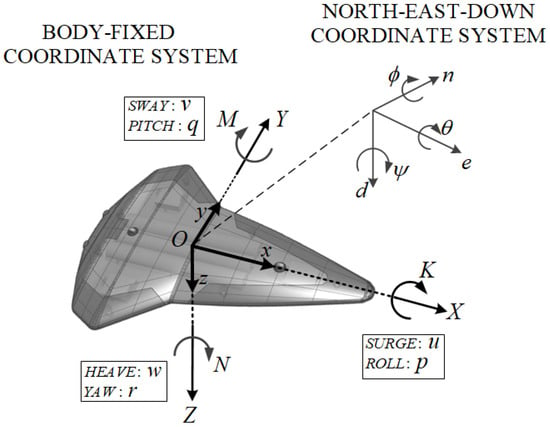
Figure 1.
Schematic diagram defining the coordinate system of underwater vehicle.
Here, are linear velocities of origin O in the body-fixed frame with respect to the North, East, Down (NDE) coordinates (n, e, d, respectively) shown in Figure 1; are angular velocities of a body-fixed frame with respect to the NDE coordinate system; are Euler angles; are body-fixed forces; are body-fixed moments; are added mass coefficients; are linear damping coefficients; are quadratic damping coefficients; are the center coordinates of gravity in the body-fixed frame; and are the center coordinates of buoyancy in the body-fixed frame.
The decoupled yaw dynamics of the underwater vehicle can be written as shown in Equation (4) [33].
where is the yaw rate; is the moment of inertia about the Z-axis; is the added mass coefficient; are the linear and quadratic damping coefficients, respectively; is the torque of the thrusters; and is an external disturbance. For simplicity, Equation (4) can be rewritten as follows:
where
3. Time-Optimal Solution of the Second-Order Differential Equation
To get the general closed-form solution of the second-order differential equation representing the underwater heading motion, the disturbance term in Equation (5) was neglected. The heading dynamics without disturbance is described in Equation (7), where
In order to find the solution for the dynamics in Equation (7), the sign of r should be specified. The solutions were constructed in the positive and negative velocity domains, as shown in Appendix A and Appendix B, respectively. In order to simplify the time-optimal solution, only the positive velocity was considered here. The negative domain can be solved in a similar manner as the positive domain in Appendix B. When is given, Equation (7) can be rewritten as Equation (8) or Equation (9), which is a solvable dynamic, where is the designed trajectory of heading velocity for the tracking controller.
The strategy of TOT uses the maximum input to increase the velocity to the critical value and then uses the minimum torque to decrease the velocity to zero such that all position and velocity constraints in Figure 2 are satisfied. This concept was first proposed in [17]. There are three time periods in the TOT trajectory analysis, acceleration, constant velocity, and deceleration periods where the corresponding control inputs are equal to , , and 0, respectively (Figure 2a). Equation (9) has different c values for different periods, resulting in solutions for the heading dynamic as summarized in Equations (10)–(18). The solutions for the acceleration, constant velocity, and deceleration period can be solved following Appendix A.
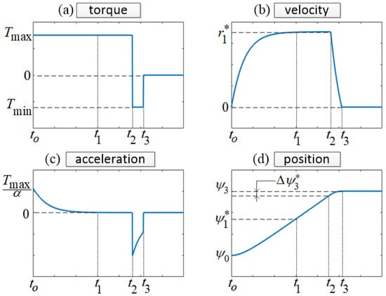
Figure 2.
Trajectory profiles. (a) Torque, (b) velocity, (c) acceleration, and (d) position curves.
3.1. Acceleration Period ():
3.2. Constant Velocity Period ():
3.3. Deceleration Period ():
3.4. Closed-Form Solution for TOT Trajectory
The initial position and velocity constraints in the TOT trajectories were defined as shown in Equations (19) and (20), Figure 2b,d.
The final position and velocity constraints in the TOT trajectories were defined as shown in Equations (21) and (22).
The following describes how we calculated the critical values and shown in Figure 2d. If the difference between the final and initial position was greater than the summation of and , TOT was shown as the closed-form solution. Otherwise, TOT was found using a numerical method. Here, the closed-form solution of the TOT was given for the condition .
The maximum positive velocity was found using Equation (13), and then, the time for reaching this critical velocity was defined as follows:
where
The critical value can be calculated using:
where
Then, the second critical value can be derived from Equations (27)–(30).
Finally, the solutions of the TOT trajectory can be easily derived, as shown in Equations (31)–(33).
4. Super-Twisting Sliding Mode Control
This section describes the implementation of the super-twisting sliding mode control (ST-SMC) algorithm for the underwater vehicle depicted in Figure 3, which is utilized for tracking control purposes.

Figure 3.
Underwater vehicle heading control scheme using super-twisting sliding mode control algorithm.
The SMC adopts a sliding surface formulation, which is expressed in terms of the error, as demonstrated in Equation (34).
where s represents a scalar value while denotes the desired yaw rate; refers to the heading angle; is the desired heading angle; and finally, represents the weight factor for the sliding surface, and it is a positive value.
The fundamental objective of SMC is to maintain s at a zero value, which corresponds to achieving zero errors in both position and velocity, as described in [34]. As s approaches zero, it is necessary to keep its value close to zero, which requires the derivative of s to be zero. This can be mathematically expressed as follows:
In order to compute the control input required to bring to zero, Equation (5) is substituted into Equation (35), which yields the resulting Equation (36).
The Filippov theory provides an optimal estimation of the equivalent control, which does not account for external disturbances or uncertainties. This estimation can be obtained by employing Equation (36). Subsequently, the actual sliding mode control law can be expressed as follows:
The expression for the actual sliding mode control law involves two key parameters, namely and . The parameter represents the estimated value of parameter while refers to the discrete control or switching control. Two different types of switching laws are presented in Equations (38) and (39), which correspond to the conventional sign function and super-twisting algorithm, respectively. The controller gains are denoted by K, , and .
where the function sign(.) represents the signum function, which is defined as:
For reducing the chattering effect, the sign function in Equations (38) and (39) is replaced by the saturating function as shown in Figure 7.6.b in [34] as follows:
where is the boundary layer thickness of the saturating function, which can be used to effectively reduce the chattering in the sliding mode control.
The Lyapunov function (42) is commonly chosen in sliding mode control. The derivative of V can be calculated by multiplying the sliding surface and its derivative, as demonstrated in Equation (43).
In order to ensure the derivative of V is a negative definite, we defined the control gain K for SMC and the control gains and for ST-SMC using Equations (44) and (45).
where
5. Computer Simulation
Simulating the combination of time-optimal trajectory and ST-SMC for an underwater vehicle was a challenging task because of the system’s poor damping and the highly nonlinear and complex dynamics, which were further compounded by model uncertainties and external disturbances. In this section, the numerical simulations based on MATLAB/Simulink environments are performed to evaluate the effectiveness of combining the time-optimal trajectory and ST-SMC. The following three simulations have been performed as:
- Simulation 1: TOT trajectory with tracking SMC controller without uncertainties.
- Simulation 2: TOT trajectory with tracking SMC controller under parameter uncertainties and external disturbances ().
- Simulation 3: TOT trajectory with tracking ST-SMC controller under higher parameter uncertainties and external disturbances ().
The heading dynamic parameters and controller gains used in three simulations were as follows ; ; ; ; ; ; ; ; (first and second simulation); (third simulation). Therefore, the estimated values , , and can be calculated using the definition in Equation (5) with the above parameters.
For the second and third simulations, the uncertainties and disturbance could be given as follows: ; ; ; .
Assuming that the inertia term can be accurately measured using the pendulum table and the hydrodynamic term is typically estimated using the CFD method, in our model, it is appropriate to assign a 20% uncertainty to the inertial term and an 80% uncertainty to the other hydrodynamic terms to account for the limitations of measurement and estimation methods. Thus, the uncertainty values for α, a, and b were 20%, 80%, and 80%, respectively.
5.1. Simulation 1
In this simulation, the perfect knowledge of the parameters and absence of disturbances in the heading dynamic were assumed to evaluate the combination of TOT and SMC control. The first simulation described the SMC of the TOT trajectory without considering the uncertainties; the results are shown in Figure 4. The tracking control successfully followed the TOT trajectory, and the designed torque was fully used in the bounded input range as shown in Figure 4a. Because the control input were the maximum and minimum values for acceleration and deceleration periods, respectively, the total time to the final position was the minimum arrival time. Figure 4b–d demonstrate excellent tracking performance for the position, velocity, and acceleration, respectively, validating the effectiveness of the SMC and TOT trajectory combination. However, in practical applications, system parameters were typically estimated with some degree of inaccuracy, and environmental disturbances were unavoidable. Thus, to fully evaluate the proposed trajectory and controller, we conducted the second and third simulations under conditions of parameter uncertainties and external disturbances.
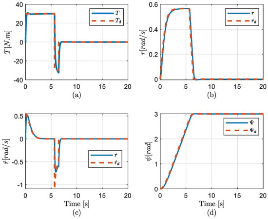
Figure 4.
TOT and SMC without uncertainties (a) Torque, (b) Velocity, (c) Acceleration, and (d) Position curves in simulation 1.
5.2. Simulation 2
In real applications, parameter uncertainties and external disturbances always exist. This simulation aimed to evaluate the robustness of the proposed TOT trajectory with the SMC controller against parameter uncertainty and external disturbance. In the second simulation, an external disturbance was added to the system from 10 s to 15 s, providing a clear analysis of the impact of parameter uncertainty and disturbance. Figure 5 displays the tracking performance of the TOT trajectory and SMC controller in this simulation. The simulation results demonstrated that the acceleration, velocity, and yaw angle of the underwater vehicle closely followed the designed trajectories. However, since the uncertainties were sinusoidal, the control force also oscillated sinusoidally to minimize their impact. Consequently, the acceleration and velocity oscillated around the designed trajectories. During the disturbance period (10 s to 15 s), the acceleration exhibited a waveform pattern as a result of the wave-formed disturbance, which can also be observed in Figure 6. However, the velocity and position error were small, as shown in the sliding surface quantity, which was smaller than 0.06 (Figure 6). The disturbance resulted in the small amplitude oscillation from 10 s to 15 s in Figure 6. Hence, the SMC controller could overcome parameter uncertainties and environmental disturbances in this case.
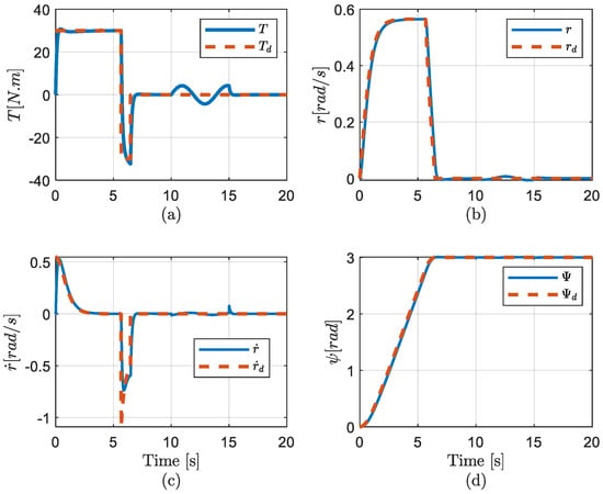
Figure 5.
TOT and SMC with uncertainties and (a) Torque, (b) Velocity, (c) Acceleration, and (d) Position curves in simulation 2.
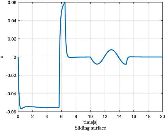
Figure 6.
Sliding surface in SMC in simulation 2.
5.3. Simulation 3
Chattering is one of the most common issues encountered in sliding mode control and must be eliminated for the controller to perform effectively. The use of the saturation function successfully eliminates the chattering effect, leading to an improved controller performance. Therefore, in this study, this chattering problem could be minimized by using a saturation function, which had a trade-off related to higher errors. To address this issue, a high-order switching technique was utilized in this simulation. With this approach, the performance of the designed controller was improved without sacrificing tracking error quality, as compared to the SMC case (Figure 7). In the third simulation, using the same conditions as in the second simulation (i.e., with parameter uncertainty and a wave-formed disturbance), ST-SMC was applied to the tracking control using the controller gains shown in Equation (45). The tracking performance in the velocity and position were similar to those calculated in the second simulation. Overall, the controller helped the vehicle achieve a smooth movement towards the desired heading angle with minimal energy consumption, as depicted in Figure 7. The results indicate that the controller performed well even in the presence of high uncertainties. In Figure 7, it can be observed that the control input and acceleration of the ST-SMC controller were much smoother than those of the SMC controller. The tracking error was shown in terms of the sliding surface, which was smaller than 0.055 (Figure 8). In addition, the chattering problem was reduced dramatically using ST-SMC (Figure 7a) compared with using SMC (Figure 5a). These results indicate that the ST-SMC controller was more effective than the SMC controller in reducing the chattering phenomenon while maintaining the tracking performance.
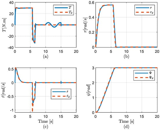
Figure 7.
TOT and ST-SMC with uncertainties and (a) Torque, (b) Velocity, (c) Acceleration, and (d) Position curves in simulation 3.
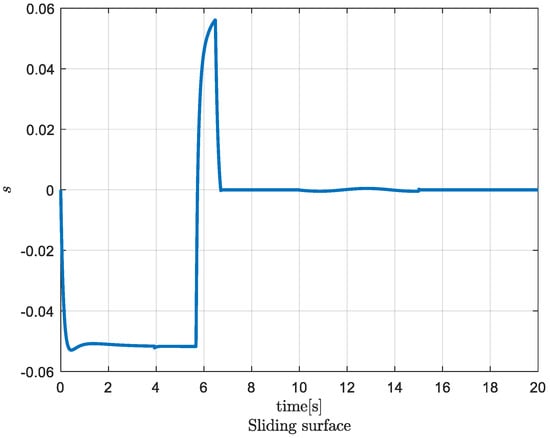
Figure 8.
Sliding surface in ST-SMC in simulation 3.
6. Conclusions
The study investigated the general decoupled dynamics of underwater vehicles; we described a nonlinear second-order differential equation considering linear and quadratic damping hydrodynamics. In particular, a new analytical solution for the second-order nonlinear differential equation was presented that described the heading motion of the underwater vehicle. The time-optimal trajectory was formulated in a closed-form solution that was used for the decoupled heading dynamics considering all hydrodynamic coefficients. In order to control the heading of the underwater vehicle following the time-optimal trajectory, conventional and second-order SMC were derived based on the Lyapunov theory. If the controller can track the proposed time-optimal trajectory, the fastest arrival time can be fulfilled. The combination of the proposed trajectory and the tracking control was validated using simulations. Two effective tracking controllers were described to track the time-optimal trajectory, and the chattering phenomenon of the conventional SMC was significantly reduced by using a super-twisting SMC while maintaining a similar error.
The main limitation of this study is that it lacks verification through corresponding mode tests. To address this, future research will prioritize the development of model tests and additional mathematical model verification. Additionally, our study focused on the time-optimal trajectory and tracking problem of coordinated displacements on the heading motion of underwater vehicles. To further enhance the capabilities of these vehicles, our future research will focus on designing a robust controller and time-optimal trajectory for pitch and depth motions. We believe that this will further enhance the capabilities of underwater vehicles and make them more effective in a variety of applications.
Author Contributions
Conceptualization, N.-D.N., M.T.V. and H.-S.C.; methodology, P.N.; software, D.-W.J.; validation, M.T.V., J.H., P.H.N.A., P.N. and N.-D.N.; formal analysis, N.-D.N. and H.-S.C.; investigation, H.-S.C. and M.T.V.; resources, N.-D.N. and M.T.V.; data curation, J.H. and P.H.N.A.; writing—original draft preparation, N.-D.N. and M.T.V.; writing—review and editing, M.T.V., N.-D.N., P.N., H.C. and D.-W.J.; supervision, H.-S.C. and M.T.V.; project administration, H.-S.C.; funding acquisition, H.-S.C. All authors have read and agreed to the published version of the manuscript.
Funding
This research was supported by the Unmanned Vehicles Core Technology Research and Development Program through the National Research Foundation of Korea (NRF) and Unmanned Vehicle Advanced Research Center (UVARC), funded by the Ministry of Science and ICT, the Republic of Korea, (NRF-2020M3C1C1A02086321) and, also supported by Development of Biomimetic Underwater Undulating Robot funded by the Agency of Defence Development.
Institutional Review Board Statement
Not applicable.
Informed Consent Statement
Not applicable.
Data Availability Statement
Not applicable.
Conflicts of Interest
The authors declare no conflict of interest.
Appendix A. Solution of Heading Dynamics in the Positive Domain
Appendix A.1. Acceleration Period:
Because
where ;
From (A2) and (A3), we have:
From (A3) and , we have:
From (A4), we have:
From (A6) and , we have:
Acceleration solution is as follows:
Appendix A.2. Constant Velocity Period:
The velocity and position solution in this period can be easily derived as follows:
where
Two critical values of time and position are defined as below:
Appendix A.3. Deceleration Period:
Let us define the value as below:
Appendix A.3.1. If
Appendix A.3.2. If
Appendix B. Solution of Heading Dynamics in the Negative Domain
Appendix B.1. Acceleration Period:
Because
where ; .
The solutions of are similar to (A4), (A6) and (A8), respectively.
Appendix B.2. Constant Velocity Period:
The solutions of are similar to (A9) and (A10), respectively.
Appendix B.3. Deceleration Period:
Appendix B.3.1. If
The solutions of are the same as (A16), (A18) and (A20), respectively.
Appendix B.3.2. If
The solutions of are the same as (A22), (A24) and (A26), respectively.
References
- Vu, M.T.; Choi, H.S.; Thieu, Q.M.N.; Nguyen, N.D.; Lee, S.D.; Le, T.H.; Sur, J. Docking assessment algorithm for autonomous underwater vehicles. Appl. Ocean Res. 2020, 100, 102180. [Google Scholar] [CrossRef]
- Cho, H.; Jeong, S.-K.; Ji, D.-H.; Tran, N.-H.; Vu, M.T.; Choi, H.-S. Study on Control System of Integrated Unmanned Surface Vehicle and Underwater Vehicle. Sensors 2020, 20, 2633. [Google Scholar] [CrossRef] [PubMed]
- Kang, J.I.; Choi, H.S.; Vu, M.T.; Nguyen, N.D.; Ji, D.H.; Kim, J.Y. Experimental study of dynamic stability of underwater vehicle-manipulator system using zero moment point. J. Mar. Sci. Technol. Taiwan 2017, 25, 767–774. [Google Scholar]
- Vu, M.T.; Thanh, H.L.N.N.; Huynh, T.T.; Do, Q.T.; Do, T.D.; Hoang, Q.D.; Le, T.H. Station-Keeping Control of a Hovering Over-Actuated Autonomous Underwater Vehicle Under Ocean Current Effects and Model Uncertainties in Horizontal Plane. IEEE Access 2021, 09, 6855–6867. [Google Scholar] [CrossRef]
- Deutsch, C.; Kuttenkeuler, J.; Melin, T. Glider performance analysis and intermediate-fidelity modelling of underwater vehicles. Ocean Eng. 2020, 210, 107567. [Google Scholar] [CrossRef]
- Jeong, S.K.; Choi, H.S.; Ji, D.H.; Vu, M.T.; Kim, J.Y.; Hong, S.M.; Cho, H.J. A study on an accurate underwater location of hybrid underwater gliders using machine learning. J. Mar. Sci. Technol.-Taiwan 2020, 28, 518–527. [Google Scholar]
- Vu, M.T.; Choi, H.S.; Nguyen, N.D.; Kim, S.K. Analytical design of an underwater construction robot on the slope with an up-cutting mode operation of a cutter bar. Appl. Ocean Res. 2019, 86, 289–309. [Google Scholar] [CrossRef]
- Chen, M.Z.; Guo, S.X.; Zhu, D.Q. Motion planning for an under-actuated autonomous underwater vehicle based on fast marching nonlinear model-predictive quantum particle swarm optimization. Ocean Eng. 2023, 268, 113391. [Google Scholar] [CrossRef]
- Vu, M.T.; Choi, H.S.; Ji, D.H.; Jeong, S.K.; Kim, J.Y. A study on an up-milling rock crushing tool operation of an underwater tracked vehicle. Proc. Inst. Mech. Eng. Part M-J. Eng. Marit. Environ. 2019, 233, 283–300. [Google Scholar] [CrossRef]
- Li, J.J.; Xiang, X.B.; Dong, D.L.; Yang, S.L. Prescribed time observer based trajectory tracking control of autonomous underwater vehicle with tracking error constraints. Ocean Eng. 2023, 274, 114018. [Google Scholar] [CrossRef]
- Vu, M.T.; Van, M.; Bui, D.H.P.; Do, Q.T.; Huynh, T.T.; Lee, S.D.; Choi, H.S. Study on Dynamic Behavior of Unmanned Surface Vehicle-Linked- Unmanned Underwater Vehicle System for Underwater Exploration. Sensors 2020, 20, 1329. [Google Scholar] [CrossRef]
- Zhang, B.B.; Ji, D.; Liu, S.; Zhu, S.K.; Xu, W. Autonomous Underwater Vehicle navigation: A review. Ocean Eng. 2023, 273, 113861. [Google Scholar] [CrossRef]
- Fraga, S.L.; Sousa, J.B.; Pereira, F.L. Trajectory generation for a remotely operated vehicle. In Proceedings of the IEEE European Control Conference, Cambridge, UK, 1–4 September 2003. [Google Scholar]
- Chyba, M.; Leonard, N.E.; Sontag, E.D. Time-Optimal Control for Underwater Vehicles. IFAC Proc. Vol. 2000, 33, 117–122. [Google Scholar] [CrossRef]
- Chyba, M.; Haberkorn, T.; Smith, R.N.; Choi, S.K. Design and implementation of time efficient trajectories for autonomous underwater vehicles. Ocean Eng. 2008, 35, 63–76. [Google Scholar] [CrossRef]
- Rhoads, B.; Mezić, I.; Poje, A.C. Minimum time heading control of underpowered vehicles in time-varying ocean currents. Ocean Eng. 2013, 66, 12–31. [Google Scholar] [CrossRef]
- Loc, M.B.; Choi, H.S.; You, S.S.; Huy, T.N. Time optimal trajectory design for unmanned underwater vehicle. Ocean Eng. 2014, 89, 69–81. [Google Scholar] [CrossRef]
- Vu, M.T.; Choi, H.S.; Kang, J.I.; Ji, D.H.; Joong, H. Energy efficient trajectory design for the underwater vehicle with bounded inputs using the global optimal sliding mode control. J. Mar. Sci. Technol.-Taiwan 2017, 25, 705–714. [Google Scholar]
- Guerrero, J.; Torres, J.; Creuze, V.; Chemori, A.; Campos, E. Saturation based nonlinear PID control for underwater vehicles: Design, stability analysis and experiments. Mechatronics 2019, 61, 96–105. [Google Scholar] [CrossRef]
- Vu, M.T.; Le, T.H.; Thanh, H.L.N.N.; Huynh, T.T.; Van, M.; Hoang, Q.D.; Do, Q.T. Robust Position Control of an Over-actuated Underwater Vehicle under Model Uncertainties and Ocean Current Effects Using Dynamic Sliding Mode Surface and Optimal Allocation Control. Sensors 2021, 21, 747. [Google Scholar] [CrossRef]
- Antonelli, G.; Fossen, T.I.; Yoerger, D.R. Underwater Robotics; Springer Handbook of Robotics: Berlin/Heidelberg, Germany, 2008; pp. 987–1008. [Google Scholar]
- Vu, M.T.; Jeong, S.K.; Choi, H.S.; Oh, J.Y.; Ji, D.H. Study on down-cutting ladder trencher of an underwater construction robot for seabed application. Appl. Ocean Res. 2018, 71, 90–104. [Google Scholar] [CrossRef]
- Farrell, J.A.; Pang, S.; Li, W.; Arrieta, R.M. Biologically inspired chemical plume tracing demonstrated on an autonomous underwater vehicle. In Proceedings of the 2004 IEEE International Conference on Systems, Man and Cybernetics, Hague, The Netherlands, 10–13 October 2004. [Google Scholar]
- Yildiz, Ö.; Gökalp, R.B.; Yilmaz, A.E. A review on motion control of the underwater vehicles. In Proceedings of the 2009 International Conference on Electrical and Electronics Engineering-ELECO 2009, Bursa, Turkey, 5–8 November 2009. [Google Scholar]
- Jun, S.W.; Lee, H.J. Design of TS fuzzy-model-based controller for depth control of autonomous underwater vehicles with parametric uncertainties. In Proceedings of the 2011 11th International Conference on Control, Automation and Systems, Gyeonggi-do, Republic of Korea, 26–29 October 2011. [Google Scholar]
- Dahmani, H.; Chadli, M.; Rabhi, A.; El Hajjaji, A. Road curvature estimation for vehicle lane departure detection using a robust Takagi–Sugeno fuzzy observer. Veh. Syst. Dyn. 2013, 51, 581–599. [Google Scholar] [CrossRef]
- Mobayen, S.; Bayat, F.; Din, S.U.; Vu, M.T. Barrier function-based adaptive nonsingular terminal sliding mode control technique for a class of disturbed nonlinear systems. ISA Trans. 2023, 134, 481–496. [Google Scholar] [CrossRef] [PubMed]
- Alattas, K.A.; Vu, M.T.; Mofid, O.; ElSousy, F.F.M.; Fekih, A.; Mobayen, S. Barrier Function-Based Nonsingular Finite-Time Tracker for Quadrotor UAVs Subject to Uncertainties and Input Constraints. Mathematics 2022, 10, 1659. [Google Scholar] [CrossRef]
- Medagoda, L.; Williams, S.B. Model predictive control of an autonomous underwater vehicle in an in situ estimated water current profile. In Proceedings of the 2012 Oceans-Yeosu, Yeosu, Republic of Korea, 21–24 May 2012. [Google Scholar]
- Steenson, L.V. Experimentally Verified Model Predictive Control of a Hover-Capable AUV. Ph.D. Thesis, University of Southampton, Southampton, UK, 2013. [Google Scholar]
- Kumar, N.; Panwar, V.; Sukavanam, N.; Sharma, S.P.; Borm, J.-H. Neural network-based nonlinear tracking control of kinematically redundant robot manipulators. Math. Comput. Model 2011, 53, 1889–1901. [Google Scholar] [CrossRef]
- Fossen, T.I. Guidance and Control of Ocean Vehicles; John Wiley & Sons: New York, NY, USA, 1994. [Google Scholar]
- Bartolini, G.; Orani, N.; Pisano, A.; Punta, E.; Usai, E. A combined first-/second-order sliding-mode technique in the control of a jet-propelled vehicle. Int. J. Robust Nonlinear Control 2008, 18, 570–585. [Google Scholar] [CrossRef]
- Slotine, J.J.; Li, W. Applied Nonlinear Control; Prentice Hall: Hoboken, NJ, USA, 1991. [Google Scholar]
Disclaimer/Publisher’s Note: The statements, opinions and data contained in all publications are solely those of the individual author(s) and contributor(s) and not of MDPI and/or the editor(s). MDPI and/or the editor(s) disclaim responsibility for any injury to people or property resulting from any ideas, methods, instructions or products referred to in the content. |
© 2023 by the authors. Licensee MDPI, Basel, Switzerland. This article is an open access article distributed under the terms and conditions of the Creative Commons Attribution (CC BY) license (https://creativecommons.org/licenses/by/4.0/).