Article

A Concept Study on Design Alternatives for Minimizing Accident Consequences in Maritime Autonomous Surface Ships

1
Advanced Ship Research Division, KRISO, Daejeon 34103, Republic of Korea
2
Korea Autonomous Surface Ship Project Office, Daejeon 34103, Republic of Korea
3
Alternative Fuels and Power System Research Center, KRISO, Daejeon 34103, Republic of Korea
*
Author to whom correspondence should be addressed.
J. Mar. Sci. Eng. 2023, 11(5), 907; https://doi.org/10.3390/jmse11050907
Submission received: 29 March 2023 / Revised: 20 April 2023 / Accepted: 22 April 2023 / Published: 24 April 2023

Abstract

:
Autonomous ships, also known as maritime autonomous surface ships (MASS), are vessels that use artificial intelligence and robotics technologies to navigate independently. Due to their advanced technological capabilities, MASS is expected to play a significant role in the future of the shipping industry. The International Maritime Organization (IMO) is currently developing international standards for MASS classification, including accident avoidance technologies. However, the issue of how to mitigate the consequences of accidents involving autonomous ships has not been sufficiently addressed. Therefore, this study focuses on alternative design solutions and emergency response systems for MASS to properly control emergency situations and minimize the impact of accidents, such as flooding and fire on board. The goal is to efficiently address such accidents, especially in situations where the number of people on board is significantly reduced or the ship is being operated automatically or remotely, and to promptly detect and respond to such situations from a remote location. This paper investigates the possibility of modifying the design of the air conditioning system to delay flooding by considering a reduction in the number of crew members in order to prevent flooding. To prevent the spread of fire, the study examines early blockage measures for areas where air can enter. Flood and fire response systems were configured to be executed manually or automatically based on the results of presimulated scenarios defined in thousands of accident scenarios. Each accident propagation and response situation proposes an alternative using a coded shortcut key utilizing graphic symbols of international standard ISO 23120.

1. Introduction

1.1. Previous Study

According to IMO MSC.1/Circ. 1638 ‘Outcome of the regulatory scoping exercise (RSE) for the use of maritime autonomous surface ships (MASS)’ published in 2021, MASS degree one means ships with automated processes and decision support, with seafarers on board ready to take control if necessary. Degree two means remotely controlled ships with seafarers on board who can take control and operate shipboard systems. Degree three means remotely controlled ships without seafarers on board, and degree four means fully autonomous ships with operating systems capable of making decisions and taking actions without human intervention [1].
Continuous consideration of alternative designs is necessary to reduce accident damage in a situation where the number of crew members for accident response is insufficient due to the adoption of MASS and changes in duty concepts. Table 1 provides information related to the safety of MASS, including accident prevention and minimizing damage in the event of an accident. It presents a limited but recent overview of measures to minimize damage in MASS accidents that have been studied so far.
As MASS implies a reduction in the number of crew members, the number of people who can respond to flooding caused by collision or grounding and fire will decrease or disappear [8]. To understand and respond to the accident situation with a small number of crew members, it is necessary to automate the existing accident response procedures or enable remote control of the emergency situation from a long-distance, on-land perspective by managing the MASS. To automate accident response, continuous decision making for the confirmation of accidents, appropriate response, recognition of new situations, and re-response should be carried out sequentially with predefined scenarios. If these processes are performed remotely, it is necessary to be able to handle the huge amount of data required for each process technically and economically.
In order to enhance the safety of ships in emergency situations, damage control systems (DCS) were first developed for navy vessels and large cruise ships. These systems have since been voluntarily adopted and implemented on numerous cruise ships [9]. Recently developed and upgraded DCS incorporate a range of features, such as sensor-based accident detection, monitoring and control functions, emergency shutdown capabilities, crew locating mechanisms, stability calculation, and decision-making support [10]. These systems are designed to provide comprehensive emergency response capabilities and support effective decision making in times of crisis.

1.2. Chracteristics of MASS from Emergency Response Point of View

As MASS degrees three and four have distinctive features compared to conventional vessels in terms of crew residential areas and safety measures, since they are capable of remote and autonomous navigation, the arrangement and design of MASS are relatively flexible compared to conventional ships. This means high-degree MASS should consider unmanned emergency response situations and onboard or remote decision-making processes to respond to emergency situations. In case of flooding emergencies due to collision or grounding, a lower subdivision index for damage stability with flooding might be accepted for unmanned autonomous ships because it reduces the risk under the assumption that the probability of an incident occurring does not change, as the lives of the crew are no longer at risk. From a risk perspective, it is now clear that crew evacuation processes are no longer required before activating CO2-based fire-fighting systems in the event of fire accidents in unmanned compartments, including those related to HVAC (Heating, Ventilation, and Air Conditioning) control, due to the potential loss of life.
From this viewpoint, to establish an accident response system using predefined accident scenarios for MASS degrees three and four, Figure 1 compares the differences in accident response procedures between conventional vessels and those for MASS. The figure shows that accident response procedures for MASS can be simplified by omitting procedures such as gathering and dispatching accident response crews and ensuring personnel safety.
The purpose of this paper is to propose alternative designs that enable a response to flooding, which can be caused by collision, grounding, and fire accidents, with minimal crew members. To mitigate the consequences of flooding and fire accidents, a new ship design concept is suggested that involves relocating the Heating, Ventilating, and Air Conditioning (HVAC) system. The relocation effect of the HVAC system from the ceiling to the floor was simulated to check the possibility of delaying flooding. Furthermore, to facilitate the sharing of information on damage identification and emergency response procedures between MASS and offshore remote control centers (ORCC), a concept for emergency response based on coded graphic symbols was studied, which was originally suggested for conventional ships by H.J. Kang [11]. Finally, the paper introduces the development status and implementation plans of accident response systems for MASS that reflect these technological concepts.

2. Design Alternatives

2.1. Mitigate the Consequence of Flooding Accidents

In a ship, the HVAC system maintains the temperature and humidity, moves air to improve indoor air quality, and controls the temperature of living spaces, refrigerators, kitchens, engine rooms, etc. It also improves indoor air quality by removing moisture, odors, smoke, dust, and other pollutants. However, in emergency situations, HVAC systems are used as pathways for the airflow necessary for progressing floods and fires. A fixed fire extinguishing system is one of the fire-fighting systems installed inside a ship. This system is designed to suppress fires using high-pressure gas or water and is mainly installed in critical compartments of the ship, such as engine rooms, machinery spaces, and generator rooms. The system can operate automatically or manually. Carbon dioxide (CO2) is one of the most commonly used extinguishing agents in fixed fire extinguishing systems on ships. CO2 is a compressed gas that is released at a high pressure to extinguish fires by blocking the oxygen supply. It is colorless, odorless, and highly effective in extinguishing fires, making it easy to use inside a ship. However, the use of CO2 can pose risks such as suffocation, so proper safety measures, including evacuation of personnel, should be taken prior to use in the affected area. This paper examines ways to mitigate the consequence of flooding and fire accidents in MASS, taking into account the characteristics of HVAC and fixed fire extinguishing systems in such situations where the number of crew members is reduced. In the case of MASS, where the number of crew members is reduced and the concept of duty has changed, the design and placement of HVAC and fixed fire extinguishing systems have a higher degree of flexibility than conventional ships. In this study, the relocation of HVAC systems was considered to block airflow and mitigate the consequences of flooding and fire accidents.
Kang et al. (2023) proposed a concept of installing HVACs on the floor of a damaged ship to delay the progressive flooding situation [12]. The concept of installing HVACs on the bottom side, rather than on the existing ceiling, utilizes the principle that in the case of ship accidents such as collision or grounding, the internal air can become trapped in the form of an air pocket, making it difficult for flooding to progress. Using the same ship model and adopting KRISO’s in-house flooding simulation tool SURVSHIP [13], flooding simulation was conducted to check the effectiveness of the floor-side-located HVAC system. The ship model used in this study differs from actual ships in that all compartments are connected with certain openings, whereas watertight compartments on real ships are divided. However, it was considered that the flooding characteristics of the residential area on passenger ships where progressive flooding can occur, or of the car deck connected from the bow to stern on the upper main deck of car ferries, may be similar to the flooding effects observed in the model. Figure 2 shows the adopted ship model and simulation conditions. The ship model used in the flooding simulation is a vessel with a length between perpendiculars (LBP) of 162.10 m and a breadth of 27.6 m. The central corridor is linked to the outer space through a 2 m2 ventilator, while each zone is connected to the central corridor through a door that is 1 m wide and 2 m high. The height of each deck is 6 m. It is assumed that all doors are open.
Assuming a scenario where a hull breach occurs near the third deck in zone two, causing flooding to progress from the third deck downwards to the upper second deck and the lower bottom deck, two simulation scenarios were compared: one where the vents on the third and second decks are located on the ceiling (scenario one), and the other where the vents are located on the floor (scenario two). In both scenarios, all vents on the bottom deck were assumed to be located on the upper part. The simulation conditions are shown in Table 2.
Figure 3 shows the simulation results for scenario one. While there were variations in the time of flooding in different zones, it was observed that all zones connected to the central corridor of the upper second deck began to flood when the central corridor of the third deck was fully submerged in water. When the port side of the third deck became fully flooded and heeled, the flooding of the port side second deck followed. As the ship heeled towards the direction of the flooding, continuous flooding propagation occurred, resulting in the starboard side flooding occurring about 1500 s after the port side flooding. The heave and roll behaviors were found to be maximized when the filling ratio of all zones on the port side reached 0.9 or higher, confirming that the model ship was sinking. As flooding progressed due to a hull breach near the third deck, the filling ratio reached one in the central area after 2400 s, and then the flooding spread to the second deck. After about 4700 s, the ‘heave and elevation’ rapidly increasd, causing the ship to sink. However, as the ship sunk, flooding continued, so rolling behavior could still be observed until 5000 s after the 4700 s mark. After 5000 s, the filling ratio reached one on the second deck, and the vessel was observed to sink towards the port side.
Figure 4 shows the simulation results for scenario two. While there were also variations in the time of flooding in different zones of scenario two, it was observed that all zones connected to the central corridor of the upper second deck began to flood when the central corridor of the third deck was fully submerged in water. In contrast to scenario one, the ship did not sink in scenario two as the flooding of each zone on the starboard side did not exceed 0.8 for the third deck and 0.35 for the second deck. However, the ship did experience an increase in weight due to flooding. The roll stabilized after a certain period of time. The filling ratio reached one in the central area after 2000 s, and then the flooding spread to the second deck. However, even after 6000 s, the filling ratio on the second deck remained below 0.8 on the port side and below 0.32 on the starboard side, with about 8m of heave and wave elevation. The vessel did not sink but rolled in the port and starboard directions until 3000 s, then finally maintained a heel angle of about 15 degrees to the port side.
The simulation results, which considered compressible air flow and progressive flooding, suggest that relocating the vents from the ceiling to the floor can delay flooding and create trapped air spaces in each zone during the flooding process. This, in turn, can provide residual buoyancy and potentially prevent capsizing or sinking of a damaged MASS in real emergency situations. Considering that MASS with malfunctioning propulsion power may have to wait for a rescue ship even if crew members and passengers have evacuated before the ship sinks due to flooding, this finding is particularly significant for enhancing the safety of MASS.
From this perspective, evaluating ship stability in a situation where flooding occurs due to collision or grounding involves considering the increase in weight due to flooding, which leads to a change in the draft and overall stability of the vessel. Figure 5 displays the stability diagram of a heeled ship.
When a ship floods, the positions of the center of buoyancy and center of gravity change, leading to a change in the GM (metacentric height) value. If the change in the GM value is known, the risk of sinking and capsizing can be evaluated by comparing the change in GM value with the GM value in an intact state using mathematical calculations. This approach can help assess the safety of a ship during flooding incidents and determine appropriate measures to prevent sinking and capsizing. In general, the variation in the metacentric height (GM) value according to the transverse slope of a ship can be expressed as Equation (1).
G M = K B + B M K G
Here, the area of the waterplane of the ship is denoted as A W P , and the amount of flooding is denoted as F . Equation (1) can be rearranged as Equations (2)–(4).
G M = K B + ( ( d + 1 2 F A W P ) K B ) F + B M ( 1 F ) K G + ( K G z F ) F
G M = G M G M F + ( d + 1 2 F A W P z F ) F
G M = G M + ( d + 1 2 F A W P z F G M ) F
As shown here, the change in GM due to flooding, excluding the free surface effect, increases when the center of gravity of the flooded area is below the metacenter. Since the center of gravity of the flooded area is usually located below the metacenter, this results in an increase in GM. Therefore, the change in GM can be interpreted as follows:
δ G M = D ( 1 + 1 2 F D A W P z F D G M D ) F 1 12 l F s F 3 ( 1 F )  
Then, assuming the flooded zone is a rectangular space, where F = l F s F h F , A W P = C W P L B D , and = C B L B D , the change in GM value due to flooding can be expressed as follows:
δ G M = D ( 1 + 1 2 C W P h F D l F L s F B z F D G M D + 1 12 C B s F 2 s F D 2 l F L s F B 1 12 S F D s F h F ) l F s F h F C B L B D
By assumming that l F / D =1/4, D / B =1/2, and s F / B , Equation (5) can be re-written as follows:
δ G M = D ( 1 + 1 16 C W P h F D z F D G M D + 1 96 C B 1 12 s F h F ) l F s F h F C B L B D
In this case, z F / D cannot exceed 0.5D when the deck underside is submerged. The terms in Equation (7), except for the last term, play a small role in the ship’s sinking. The last term is influenced by the free surface effect and can be significant if the ship has a wide free surface, which can result in a negative change in GM. The changes in buoyancy center and center of gravity are closely related to the amount and location of submersion. Even with the free surface effect present, GM increases when the hull is partially submerged. With an increased GM, the transverse slope decreases in the same submersion condition. As a design alternative to minimize the consequence of flooding accidents in MASS where HVAC requirements for crews are not significant and access to each zone is infrequent for maintenance purposes, the floor side installation of vents is worth considering for MASS design. However, there are no regulations for installing HVACs on the floor side, and the content presented in this paper contains many assumptions, so it requires a lot of consideration for practical application.

2.2. Mitigate the Consequence of Fire Accidents

To minimize the damage caused by a fire accident, an early response is crucial. To extinguish a fire, one or more of the following must be removed: combustibles, ignition sources, or oxygen. To investigate the heat diffusion caused by a fire when an HVAC is installed on the floor, a simple simulation was performed using NIST’s CFAST [14]. The simulation observed the principle of heat convection from the bottom to the top. The core theory behind heat diffusion in NIST’s CFAST is based on Fick’s law of diffusion, which can be expressed as Equation (8) below:
q = k ( d T / d x )
where q is the heat flux, k is the thermal conductivity, dT/dx is the temperature gradient, and the negative sign indicates that heat flows from higher to lower temperatures.
In cases of convective heat transfer between two surfaces, Equation (6) is adopted in CFAST.
Q c o n v = h A ( T l o w e r T u p p e r )
where h represents the convective heat transfer coefficient, A represents the area of the surface, Tlower represents the temperature of the lower surface, and Tupper represents the temperature of the upper surface. Figure 6 shows the simulated heat diffusion tendencies in the case of a fire outbreak. Zone one and zone two have vents that connect to the central corridor, similar to the flooding simulations in scenarios one and two. The simulation was conducted using CFAST.
The fire simulation was conducted under the assumption that vents installed on either the ceiling or floor side cannot completely block airflow even during a fire, in order to assess the impact of continuous air influx on the fire spread.
In Figure 6a, after 19 s of the fire outbreak, the fire in zone two affects the temperature change in zone one through the center corridor. Figure 6b shows that after 152 s of the fire outbreak, the temperature in zone two exceeds 222 degrees Celsius, while the center corridor reaches 80 degrees Celsius, and the temperature in zone one reaches 30 degrees Celsius. In contrast, Figure 6c,d, which show the case of vents installed on the floor side, indicate that the rise in temperature in zone two does not significantly affect the temperature in zone one under the same conditions. Additionally, the change in temperature in the center corridor is not as significant as in the case of vents installed on the ceiling side. Although fire accidents have the characteristic of being non-reproducible, and the simulation results do not sufficiently consider many variables, installing vents on the floor side, considering the characteristics of MASS where it is not possible to form a response team for fire-fighting during the ship’s operation, is expected to help prevent the spread of fire and facilitate rapid extinguishing operations.
For a more accurate simulation of ship fires, it is recommended to use finite element analysis tools such as NIST’s FDS (Fire Dynamics Simulator), which can model fire phenomena including flames, smoke, and heat transfer. FDS can be utilized to build a database of MASS fire simulations, as shown in Figure 7. In cases of passenger transportation, various evacuation scenarios may also need to be analyzed and reflected in the simulation. Figure 7 shows the construction results of the ship model (K-GTB) (a), examples of FDS-based fire simulations (b), and an example of an evacuation analysis (c).
When conducting a fire simulation of MASS using the finite element method, there are several challenges in defining openings such as doors and hatches, and in arranging the HVACs and fire sources. To overcome these difficulties, it is necessary to develop and share a standard fire simulation ship model that can be utilized in various fire simulations and design improvements specifically for MASS. This will enhance the accuracy and reliability of fire analysis in ship design and improve the safety measures on board.

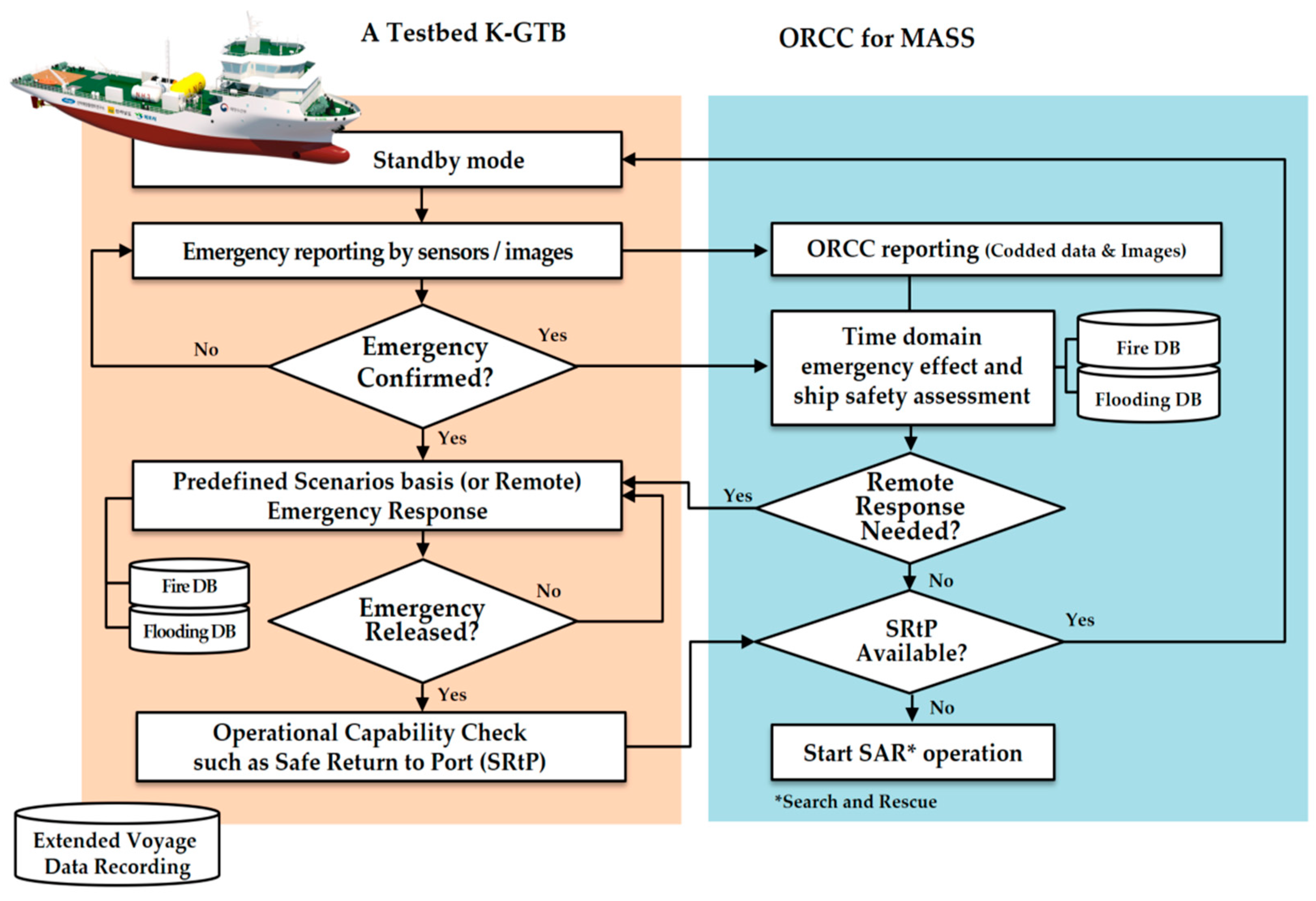
2.3. Remote Monitoring and Response to Emergencies
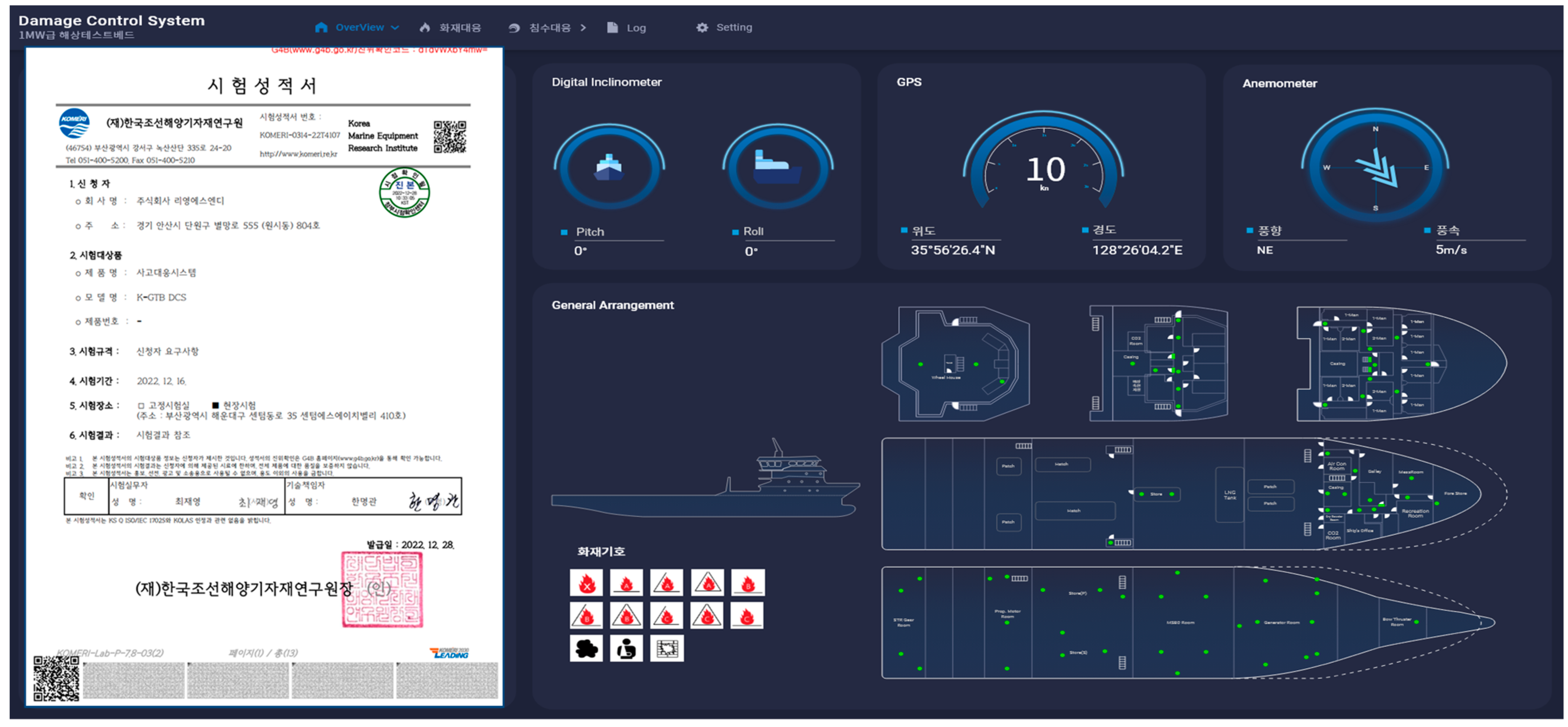
Ships sailing on the ocean use satellite communication to exchange data. However, the currently available commercial satellite services are quite expensive, costing around 35 US dollars per megabyte [15]. In addition to the communication load required for operating MASS, there is a significant technological and cost burden involved in exchanging high-quality, real-time video, images, and voice information for remote verification after an accident. For these reasons, this paper explores the concept of “coded shortcut keys” for rapid and intuitive accident response proposed by Kang et al. (2021) and considers the composition and utilization of a coded shortcut using graphical symbols from ISO 23120 [16] or IMO signs [17]. Table 3 explains the coded graphical symbols implementation concept.
This is an effort to simplify and make the process of accident response more intuitive by using coded graphical symbols. In emergency situations, MASS crew members or ORCC duty officers can effectively respond to the situation by following predefined emergency response procedures in an interactive manner using graphical symbol-based coded shortcut keys. Additionally, the coded graphical symbols can be useful in minimizing damage in MASS accidents by enabling quick situation sharing and simultaneous response efforts with minimal data communication requirements between MASS and ORCC.

3. Implementation

The concepts proposed in this paper, such as the floor-side placement of HVACs, may have limited practical application in actual ships without relevant regulations. However, based on simulations of flooding and fire scenarios, it is possible to develop an emergency response system for MASS in the form of a functionally extended alarm and monitoring system by utilizing the predefined accident scenario-based database and coded graphical symbol-based intuitive and simplified accident response procedures between MASS and ORCC. Although these concepts were originally proposed and developed by Kang et al. (2012) to improve the safety of conventional ships, the operation based on coded shortcut keys or accident response concepts based on predefined accident scenarios are more compatible with the characteristics of MASS [18].
The design alternatives and emergency response concepts for MASS discussed in this study are intended to be implemented on a demonstration ship (K-GTB) scheduled to launch in 2024. Figure 8 shows the conceptual diagram of the sensor network on the K-GTB, which can detect and control flooding accidents based on digital inclinometers, opening sensors, and flooding sensors. The control of watertight compartments is based on a presimulated flooding behavior analysis database. In the case of a fire accident, a combination of smoke sensors, heat sensors, gas detectors, and CCTV cameras are used to recognize and respond to the situation. The control of HVAC systems is also performed. Fire response activities are carried out using presimulated fire analysis databases, such as the propagation path of smoke and heat from the fire source and the control of HVACs and fire extinguishing systems. All these can be performed with minimal data exchange between MASS and ORCC by using coded graphical symbols from ISO 23120 or IMO signs. Figure 8 shows the concept for the sensor network and predefined accident scenario-based accident response system concept.
This study proposes a method of using a flood and fire database based on predefined accident scenarios to provide criteria for determining the occurrence of accidents along with signals collected from sensors. For instance, when a ship experiences heave, roll, or pitch movements beyond a certain level, the flood sensors recognize the ship’s accident situation and take measures such as closing watertight compartments and adjusting openings to prevent time-domain progressive flooding based on a similar flooding accident simulation database. The characteristics of vent installations, such as ceiling or floor-side installation, are also considered to effectively respond to accidents. In the case of fire accidents, a fire accident can be identified by multiple smoke and heat sensor signals and CCTV information. Then, HVAC control and fixed fire extinguishers for preventing fire spread can also be achieved by using a predefined fire scenario-based simulation database. The use of coded graphical symbols in this process helps MASS and ORCC effectively share and jointly respond to accident situations. Furthermore, it also assists in identifying the self-propulsion capability of the accident vessel and the presence of casualties for SAR (Search And Rescue) activities after accident response. Figure 9 shows the accident response procedure between MASS and ORCC, reflecting the proposed research concept. The safety procedures shown in Figure 9 take into account various scenarios related to the use of ammonia and methanol fuels, which are expected to become more prevalent due to ongoing decarbonization efforts, as well as accidents related to large-capacity marine batteries and fuel cells. These procedures can be further supplemented and refined based on risk assessment results, which can be used to develop accident response scenarios based on MASS route, cargo type, and propulsion method. Additionally, ORCC (Onboard Remote Control Center) can be used to remotely respond to accident situations or to incorporate automated response procedures.
Figure 10 shows the graphical user interface of the emergency response system for MASS reviewed in this study. It was designed in a form that can be applied to actual ships and demonstrates the operational concept based on the sensor network connectivity and coded shortcut keys. This prototype was confirmed to have achieved the intended performance through third-party verification in December 2022 and is scheduled to be installed on K-GTB in 2024 for the testing and demonstration of automated emergency response tasks.

4. Conclusions

In this paper, design alternatives and technological concepts were proposed to mitigate consequences during the operation of MASS. To prevent the spread of damage in the event of flooding or fire accidents, a technology that restricts airflow by placing HVACs on the floor side was suggested as a design alternative. Additionally, a technological concept was also proposed that assigns meanings to graphical symbols presented in ISO 23120 or IMO signs and encodes them, enabling the prompt sharing of situational information between MASS and ORCC with minimal data during the emergency response procedures. Despite practical constraints and implementation difficulties, the development of a prototype MASS accident response system based on predefined accident scenarios using a database and coded graphical symbols was achieved, and it obtained third-party verification. Considering safety concerns for transporting toxic cargo such as methanol and ammonia and a large number of passengers, the findings of this study are expected to contribute to mitigating the consequences of MASS operations in the event of accidents.

Author Contributions

Conceptualization, G.J.L. and H.J.K.; methodology, H.J.K.; software, G.J.L. and J.C.; validation, H.J.K. and J.C.; writing—original draft preparation, H.J.K.; writing—review and editing, H.J.K. and D.L. All authors have read and agreed to the published version of the manuscript.

Funding

This study was supported by a grant from the National R&D Project “Development of 1 MW class Marine Test-bed for Adoptability Demonstration of Alternative Fuels [1525012293/PMS5560]” funded by the Ministry of Oceans and Fisheries of Korea.

Institutional Review Board Statement

Not applicable.

Informed Consent Statement

Not applicable.

Data Availability Statement

Not applicable.

Acknowledgments

The authors would like to express their sincere gratitude for the support provided by the Ministry of Oceans and Fisheries, Republic of Korea, as well as the support of the Korea Autonomous Surface Ship Project Office (1525012448, PMS5673).

Conflicts of Interest

The authors declare no conflict of interest.

References

  1. IMO, MSC.1/Circ.1638. Outcome of the Regulatory Scoping Exercise for the Use of Maritime Autonomous Surface Ships (MASS). 2021. Available online: https://wwwcdn.imo.org/localresources/en/MediaCentre/PressBriefings/Documents/MSC.1-Circ.1638%20-%20Outcome%20Of%20The%20Regulatory%20Scoping%20ExerciseFor%20The%20Use%20Of%20Maritime%20Autonomous%20Surface%20Ships...%20(Secretariat).pdf (accessed on 11 April 2023).
  2. Wróbel, K.; Montewka, J.; Kujala, P. Towards the assessment of potential impact of unmanned vessels on maritime transportation safety. Reliab. Eng. Syst. Saf. 2017, 165, 155–169. [Google Scholar] [CrossRef]
  3. Suri, M.; Wróbel, K. Identifying factors affecting salvage rewards of crewless vessels—Lessons from a case study. WMU J. Marit. Aff. 2022, 21, 213–232. [Google Scholar] [CrossRef]
  4. Hoem, Å.S. The present and future of risk assessment of MASS: A literature review. In Proceedings of the 29th European Safety and Reliability Conference (ESREL), Hannover, Germany, 22–26 September 2019; pp. 22–26. Available online: https://www.researchgate.net/publication/338770018_The_present_and_future_of_risk_assessment_of_MASS_A_literature_review (accessed on 23 March 2023).
  5. Taguchi, K. Analysis on Collision Accidents and Maritime Autonomous Surface Ships. 2022. Available online: https://commons.wmu.se/cgi/viewcontent.cgi?article=3145&context=all_dissertations (accessed on 23 March 2023).
  6. Lee, E.-J.; Ruy, W.-S.; Seo, J. Application of reinforcement learning to fire suppression system of an autonomous ship in irregular waves. Int. J. Nav. Arch. Ocean Eng. 2020, 12, 910–917. [Google Scholar] [CrossRef]
  7. Mišković, D. MASS Level III–Exploration of Current Issues from an Operational Point of View. 2022. Available online: https://www.bib.irb.hr/1212655/download/1212655.Mikovi_2022-JMS_MASS_Level_3_Exploration_of_Current_issues_from.pdf (accessed on 23 March 2023).
  8. Ramos, M.A.; Utne, I.B.; Vinnem, J.E. Accounting for Human Failure in Autonomous Ship Operations; European Safety and Reliability Conference (ESREL): Trondheim, Norway, 2018; Available online: https://www.taylorfrancis.com/chapters/oa-edit/10.1201/9781351174664-45/accounting-human-failure-autonomous-ship-operations-ramos-utne-vinnem-mosleh (accessed on 23 March 2023).
  9. Martec, 2020. Cruise-DCS (Damage Control System). Available online: http://www.martec.it/?page_id=16 (accessed on 23 March 2023).
  10. Lee, D.; Kim, S.; Lee, K.; Shin, S.C.; Choi, J.; Park, B.J.; Kang, H.J. Performance-Based on-Board Damage Control System for Ships. Ocean. Eng. 2021, 223, 108636. Available online: https://www.sciencedirect.com/science/article/pii/S0029801821000718 (accessed on 23 March 2023). [CrossRef]
  11. Kang, H.J.; Choi, J.; Lee, D. Coded Shortcut Key Basis Rapid Plotting for Onboard Emergency Responses. Mar. Technol. Soc. J. 2021, 55, 73–87. Available online: https://www.ingentaconnect.com/content/mts/mtsj/2021/00000055/00000001/art00008 (accessed on 23 March 2023). [CrossRef]
  12. Lee, G.J.; Hong, J.-P.; Lee, K.K.; Kang, H.J. Application of Buoyancy Support System to Secure Residual Buoyancy of Damaged Ships. J. Mar. Sci. Eng. 2023, 11, 656. [Google Scholar] [CrossRef]
  13. Lee, G.J. Dynamic Orifice Flow Model and Compartment Models for Flooding Simulation of a Damaged Ship. Ocean Eng. 2015, 109, 635–653. Available online: https://www.sciencedirect.com/science/article/pii/S0029801815005314 (accessed on 23 March 2023). [CrossRef]
  14. Siu, N.; Woods, H.; Dey, M. NRC Fire Risk Research Plan: Fiscal Years 2001–2002. US Nuclear Regulatory Com-mission, Draft Report for Information, ADAMS ML003773018. Available online: https://nvlpubs.nist.gov/nistpubs/Legacy/TN/nbstechnicalnote1299.pdf (accessed on 23 March 2023).
  15. Northern Axcess Satellite Communication. Available online: https://www.northernaxcess.com/inmarsat-fleetbroadband-standard-rate-plan (accessed on 23 March 2023).
  16. ISO 23120:2022; Ships and Marine Technology—Graphical Symbols for Computer-Based Incident Response Systems. ISO: Geneva, Switzerland, 2022. Available online: https://www.iso.org/standard/74623.html (accessed on 30 December 2022).
  17. IMO. 2017. Escape Signs and Equipment Location Markings, IMO/A 30/Res.1116. Available online: https://wwwcdn.imo.org/localresources/en/KnowledgeCentre/IndexofIMOResolutions/AssemblyDocuments/A.1116(30).pdf (accessed on 30 December 2022).
  18. Kang, H.J.; Shin, J.-G.; Lee, J.K. A Business Model-Based Design of a Damage Control Support System for Naval Ships. Syst. Eng. 2012, 15, 14–27. Available online: https://incose.onlinelibrary.wiley.com/doi/pdf/10.1002/sys.20191 (accessed on 30 December 2022). [CrossRef]
Figure 1. Emergency response procedures analysis result for conventional ships and MASS degree three and four ships.
Jmse 11 00907 g001
Figure 2. The ship model and specifications for flooding simulations.
Jmse 11 00907 g002
Figure 3. Analysis results of flooding charateristics of flooding scenario 1.
Jmse 11 00907 g003
Figure 4. Analysis results of flooding charateristics of flooding scenario 2.
Jmse 11 00907 g004
Figure 5. Stability diagram of a heeled Ship: center of gravity (G), center of buoyancy (B), righting lever (GZ), and metacenter (M).
Jmse 11 00907 g005
Figure 6. Analysis results of fire simulation: (a,b) ceiling side vents (scenario 1); (c,d) floor side vents (scenario 2).
Jmse 11 00907 g006
Figure 7. Construction result of ship model(K-GTB) (a), FDS-based fire simulation examples (b) and an evacuation analysis example (c).
Jmse 11 00907 g007
Figure 8. Sensor-network-based accidents response concept for MASS using K-GTB.
Jmse 11 00907 g008
Figure 9. An example of an emergency response process between MASS and ORCC.
Jmse 11 00907 g009
Figure 10. An example of the graphic user interface of our accidents response system for MASS and certification of third-party verification. The non-English document on the right shows a third-party verification certificate from KOMERI (Korea Marine Equipment Research Institute).
Jmse 11 00907 g010
Table 1. Specifications of the example ship for flooding characteristic comparison.
Research TopicKey FindingsReferences
The assessment of potential impact of unmanned vessels on maritime transportation safetyIntroducing unmanned ships in the maritime industry poses safety challenges that require early stage safety measures and procedures, and further research is needed to understand their safety implications.Wróbel, K. et al., 2017 [2]
Identifying factors affecting salvage rewards of crewless vessels—lessons from a case studySalvaging crewless ships is complex, with a need for balance between interests and potential environmental risks. It is difficult to develop a standardized formula due to the lack of standards and history of discretion.Suri, M. et al., 2022 [3]
The present and future of risk assessment of MASS: a literature reviewReviewed the current state of the art of risk assessment of maritime autonomous surface ships (MASS) and identified gaps in the literature.Hoem, Å.S., et al., 2019 [4]
Analysis on collision accidents and maritime autonomous surface shipsAnalyzed collision accidents involving MASS and identified factors that contributed to the accidents, such as malfunctioning sensors and lack of human intervention.Taguchi, K. et al., 2022 [5]
Reinforcement learning to fire suppression system of an autonomous shipA fire suppression solution for an autonomous ship. The model successfully reached the fire source despite the sea state and location, but the authors did not consider operation time delay.Lee, E. et al., 2020 [6]
MASS Level III—exploration of current issues from an operational point of viewExplored operational issues related to MASS, such as communication, decision making, and cyber security, and proposed solutions to address these issues.Mišković, D. et al., 2022 [7]
Table 2. Flooding simulation scenarios.
Scenario 1Scenario 2
2nd Deck VentHigh (Ceiling)Low (Floor)
3rd Deck VentHigh (Ceiling)Low (Floor)
Bottom Deck VentHigh (Ceiling)High (Ceiling)
All doors are open.
Table 3. The concept of sharing accident and response information using coded graphical symbols. The applied fire symbols may differ from the content of actual IMO signs and ISO standards due to copyright issues.
A Class Fire IdentifiedA Class Fire-Fighting in ProgressA Class Fire-Fighting Completed
SymbologyJmse 11 00907 i001Jmse 11 00907 i002Jmse 11 00907 i003
ActionClick(ORCC)/Automatic input(MASS) the class A fire buttonClick(ORCC)/Automatic input(MASS) the class A fire button once moreClick(ORCC)/Automatic input(MASS) the Class A fire Button once more
Code000001001001100001
Meaningmultiple sensor signal identifiedfire-fighting system activatedfire-fighting completion confirmed
Disclaimer/Publisher’s Note: The statements, opinions and data contained in all publications are solely those of the individual author(s) and contributor(s) and not of MDPI and/or the editor(s). MDPI and/or the editor(s) disclaim responsibility for any injury to people or property resulting from any ideas, methods, instructions or products referred to in the content.

