Abstract
The commingling of the two types of heavy fuel oils (fuel remaining in the tanks and fuel loaded) is determined by the company’s guidance and safety management system. Remained heavy fuel oil must be distributed in the heavy fuel oil tanks before bunkering efficiently, in order to obtain maximum bunker loading. This paper proposes the use of the bisection method to calculate the distribution of the remaining fuel in heavy fuel oil tanks on the liquefied natural gas carrier. The use of this method is illustrated by three examples. The first and second examples show that the iterations converge quickly to the solution. It is found that maximum tank filling with fuel commingling is achievable if the bunker intervals satisfy the company policy of 10% as a lower limit of tank filling, and 90% to 100% as an upper limit. The third example illustrates a situation when the proposed mathematical model does not allow maximization of the total tank capacity without risk assessment. The mathematical spectrum of the possible tank filling solution is presented. Despite its limitations, the bisection method is suitable for onboard applications because it is simple and fast, and can be easily programmed.
1. Introduction
Exposure to air pollutants has harmful effects on human health, as was recognised as early as the time of Hippocrates, ca. 400 BC. Efforts to reduce it intensified in the 1950s and 1960s, as a result of the negative consequences of substantial air quality degradation [1]. Heavy fuel oils are made of raw crude oil and composed of high-molecular-weight paraffinic and aromatic hydrocarbons, along with minor amounts of metals and sulphur, with boiling points greater than 350 °C and high viscosity. Fuel emissions decreased through the addition of lower-viscosity residuals and distillates, but additional heating and onboard processing (filtration and separation) are required to achieve suitable flow and combustion performances for engine use [2,3]. Globally, the most important measure was a stepwise reduction in the sulphur content in marine fuel, implemented by the International Maritime Organisation (IMO). Under the revised International Convention for the Prevention of Pollution from Ships (MARPOL) Annex VI, a global sulphur cap of 0.5% m/m has been effective since 1 January 2020 [4,5], to control and reduce emissions of air pollutants (nitrogen oxides, particulate matter, sulphur oxides, and volatile organic compounds) [6]. Within specific designated emission control areas (SECAs), the sulphur content in fuel has been limited to 0.1% by mass since 2015.
Today, about 60% of all vessels are powered by engines that use heavy fuel oil [7,8,9], and are the source of a considerable share of SO2 emissions, especially in port cities, substantially contributing to air quality degradation [10]. For compliance with the 2020 sulphur regulation, three main options are available to ship owners: use very-low-sulphur fuel oil (VLSFO), distillate marine (DM) or residual marine (RM) fuel oils with sulphur content lower than that required; switch to alternative, sulphur-free fuels, such as biodiesel, LNG, methanol, ammonia, or hydrogen; and the use of exhaust gas cleaning systems (scrubbers) [11]. Because the use of alternative marine fuels (carbon-neutral fuels) also helps to reduce greenhouse gas emissions, it can be expected that it will increase [12,13,14]. However, substantial efforts are needed to solve issues related to the production capacity and affordability of carbon-neutral fuels, and fossil fuels may remain the main type of fuel used in the near future [15]. For example, in 2018, the shares of LNG and methanol were 3%, and of biofuels, less than 1% [16].
As a result of the demand for RM VLSFOs, a share of composite fuels (blends of residual and distillate components) has increased, leading to greater variations in the composition and formulations, and increased attention to fuel management practices [17]. Namely, new types of blended fuels have been produced with shifted attention from viscosity and density control to sulphur content, and as a result, the characteristics of RM changed. In comparison with RM high-sulphur fuel oil (HSFO), RM VLSFOs generally have lower viscosity, lower density, lower Micro Carbon Residue value, lower Calculated Carbon Aromaticity Index, higher net specific energy, higher pour point, and wider viscosity distribution [18]. An important property of RM fuel oils is stability (resistance to precipitate asphaltenic sludge), influenced by fuel formulation, thermal and mechanical stresses, and storage time. Formed sludge causes numerous problems, including filtration and separator problems. Because stability depends on interactions between asphaltenes and other components of the complex chemical matrix (paraffins, naphthenes, aromatics, and resins), the risk of asphaltene precipitation in VLSFOs is increased in comparison to in HSFOs [19]. The responsibility of the supplier is to supply stable fuel, as specified in ISO 8217:2017. However, two stable fuels may be incompatible at some of, or over the entire, mixing ratio, and the engineers on board must take care to avoid incompatibility issues [19].
The safest way to avoid fuel compatibility issues is to segregate different bunker stems whenever possible. Therefore, most branded gasoline firms require that their product is not commingled, to preserve the integrity of the brand. The commingling of the fuel is defined according to [20] as the term which generally applies to the mixing of two petroleum products with similar specifications.
However, in practice, commingling is very often unavoidable. Each company has its voyage plan concerning safe fuel oil margin. The safe fuel oil margin is related to the distances between two bunker loading positions. If the charterer decides that cargo must be delivered from the loading port to the delivery port without stoppage, then the charterer requests to top up tanks with heavy fuel oil (HFO). However, the charterer may request that the ship stops on the way back from the discharging port and take the HFO if the price for that bunker is more favourable for the charterer. In such cases, a certain quantity of the old HFO remains inside the tanks, and it must be distributed in order to avoid commingling with the new HFO that needs to be loaded. Because the compatibility report for the old fuel and new fuel is often not available before commencing the bunkering, the vessel must load the HFO bunker blindly. It is not unusual that even the charterer delays or avoids giving information about fuel quality, but gives only a frame for the fuel stem, which increases the negative impact of the two different HFOs on the vessel filtration and purification system. Although the ship is provided with the fuel compatibility test kit, once the bunker tanker is alongside the LNG carrier, it is too late to cancel the operation. The vessel owner reluctantly approaches the charterer to change the HFO bunker type, as that will be a costly operation that will have a bad impact on the ship owner from the charterer’s point of view.
For cases when commingling is necessary, the ship owner’s safety management system (SMS) policy allows mixing a maximum of 10% of one fuel with the other one at the chief engineer’s discretion [21]. Additionally, the total quantity of oil after the bunkering should be maximal (all tanks should be filled to capacity). The problem is how to redistribute old fuel inside various tanks before loading new fuel to maximize total loading quantity while following SMS policy request. Currently, to the best of our knowledge, there is no proposed method to solve this problem. Therefore, chief engineers use various ways to determine a distribution plan. There is a possibility that they spend a lot of time and that some solutions are not optimal. In this manuscript, the bisection method is proposed as a solution for the multi-fuel oil bunker tank filling problem. In order to illustrate the mathematical model, the vessel Al Utouriya, with her tank distribution, is taken as the example [22].
2. Description of the Heavy Fuel Oil Tanks and Their Application
The Al Utouriya is a Q-flex LNG carrier with a reliq plant. The whole quantity of the boiled-off gas reliquefies back to the cargo tanks. In the case of a higher presence of N2 inside the tanks, that gas is burned in the gas combustion unit along with the LNG traces, to prevent releasing the LNG into the atmosphere. The burning of the N2 together with the traces of LNG is additionally required, as the liquefaction point of the N2 is lower than that of LNG, and in that sense, captured N2 circulating in the reliq system only degrades the efficiency of liquefaction. As that type of LNG carrier liquefies all of the cargo and does not use boil-off gas for the machinery, the main sources of the chemical energy in the combustion process inside the engine are HFO and DM. The HFO is permanently used while sailing, and DM is used only in special areas, where the use of 0.5% S of HFO is forbidden.
There are certain restrictions, according to the company SMS policy, that are related to the filling volume of the tanks. Forward HFO bunker tanks are allowed to be filled up to 85%, while all other tanks may be filled up to 90%. The HFO tank total capacities, in m3, among the nine tanks of the observed vessel, are shown in Table 1.

Table 1.
Total HFO bunker capacity in cubic meters.
In general, the bunker tanker pumping capacities vary from 150 to 3500 m3/h [23]. The bunker stem is given in MT, and the bunker barge calculates the pumping rate in metric tons per hour (MT/h). If the HFO density is taken to be 970 kg/m3, then the filling capacity in MT is given in Table 2.

Table 2.
Total HFO bunker capacity in metric tons, if the density is 970 kg/m3.
In Table 1 and Table 2, all HFO tanks are storage tanks, with the exception of the port and starboard HFO service tanks, and port and starboard HFO settling tanks. Service tanks feed purified fuel from the settling tanks to the main propulsion units on the port and starboard sides, and to auxiliary generators for electrical power production.
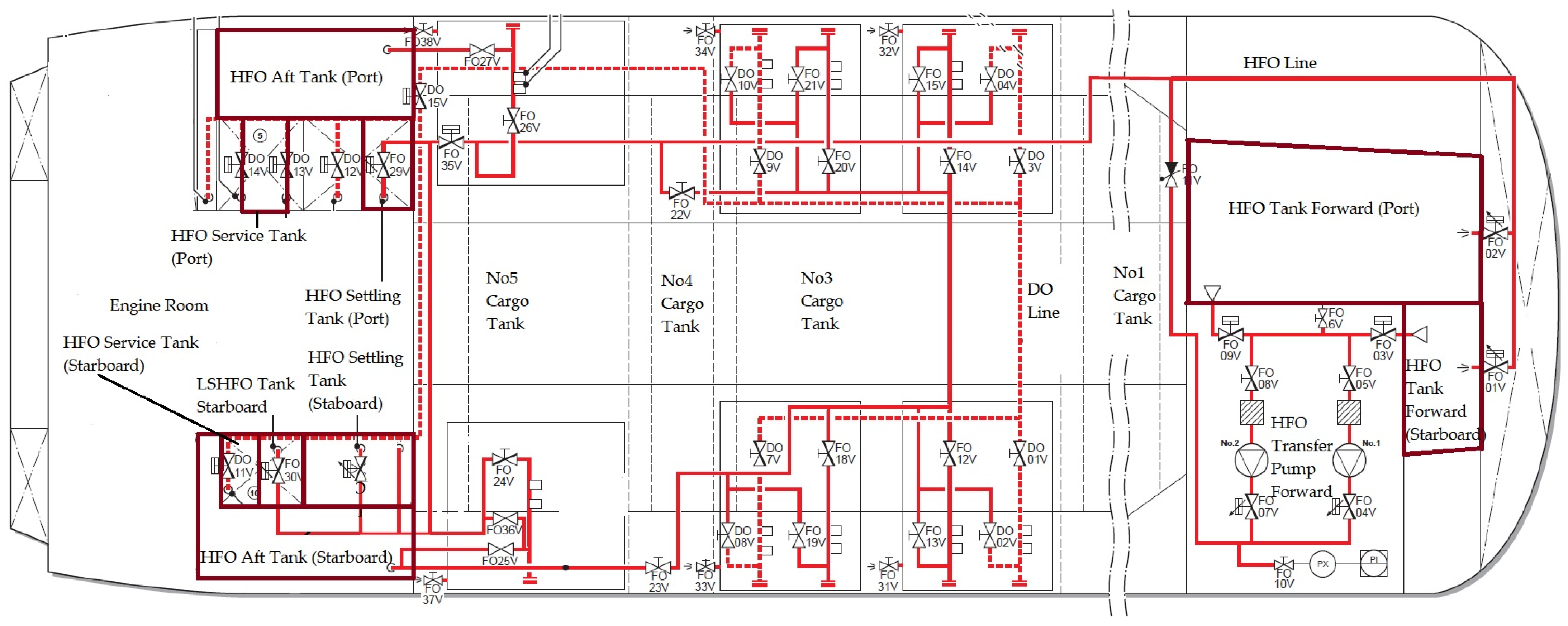
The distribution and general arrangement of the HFO bunker tanks are given in Figure 1 and Figure 2, respectively.
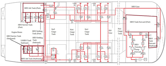
Figure 1.
HFO bunker distribution on the LNG carrier.

Figure 2.
The general arrangement of HFO bunker tank locations on the LNG carrier.
The procedures of distributing old fuel and subsequently loading new fuel are affected by the necessity of ballasting or deballasting operations. Depending on the location of bunkered fuel, it is required to carry out the ballasting or deballasting operation when the fuel is taken or laden from one side of the vessel, as in HFO Aft tanks port and starboard and low-sulphur fuel oil (LSHFO) tank starboard. The same ballasting or deballasting operation occurs when the bunker is filled or taken from the forward port and starboard tanks to keep the ship’s trim and list in the neutral position. As this LNG carrier calls various ports in the world, some discharging ports have no required seawater depth for this type of LNG carrier and, in that case, the quantity of fuel must satisfy restrictions concerning under keel clearance, which is often different from the local port authorities’, and ship owners’, SMS policies. Therefore, the maximum loading capacity may be lower than the one shown in Table 2.
3. Mathematical Model of HFO Bunker Distribution and Maximal Loading Quantities inside the HFO Tanks
Several factors must be considered in order to plan the optimal quantity of HFO fuel inside tanks. As mentioned previously, forward bunker tanks are not allowed to be filled up to more than 85%, while aft tanks may be filled up to 90% by SMS policy. Therefore, those allowed quantities will be considered as 100%. Furthermore, loading of the new fuel is allowed if 10% of the tank is filled by the old HFO fuel (in which case, 90% of the new HFO fuel is allowed) or if 90% of the tank is filled by the old HFO fuel (in which case, 10% of the new HFO fuel is allowed) to fulfil the rule concerning commingling. In order for the vessel to maintain stable plant operation, HFO service tanks (enumerated as No8 and No9 in Table 2) should be filled up to 90% before the bunker operation, in order to avoid a blackout scenario during the bunkering of the ship. Therefore, they will be excluded from consideration. With such limitations, the number of disposable tanks is reduced from nine to seven HFO tanks. Thus, the number of possible combinations for distributing the fuel equals 27, or 128 possible combinations, which vary from empty to partially filled tanks before bunker operations.
3.1. Mathematical Explanation of the Given Problem
An ordinary bisection method for iteratively converging on a solution that is known to be inside the interval [a, b] proceeds by evaluating the function in question at the midpoint of the original interval of a and b [24,25]
and it may be tested to see which of the subintervals is a solution.
The method is then repeated with the new interval as much as possible to find the solution with the desired accuracy. If an and bn are the endpoints at the nth iteration (with a1 a and b1 b) and rn is the nth approximate solution, then the number of iterations required to achieve an error smaller than ε is found by
and thus, rn is defined by
In order for the error to be smaller than ε,
After taking the natural logarithm of both sides, an obtained solution for n is
3.2. Mathematical Binary Setup and Filling Limits
The permutations of seven HFO tanks may be listed as 1, which means that the tank is filled up partially or fully, or 0, which means that the tank is empty. The possible combinations are listed in Table 3.

Table 3.
Binary permutation distribution of the HFO tanks.
Table 4 shows the allowed quantities (intervals) of the old HFO fuel in the tanks before loading the new HFO.

Table 4.
The lower and upper filling intervals of the HFO tanks.
3.3. Examples of the Fuel Distribution by Using the Bisection Method
The given intervals may be determined and then maximized by the bisection method, which is the division of a given curve, figure, or interval into two equal parts (halves) [24]. The use of the bisection method in cases when a mathematical solution can be directly applied in practice is illustrated by the following two examples.
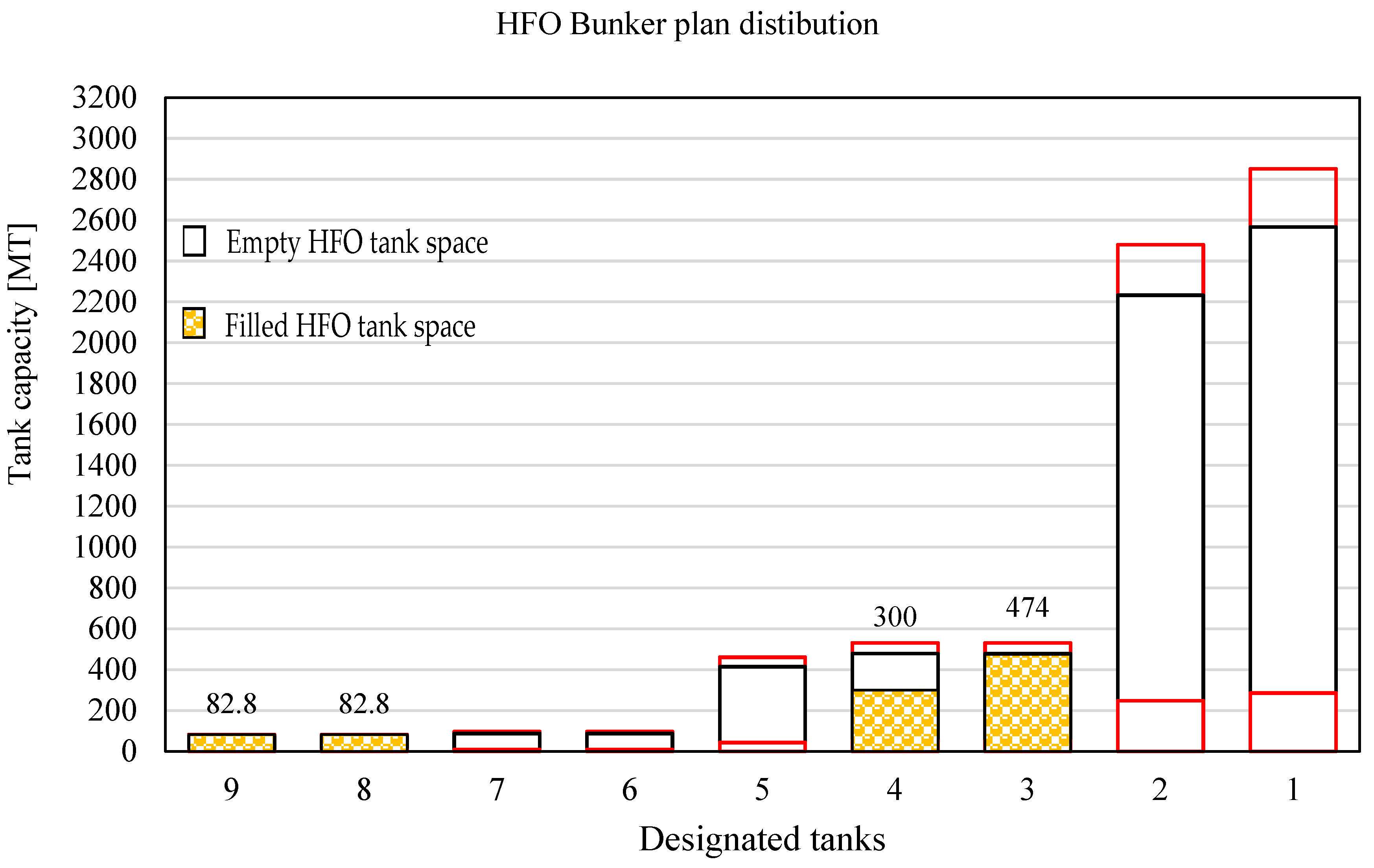
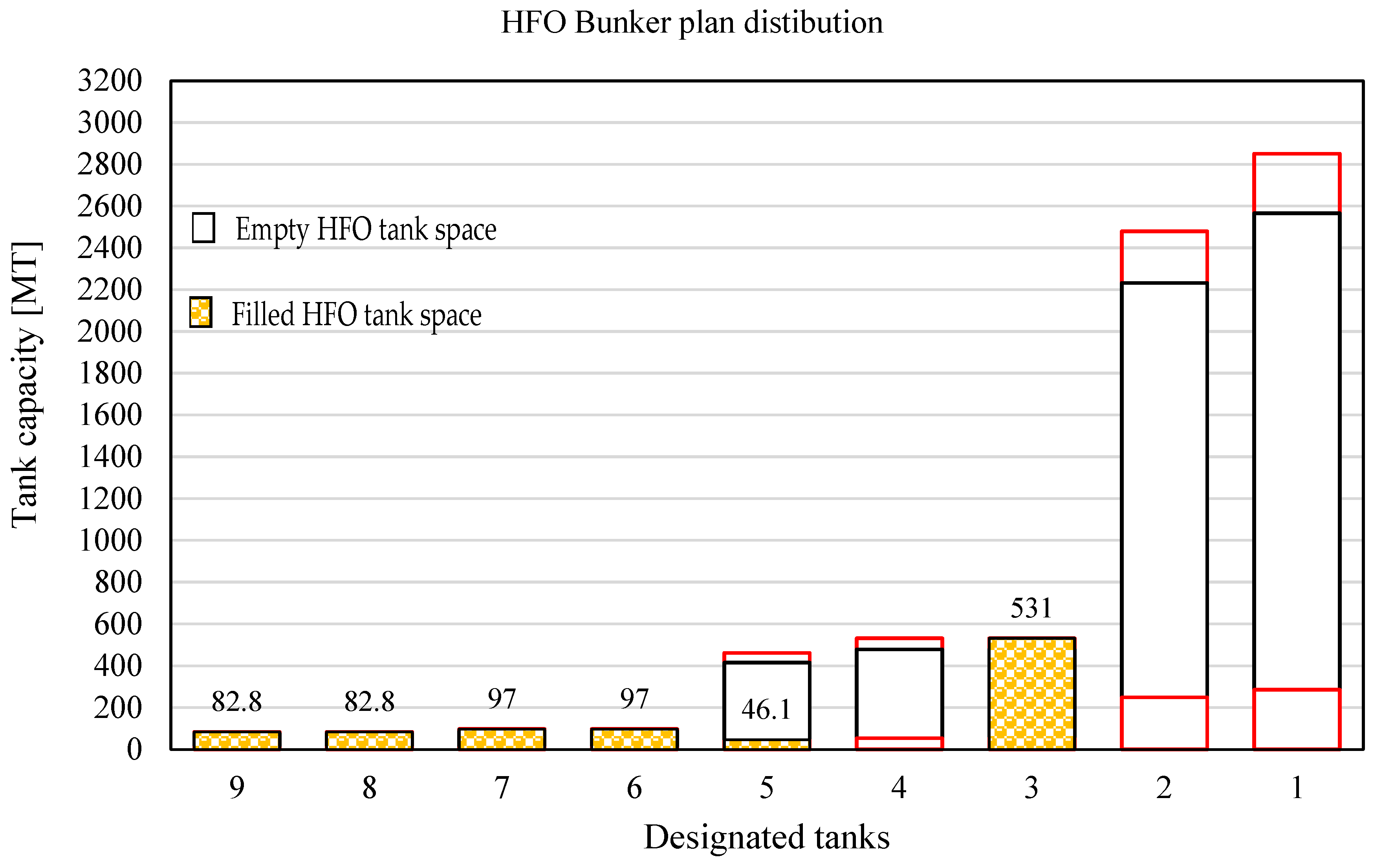
The first example is to distribute 939.6 MT of the old HFO fuel. In total, 165.6 MT is located in the service tanks. The remaining fuel is inside tanks No3 (474 MT) and No4 (300 MT) which is 774 MT in total (Figure 3). The red lines in Figure 3 are lower and upper intervals, i.e., from 0 to 10% and 90 to 100% of the tank filling limits. Such a configuration of tanks matches permutation 24. In the first iteration, the old HFO may be loaded in the aft starboard tank, forward starboard tank, aft port tank, LSHFO tank starboard, and the settling port tank in the interval from 477.9 to 897.6 (248 + 531 + 53.1 + 46.1 + 9.7 + 9.7) MT. The result of the first iteration is 687.8 MT, that of the second iteration is 582.8 MT, and that of the third iteration is 530.4 MT, which matches with the almost-full HFO starboard or port tank. In this case, the choice will be the aft port tank (No3) with 530.4 MT. The remaining quantity is 243.6 MT, which is simply distributed as follows: 97 MT to the settling tank port, 97 MT to the settling tank starboard, and 49.6 MT to the aft starboard tank (Figure 4). With such a configuration, the total bunker capacity of the new and old fuel is maximized to 7213 MT, which is the maximum capacity, and the new bunker loading quantity is 6273.4 MT.
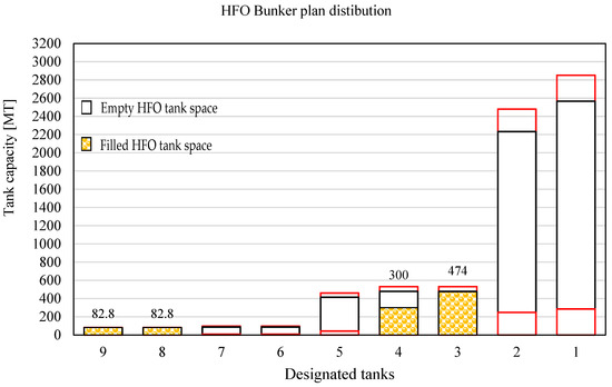
Figure 3.
HFO bunker condition before bunker distribution for the first example.
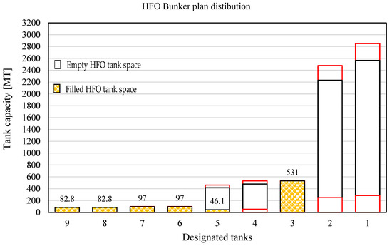
Figure 4.
HFO bunker condition before bunker loading for the first example.
Such a transfer combination must be planned if there is no provided additional transfer pump in the engine room which handles fuel transfer from the aft to forward tank.
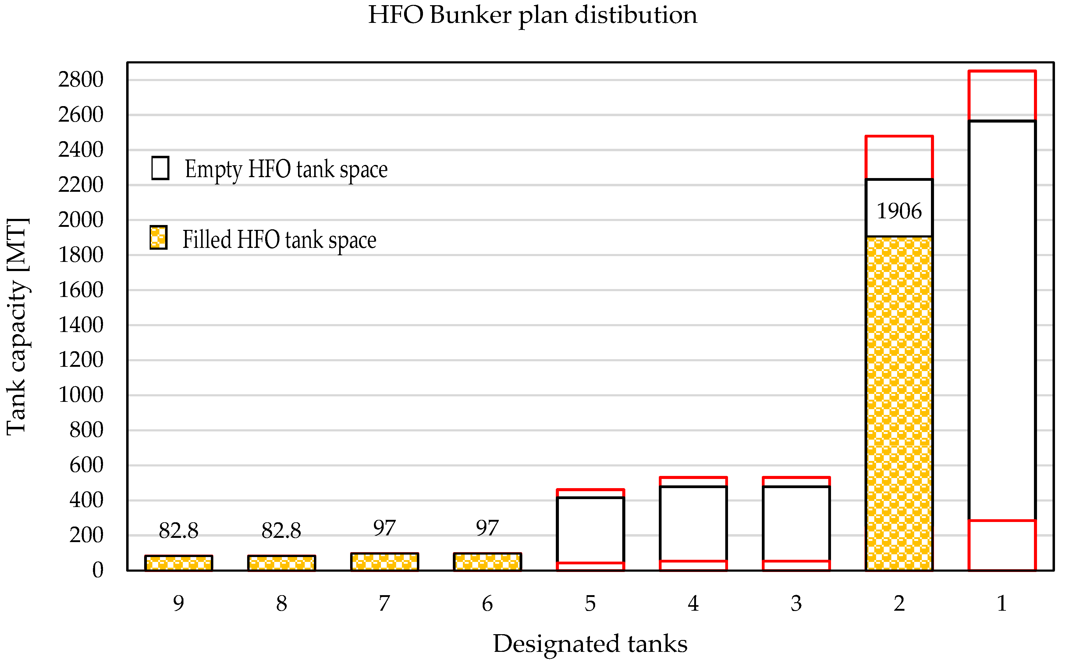
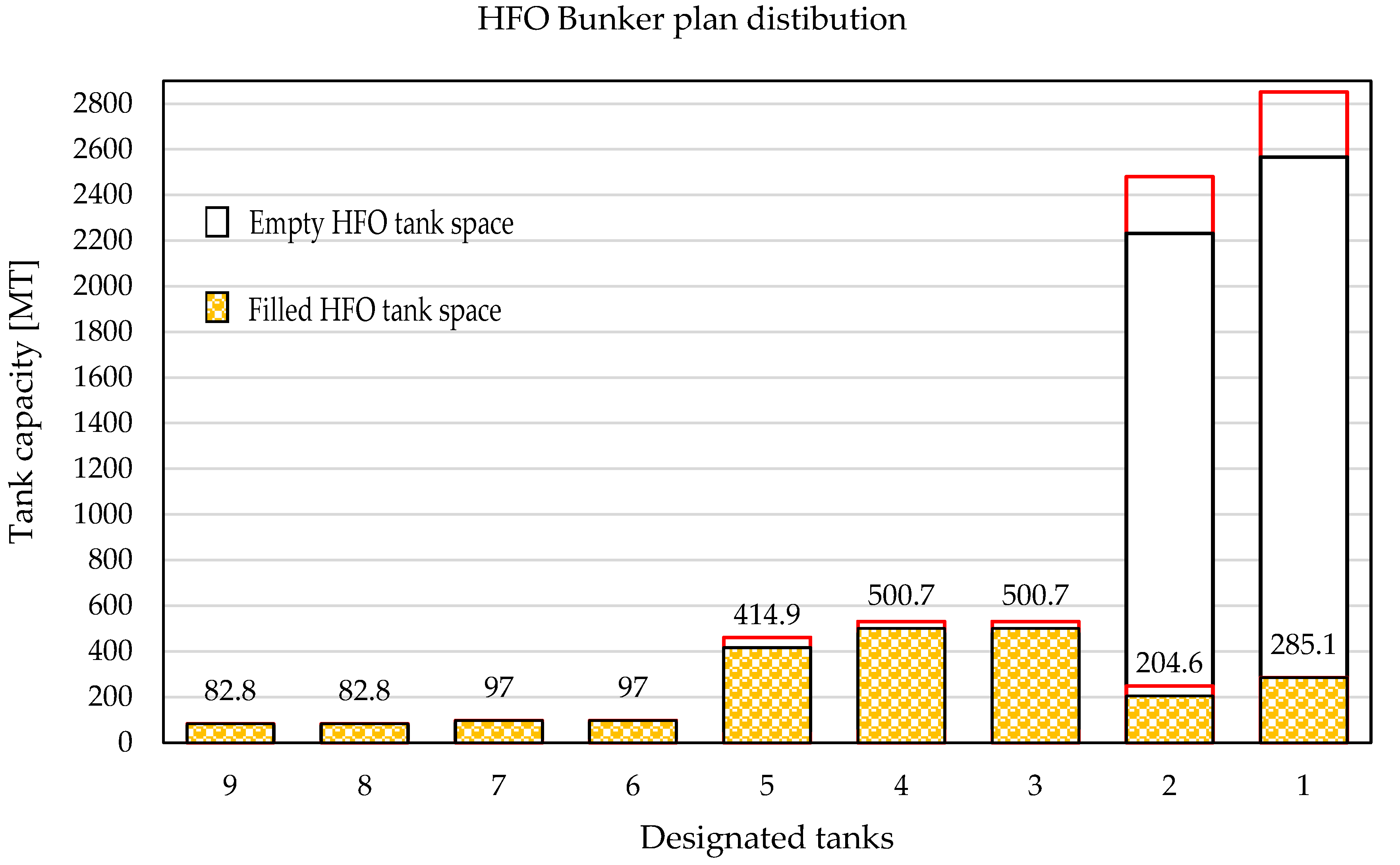
The second example is to distribute 2265.6 MT of the old HFO. In total, 165.6 MT is located in the service tanks. The remaining fuel is located in tank No2 (1906 MT) and in the two settling tanks on the port (97 MT) and starboard (97 MT) sides (Figure 5). Such a configuration matches permutation 36. The filling interval is set from 533.1 (10% in forward tanks port and starboard) to 2009.9 (10% in forward tanks port and starboard and full tanks aft port and aft starboard, and 90% LSHFO tank). The first iteration supplies 1271.5 MT, which cannot be loaded, as the start of the interval is higher than the full capacity of the available tank aft port or starboard. In that case, the interval moves to subinterval 285.1–2009.9 MT. The first iteration of the new interval is 1147.5 MT, the second iteration is 716.3 MT, and the third iteration is 500.7 MT, which is in the desired interval from 90 to 100% of the aft port or aft starboard tank capacity. With such a solution, the old fuel from tank No2 is distributed as follows: 500.7 MT in aft port, 500.7 MT in aft starboard, 414.9 in LSHFO, 285.1 in forward port, and the remaining old fuel (204.6 MT) is in the forward starboard tank, which is 8.25% of the tank capacity and complies with the company policy (Figure 6). With the second configuration, the total bunker capacity of the new and old fuel is 7213 MT, which is the maximum capacity, and the bunker loading quantity is 4947.4 MT.
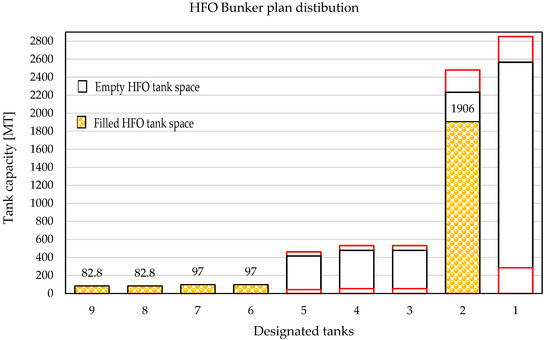
Figure 5.
HFO bunker condition before bunker distribution for the second example.
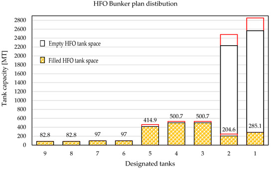
Figure 6.
HFO bunker condition before bunker loading for the second example.
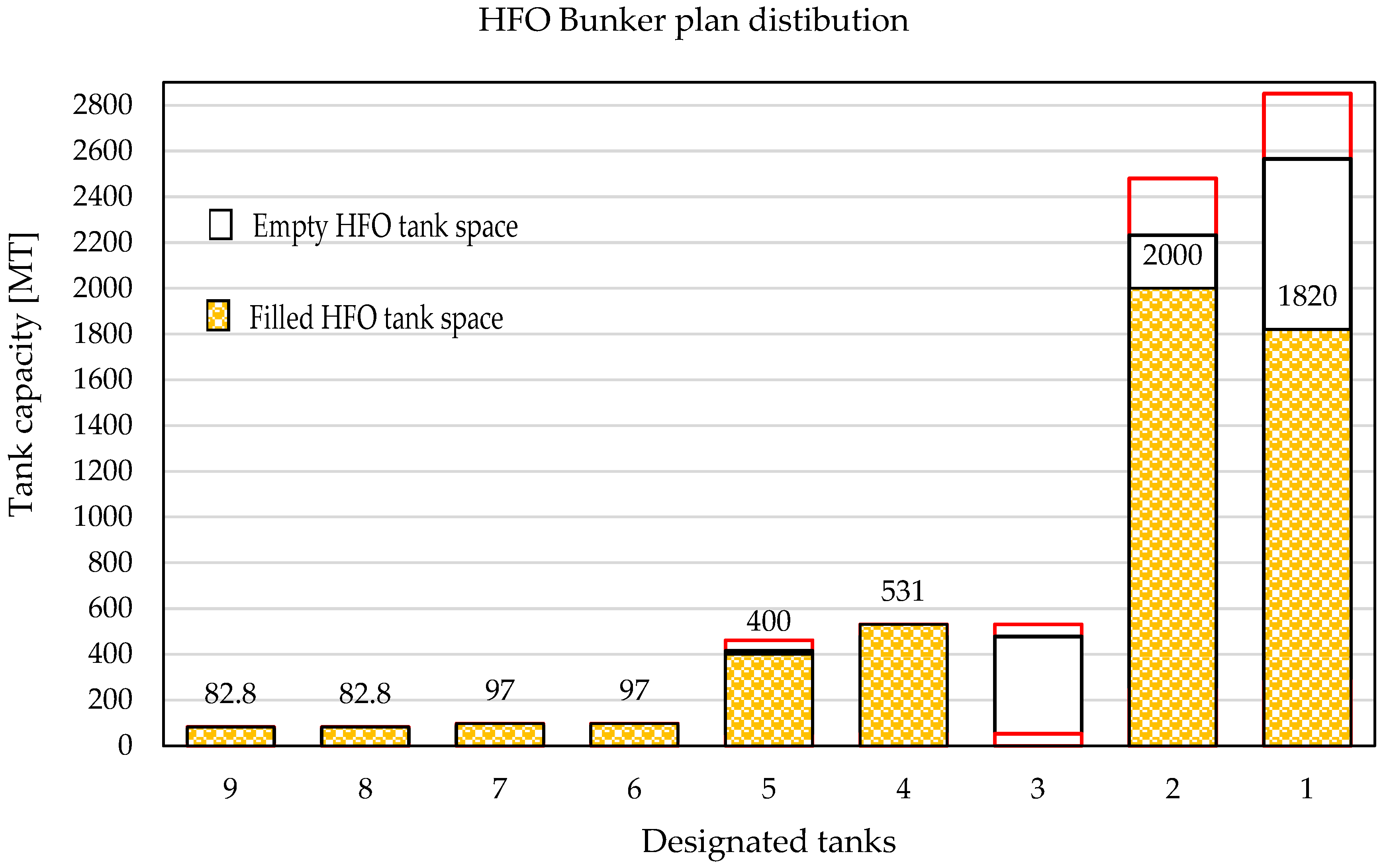
The third example illustrates a situation when the proposed mathematical model does not allow for maximization of the total quantities, because the calculated old fuel quantity is in the interval between 10% and 90% of tank capacity. In this case, the quantity of the old fuel is 5110.6 MT, located as follows: the service tanks contain 82.8 MT, both settling tanks full (97 MT), LHSFO 400 MT, HFO aft port 531 MT, HFO aft starboard 0 MT, forward starboard 2000 MT, and forward port 1820 MT (Figure 7). The total capacity of the bunker is 7213 MT.
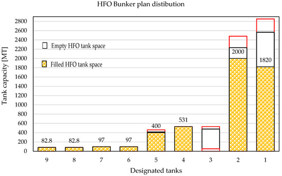
Figure 7.
HFO bunker condition before bunker distribution for the third example.
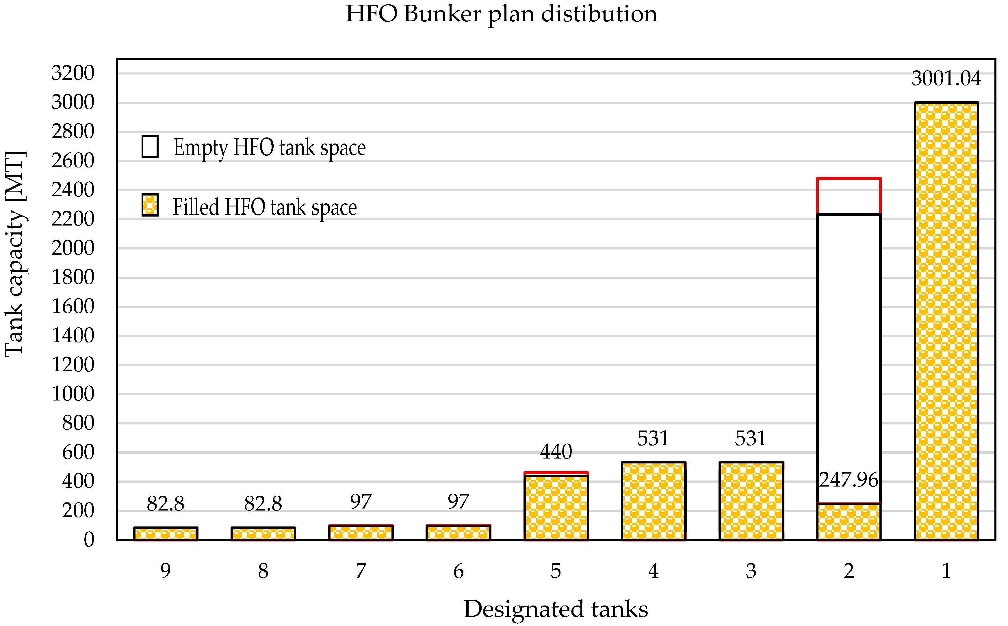
The maximum quantity, in this case, cannot be achieved because, for the given interval from 53.1 to 5861.4 MT, the bisection iteration solution is 2957.25 MT, which is out of range for the forward port tank. Taking into account the 43.79 MT that cannot be transferred by respecting all requirements, the iteration solution is corrected to 3001.04 MT. In this case, the problem may be solved if 1181.04 MT of the fuel is transferred from the forward starboard tank to the forward port tank. However, in that case, the tank is filled to 89.47%, which is more than allowed by SMS policy. In such a case, it is required to prepare risk assessments and send them for approval to the company. In the risk assessment, it will be required to assess aspects of the voyage, weather conditions, the fuel quality, and the heating temperature of the stored HFO in the forward tank, in order to avoid overflowing of the HFO onto the deck through the bunker tank vent pipe. An additional 818.96 MT from the forward starboard tank must be distributed because 10% of the capacity is 247.96 MT. Additionally, 531 MT may be transferred to the aft port tank, and the remaining 40 MT is transferred to the LSHFO tank (Figure 8). With such a configuration, the forward starboard tank may be bunkered to 2231.6 MT, which maximizes fuel to 7342.2 MT, which can then be approved by the company although it is more than allowed by SMS policy.
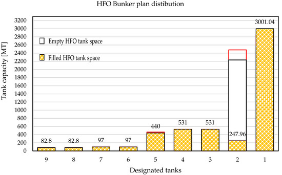
Figure 8.
HFO bunker condition before bunker loading for the third example.
3.4. Mathematical Spectrum of Solution Intervals
As fuel remains in more tanks, or they are partially filled, the number of combinations decreases, and maximized filling quantity is reduced. The mathematical spectrum of solution intervals, in cases when one tank is kept fixed and the rest (from six to one) are varied, is presented in Table 5. The fixed tank is filled up to 10%, while the other tanks are filled in the range from 90 to 100%.

Table 5.
The interval of the tanks and tank available spaces.
The problem becomes even more complicated if three different HFO fuels remain in the vessel at the same time. Such a situation occurs when problematic fuel is loaded and this fuel cannot be used in auxiliary diesel generators to avoid a possible blackout situation. Instead, it is used in the main engines, which causes excessive wear of the piston ring, cylinder liner, and fuel distribution system of the main engine. In the worst-case scenario, metal dust may cause excessive wear of the piston rod. In that case, problematic fuel must be kept separated, which additionally complicates loading distribution.
Using the bisection method, it is easy to find the optimum total bunker filling because it may be programmed by one of the methods described in [26,27].
4. Conclusions
The bunkering operation should be planned carefully in order to avoid human error. All filling restrictions, and the human factor, should be considered. In cases when the maximization of the filling level is in question, the risk of HFO bunker pollution is increased, and the crew must operate carefully. The bunker tanker pumping capacities vary from 150 to 3500 m3/h. With high pumping capacities, the crew must respond quickly, which increases the possibility of errors. However, a reduced pumping rate prolongs bunker operation to more than 24 h, which also increases the probability of errors. Therefore, it is essential to coordinate with the bunker tanker properly, reduce the pumping rate when topping up of the tank is approaching, and enable the crew to rest before bunker operation. The smallest tanks should be filled first, and the largest tanks last, because crew focus weakens over time, and the time for reaction is longer for the larger tanks. Additionally, the bunkering operation should be planned to fill as few tanks as possible at the same time.
To the best of our knowledge, the bisection method is applied here for the first time to HFO bunker distribution, with commingling and filling restrictions for the given examples on a ship with nine tanks.
Generally, the problem is solved quickly by a bisection method if the solution is in between the lower and upper intervals. The iterations converge quickly to the solution. The bisection method targets the tank in intervals of either 10, 90, or 100%. If one tank is targeted, all tanks are also within the desired interval.
Aside from solutions that may be used immediately, there is a mathematical spectrum of solutions that are obtained by correcting an iteration solution. Some of them may be used after risk assessment. In some cases, HFO locations among tanks do not allow for obtaining optimum solutions. In these cases, it will be required to bunker less than the maximum quantity.
Other numerical methods, such as regula falsi, may also be used to solve this problem. However, they are not practical for use on board because they require a high level of mathematical knowledge and programming skills. The use of the bisection method is proposed because it is simple, fast, and can be easily programmed by a crew member. Therefore, there are no additional costs for the ship owner.
In this study, the temperature correction and pressure correction factors are not considered. The mathematical model will be extended to include them in future work. Additionally, the effect of the proposed method on stability will be investigated, and cost analysis will be completed.
Author Contributions
Conceptualization, I.P. and V.M.; methodology, V.M.; software, M.K.; validation, I.P., M.K. and J.Č.; formal analysis, I.P.; investigation, I.P.; resources, I.P.; data curation, I.P.; writing—original draft preparation, V.M. and J.Č.; writing—review and editing, I.P. and M.K. All authors have read and agreed to the published version of the manuscript.
Funding
This research was supported by the Croatian Science Foundation, under the project IP-2018-01-3739, and University of Rijeka scientific grant uniri-tehnic-18-18-1146.
Data Availability Statement
Available on request.
Conflicts of Interest
The authors declare no conflict of interest.
Abbreviations
| DM | Distillate Marine Fuel Oil |
| HFO | Heavy Fuel Oil |
| HSFO | High-Sulphur Fuel Oil |
| IMO | International Maritime Organisation |
| LNG | Liquefied Natural Gas |
| LSHFO | Low-Sulphur Fuel Oil |
| MARPOL | International Convention for the Prevention of Pollution from Ships |
| RM | Residual Marine Fuel Oil |
| SECAs | Sulphur Emission Control Area |
| VLSFO | Very-Low-Sulphur Fuel Oil |
References
- Fowler, D.; Brimblecombe, P.; Burrows, J.; Heal, M.R.; Grennfelt, P.; Stevenson, D.S.; Jowett, A.; Nemitz, E.; Coyle, M.; Liu, X.; et al. A Chronology of Global Air Quality. Phil. Trans. R. Soc. A 2020, 378, 20190314. [Google Scholar] [CrossRef] [PubMed]
- Notes of Heavy Fuel Oil by the American Bureau of Shipping, ABS Plaza, 16855 Northchase Drive, Houston, TX 77060 USA. 2001. Available online: https://cupdf.com/document/notes-on-heavy-fuel-oil-1984.html (accessed on 27 March 2023).
- Thomas, J.; Sluder, S.; Kass, M.; Theiss, T. A Guide to Fuel, Lubricant, and Engine Concerns Relative to the IMO 2020 Fuel Oil Sulfur Reduction Mandate; Oak Ridge National Laboratory: Oak Ridge, TN, USA, 2019. [CrossRef]
- Jonidi Jafari, A.; Charkhloo, E.; Pasalari, H. Urban Air Pollution Control Policies and Strategies: A Systematic Review. J. Environ. Health Sci. Eng. 2021, 19, 1911–1940. [Google Scholar] [CrossRef] [PubMed]
- Yue, Y.; Ying, Y. Real option analysis for emission reduction investment under the sulfur emission control. Sustain. Energy Technol. Assess. 2021, 45, 101055. [Google Scholar] [CrossRef]
- Manisalidis, I.; Stavropoulou, E.; Stavropoulos, A.; Bezirtzoglou, E. Environmental and Health Impacts of Air Pollution: A Review. Front. Public Health 2020, 8, 14. [Google Scholar] [CrossRef] [PubMed]
- Kass, M.; Kaul, B.; Armstrong, B.; Szybist, J.; Lobodin, V. Stability, rheological and combustion properties of biodiesel blends with a very-low sulfur fuel oil (VLSFO). Fuel 2022, 316, 123365. [Google Scholar] [CrossRef]
- Tariq, A.I.; Saleh, A.M. An experimental investigation into the combustion properties, performance, emissions, and cost reduction of using heavy and light fuel oils. Case Stud. Therm. Eng. 2023, 44, 102832. [Google Scholar] [CrossRef]
- Poljak, I. Marine Power Systems. J. Mar. Sci. Eng. 2022, 10, 195. [Google Scholar] [CrossRef]
- Merico, E.; Cesari, D.; Gregoris, E.; Gambaro, A.; Cordella, M.; Contini, D. Shipping and Air Quality in Italian Port Cities: State-of-the-Art Analysis of Available Results of Estimated Impacts. Atmosphere 2021, 12, 536. [Google Scholar] [CrossRef]
- Papadopoulos, C.; Kourtelesis, M.; Moschovi, A.M.; Sakkas, K.M.; Yakoumis, I. Selected Techniques for Cutting SOx Emissions in Maritime Industry. Technologies 2022, 10, 99. [Google Scholar] [CrossRef]
- Shi, J.; Zhu, Y.; Feng, Y.; Yang, J.; Xia, C. A Prompt Decarbonization Pathway for Shipping: Green Hydrogen, Ammonia, and Methanol Production and Utilization in Marine Engines. Atmosphere 2023, 14, 584. [Google Scholar] [CrossRef]
- Wang, Y.; Cao, Q.; Liu, L.; Wu, Y.; Liu, H.; Gu, Z.; Zhu, C. A Review of Low and Zero Carbon Fuel Technologies: Achieving Ship Carbon Reduction Targets. Sustain. Energy Technol. Assess. 2022, 54, 102762. [Google Scholar] [CrossRef]
- Zhang, Y.; Xia, C.; Liu, D.; Zhu, Y.; Feng, Y. Experimental Investigation of the High-Pressure SCR Reactor Impact on a Marine Two-Stroke Diesel Engine. Fuel 2023, 335, 127064. [Google Scholar] [CrossRef]
- Smyshlyaeva, K.I.; Rudko, V.A.; Povarov, V.G.; Shaidulina, A.A.; Efimov, I.; Gabdulkhakov, R.R.; Pyagay, I.N.; Speight, J.G. Influence of Asphaltenes on the Low-Sulphur Residual Marine Fuels’ Stability. J. Mar. Sci. Eng. 2021, 9, 1235. [Google Scholar] [CrossRef]
- Aakko-Saksa, P.T.; Lehtoranta, K.; Kuittinen, N.; Järvinen, A.; Jalkanen, J.-P.; Johnson, K.; Jung, H.; Ntziachristos, L.; Gagné, S.; Takahashi, C.; et al. Reduction in Greenhouse Gas and Other Emissions from Ship Engines: Current Trends and Future Options. Prog. Energy Combust. Sci. 2023, 94, 101055. [Google Scholar] [CrossRef]
- Sultanbekov, R.; Islamov, S.; Mardashov, D.; Beloglazov, I.; Hemmingsen, T. Research of the Influence of Marine Residual Fuel Composition on Sedimentation Due to Incompatibility. J. Mar. Sci. Eng. 2021, 9, 1067. [Google Scholar] [CrossRef]
- Article: IMO 2020 and beyond: Review of Marine Fuels Quality. Available online: https://www.standard-club.com/knowledge-news/article-imo-2020-and-beyond-review-of-marine-fuels-quality-1674/ (accessed on 16 February 2023).
- Sultanbekov, R.; Beloglazov, I.; Islamov, S.; Ong, M.C. Exploring of the Incompatibility of Marine Residual Fuel: A Case Study Using Machine Learning Methods. Energies 2021, 14, 8422. [Google Scholar] [CrossRef]
- Opis A Dow Jones Company. Available online: https://www.opisnet.com/glossary-term/commingling/#:~:text=Term%20which%20generally%20applies%20to,the%20integrity%20of%20the%20brand (accessed on 9 March 2023).
- Ford, C.M. A Master’s Guide to: Using Fuel Oils Onboard Ships, The Standard ABS, Charles Taylor and Co. Limited, February 2012. Available online: https://dokumen.tips/documents/a-masters-guide-to-using-fuel-oil-onboard-ships.html?page=6 (accessed on 27 March 2023).
- Marine Trafic. Available online: https://www.marinetraffic.com/en/ais/details/ships/shipid:712370/mmsi:538003020/imo:9360867/vessel:AL_UTOURIYA (accessed on 9 March 2023).
- What Is Bunker (Ship), About Bunker Fuel and Bunkering Procedure. Available online: https://livebunkers.com/what-bunker-ship-about-bunker-fuel-and-bunkering-procedure (accessed on 9 March 2023).
- Arfken, G. Mathematical Methods for Physicists, 3rd ed.; Academic Press: Orlando, FL, USA, 1985; pp. 964–965. [Google Scholar]
- Press, W.H.; Flannery, B.P.; Teukolsky, S.A.; Vetterling, W.T. Bracketing and Bisection. In Numerical Recipes in FORTRAN: The Art of Scientific Computing, 2nd ed.; Cambridge University Press: Cambridge, UK, 1992; pp. 343–347. [Google Scholar]
- Anđelić, N.; Baressi Šegota, S.; Lorencin, I.; Poljak, I.; Mrzljak, V.; Car, Z. Use of Genetic Programming for the Estimation of CODLAG Propulsion System Parameters. J. Mar. Sci. Eng. 2021, 9, 612. [Google Scholar] [CrossRef]
- Strušnik, D.; Avsec, J. Artificial neural networking and fuzzy logic exergy controlling model of combined heat and power system in thermal power plant. Energy 2015, 80, 318–330. [Google Scholar] [CrossRef]
Disclaimer/Publisher’s Note: The statements, opinions and data contained in all publications are solely those of the individual author(s) and contributor(s) and not of MDPI and/or the editor(s). MDPI and/or the editor(s) disclaim responsibility for any injury to people or property resulting from any ideas, methods, instructions or products referred to in the content. |
© 2023 by the authors. Licensee MDPI, Basel, Switzerland. This article is an open access article distributed under the terms and conditions of the Creative Commons Attribution (CC BY) license (https://creativecommons.org/licenses/by/4.0/).

