Next Article in Journal
Comparison of Satellite Imagery for Identifying Seagrass Distribution Using a Machine Learning Algorithm on the Eastern Coast of South Korea
Next Article in Special Issue
Correction: Capasso et al. Regular Wave Seakeeping Analysis of a Planing Hull by Smoothed Particle Hydrodynamics: A Comprehensive Validation. J. Mar. Sci. Eng. 2023, 11, 700
Previous Article in Journal
Numerical Study on the Breaking Process of the Seafloor Massive Sulfide Based on the FEM-SPH Adaptive Coupling Algorithm
Previous Article in Special Issue
Motions Assessment Using a Time Domain Approach for a Research Ship in Antarctic Waters
 
 
Correction published on 15 June 2023, see J. Mar. Sci. Eng. 2023, 11(6), 1229.
Article

Regular Wave Seakeeping Analysis of a Planing Hull by Smoothed Particle Hydrodynamics: A Comprehensive Validation

by
Salvatore Capasso
1,*,
Bonaventura Tagliafierro
2,
Simone Mancini
3,4,
Iván Martínez-Estévez
5,
Corrado Altomare
2,
José M. Domínguez
5 and
Giacomo Viccione
1
1
Environmental and Maritime Hydraulics Laboratory (LIDAM), University of Salerno, Fisciano, 84084 Campania, Italy
2
Laboratori d’Enginyeria Marítima, Universitat Politècnica de Catalunya–BarcelonaTech (UPC), 08034 Barcelona, Spain
3
Dipartimento di Ingegneria Industriale, Università degli Studi di Napoli “Federico II”, 80125 Napoli, Italy
4
Hydro and Aerodynamics Department, FORCE Technology, Kongens Lyngby, 2800 Copenhagen, Denmark
5
Environmental Physics Laboratory (EPhysLab), Centro de Investigación Mariña (CIM-UVIGO), Universidade de Vigo, 32004 Ourense, Spain
*
Author to whom correspondence should be addressed.
J. Mar. Sci. Eng. 2023, 11(4), 700; https://doi.org/10.3390/jmse11040700
Submission received: 26 February 2023 / Revised: 15 March 2023 / Accepted: 21 March 2023 / Published: 24 March 2023 / Corrected: 15 June 2023
(This article belongs to the Special Issue Seakeeping and Performance in Waves of Marine Vessels)

Abstract

:
In this work, the dynamics of a planing hull in regular head waves was investigated using the Smoothed Particle Hydrodynamics (SPH) meshfree method. The simulation of the interaction of such vessels with wave trains features several challenging characteristics, from the complex physical interaction, due to large dynamic responses, to the likewise heavy numerical workload. A novel numerical wave flume implemented within the SPH-based code DualSPHysics fulfills both demands, guaranteeing comparable accuracy with an established proprietary Computational Fluid Dynamics (CFD) solver without sharpening the computational load. The numerical wave flume uses ad hoc open-boundary conditions to reproduce the flow characteristics encountered by the hull during its motion, combining the current and waves while adjusting their properties with respect to the vessel’s experimental towing speed. It follows a relatively small three-dimensional domain, where the potentiality of the SPH method in modeling free-surface flows interacting with moving structures is unleashed. The results in different wave conditions show the feasibility of this novel approach, considering the overall good agreement with the experiments; hence, an interesting alternative procedure to simulate the seakeeping test in several marine conditions with bearable effort and satisfying accuracy is established.

1. Introduction

High-speed hard-chine hulls glide on the water surface over a certain threshold of velocity [1], as the hydrodynamic lift force overwhelms other vertical force contributions, to reach the full planing regime. The vessel’s bow elevates as a consequence of the forces experienced by the keel, changing the trim angle and establishing strong pitch–heave motion coupling [2]. The transient equilibrium of such hulls is relatively easy to address in steady conditions, i.e., a calm sea state, but the complexity of the problem suddenly increases when the vessel operates in waves, even if they are not mightily sloped or skewed. In rough water, the dynamics of planing hulls implies sudden and notable variations in the trim, sinkage, and wetted surface [3]: the interaction with unsteady marine conditions, in fact, triggers the craft response, leading to larger motion and forces, and eventually to hull-slamming phenomena, which can cause serious structural loads [4]. Significant changes in the hull behavior are expected with an irregular sea state, involving higher harmonics and increasing the nonlinearities between the excitation (wave conditions) and the response (hull’s heave and pitch): the combination of the latter rotational and vertical motions, in fact, is responsible for high-order harmonics [5]. The first-order Response Amplitude Operator (RAO) is no longer able to predict the vessel behavior [6], as classic seakeeping methods are not able to account for flow separation or dynamic lift.
Hence, the motion of planing hulls in waves is difficult to capture with empirical or analytical models, for which unsteady response and sensible displacements constitute an impassable challenge. Towing tank tests still form the basis for studying planing craft in complex conditions, as the literature available systematically covers a wide range of operational conditions (see [3,6,7,8,9]). Nevertheless, numerical and semi-analytic methods can always be valid investigative tools for enhancing the readability of the experimental data. The support of Computational Fluid Dynamics (CFD) methods, in which the governing equations of fluid flows are discretized and solved either in the frequency or time domain, has been used for studying the interaction between the hull and free-surface fluids, and numerical modeling procedures for assessing the performance of planing hulls are becoming more reliable.
The numerical codes based on the 2D+t mathematical model [10], for example, represent viable tools for evaluating a boat’s motion under wave action. The latter approach reduces the dimension of the problem to the transverse plane, in which the boat vertically and rotationally oscillates. The relevant quantities (total moment and force acting on the vessel) may then be estimated in time by combining the local forces in several cross sections, depending on the wetted surface. The related simplifying assumptions, which allow for the analytical definitions of the phenomenon’s variables, necessarily pose limitations on the 2D+t-based codes accuracy, which, nevertheless, can be considered satisfying for generally describing the craft hydrodynamics [11,12], even more so if related with the paltry computational effort required.
For more sophisticated solutions, traditional mesh-based approaches are usually employed in seakeeping simulations, describing the flow phases with Reynolds-Averaged Navier–Stokes (RANS) equations combined with the overset mesh to alleviate the computational effort. This is deemed necessary as the domains are often several wavelengths long to allow reproducing the virtual towing process of the hull [13] or avoiding undesired flow reflection at the boundaries [14,15,16], complying with the International Towing Tank Conference (ITTC) recommendations [17]. However, relatively recent numerical approaches represent a viable alternative to assess the dynamics of hard-chine hulls.
Among the latter CFD methods, the meshfree particle methods stand out due to several advantages in simulating free-surface flows and their interaction with moving structures over mesh-based methods [18,19], as the computational nodes move according to the field laws, making it easier to track interfaces and compute extreme deformations [20]. The employed set of particles represents the state of the system and follows its evolution, being the particles associated with one physical object or part of a continuum domain. The Smoothed Particle Hydrodynamics (SPH) method [21,22] is one of the most popular Lagrangian approaches, widely used in many water-related fields [23,24,25] and inherently able to address complex fluid–structure interactions in coastal and civil engineering applications [26,27].
The use of the SPH technique to simulate vessels dates back to 2011, when Marrone et al. [28] investigated a ship’s wave-breaking patterns using 2D+t SPH simulations. The evolved 3D method was indeed presented in [29]. Later on, Dashtimanesh and Gadimi [30] numerically simulated, for the first time, a planing hull specifically investigating the transom wave generated by the aft of the hull. Tafuni et al. [31] researched the bottom pressure field and the wave elevation generated by a planing hull in finite-depth water. Additionally, the hydroelastic problem of panels and simple structures of high-speed crafts impacting on a calm water surface has been investigated in the last years using SPH codes [32,33].
The SPH formulation employed for this research was implemented into the DualSPHysics code [34], widely recognized as being among the most reliable open-source SPH-based solvers. DualSPHysics provides several tools and features that make the code ready for engineering applications, and it is very efficient when the fluid phase is relevant since it is highly parallelized [35]. The code provides access to several external libraries to deal with other physical systems using two-way coupling strategies: to simulate, for example, moored connection for floating bodies [36], or complex mechanical features [37]. Flexibility, efficacy, and performance are the main goals of the general implementation, and those distinctive traits allow for employing the code to simulate complex systems interacting with sea waves, such as wave energy converters [38,39,40,41] or floating offshore wind turbines [42,43]. In the study by Mintu et al., 2021 [44], the code was used to investigate spray generation by a moving ship with three degrees of freedom with different forward speeds, and was compared to field measurements and a theoretical model. DualSPHysics has already been validated for planing hull resistance tests [45] in calm water using the parent hull (C1) of the Naples warped planing hull Systematic Series (NSS) [9].
In this work, taking a step forward, a procedure for numerically reproducing the towing tank test of a planing hull in regular waves was proposed. The use of SPH to reproduce seakeeping tests represents a novel application for the particles method in general, as most of the available literature implements mesh-based solvers and boundary element methods [46], or focuses on the analysis of the complex hydrodynamics generated by the vessel but overlooks its motion [47]. The key point of this numerical procedure, rather than reproducing the test layout, lies in constraining the hull’s external surface to only experience heave and pitch motion (i.e., surge motion is prevented), thus arranging the fluid flow such that it simulates an advancing vessel. To achieve this, a numerical wave flume that leverages open boundaries [48] was developed within the SPH framework of DualSPHysics, allowing for the use of a relatively limited computational domain in the longitudinal dimension. The use of this strategy drastically reduces the computational load of the SPH simulations compared to the numerical reproduction of the seakeeping test in a similar fashion to a physical towing facility. The vessel analyzed in the present study is the C2s planing hull of the NSS. The related experimental campaign is presented in [3,9], highlighting the effects of various design parameters and providing data in several sea states. Numerical results are also available in [14], obtained with the proprietary mesh-based software SIEMENS PLM STAR-CCM+ [49] and with a semi-analytical approach (2D+t method).
The novelty of this work arises in the effectiveness of the procedure for numerically reproducing the wave train acting on the vessel. It allows to make the most of the capabilities of SPH in simulating the wave–vessel interaction while maintaining the computational effort under an accessible threshold.
The present research is organized as follows: Section 2 introduces the generalities about the SPH method and the formulation used in this investigation; Section 3 describes the experimental setup; Section 4 presents the procedure used to obtain the required wave conditions and the implementation of the model within the DualSPHysics framework; the validations of wave propagation and hull displacements are provided in Section 5; conclusive considerations are arranged, finally, in Section 6.

2. The SPH Method

The physical domain (fluid and/or solid objects) in the SPH method is discretized into a set of particles, where the physical quantities are obtained by means of interpolation over the corresponding quantities of the surrounding particles. Each particle contribution is weighted through the so-called kernel function, characterized by an area of influence defined upon the smoothing length [20].

2.1. Mathematical Fundamentals

The basic principle of SPH is a local convolution of a function f and a weighting kernel within an integral volume Ω . It can be defined by:
< f ( r ) > = Ω f ( r ) W ( r r , h ) d r
where W is the smoothing kernel functionor kernel, r is the position vector, and r is the position vector of another computational point (or particle). In the smoothing function, h is the smoothing length, which defines the influence area of W. In the discrete form, the function is approximated by summing up the values of the nearest neighbour particles that possess fixed mass m b , density ρ b , and volume V b . The discrete form of Equation (1) for a particle a, b [ 1 , N p ] being part of its support domain, is:
< f ( r a ) > = b = 1 N p m b ρ b f ( r b ) W a b
The kernel function W must fulfil several properties, such as positivity on the compact support, normalization, and monotonically decreasing with distance [21]. In this work, the quintic Wendland kernel [50] was utilized, with 2 h being the distance of the interaction:
W ( r , h ) = α D , n 1 q 2 4 ( 1 + 2 q ) 0 q 2 0 2 < q
where q = r / h is the non-dimensional distance between particles, r being the distance between two particles a and b, and α D , n is a constant depending on the dimension of the problem.

2.2. Governing Equations

In fluid mechanics, the Navier–Stokes (NS) equations dictate the motion of the fluid particles. The Lagrangian form of the NS equations reads
D u D t = 1 ρ p + g + Γ
D ρ D t = ρ · u
where ρ is the density, u the velocity vector, g the gravitational acceleration vector, p the pressure, and Γ denotes the dissipation terms.
The Weakly Compressible SPH (WCSPH) discretization of Equations (4) and (5) utilized in DualSPHysics is:
d u a d t = b = 1 N p m b p b + p a ρ a ρ b + Π a b · a W a b + g
d ρ a d t = b = 1 N p m b u a b · a W a b + δ Φ h c 0 b = 1 N p Ψ a b · a W a b m b ρ b
The artificial viscosity term, Π a b , is added in the momentum Equation (6) based on the Neumann–Richtmeyer artificial viscosity, aiming at stabilizing the SPH scheme [21]. The second term rightward in the continuity Equation (7) is implemented to improve the stability of the scheme by smoothing the density field [51] ( δ Φ is usually chosen to be equal to 0.1).
WCSPH approaches leverage an additional equation of state for bonding the system of equations. In DualSPHysics, Tait’s equation of state is used to determine fluid pressure according to the variation in particle density:
p = c 2 ρ 0 γ ρ ρ 0 γ 1
where ρ 0 = 1000 kg/m 3 is the reference fluid density, γ is the polytropic constant ( γ = 7 for water-like fluids), and c is the numerical speed of sound. The fluid compressibility is adjusted so that c can be artificially lowered to assure reasonable values for the timesteps. Expected density variations of less than 1% make the results of this approach similar to the incompressible SPH formulations.

2.3. Rigid Body Dynamics and SPH

The described full SPH model deals with rigid bodies by computing the total force contributions of the neighboring fluid particles. The motion of objects interacting with fluid particles is handled by Newton’s equations for rigid body dynamics. The net force on each boundary particle is computed according to the designated kernel function and smoothing length. Each boundary particle k experiences a force per unit mass given by:
f k = g + b f l u i d f k b
f k b is the force per unit mass exerted by the fluid particle b on the boundary particle k. The SPH discrete version of Newton’s Equations is:
M d V d t = k b o d y m k f k
I d Ω d t = k b o d y m k ( r k r 0 ) × f k ,
where M is the mass matrix of the object, I is the inertia matrix, V is the velocity, Ω the angular velocity, and r 0 the center of mass; × indicates the cross product. Equations (10) and (11) are integrated in time to predict the values of V and Ω at the beginning of the next time step. Each boundary particle within the body has a velocity given by:
V k = V + Ω × ( r k r 0 )
Finally, the boundary particles within the rigid body are moved by integrating (12) in time, conserving linear and angular momentum [52]. Validations about buoyancy-driven motion are performed in [36,53].

2.4. Boundary Conditions

The recently implemented modified Dynamic Boundary Conditions (mDBCs) [54] were utilized for this numerical investigation. This method is the evolution of the traditional Dynamic Boundary Condition (DBC) [55], which is perfectly suitable for GPU implementation and provides accurate results also when dealing with complex geometries [56].
The mDBC shares the same particle arrangement as their forefather, but the interacting boundary surface is located in the middle between the outermost layer of particles of the body and the fluid domain. Normal vectors are computed with respect to the latter boundary surface for all of the particles within a certain distance, usually equal to or slightly greater than the smoothing length. An adequate number of layers of boundary particles is used to guarantee the completeness of the kernel of the fluid particles approaching the boundary, avoiding inconsistencies related to truncation effects. Once the geometry has been characterized by normal vectors, the interface location is used to mirror ghost nodes into the fluid domain (similarly to [57]) and hence evaluate the fluid properties at that virtual position through a first-order consistent SPH spatial interpolation [58]. Eventually, these properties are used to extrapolate the density values of the boundary particles, homogenizing the boundary and fluid pressure fields and avoiding non-physical repulsive forces at the interface. Applications of this approach can be found in [59,60].

3. Experimental Layout

The experimental campaign [3,9] adopted in this work for the numerical analysis was carried out in the towing tank at the Naval Division of the Department of Industrial Engineering of the Università degli Studi di Napoli “Federico II” (Italy).
The tank is 137 m long, 9 m wide, and filled with 4.25 m of fresh water. A wave-maker system generates waves and, on the other side of the tank, a beach with a calibrated slope for wave absorption is placed. The vessel is towed by a carriage with a maximum speed of 10 m/s, which applies the force in its Center of Gravity (CG—details of the C2s hull model in Table 1) and restrains any motion except heave and pitch, as schematized in Figure 1. The gyradius values in Table 1 follow on from the conventional relations k x x = 0.40 L W L and k y y = 0.25 B W L [61], which were also validated experimentally in the work by De Luca and Pensa, 2019 [3].
The Qualisys© system, working through three infrared cameras that track spherical markers, provides the motion measurements with respect to the relevant degrees of freedom. The wave elevation was measured with both a static capacitive sensor and onboard (on the carriage) ultrasonic probes, the former placed at 71.86 m, in the middle of the tank, and the latter placed in front, behind, and on the side of the model, far enough to neglect the influence of the perturbation generated by the craft. In this work, the wave conditions coupled with a towing speed of U t = 3.50 m/s were considered, the latter corresponding to a beam Froude number of:
F r B = U t g B = 1.78
and to a Reynolds number of:
R e = U t L W L ν = 5 × 10 6
where ν = 1 × 10 6 m 2 /s is the kinematic viscosity of water. The R e associated with the test is above the critical threshold, identifying the flow around the vessel as turbulent. The adopted wave conditions are reported in Table 2.

4. Numerical Implementation

As previously introduced, the approach proposed here is to adapt the flow features in the proximity of the hull, with its degrees of freedom restrained to heave and pitch motion, to numerically reproduce the carriage speed and the wave pattern. This procedure can reduce the unbearable computational effort that the exact reproduction of the experimental setup would have required. The flow characteristics may correspond, in the numerical model, to the current velocity U 0 U t and to the wave-related velocity field, respectively. Though the feasibility of the current-carriage velocity analogy is already proved in previous publications [45], the modification of the wave pattern in the function of the towing speed still needs to be addressed in order to achieve comparable load conditions for the craft, combining, moreover, the wave propagation with the presence of the current.

4.1. Derivation of the Flow Field

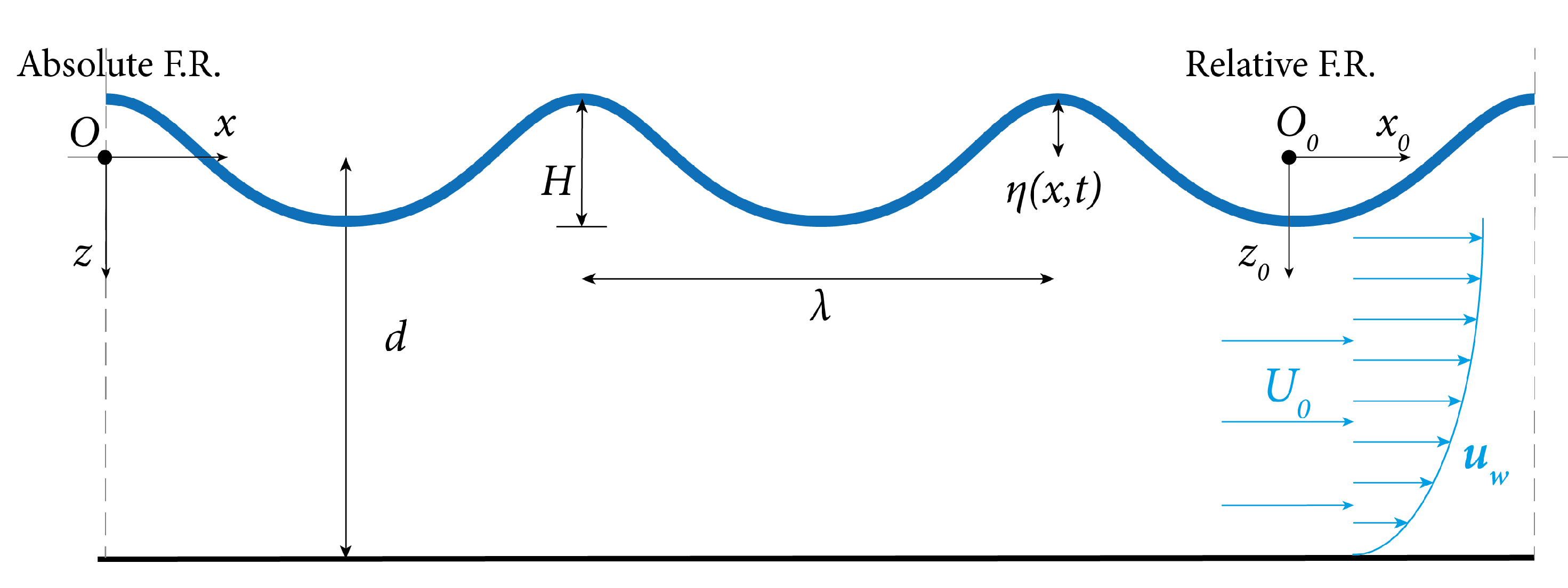
The inlet condition is imposed by combining the presence of the current, constant over depth with velocity U 0 , and the wave pattern encountered by the craft. To reconstruct the latter field, let us consider two frames of reference (FRs) [62]: one moving with the current, namely relative FR { O 0 , x 0 , y 0 } , and one fixed, the absolute FR { O , x , y } (Figure 2).
According to the linear wave theory assumptions, which are verified by the experimental conditions (Table 2), the wave travels unmodified in the relative FR, and its angular frequency ω shifts with respect to the absolute FR according to the Doppler’s effect:
ω A = ω R + κ U 0
where κ is the wave number, and with clear significance of the subscripts. Depending on the available data, this relationship, along with the dispersion relation, may be used to calculate the modified characteristics of the wave in the presence of the current. In the present work, the velocity of the current (towing speed), the generated angular wave frequency, and the wave number are provided. In deep-water conditions, the dispersion relation reads:
ω G E N 2 = g κ
and
λ = 2 π / κ
ω G E N = 2 π / T G E N
f G E N = 1 / T G E N
where λ is the wavelength, and T G E N and f G E N are the wave period and frequency as generated by the paddle. Considering the adopted numerical solution, the hull is fixed in the x direction, representing the absolute FR, which is, in general, the one to be considered for developing inlet conditions. The wave perceived by the craft has to keep all of the same features as the experimental one; thus, with κ unchanged, the encountered frequency corresponds to:
f E N C = f G E N + U 0 / λ
which can be obtained by substituting Equations (16)–(19) in Equation (15). The correspondence between the subscripts ( R G E N and A E N C ) results clear. With all of the wave parameters known, the velocity field u ( x , z , t ) = { u ( x , z , t ) , w ( x , z , t ) } and the free surface elevation η ( x , t ) can be obtained from a first-order velocity potential function, which includes the steady current [62]:
φ ( x , z , t ) = U 0 x + A cosh ( κ ( d + z ) ) cos ( κ x ω t )
Applying the boundary conditions (dynamic and kinematic free-surface boundary conditions) and retaining all of the linear terms, the functions of interest become:
η ( x , t ) = H 2 cos ( κ x ω t )
u ( x , z , t ) = φ x = U 0 + A cosh ( κ ( d + z ) ) cosh ( κ d ) sin ( κ x ω t )
w ( x , z , t ) = φ z = A sinh ( κ ( d + z ) ) cosh ( κ d ) cos ( ω t κ x )
A = g H κ 2 ω ( 1 U 0 / C 1 )
where C 1 = ω / κ . Please note that the presented fields are not dependent on the y coordinate as they are constant along the transversal dimension of the 3D domain. Generally, the wave is modified by the presence of the current, which, in the following conditions, stretches the wave, causing increments in the wavelength [62,63] and possible reductions in the wave amplitude. However, for the purpose of this simulation, the free-surface elevation in Equation (22) and the wave characteristics are imposed, so that they match the experimental wave pattern, which, in reality, does not interact with any current. The wavelength, which is unknown in the wave analysis if T, H, d, and U 0 are given, here depends on the deep-water dispersion relation in Equation (16) and is kept unchanged, i.e., the Doppler effect does not modify κ . The wave period, indeed, is modified through Equation (20) to obtain T E N C = 1 / f E N C , which mimics the period that would be perceived by an observer standing on the advancing hull. Table 3 summarizes the equivalence of the conditions assigned in the experimental towing tank and in the numerical wave flume.
It follows, moreover, that the parameter A assumes the form of Equation (25) to satisfy the linearized Bernoulli equation (dynamic free surface boundary condition), including the current velocity U 0 [62]. It is necessary to consider that the aforementioned result is obtained with the assumptions of limited current velocities. The carriage speed, however, is relevant, so viscous effects start to play a role in wave propagation, usually causing skewness in the direction of the current. Nevertheless, at the inlet boundary, the velocity profiles prescribed are obtained from a potential that fulfills the lateral periodic boundary conditions φ ( x , z , t ) = φ ( x , z , t + T ) . The simultaneous generation of waves and the current thus cancels the excess of viscous drag induced by the swift mass transport and results in a wave profile that smoothly matches the one imposed in the experimental facility.

4.2. DualSPHysics Framework

DualSPHysics allows for reproducing the hull–wave interaction in a fully Lagrangian domain, within which the resolution is defined upon the initial inter-particle distance dp [m]. The resolution, along with a properly defined coefficient ( c o e f h = 1.5 was adopted in this work), also dictates the dimension of the smoothing length h = c o e f h ( 3 d p 2 ) 1 / 2 and thus the radius of the interaction between the particles. The numerical wave flume specifically implemented is presented in Figure 3. It was developed using open boundaries [48] to allow for current and wave propagation in the x direction, and with periodic boundaries [64] in the y direction; the latter conditions ensure the absence of side wall effects. No-slip boundary conditions are also enforced at the bottom. The computational domain dimensions are approximately two wavelengths long to ensure correct wave propagation and absorption, approximately three hull beams wide, and with a depth equal to 2 m, corresponding to half of the experimental depth. In deep-water conditions, in fact, the velocity field is almost completely developed in the uppermost half of the water column, and the limited error related is generously rewarded with a sensible reduction in the computational time. The open-boundary conditions adopted permit a sensible undersizing of the SPH domain with respect to the typical computational model suggested in the literature, which is crucial to unleashing the accuracy of the fluid–solid solver with a suitable resolution.
Particles motion (Figure 3, left hand) is extrapolated from a spatial grid [65] where the fields of interest Equations (22)–(24) are imposed in time. Several layers of SPH buffer particles are located at the inlet, enough in number to cover at least the kernel radius. Along with the physical information imposed ( u ( x , z , t ) , η ( x , t ) ), others can be extrapolated from the fluid domain (fluid density, ρ ). Similarly, in the outlet zone (Figure 3, right hand), the outward flow velocity is fixed and equal to the current velocity U 0 , but both the depth and fluid density are extrapolated.
The setup includes a Relaxation Zone (RZ) [66] to smoothly convert the perturbed flow caused by the planing hull and the interaction of waves-related ( u w ) and current ( U 0 ) velocities into a steady horizontal current, as sketched in Figure 3, right-hand side. The RZ is typically implemented for wave generation or absorption, where a weighting function C = C ( x , ψ , β ) , shaped upon two parameters ψ and β , constrains the particles to follow the imposed velocity field. Half of this bell-shaped curve, instead, was used in this work, as the RZ was placed with the maximum of C coincident with the outlet boundary layer, whereas the other half lay ineffective outside the computational domain. In this way, the RZ nullifies the orbital velocities components, together with the disturbance created by the keel, and re-establishes the current with velocity U 0 . The latter velocity eventually matches the imposed outlet condition. Suitable values for ψ and β lie within the ranges of 0.05÷ 0.15 and 5 ÷ 8 , respectively. The sensitivity of the RZ to these parameters is related to the ratio between the orbital velocities and the intensity of the current. When the magnitude of U 0 is considerably greater than the peak values of ( u w ), as it is in this investigation, the shape of the C function may vary substantially without affecting the wave absorption and the effectiveness of the outlet.
The vessel, as well as the whole domain, is discretized with SPH particles, filling the original geometry file. The STL surface (Figure 3, center) individuates the interface layer for normal computation (see Section 2.4) to ensure a perfect match between the experimental and numerical model dimensions, whereas the outermost level of solid particles is generated at a small distance inside the aforementioned surface. The physical characteristics of the simulated hull correspond to the values of Table 1.

5. Results

In this section, the outcomes of the SPH simulations are presented. Firstly, a roll decay test was performed. Following that, the validation process was completed by 2D empty tank tests for wave propagation and 3D hull heave and pitch motion comparisons for the cases of interest individuated in Table 2. Finally, the evaluation of the hull’s RAO depicts the overall performance of the proposed methodology.

5.1. Roll Decay Test

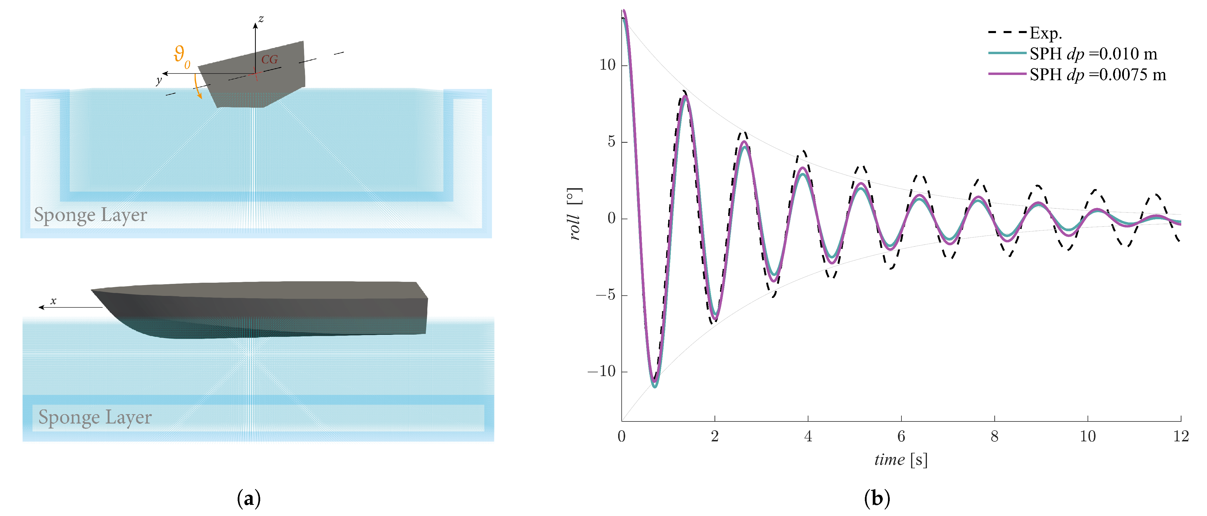
To assess the effectiveness of the numerical twin of the C2s hull, a free roll decay test was performed and paired with the corresponding measurements from the experimental campaign carried out at the University of Naples “Federico II”. The use of a numerical decay test to assess the roll damping of the vessel is still not diffused, especially for planing hulls, as it is characterized by strong non-linearity, and the results are mightily influenced by the characteristics of the code used, the initial conditions, and modeling (e.g., the Degrees of Freedom (DOFs) of the hull) [67]. In the present case, the motion was restricted to allow for only rotation around the x axis (one degree of freedom), and the vessel was initially tilted at an angle ϑ 0 = 13 . 63 with respect to the reference frame centered in its center of gravity. The latter coordinates, along with the roll gyradius utilized, are available in Table 1. The use of sponge layers (Figure 4a) to absorb the perturbations induced by the roll motion avoid any reflection from the boundaries and allow for a sensible reduction in the computational domain with respect to the experimental tank, thus alleviating the workload. The comparison is presented in Figure 4b, showing two different SPH resolutions. The signals are in almost perfect agreement, whereas the decay of the numerical roll is swifter and only partially attenuated by the higher resolution. The experimental damping factor referred to the first three oscillations, in fact, is ξ E X P = 6.4% , whereas the numerical counterparts are ξ S P H = 7.9% for dp = 0.01 m and ξ S P H = 7.4% for dp = 0.075 m. This is attributable to at least two factors:
  • Single-DOF numerical roll tests show faster decay terms with respect to multiple-DOF results [67], as the complete reproduction of the complex and non-linear phenomenon is impossible to achieve through strict motion assumptions;
  • The SPH resolution strongly influences the results as the motion amplitude decreases, causing a noticeable increase in the numerical damping when the arc covered by the hull approaches the dp value [42].
Higher resolutions are expected to strongly improve the agreement in terms of amplitude, as well as freeing multiple DOFs. Both strategies imply increasing the computational demand.

5.2. Waves over Steady Current

The evaluation of the fluid phase motion was performed in 2D, since the flow characteristics are bi-dimensional even in the 3D domain, the motion fields being imposed unvaried along the y direction (see Section 4.1). Three of the wave conditions reported in Table 2 are evaluated in this section, following the discussion of Section 4.1. The underlying current travels at U 0 = 3.5 m/s, constant along the water depth, resulting in modified frequencies f E N C encountering the hull. Figure 5 depicts the free-surface elevation over several periods. As usual in SPH validations of water waves, the number of particles per wave amplitude is the crucial parameter, more so than the resolution itself. With the coarser resolution ( d p = 0.010 m), the smallest amplitude (Figure 5a) is covered by 4 particles, which is sensibly under the threshold of H / d p = 10 recommended in most of the available literature [68,69]. Notwithstanding, the agreement is good and both crest and troughs are well reproduced. It is worth noting that negligible improvements are visible with d p = 0.0075 m, which corresponds, for Case 2 (Figure 5a), to H / d p 6 . However, the wave conditions corresponding to Case 4, Figure 5c, show a constant overshooting of the crests; this wave is characterized by a small period T E N C and relatively small wavelength. The wave steepness is hence pronounced and it sharpens the limitations of this approach. It follows that, within the evaluation process of the hull dynamics, the wave component can be considered as effective overall, even with the largest value of dp, especially for limited wave steepness values. For high steepness, instead, divergence in the results may be expected, with the numerical model expected to slightly overestimate the motion amplitude. Further discrepancies in the results between the two resolutions would be attributable to the better computation of the keel–wave interaction and to the more precise discretization of the hull geometry, as the initial inter-particle distance diminishes. For the sake of numerical feasibility, finer resolutions are not considered, while coarser resolutions would result in an insufficient number of particles that discretize the wave. The wave propagation over the steady current does not add significant uncertainties about the hull dynamics, as the theoretical profile is satisfactorily matched by the proposed SPH resolutions, and any deviation in the result can be addressed. As previously mentioned in Section 4.1, in Figure 5, there is little to no evidence of skewness caused by the current-induced drag forces, guaranteeing that the encountered wave is shaped like the ones generated in the experimental tests.

5.3. Hull Motions

The hull response with respect to the validated wave conditions is reported in Figure 6 along with the experimental series. In the following charts, the first instants of the simulation, where the response of the vessel is significantly unsteady, are ignored (as in [14]). The present DualSPHysics simulations accurately match the motion phase for any wave condition, and, in general, offer acceptable results regarding the amplitude of the two investigated motions. Despite the overall accuracy of the proposed SPH setup, the excitation function (i.e., the encountered wave train) still determines the performances of the numerical reproduction, as the physics of the wave–hull interaction changes accordingly. Further considerations could be made, in fact, with respect to the wave steepness and encountered frequency, which could represent relevant parameters for estimating the capabilities of the SPH method. The presented graphs cover different regular head waves: the cases are listed as per decreasing relative wavelength and encountered period (see Table 2). Case 2 features a relatively small wave height and steepness: the heave amplitude (Figure 6a) is slightly underestimated by the present SPH model, whereas the pitch better matches the experimental results (Figure 6b). On the contrary, for Case 3, which is characterized by the largest wave amplitude considered, as well as considerable wave steepness, SPH performs better in terms of vertical motions (Figure 6c), whereas constantly undershoots the negative pitch peaks (Figure 6d). The last case’s charts instead show a constant overestimation of the experimental series, negligible in the case of heave (Figure 6e) but slightly more pronounced when concerning the pitch (Figure 6f). As previously stated, the wave pattern encountered by the hull in Case 4 presented higher crests than the experimental counterpart: this can explain the partial jeopardizing of the SPH results, especially in terms of the pitch motion. The latter dynamics, in fact, are magnified by the relatively high wave steepness and high frequency of Case 4, which trigger the rotational inertial effects.

5.4. Overall Performance

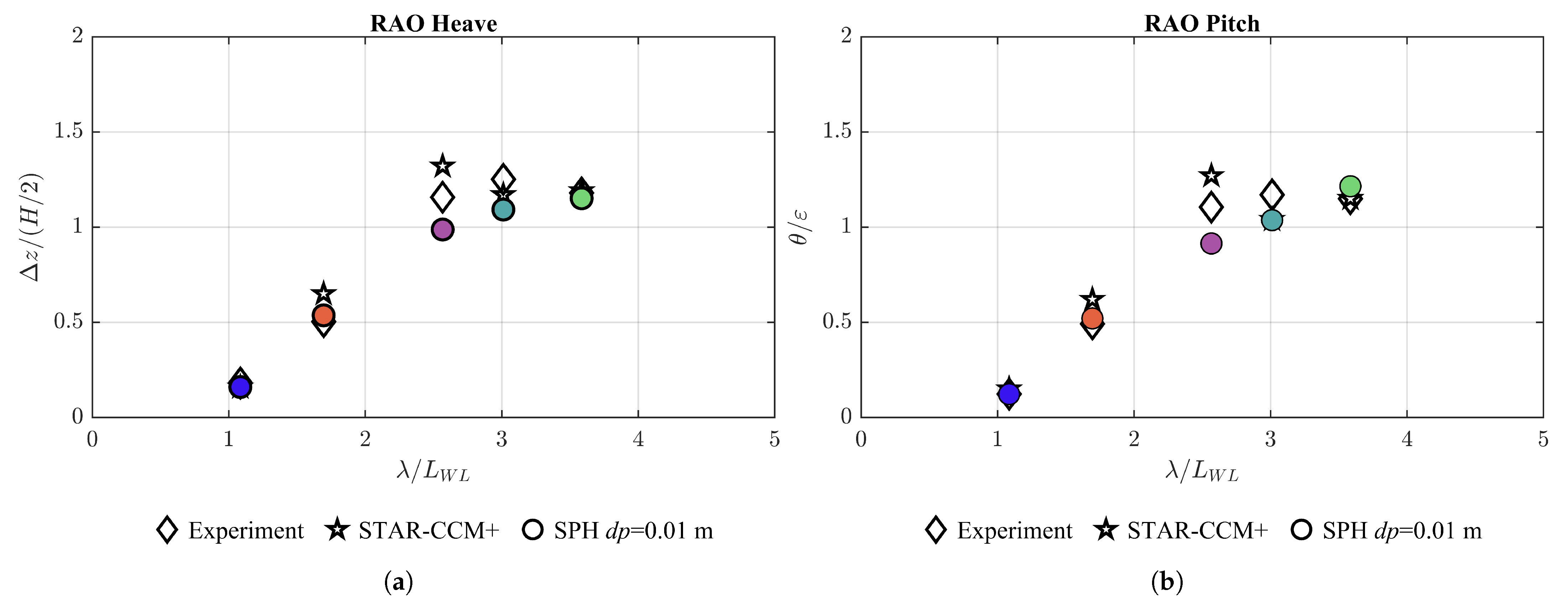
The performance of the model in reproducing heave and pitch motion within the sample of wave conditions simulated is presented in Figure 7, which features the numerical results from Tavakoli et al., 2020 [14] as well. The latter results are performed with the grid-based RANS solver STAR-CCM+, which underwent a grid refinement process [14]. The displayed outcomes of [14] can thus be considered the best achievable with such an approach. The Response Amplitude Operator (RAO) is computed by averaging the motion amplitude of experimental and numerical series with respect to the first harmonic amplitude ( H / 2 for first-order waves) for the heave and with respect to the wave steepness ε = κ ( H / 2 ) for the pitch. The horizontal axis in Figure 7 reports the wavelength-to-hull’s-waterline-length ratio (’Relative wavelength’ in Table 2), and, for ease of reference, each case is plotted with its identifying color. The percentage error related to the numerical RAO values is, moreover, reported in Table 4, and calculated as:
e N U M = R A O N U M R A O E X P R A O E X P
where the subscript N U M conveniently indicates the STAR-CCM+ or SPH results. The SPH model shows consistent agreement in all of the wave conditions but performs outstandingly in the limits of the domain: in the inertia region ( λ < 2 ), where the RAO is narrow, the model predictions are close to the experimental measurements, just like as in the stiffness region ( λ > 3.5 ). The largest deviation is observed at the peak of the RAO, in the so-called damping region. This result can be considered consistent with the outcomes of Section 5.1, where an excess of numerical damping has been recognized. In addition, the SPH model shows a comparable agreement with the STAR-CCM+ results for the largest values of excitation, whereas it performs similarly to the grid-based solver at the edges of the relative wavelength domain. A similar underestimation of the RAO peaks in the damping region can also be found in other numerical simulations of planing hulls [70].
Further considerations can concern the virtual mass effect, which is related to the fluid mass that accelerates with the vessel during its motion and is difficult to capture even with CFD models. Relying on high dynamic lifting forces to glide over the water surface, a significant rate of the increased response, which could constitute a source of discrepancy between physical and numerical methods, could be attributed to the additional fluid mass disrupted by the planing vessel. Moreover, the continued changes in the extension of the wetted surface, resulting in highly variable hydrodynamic loads, make the consequential virtual added inertia a crucial parameter in estimating the motion amplitudes, especially when the response of the vessel is wider than the wave amplitude.
Another aspect that may help to deepen the understanding of the divergences observed in RAO responses is the uncertainty in the reproduction of the forcing condition acting on the hull. During the experiment, in fact, the hull may face wave trains, which present slight differences in between consecutive crests and troughs with respect to the theoretical free-surface obtained via linear wave theory imposed in CFD simulations. When the wave condition is located within the previously defined damping region, the craft response is easily triggered and presents significant components due to higher harmonics. Thus, experimental discrepancies, obviously acceptable in terms of magnitude, may cause measurable changes in the hull’s response that are not directly accounted for by the response amplitude operators. More accurate analyses should be carried out to address this uncertainty and clarify the source of disagreement, but they are clearly outside the scope of this work.
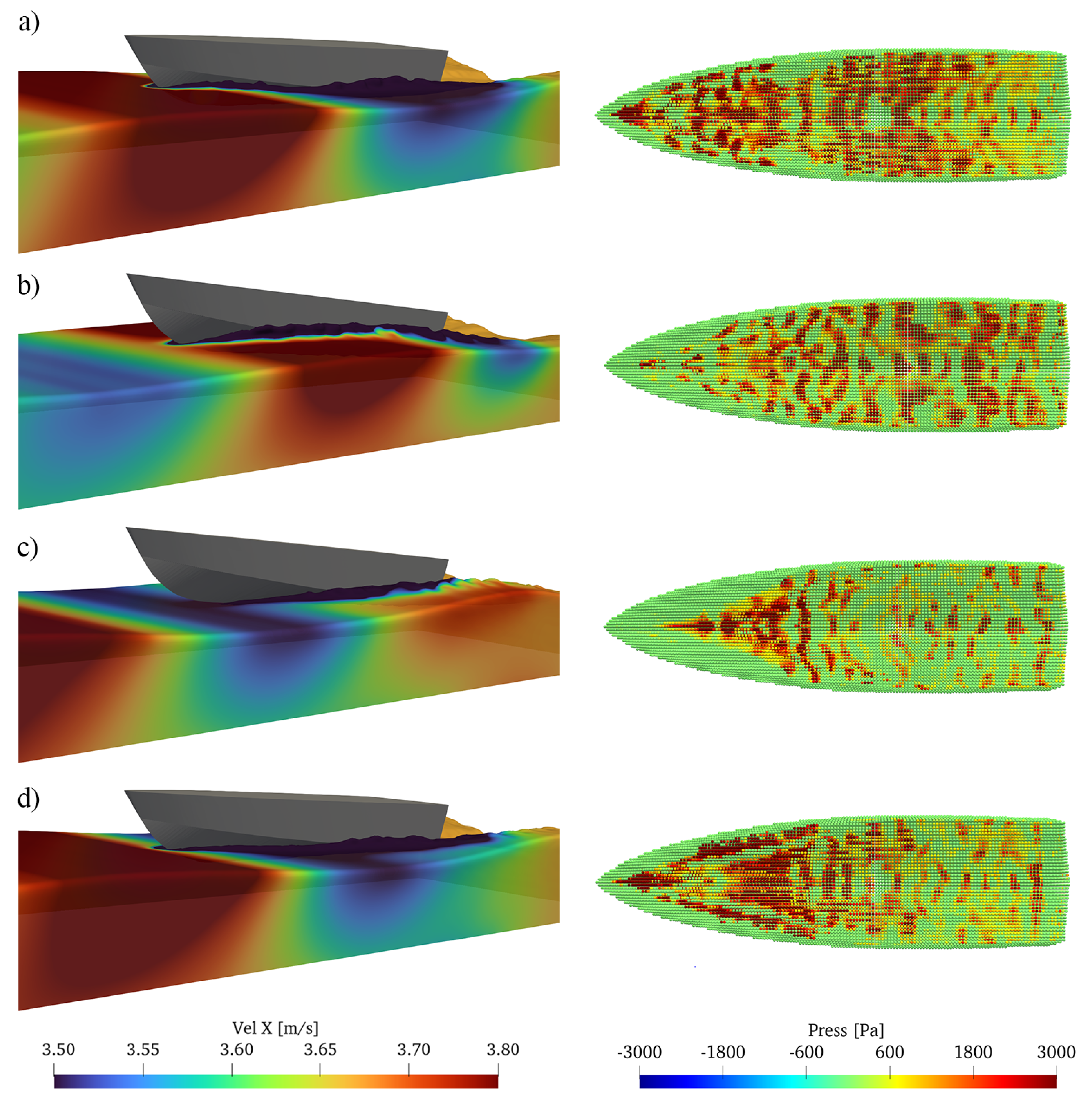
Figure 8 further clarifies the recognizable motion pattern of the planing hull, showing four distinct phases:
(a)
The vessel approaches the incoming wave and the lift forces increase—the keel is almost completely wetted;
(b)
The hull’s bow raises after the large hydrodynamic forces toward the maximum trim angle, and the wetted surface tends to its minimum;
(c)
The wave trough approaches as the vessel bow is completely lifted, and the water–keel interface is minimized;
(d)
The gravitational force guides the hull downward right before the next wave crest, causing its slamming and a consequential sudden increase in pressure on the keel panels, particularly in the chine regions.
Numerical models, in general, exhibit diminished forces in these crucial transition phases and tend to disregard the motion amplifications that the vessels usually experience. Excessive numerical damping and a lack of added mass could jeopardize the performance of CFD codes when high responses come into play. A more careful treatment of the fluid viscosity, together with further investigations of the hull dynamic properties in the CFD frameworks (i.e., its discretization) could improve the performance of the solver in accurately reproducing the flow around the keel and thus the whole unsteady phenomenon.

6. Conclusions

This work dealt with validating the proposed methodology within an SPH-based framework for the simulation of a planing hull in regular waves. A novel numerical wave flume was implemented in DualSPHysics in order to reproduce the flow conditions around a vessel, reproduce the towing process with constant velocity, and face incoming waves. The towing speed was represented in the numerical setup by a steady current, while the wave frequency was adjusted to match the encountered frequency as in the experimental tank. The flow features were drawn from a first-order approximation of a velocity potential, which includes a steady current and is imposed at the inlet boundary. The wave propagates for one wavelength, then interacts with the vessel, whose degrees of freedom are restricted to heave and pitch motion; then, the wave is dissipated by a combination of a relaxation zone and an outlet buffer area; both provided negligible reflection. The proposed setup showed consistency in both wave propagation and hull–wave interaction, being as accurate as other established proprietary CFD solvers, and even outperforming them in particular wave conditions. In summary, this approach represents reliable support for investigating the motion of planing hulls in unsteady conditions, for which empirical and analytical models usually fall short.
We conclude that the SPH method is effective in addressing planing craft response for the tested wave conditions in both phase coupling and the motion amplitude, though with different exactitudes. The errors are limited to the peaks of the response of the planing hull in the identified damping region, where most of the numerical approaches proposed in the literature fail to capture the amplification in the hull vertical displacement caused by waves of a relative wavelength close to three. The divergence, however, is in the range of 10 % and can be ascribed to a lack of virtual mass effects, which are most evident with large flow disruptions, and excessive numerical damping, also recognized in the roll damping analysis performed on the C2s hull. Future work will feature further numerical investigation on the influence of numerical damping, resolution, and different viscosity treatments (e.g., the laminar viscosity model [71]). As part of the next numerical campaign, wider ranges of Froude’s numbers will be tested to analyze the model performance in different planing regimes. The numerical framework presented here would eventually be able to tackle the hydroelastic analysis of the hull panels using the methodology proposed in [72] or, ultimately, considering the surface of the hull as being composed of elastic material using the approach developed in [73].

Author Contributions

Conceptualization, S.C., B.T. and S.M.; methodology, S.C., B.T. and C.A.; software, I.M.-E. and J.M.D.; validation, S.C.; formal analysis, S.C., B.T. and S.M.; investigation, S.C.; resources, G.V.; data curation, S.C., B.T. and S.M.; writing—original draft preparation, S.C., S.M.; writing—review and editing, S.C., B.T., S.M., I.M.-E., C.A., J.M.D. and G.V.; visualization, S.C.; supervision, G.V., S.M.; project administration, G.V. and S.M.; funding acquisition, G.V. and S.M. All authors have read and agreed to the published version of the manuscript.

Funding

I.M.-E. and J.M.D. acknowledge the support of the project SURVIWEC PID2020-113245RB-I00 financed by MCIN/AEI/10.13039/501100011033, of the project ED431C 2021/44 “Programa de Consolidación e Estructuración de Unidades de Investigación Competitivas” financed by Xunta de Galicia, Consellería de Cultura, Educación e Universidade, and of the Grant TED2021-129479A-I00 funded by MCIN/AEI/ 10.13039/501100011033 and by the “European Union NextGenerationEU/PRTR”. I.M.-E. acknowledges funding from Xunta de Galicia under “Programa de axudas á etapa predoutoral da Consellería de Cultura, Educación e Universidades da Xunta de Galicia” (ED481A-2021/337). C.A. acknowledges funding from the Spanish government and the European Social Found (ESF) under the program “Ramón y Cajal 2020” (RYC2020-030197-I/AEI/10.13039/501100011033).

Institutional Review Board Statement

Not applicable.

Informed Consent Statement

Not applicable.

Data Availability Statement

Data sharing not applicable.

Conflicts of Interest

The authors declare no conflict of interest.

Abbreviations

The following abbreviations are used in this manuscript:
2DTwo-Dimensional
3DThree-Dimensional
CFDComputational Fluid Dynamics
DBCDynamic Boundary Condition
DOFDegree of Freedom
FRFrame of Reference
F r B Beam Froude Number
ITTCInternational Towing Tank Conference
mDBCModified Dynamic Boundary Condition
NSSNaples Systematic Series
RANSReynolds-Averaged Navier–Stokes
RAOResponse Amplitude Operator
R e Reynolds Number
RZRelaxation Zone
SPHSmoothed Particle Hydrodynamics
STLStandard Triangle Language
WCSPHWeakly Compressible SPH

References

  1. Ulstein, T.; Faltinsen, O.M. Two-dimensional unsteady planing. J. Ship Res. 1996, 40, 200–210. [Google Scholar] [CrossRef]
  2. Ghadimi, P.; Tavakoli, S.; Dashtimanesh, A. Coupled heave and pitch motions of planing hulls at non-zero heel angle. Appl. Ocean. Res. 2016, 59, 286–303. [Google Scholar] [CrossRef]
  3. De Luca, F.; Pensa, C. The Naples Systematic Series–Second part: Irregular waves, seakeeping in head sea. Ocean. Eng. 2019, 194, 106620. [Google Scholar] [CrossRef]
  4. Abrate, S. Hull Slamming. Appl. Mech. Rev. 2011, 64, 1003. [Google Scholar] [CrossRef]
  5. Begovic, E.; Bertorello, C.; Pennino, S. Experimental seakeeping assessment of a warped planing hull model series. Ocean. Eng. 2014, 83, 1–15. [Google Scholar] [CrossRef]
  6. Fridsma, G. A Systematic Study of the Rough-Water Performance of Planing Boats: Irregular Waves—Part 2; Technical Report; David W. Taylor Naval Ship Research and Development Center; Defense Technical Information Center: Fairfax, VA, USA, 1971.
  7. Grigoropoulos, G.; Loukakis, T. Resistance and seakeeping characteristics of a systematic series in the pre-planing condition (Part I). Trans. SNAME 2002, 110, 77–113. [Google Scholar]
  8. Soletic, L. Seakeeping of a Systematic Series of Planing Hulls. Ph.D. Thesis, Stevens Institute of Technology, Hoboken, NJ, USA, 2009. [Google Scholar]
  9. De Luca, F.; Pensa, C. The Naples warped hard chine hulls systematic series. Ocean. Eng. 2017, 139, 205–236. [Google Scholar] [CrossRef]
  10. Zarnick, Z.E. A Nonlinear Mathematical Model of Motions of a Planing Boat in Regular Waves; David W. Taylor Naval Ship Research and Development Center; Defense Technical Information Center: Fairfax, VA, USA, 1978. [CrossRef]
  11. Pennino, S.; Begovic, E.; Bertorello, C.; Scamardella, A. Time domain assessment of vertical motions of planing hulls. In Technology and Science for the Ships of the Future: Proceedings of NAV 2018: 19th International Conference on Ship & Maritime Research, Trieste, Italy, 20–22 June 2018; IOS Press: Amsterdam, The Netherlands, 2018; p. 472. [Google Scholar]
  12. Kahramanoglu, E.; Pennino, S.; Yilmaz, H. Numerical evaluation of hydrodynamic characteristics of planing hulls by using a hybrid method. Proc. Inst. Mech. Eng. Part M J. Eng. Marit. Environ. 2021, 235, 344–355. [Google Scholar] [CrossRef]
  13. Bi, X.; Zhuang, J.; Su, Y. Seakeeping Analysis of Planing Craft under Large Wave Height. Water 2020, 12, 20. [Google Scholar] [CrossRef]
  14. Tavakoli, S.; Niazmand Bilandi, R.; Mancini, S.; De Luca, F.; Dashtimanesh, A. Dynamic of a planing hull in regular waves: Comparison of experimental, numerical and mathematical methods. Ocean. Eng. 2020, 217, 107959. [Google Scholar] [CrossRef]
  15. Tezdogan, T.; Demirel, Y.K.; Kellett, P.; Khorasanchi, M.; Incecik, A.; Turan, O. Full-scale unsteady RANS CFD simulations of ship behaviour and performance in head seas due to slow steaming. Ocean. Eng. 2015, 97, 186–206. [Google Scholar] [CrossRef]
  16. Pacuraru, F.; Domnisoru, L.; Pacuraru, S. On the Comparative Seakeeping Analysis of the Full Scale KCS by Several Hydrodynamic Approaches. J. Mar. Sci. Eng. 2020, 8, 962. [Google Scholar] [CrossRef]
  17. International Towing Tank Conference (ITTC). The Specialist Committee on Model Test of High Speed Marine Vehicles; Final Report and Recommendations to the 22nd ITTC; ITTC: Zürich, Switzerland, 2014. [Google Scholar]
  18. Rakhsha, M.; Kees, C.E.; Negrut, D. Lagrangian vs. Eulerian: An analysis of two solution methods for free-surface flows and fluid solid interaction problems. Fluids 2021, 6, 460. [Google Scholar] [CrossRef]
  19. Wang, S.; González-Cao, J.; Islam, H.; Gómez-Gesteira, M.; Guedes Soares, C. Uncertainty estimation of mesh-free and mesh-based simulations of the dynamics of floaters. Ocean. Eng. 2022, 256, 111386. [Google Scholar] [CrossRef]
  20. Liu, G.; Liu, M. Smoothed Particle Hydrodynamics; World Scientific: Singapore, 2003. [Google Scholar] [CrossRef]
  21. Monaghan, J.J. Smoothed Particle Hydrodynamics. Annu. Rev. Astron. Astrophys. 1992, 30, 543–574. [Google Scholar] [CrossRef]
  22. Violeau, D.; Rogers, B. Smoothed particle hydrodynamics (SPH) for free-surface flows: Past, present and future. J. Hydraul. Res. 2016, 54, 1–26. [Google Scholar] [CrossRef]
  23. Gotoh, H.; Khayyer, A. On the state-of-the-art of particle methods for coastal and ocean engineering. Coast. Eng. J. 2018, 60, 79–103. [Google Scholar] [CrossRef]
  24. Manenti, S.; Wang, D.; Domínguez, J.; Li, S.; Amicarelli, A.; Albano, R. SPH Modeling of Water-Related Natural Hazards. Water 2019, 11, 1875. [Google Scholar] [CrossRef]
  25. Amicarelli, A.; Manenti, S.; Albano, R.; Agate, G.; Paggi, M.; Longoni, L.; Mirauda, D.; Ziane, L.; Viccione, G.; Todeschini, S.; et al. 9.0.0: A Computational Fluid Dynamics research code, based on the Smoothed Particle Hydrodynamics mesh-less method. Comput. Phys. Commun. 2020, 250, 107157. [Google Scholar] [CrossRef]
  26. Luo, M.; Khayyer, A.; Lin, P. Particle methods in ocean and coastal engineering. Appl. Ocean. Res. 2021, 114, 102734. [Google Scholar] [CrossRef]
  27. Khayyer, A.; Rogers, B.D.; Zhang, A.M. Preface: Special Issue on Advances and Applications of SPH in Ocean Engineering. Appl. Ocean. Res. 2022, 118, 103028. [Google Scholar] [CrossRef]
  28. Marrone, S.; Colagrossi, A.; Antuono, M.; Lugni, C.; Tulin, M.P. A 2D+t SPH model to study the breaking wave pattern generated by fast ships. J. Fluids Struct. 2011, 27, 1199–1215. [Google Scholar] [CrossRef]
  29. Marrone, S.; Bouscasse, B.; Colagrossi, A.; Antuono, M. Study of ship wave breaking patterns using 3D parallel SPH simulations. Comput. Fluids 2012, 69, 54–66. [Google Scholar] [CrossRef]
  30. Dashtimanesh, A.; Ghadimi, P. A three-dimensional SPH model for detailed study of free surface deformation, just behind a rectangular planing hull. J. Braz. Soc. Mech. Sci. Eng. 2013, 35, 369–380. [Google Scholar] [CrossRef]
  31. Tafuni, A.; Sahin, I.; Hyman, M. Numerical investigation of wave elevation and bottom pressure generated by a planing hull in finite-depth water. Appl. Ocean. Res. 2016, 58, 281–291. [Google Scholar] [CrossRef]
  32. Brizzolara, S.; Viviani, M.; Savio, L. Comparison of SPH and RANSE methods for the evaluation of impact problems in the marine field. In Proceedings of the 8th World Congress on Computational Mechanics (WCCM8), Venice, Italy, 30 June–4 July 2008. [Google Scholar]
  33. Cheng, H.; Ming, F.; Sun, P.; Sui, Y.; Zhang, A.M. Ship hull slamming analysis with smoothed particle hydrodynamics method. Appl. Ocean. Res. 2020, 101, 102268. [Google Scholar] [CrossRef]
  34. Domínguez, J.; Fourtakas, G.; Altomare, C.; Canelas, R.; Tafuni, A.; García Feal, O.; Martínez-Estévez, I.; Mokos, A.; Vacondio, R.; Crespo, A.; et al. DualSPHysics: From fluid dynamics to multiphysics problems. Comput. Part. Mech. 2022, 9, 867–895. [Google Scholar] [CrossRef]
  35. Domínguez, J.M.; Crespo, A.J.; Gómez-Gesteira, M. Optimization strategies for CPU and GPU implementations of a smoothed particle hydrodynamics method. Comput. Phys. Commun. 2013, 184, 617–627. [Google Scholar] [CrossRef]
  36. Domínguez, J.; Crespo, A.; Hall, M.; Altomare, C.; Wu, M.; Stratigaki, V.; Troch, P.; Cappietti, L.; Gómez-Gesteira, M. SPH simulation of floating structures with moorings. Coast. Eng. 2019, 153, 103560. [Google Scholar] [CrossRef]
  37. Martínez-Estévez, I.; Domínguez, J.; Tagliafierro, B.; Canelas, R.; García-Feal, O.; Crespo, A.; Gómez-Gesteira, M. Coupling of an SPH-based solver with a multiphysics library. Comput. Phys. Commun. 2023, 283, 108581. [Google Scholar] [CrossRef]
  38. Tagliafierro, B.; Montuori, R.; Vayas, I.; Ropero-Giralda, P.; Crespo, A.; Domìnguez, J.; Altomare, C.; Viccione, G.; Gòmez-Gesteira, M. A new open source solver for modelling fluid-structure interaction: Case study of a point-absorber wave energy converter with a power take-off unit. In Proceedings of the 11th International Conference on Structural Dynamics, Athens, Greece, 23–26 November 2020. [Google Scholar] [CrossRef]
  39. Ropero-Giralda, P.; Crespo, A.J.; Tagliafierro, B.; Altomare, C.; Domínguez, J.M.; Gómez-Gesteira, M.; Viccione, G. Efficiency and survivability analysis of a point-absorber wave energy converter using DualSPHysics. Renew. Energy 2020, 162, 1763–1776. [Google Scholar] [CrossRef]
  40. Tagliafierro, B.; Martínez-Estévez, I.; Domínguez, J.M.; Crespo, A.J.; Göteman, M.; Engström, J.; Gómez-Gesteira, M. A numerical study of a taut-moored point-absorber wave energy converter with a linear power take-off system under extreme wave conditions. Appl. Energy 2022, 311, 118629. [Google Scholar] [CrossRef]
  41. Tagliafierro, B.; Martínez-Estévez, I.; Crego-Loureiro, C.; Domínguez, J.; Crespo, A.; Coe, R.; Bacelli, G.; Viccione, G.; Gómez-Gesteira, M. Numerical Modeling of Moored Floating Platforms for Wave Energy Converters Using DualSPHysics. In Proceedings of the 41st International Conference on Offshore Mechanics and Arctic Engineering (OMAE), Hamburg, Germany, 5–10 June 2022; p. 8. [Google Scholar]
  42. Tagliafierro, B.; Karimirad, M.; Martínez-Estévez, I.; Domínguez, J.M.; Viccione, G.; Crespo, A.J.C. Numerical Assessment of a Tension-Leg Platform Wind Turbine in Intermediate Water Using the Smoothed Particle Hydrodynamics Method. Energies 2022, 15, 3993. [Google Scholar] [CrossRef]
  43. Tagliafierro, B.; Karimirad, M.; Martínez-Estévez, I.; Domínguez, J.; Crespo, A.; Gómez-Gesteira, M.; Viccione, G. Preliminary study of floating offshore wind turbines motions using the Smoothed Particle Hydrodynamics method. In Proceedings of the 41st International Conference on Offshore Mechanics and Arctic Engineering (OMAE), Hamburg, Germany, 5–10 June 2022; p. 3993. [Google Scholar]
  44. Mintu, S.; Molyneux, D.; Colbourne, B. Full-scale SPH simulations of ship-wave impact generated sea spray. Ocean. Eng. 2021, 241, 110077. [Google Scholar] [CrossRef]
  45. Tagliafierro, B.; Mancini, S.; Ropero-Giralda, P.; Domínguez, J.M.; Crespo, A.J.C.; Viccione, G. Performance assessment of a planing hull using the smoothed particle hydrodynamics method. J. Mar. Sci. Eng. 2021, 9, 244. [Google Scholar] [CrossRef]
  46. Hosseini, A.; Tavakoli, S.; Dashtimanesh, A.; Sahoo, P.K.; Korgesaar, M. Performance Prediction of a Hard-Chine Planing Hull by Employing Different CFD Models. J. Mar. Sci. Eng.G 2021, 9, 481. [Google Scholar] [CrossRef]
  47. Pak, C.; Han, P.; Ri, K.; Ri, Y.; Hwang, I. Numerical analysis of the nonlinear free surface flow around an advancing ship using moving particle semi-implicit method. AIP Adv. 2021, 11, 035106. [Google Scholar] [CrossRef]
  48. Tafuni, A.; Domínguez, J.; Vacondio, R.; Crespo, A. A versatile algorithm for the treatment of open boundary conditions in Smoothed particle hydrodynamics GPU models. Comput. Methods Appl. Mech. Eng. 2018, 342, 604–624. [Google Scholar] [CrossRef]
  49. Siemens, P. STAR-CCM+ User Guide, Version 13.04.; Siemens PLM Software Inc.: Munich, Germany, 2019. [Google Scholar]
  50. Wendland, H. Piecewise polynomial, positive definite and compactly supported radial basis functions of minimal degree. Adv. Comput. Math. 1995, 4, 389–396. [Google Scholar] [CrossRef]
  51. Fourtakas, G.; Dominguez, J.M.; Vacondio, R.; Rogers, B.D. Local uniform stencil (LUST) boundary condition for arbitrary 3-D boundaries in parallel smoothed particle hydrodynamics (SPH) models. Comput. Fluids 2019, 190, 346–361. [Google Scholar] [CrossRef]
  52. Monaghan, J.; Kos, A.; Issa, N. Fluid Motion Generated by Impact. J. Waterw. Port, Coastal, Ocean. Eng. 2003, 129, 250–259. [Google Scholar] [CrossRef]
  53. Canelas, R.B.; Domínguez, J.M.; Crespo, A.J.; Gómez-Gesteira, M.; Ferreira, R.M. A Smooth Particle Hydrodynamics discretization for the modelling of free surface flows and rigid body dynamics. Int. J. Numer. Methods Fluids 2015, 78, 581–593. [Google Scholar] [CrossRef]
  54. English, A.; Domínguez, J.; Vacondio, R.; Crespo, A.; Stansby, P.; Lind, S.; Chiapponi, L.; Gómez-Gesteira, M. Modified dynamic boundary conditions (mDBC) for general purpose smoothed particle hydrodynamics (SPH): Application to tank sloshing, dam break and fish pass problems. Comput. Part. Mech. 2022, 9, 911–925. [Google Scholar] [CrossRef]
  55. Crespo, A.; Gómez-Gesteira, M.; Dalrymple, R. Boundary conditions generated by dynamic particles in SPH methods. Comput. Mater. Contin. 2007, 5, 173–184. [Google Scholar]
  56. Zhang, F.; Crespo, A.; Altomare, C.; Domínguez, J.; Marzeddu, A.; Shang, S.p.; Gómez-Gesteira, M. DualSPHysics: A numerical tool to simulate real breakwaters. J. Hydrodyn. 2018, 30, 95–105. [Google Scholar] [CrossRef]
  57. Marrone, S.; Antuono, M.; Colagrossi, A.; Colicchio, G.; Le Touzé, D.; Graziani, G. δ-SPH model for simulating violent impact flows. Comput. Methods Appl. Mech. Eng. 2011, 200, 1526–1542. [Google Scholar] [CrossRef]
  58. Liu, M.; Liu, G. Restoring particle consistency in smoothed particle hydrodynamics. Appl. Numer. Math. 2006, 56, 19–36. [Google Scholar] [CrossRef]
  59. Capasso, S.; Tagliafierro, B.; Güzel, H.; Yilmaz, A.; Dal, K.; Kocaman, S.; Viccione, G.; Evangelista, S. A Numerical Validation of 3D Experimental Dam-Break Wave Interaction with a Sharp Obstacle Using DualSPHysics. Water 2021, 13, 2133. [Google Scholar] [CrossRef]
  60. Brito, M.; Bernardo, F.; Neves, M.G.; Neves, D.R.C.B.; Crespo, A.J.C.; Domínguez, J.M. Numerical Model of Constrained Wave Energy Hyperbaric Converter under Full-Scale Sea Wave Conditions. J. Mar. Sci. Eng. 2022, 10, 1489. [Google Scholar] [CrossRef]
  61. Bhattacharyya, B. Dynamics of Marine Vehicles; Wiley: New York, NY, USA, 1978. [Google Scholar]
  62. Dean, R.; Dalrymple, R. Water Wave Mechanics for Engineers and Scientists; Advanced Series on Ocean Engineering; World Scientific Publishing Company: Singapore, 1991. [Google Scholar]
  63. Fenton, J. Nonlinear Wave Theories. Sea Ocean. Eng. Sci. 1990, 9, 3–25. [Google Scholar]
  64. Gomez-Gesteira, M.; Rogers, B.; Crespo, A.; Dalrymple, R.; Narayanaswamy, M.; Dominguez, J. SPHysics—Development of a free-surface fluid solver–Part 1: Theory and formulations. Comput. Geosci. 2012, 48, 289–299. [Google Scholar] [CrossRef]
  65. Ruffini, G.; Domínguez, J.M.; Briganti, R.; Altomare, C.; Stolle, J.; Crespo, A.J.; Ghiassi, B.; Capasso, S.; De Girolamo, P. MESH-IN: A MESHed INlet offline coupling method for 3-D extreme hydrodynamic events in DualSPHysics. Ocean. Eng. 2023, 268, 113400. [Google Scholar] [CrossRef]
  66. Altomare, C.; Tagliafierro, B.; Dominguez, J.; Suzuki, T.; Viccione, G. Improved relaxation zone method in SPH-based model for coastal engineering applications. Appl. Ocean. Res. 2018, 81, 15–33. [Google Scholar] [CrossRef]
  67. Mancini, S.; Begovic, E.; Day, A.H.; Incecik, A. Verification and validation of numerical modelling of DTMB 5415 roll decay. Ocean. Eng. 2018, 162, 209–223. [Google Scholar] [CrossRef]
  68. Altomare, C.; Domínguez, J.; Crespo, A.; González-Cao, J.; Suzuki, T.; Gómez-Gesteira, M.; Troch, P. Long-crested wave generation and absorption for SPH-based DualSPHysics model. Coast. Eng. 2017, 127, 37–54. [Google Scholar] [CrossRef]
  69. Rota Roselli, R.A.; Vernengo, G.; Altomare, C.; Brizzolara, S.; Bonfiglio, L.; Guercio, R. Ensuring numerical stability of wave propagation by tuning model parameters using genetic algorithms and response surface methods. Environ. Model. Softw. 2018, 103, 62–73. [Google Scholar] [CrossRef]
  70. Kahramanoğlu, E.; Çakıcı, F.; Doğrul, A. Numerical Prediction of the Vertical Responses of Planing Hulls in Regular Head Waves. J. Mar. Sci. Eng. 2020, 8, 455. [Google Scholar] [CrossRef]
  71. Lo, E.; Shao, S. Simulation of near-shore solitary wave mechanics by an incompressible SPH method. Appl. Ocean. Res. 2002, 24, 275–286. [Google Scholar] [CrossRef]
  72. Capasso, S.; Tagliafierro, B.; Martínez-Estévez, I.; Domínguez, J.; Crespo, A.J.C.; Viccione, G. A DEM approach for simulating flexible beam elements with the Project Chrono core module in DualSPHysics. Comput. Part. Mech. 2022, 9, 969–985. [Google Scholar] [CrossRef]
  73. O’Connor, J.; Rogers, B.D. A fluid–structure interaction model for free-surface flows and flexible structures using smoothed particle hydrodynamics on a GPU. J. Fluids Struct. 2021, 104, 103312. [Google Scholar] [CrossRef]
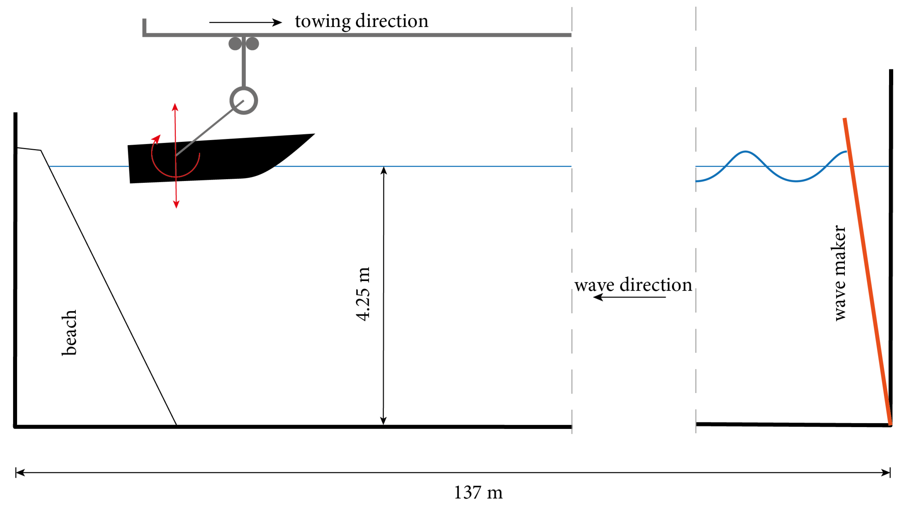
Figure 1. Scheme of the experimental setup.
Jmse 11 00700 g001
Figure 2. Absolute and relative reference systems to describe wave propagation over a steady current.
Jmse 11 00700 g002
Figure 3. Numerical wave flume implemented in DualSPHysics with details of the principal features.
Jmse 11 00700 g003
Figure 4. Free roll decay test performed in DualSPHysics: sketch of the numerical modeling (a) and comparison between experimental and numerical roll amplitudes with different SPH resolutions (b).
Jmse 11 00700 g004
Figure 5. Free-surface elevation for three wave conditions in presence of steady current.
Jmse 11 00700 g005
Figure 6. Experimental and numerical hull motions (heave and pitch) for 3 of the evaluated wave patterns.
Jmse 11 00700 g006
Figure 7. Response Amplitude Operator (RAO) for heave (a) and pitch (b) motion for the investigated cases.
Jmse 11 00700 g007
Figure 8. Velocity field of the incoming waves and current and pressure distribution under the hull’s keel in different phases of the hull motion in wave for Case 4 of Table 2.
Jmse 11 00700 g008
Table 1. Dimension of the C2s hull model.
DimensionsUnitC2s Hull
Length overall L O A [m]1.567
Length waterline L W L [m]1.440
BeamB[m]0.435
Beam waterline B W L [m]0.396
Longitudinal CG position L C G / L W L [-]0.394
Vertical CG position V C G / B W L [-]0.501
Massm[kg]20.91
Roll gyradius k x x [m]0.52
Pitch gyradius k y y [m]2.79
Table 2. Simulated wave conditions (deep water waves) as reproduced in the experimental facility; the colored dot represents the cases shown in the following charts.
CaseAngular Frequency
ω GEN [rad/s]
Wavenumber
κ [1/m]
Relative Wavelength
λ / L WL [-]
Amplitude
H [m]
Wave Steepness
ε = κ ( H / 2 ) [-]
Water Depth
d [m]
1 Jmse 11 00700 i0013.4561.2173.5850.10350.0634.25
2 Jmse 11 00700 i0023.7701.4493.0110.04400.032
3 Jmse 11 00700 i0034.0841.7002.5670.07410.063
4 Jmse 11 00700 i0045.0262.5751.6940.04890.052
5 Jmse 11 00700 i0056.2834.0241.0840.03130.063
Table 3. Correspondence between the input of the experimental and numerical model.
ExperimentalNumerical
Towing velocity U t Steady current U 0 U t
Generated frequency f G E N Encountered frequency f E N C = f G E N + U 0 / λ
Table 4. Response Amplitude Operator (RAO) percentage errors as reported in Figure 7.
λ / L WL
Exp
Δ z / ( H / 2 )
RAO Heave
STAR-CCM+
e STAR [%]

SPH
e SPH [%]

Exp
θ / ϵ
RAO Pitch
STAR-CCM+
e STAR [%]

SPH
e SPH [%]
3.58 Jmse 11 00700 i0011.18<1.0 2.5 1.15<1.05.2
3.01 Jmse 11 00700 i0021.25 6.4 12.8 1.17 11.1 11.1
2.57 Jmse 11 00700 i0031.1613.8 14.6 1.1015.4 16.4
1.69 Jmse 11 00700 i0040.5030.08.00.4926.56.1
1.08 Jmse 11 00700 i0050.18 11.1 11.1 0.12<1.0<1.0
Disclaimer/Publisher’s Note: The statements, opinions and data contained in all publications are solely those of the individual author(s) and contributor(s) and not of MDPI and/or the editor(s). MDPI and/or the editor(s) disclaim responsibility for any injury to people or property resulting from any ideas, methods, instructions or products referred to in the content.