Article

Numerical Study on the Breaking Process of the Seafloor Massive Sulfide Based on the FEM-SPH Adaptive Coupling Algorithm

1
State Key Laboratory of Ocean Engineering, Shanghai Jiao Tong University, Shanghai 200240, China
2
Yazhou Bay Institute of Deepsea SCI-TECH, Shanghai Jiao Tong University, Sanya 572024, China
3
School of Naval Architecture and Engineering, Jiangsu University of Science and Technology, Zhenjiang 212003, China
*
Author to whom correspondence should be addressed.
J. Mar. Sci. Eng. 2023, 11(4), 698; https://doi.org/10.3390/jmse11040698
Submission received: 21 February 2023 / Revised: 17 March 2023 / Accepted: 22 March 2023 / Published: 24 March 2023
(This article belongs to the Section Ocean Engineering)

Abstract

:
The research on seafloor massive sulfide (SMS) started relatively late, and the results on its breaking process are few. However, the breaking process contains evaluation indexes of safe, efficient and low-disturbance mining, so it is necessary to study the breaking process of seafloor massive sulfide. At the same time, the finite element method is used in most existing researches, and the system will automatically delete the failure element from the system during the simulation of rock-breaking, resulting in the inability to accurately obtain the chip state in the breaking process. In addition, SPH meshless method has unique advantages in dealing with large deformations of rock-breaking, but it has the problems of difficultly in boundary processing and serious computational time. In view of this, a hybrid discretization method of finite element method and smooth particle hydrodynamics (SPH) is proposed in this paper. On this basis, numerical simulation of a single-pick cutting seafloor massive sulfide based on the FEM-SPH adaptive coupling algorithm is carried out. Through the research in this paper, the regularity of the fragmentation process of polymetallic sulfides is obtained: firstly, the breaking process of seafloor massive sulfide experiences four stages: cutting-in of the pick, evolution of the high-stress zone, formation of the dense core, and the chips’ splash. Secondly, the three-dimensional forces on the pick change in fluctuation in the cutting process. Thirdly, the stress wave propagation is unbalanced and biased in the cutting process. Fourthly, the chips’ splash mainly has three directions: jet flow towards the opposite direction of the cutter cutting, spluttering perpendicular to the cutting surface of the pick, and sliding along the cutting surface. Finally, the chip mass is positively correlated with the cutting time. In this paper, a simulation framework for rock-breaking is proposed, and its advantages have been effectively verified.

1. Introduction

In recent years, strategic mineral resources have increasingly played an irreplaceable role in emerging industries such as new materials, new energy, aerospace, and defense industries [1]. With the vigorous development of new industries, the shortage of strategic mineral resources on land is becoming increasingly serious. As a new frontier of strategic resource reserves, the deep sea contains many kinds of mineral resources with commercial development prospects, including polymetallic nodules, cobalt-rich crusts, and seafloor massive sulfide (SMS), and is rich in strategic mineral resources such as copper, nickel, cobalt, manganese, barium, and selenium. The research of the first two minerals started earlier, and a relatively complete mining theory has been formed. However, the theoretical research of SMS mining is still in the initial stage.
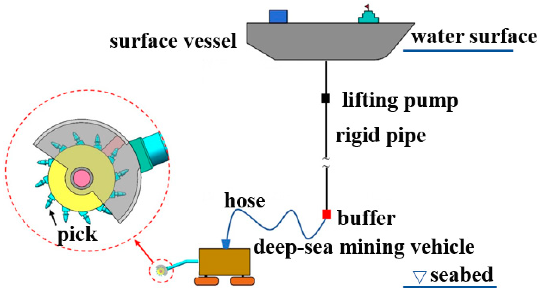
SMS occurs in relatively shallow waters and is considered as deep-sea mineral resources of great economic and commercial exploitation value. Most existing Deep-Sea Mining (DSM) systems includes a surface vessel, a rigid pipe, one or more lifting pumps, a buffer, a hose, and a deep-sea mining vehicle (DSMV) [2] as shown in Figure 1. The deep-sea mining vehicle is the core of the system. It mainly undertakes the work of rock-breaking and chips’ collection, and the chips’ collection mostly adopts the hydraulic collection scheme [3,4]. Nautilus Mining Company of Canada [5], JOGMEC of Japan [6,7], and 702 Research Institute of China State Shipbuilding Corporation Limited have successively developed SMS deep-sea mining vehicles. At present, the existing collecting heads of SMS mining vehicles all adopt spiral drum structures with cutting picks. It can be seen that the research on SMS mining can basically meet the engineering practice. At the same time, the research on the physical and mechanical properties of seafloor massive sulfide is the prerequisite for deep-sea mining. Physical and mechanical properties of model rock samples (obtained from Turkey) and seafloor core samples (obtained from Bismarck Sea) were tested in literature [8]. Meanwhile, the performance of reversing cutting polymetallic sulfide of spiral drum under different drum speed, traction speed, and center distance were studied in literature [9]. It is concluded that the counter-rotating drum cutter reduces cutting resistance. The authors in [10] used discrete element method (DEM) to simulate the cutting of seafloor massive sulfide by single pick and double picks, and analyzed the load characteristics of picks during cutting. Through this study, the trend of the cutting force in x, y, and z directions has been revealed. Moreover, the maximum resultant force on the cutting pick has been obtained. The authors in [11] established a mathematical model of the cutting force of a single-pick cutting seafloor massive sulfide. It is found that the fracture mode of seafloor massive sulfide under low confining pressure is mainly brittle failure. Balci conducted a study of the cuttability and drillability of rocks and obtained the relationship between drilling and cutting specific energies in atmospheric conditions [8]. Additionally, Balci estimated the specific cutting energy required for rock ore crushing under hydrostatic pressure. It was estimated that the rock crushing and cutting energy under hydrostatic pressure was 7.7–10.3 times that under land conditions [8]. To sum up, at present, more attention has been paid to the engineering practice of SMS mining, while the related basic theoretical research is rare. In order to meet the demand for safe, efficient, and low-disturbance commercial exploitation of deep-sea SMS, it is necessary to study the basic mechanism of the exploitation process. Moreover, the rock-breaking process of deep-sea mining consists of multiple single-pick rock-breaking instances, and single-pick is also the key to determine the breaking performance of the cutter head. Therefore, it is essential to establish a single-pick rock-breaking analysis model.
At present, in the study of cutting ore with a single pick, the authors in [12] studied the cutting force and specific energy consumption of a single pick when cutting carbonate.
It was found that the average values of specific cutting resistance and specific cutting energy consumption of the three rock types differ greatly. The cutting performance of picks in cutting extremely hard rock and conducting linear cutting tests on hard rock samples with a cutting machine were studied in literature [13]. The results show that larger cutting forces and energy consumptions are needed to break hard rock. In references [14,15], S. Qiao et al. explored the load characteristics of the spiral roller when breaking the cobalt-rich crust, and evaluated the prediction accuracy of the theoretical model of brittle materials. The results show that the peak cutting force predicted by the Evans model is closer to the experimental value at low pressure. Influence of rock strength parameters on rock cuttability was studied in a series of rock cutting tests which were carried out by a number of surveys [16,17,18]. Through these studies, the prediction model of the best cutting parameters was proposed when the pick cuts hard phosphate rock. The authors of [19] carried out the load characteristics of a conical pick in the process of cutting sandstone at different cutting angles. It has been found that the normal force linearly increases with increasing tip angle of the pick, and the ratio of normal to cutting force increases with increasing tip angle of the pick. In addition, the authors in [20,21,22] have also carried out related researches on rock-breaking by picks. Although there has been a lot of researches on the cutting of cobalt-rich crust, carbonate, and other rocks, there are few studies on the cutting of SMS. Considering that the density, compressive strength, and other physical and mechanical parameters of SMS are quite different from those of the rocks studied so far, therefore, it is necessary to carry out research on cutting SMS with picks. In addition, the research work is still mainly focused on the load characteristics, efficient breaking, and crack simulation at present, but little attention is paid to the basic problems involved in the cutting process, such as the chip state and the chip mass evaluation. However, these basic problems are the evaluation indexes of the feasibility, safety, efficiency, and low-disturbance mining of deep-sea mining. In particular, the chips generated in the crushing process, some of which are small particles, suspended and settled in the marine environment, are an important source of the formation of plume. The generation of plume worsens the marine environment and destroys marine biodiversity, and the impact is long-term. The mass and state of chips are related to the intensity and scale of plume flow. As low-disturbance mining has become the threshold of deep-sea mining, more and more attention has been paid to the impact of plume flow on the marine environment. Therefore, it is urgent to carry out scientific research on these basic problems.
Numerical simulation is an effective method to study rock-breaking by cutting tools. However, the system will directly delete the elements that reach the failure threshold with finite element method (FEM). This numerical method of element deletion not only causes material loss, but also does not conform to the actual physical process. In particular, FEM method has obvious disadvantages when carrying out research on the formation of chips by breaking. In recent years, a method of automatically transforming the failure element into a smoothed particle hydrodynamics (SPH) has become a research hotspot. This algorithm, namely FEM-SPH adaptive coupling algorithm, can convert the elements that reach the failure threshold into SPH particles, which can make up for the defects of single FEM method in numerical calculation. The determination of the transformation mechanism of the algorithm depends on the selection of the threshold. An algorithm was developed to determine the damage in literature [23] which can determine the location of the crack point.
Considering that the generation of chips is the result of element failure and detachment from the body, this paper takes element failure as the threshold of transformation. FEM-SPH adaptive coupling algorithm has been widely used in many fields. Among them, the authors in [24,25] have carried out the study of fluid–solid interaction with large deformation using the FEM-SPH adaptive coupling algorithm. The FEM-SPH adaptive coupling algorithm is used to simulate the high-speed collision process (involving the mutual collision process of bullets hitting the target plate, birds hitting aircraft, etc.) by a number of surveys [26,27,28]. In references [29,30], the authors used the FEM-SPH adaptive coupling algorithm to carry out the numerical simulation of the blasting process. Nan Xiao used FEM-SPH adaptive coupling algorithm to simulate the breaking process of TBM rolled rock [31]. To sum up, FEM-SPH adaptive coupling algorithm is mostly used in the field of explosion and high-speed impact, but rarely used in the research of rock-breaking. Considering that the finite element method is difficult to observe the chip state when simulating rock-breaking, the FEM-SPH adaptive coupling algorithm is considered to be applied to the numerical simulation of cutting SMS by picks.
Analyzing the above, there is still a lack of relevant theoretical research on the process of rock-breaking for seafloor massive sulfide, so it is necessary to carry out relevant research work. Moreover, the FEM cannot simulate the characteristics of chips, so it is urgent to find a high fitness simulation method. Considering that the SPH meshless method has unique advantages in dealing with large deformation problems of rock-breaking, but has the problems of difficult boundary processing and serious computational time, therefore, the finite element method (FEM) and smoothed particle hydrodynamics method (SPH) are combined to form an effective calculation framework to simulate the nonlinear dynamic process of cutting SMS with a single pick in this paper. According to the simulation results, based on the feasibility, safety, efficiency, and low-disturbance environmental protection factors of deep-sea mining, the breaking process of seafloor massive sulfide is studied and analyzed from five aspects: breaking process, load characteristics, stress response characteristics, chip state, and chip mass evaluation. Finally, the superiority of the FEM-SPH adaptive coupling algorithm in numerical simulation of the rock-breaking process is further demonstrated by comparing it with the FEM method. This research provides a new perspective for the prediction of environmental pollution scale of deep-sea mining.

2. Basic Theory

2.1. FEM-SPH Adaptive Coupling Algorithm

When the finite element method based on Lagrange is used to simulate rock-breaking, the system will automatically delete the elements that have reached the failure criterion, which not only leads to partial energy non-conservation, but also cannot effectively observe the phenomenon of chip splashes. Therefore, the FEM-SPH adaptive coupling algorithm is considered in the process of cutting the SMS by pick, and the FEM-SPH is updated according to the failure of elements. That is, when the rock is broken to produce chips, the failure elements are automatically converted into SPH particles. The adaptive coupling process of FEM-SPH is shown in Figure 2. At the same time, SPH algorithm, finite element-particle coupling algorithm, and finite element-particle contact algorithm are used to update the stress, strain, damage, and other parameters of the converted particle elements.
The converted SPH particle is consistent with the corresponding nodes of the failure element in parameters such as mass, position, velocity, and stress. The particle velocity is calculated from the momentum of the original element, and the length of the smooth particle is obtained from the conservation of mass of the element:
L = ( 1 N e ) i N e r 0 i ( ρ 0 i ρ i ) 1 / 3
where: L is the length of the smooth particle; N e is the number of elements associated with the particle; r 0 is the initial element size, ρ 0 and ρ represent the initial density and the current density, respectively [32].
The basic principle of finite element-particle contact algorithm is: firstly, all the major surfaces that may contact with each SPH particle are determined. Then, each SPH particle is detected through penetration to determine whether the particle is in contact with the element, and each particle and a principal surface or principal surface node form a contact pair. For each contact pair, according to the conservation of linear momentum and angular momentum, the normal velocity and position of the particle and the main surface node are adjusted to eliminate the particle’s penetration into the main surface. The change of normal velocity of the smooth particle and main surface nodes is as follows:
Δ v s = α ( δ / Δ t ) / [ 1 + i = 1 j ( R i 2 m s / m i ) ]
Δ v i = R i m s Δ v / m i
where: Δ v s and Δ v i are the velocity increment of the particle point i and the n iteration of the node on the main surface of the element, respectively; j is the total number of major nodes; m s and m i are the mass of the particle point and the node of the main surface of the i element, respectively; R i is the proportion of the momentum transferred from the particle point to the i node of the main surface of the element; δ is the penetration distance of the particles in the n 1 iteration; Δ t is the iteration time step, and α is the ratio of speed and position change [33]. During each iteration:
α = 1 / n N + 1
where: N is the total number of iterations and n is the current iteration number. When n = N , α = 1 [32,33,34].
The finite element-particle coupling algorithm means that particles are bonded on the surface of the element. According to the moving distance of particles in the surface and the principle of momentum conservation, the velocity variation formula of particles and nodes in the plane similar to the contact algorithm is established:
Δ u s = α ( δ ¯ / Δ t ) / [ 1 + i = 1 j ( R i 2 m s / m i ) ]
Δ u i = R i m s Δ v s / m i
where: δ ¯ is the moving distance, and u s and u i are the velocity increment of the particle point and the first i node on the main surface of the element, respectively. Other parameter values have the same meaning as above [32,33,34].
Based on the calculation above, the parameter values that need to be adjusted when the finite element is coupled with smooth particles can be obtained. The flow chart of FEM-SPH adaptive coupling calculation is shown in Figure 3.

2.2. Empirical Formula of Cutting Force

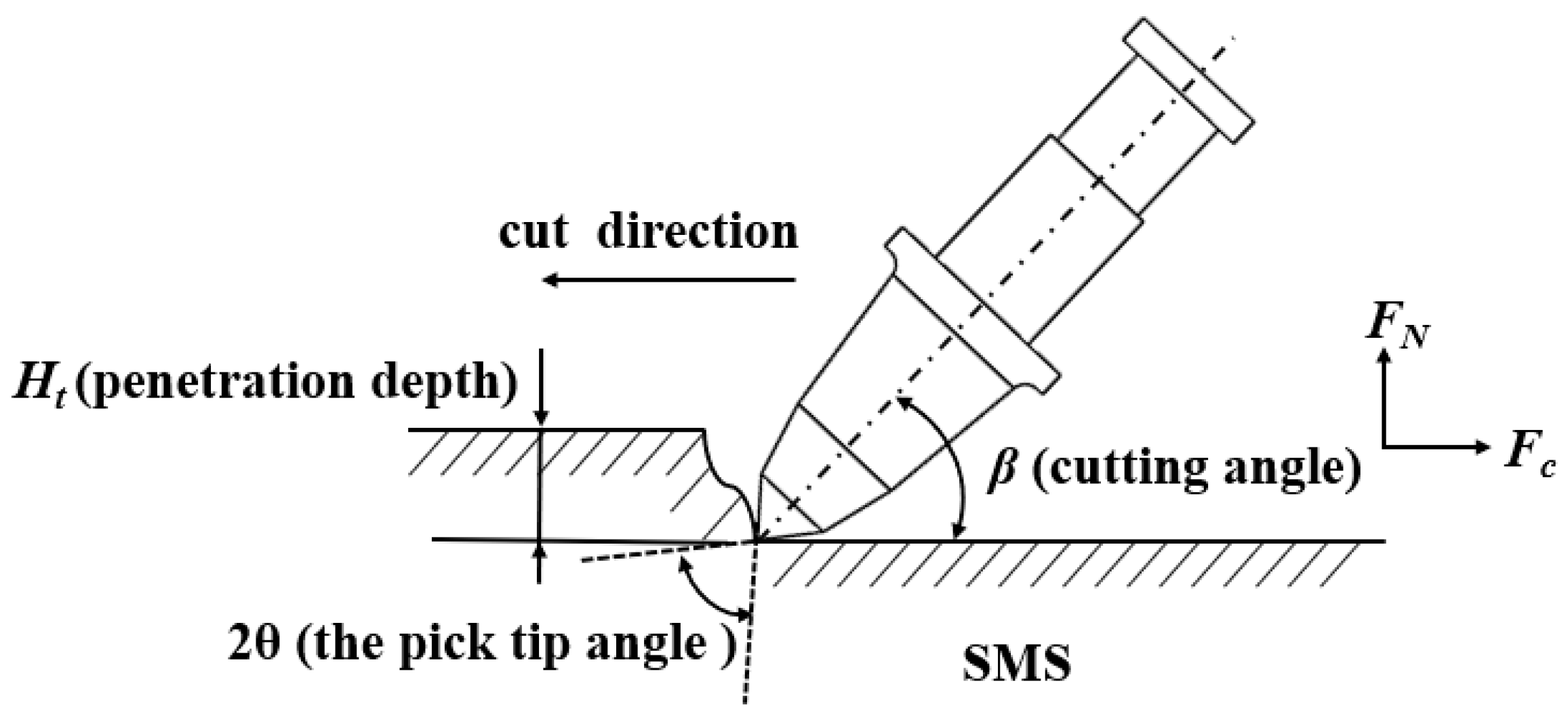
Figure 4 is a schematic diagram of cutting SMS with a single pick. Among these forces, the component force acting on the pick tip opposite to the cutting direction is defined as the cutting force, which is expressed by F C . The component force perpendicular to the cutting direction and deviating from the penetration direction is defined as the normal force, which is expressed by F N . The component perpendicular to the cutting path plane is defined as the lateral force, which is expressed by F S . At present, many scholars have carried out relevant research on the process of rock-cutting by pick, and put forward empirical formulas for predicting the peak cutting force. Considering the material properties of SMS and the geometry of the pick in the numerical simulation in Section 3, and that the impact of the seawater environment is not considered temporarily, on this basis, the empirical formulas applicable to this study mainly include:
① Evans prediction formula [35]
Evans proposed the calculation formula of peak cutting force of pick based on the tensile stress theory, and verified that the peak cutting force was significantly influenced by the compressive strength and tensile strength of rock:
F C = 16 π cos 2 θ ( σ t 2 σ c ) h t 2
where: F c is the peak cutting force of the pick; θ is the half angle of the pick tip; σ t is the tensile strength of SMS, taking 1.28 Mpa; σ c is the compressive strength of SMS, taking 10.38 Mpa [36,37], and h t is the penetration depth of the pick.
② Goktan prediction formula [38]
Goktan found that when there is no effective cutting, the Evans prediction formula is not zero. In view of this, a modified formula of peak cutting force is established based on the symmetrical cutting model:
F C = 4 π h t 2 σ t sin 2 ( θ + η ) cos ( θ + η )
where: η is the friction angle between the pick and the rock, and the recommended value is 8.5°. Other symbols have the same meanings as before.
③ Roxborough prediction formula [39]
Roxborough revised the Evans theoretical formula considering the influence of the friction angle between rock and pick on the peak cutting force:
F C = 16 π σ c h t 2 σ t [ 2 σ t + σ c cos 2 θ tan θ 1 + tan η ] 2
where: η * is the friction angle between the pick and the rock, with the range of 16 ° ~ 30 ° , and the recommended value is 16 ° . Other symbols have the same meanings as before.

3. Numerical Simulation

3.1. Numerical Model Establishment

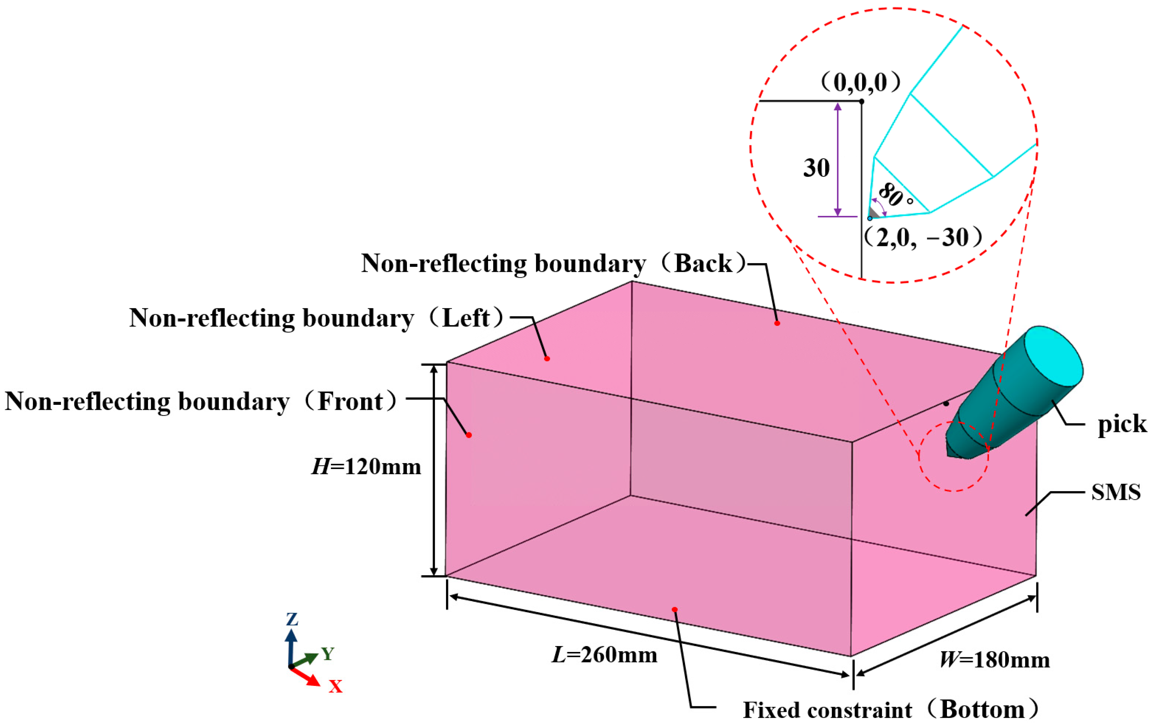
In this paper, LS-DYNA software platform, which has incomparable advantages in solving nonlinear dynamic problems, is used to carry out numerical simulation of the rock-breaking process. Figure 5 shows the numerical calculation model of cutting SMS with a single pick. In the calculation model, the coordinate system obeys the right-handed rule, the positive direction of the X-axis is the opposite direction of the cutting movement, and the positive direction of the Z-axis is the vertically upward direction. The mm-s-g system of units is used in the numerical simulation. The length of the calculation domain is determined by ensuring that there are three stable crushing cycles in the cutting process, and the width and height of the calculation domain are determined by ensuring the effective propagation of stress waves. After repeated iterations, the calculation domain in this paper is determined to be 260 mm × 180 mm × 120 mm (L × W × H). The bottom of the SMS is set as a fixed constraint [40,41,42], and the upper surface is a free surface. At the same time, the three circumferential surfaces are constrained as non-reflecting boundary conditions [40,41,42], so as to eliminate the expansion wave and shear wave that occur when the pick cuts the rock, and achieve the effect of simulating infinite cutting space. The penetration depth of the pick is 30 mm, and the cutting angle is 45°. At the initial moment, a certain position allowance is reserved between the pick and the SMS. SMS adopts the Holmquist–Johnson–Cook (HJC) constitutive model. The correctness of this constitutive model has been verified by simulation in reference [11], and the specific parameters of the constitutive model are shown in Table 1 [11]. In the numerical simulation process, the pick is idealized as a rigid body without considering pick wear. At the same time, the movement direction and rotation of the rigid body are constrained, and only the degree of freedom of the rigid body moving in the X direction is reserved. The cutting speed of numerical simulation is determined by comprehensively considering the structural dimensions of the Nautilus mining vehicle (spiral drum diameter 1300 mm, rotating speed 35 r/min) and the economic requirements of commercial mining. After final confirmation, the real mining process is simulated by giving the cutting speed of 3000 mm/s along the negative direction of the X-axis of the pick. Erosion_Surface_to_Surface contact algorithm is used between pick and SMS to ensure that the unfailed rock unit can still contact the cutter after the rock material unit that meets the failure criterion is damaged by cutting [43]. FEM-SPH adaptive coupling algorithm is adopted in the cutting process, and the element failure is taken as the criterion for the finite element mesh element to be converted into SPH particles. The numerical simulation time is 0.05 s, and the sampling interval is 1 × 10⁻⁴ s. In the process of numerical simulation, the seawater environment, the suction of chips, and the influence of turbidity limitation equipment are not considered temporarily.

3.2. Mesh Division and Time Step Determination

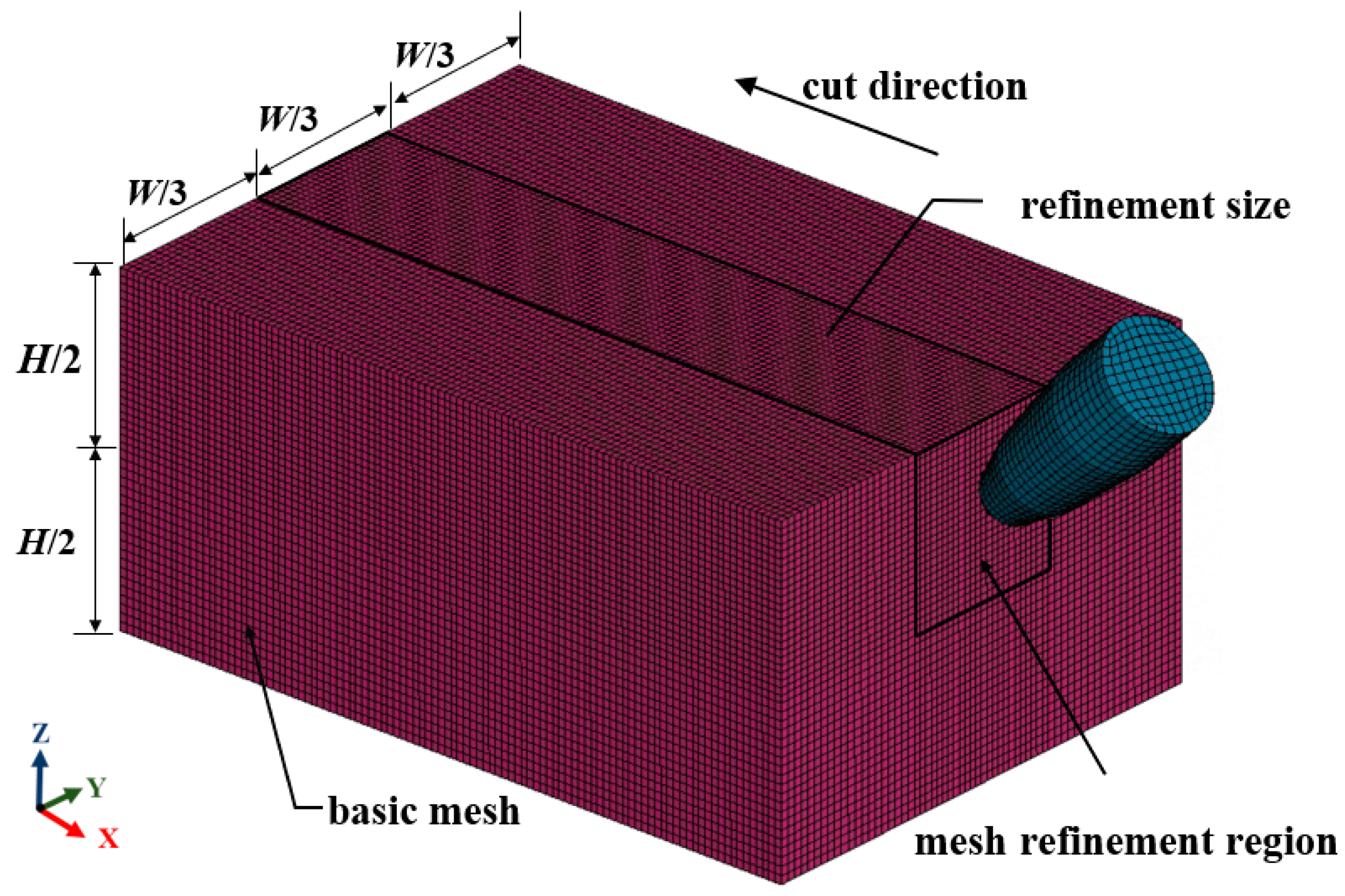
Mesh division is the core of numerical simulation. Considering the calculation accuracy and running time of dynamic problems, the hexahedral mesh generation scheme is adopted in this paper. Considering the energy dissipation characteristics of stress wave propagation in the cutting process of pick, the range of mesh refinement region is finally determined through repeated iterations. Finally, mesh independence verification is carried out by setting different mesh size models, and cutting force is taken as a reference index to determine the final mesh division scheme. The basic mesh size is 3 mm, and the refinement area mesh size is 2.5 mm. The model contains 296,692 elements and 311,715 nodes. The mesh has good orthogonality, and there are no concave meshes or distorted meshes. The mesh division is shown in Figure 6.
In the numerical simulation of cutting SMS with the single pick, the degree of time dispersion has a significant influence on the calculation efficiency and stability. The calculation formula of the numerical simulation stability time step is:
C d = E ρ S M S
Δ t = L e C d
where: C d is the expansion wave velocity of SMS; E is Young’s modulus of SMS; ρ S M S is the density of SMS; Δ t is the time step, and L e is the minimum characteristic element length [44,45].
Therefore, the numerical simulation stabilization time step is calculated to be 2 × 10⁻⁸ s, which is also consistent with the time step recommended by the system. However, the calculation is time-consuming with this time step. In view of the numerical research work that needs to be carried out in the later period, such as high-efficiency rock-breaking of the pick and optimization design of the spiral drum structure, it is necessary to carry out the exploration of using mass scaling in the numerical simulation of cutting SMS with a single pick to reduce the calculation time. There is a single mapping relationship between mass scaling and time step. Therefore, the exploration of mass scaling in this paper is also the exploration of the time step in numerical simulation. In this paper, a calculation set with four different time steps is designed to explore the influence of time steps on the numerical simulation results. During the comparison, in order to ensure the consistency of comparison parameters, the numerical calculation result at 2 × 10⁻⁸ s is taken as the standard value, the correctness of which has been verified by Section 3.3. Table 2 shows the comparison of calculation results with different time steps. Table 2 shows that the peak and mean cutting force first decreases and then increases, and the error of calculation results is relatively large. Especially when the time step size is 2 × 10⁻⁵, the peak value appears. This is because the time step size is too large, resulting in unstable contact between the pick and the SMS. Therefore, for the nonlinear dynamic process of SMS breaking, the use of mass scaling (increasing the time step) can save the calculation time, but it is easy to lead to contact instability, which makes the calculation result in a large error compared with the real value. Therefore, mass scaling is more suitable for static or quasi-static research, but it is not appropriate to use mass scaling (increasing time step) for numerical simulation of the nonlinear dynamic process of rock-breaking by cutting picks.

3.3. Numerical Method Calibration

In order to verify the feasibility of the numerical method in this paper, the accuracy of the numerical calculation method is analyzed. The results of numerical simulation in this paper are compared to those in reference [36], in which FEM method is used for numerical simulation. It is found that the time-domain variation trend of cutting force is highly consistent, and the error of peak cutting force is 18.2%. The reason for the error is that the peak cutting force is closely related to the sampling frequency, position allowance, numerical calculation time, numerical computation method, and other factors. In addition, considering the high dispersion of physical and mechanical parameters of SMS, the error of numerical simulation results in this paper are within an acceptable range. Meanwhile, the peak cutting force obtained by numerical simulation in this paper is compared with the current empirical prediction formula with high fitness, as shown in Table 3. Compared with the Evans prediction formula, Goktan prediction formula and Roxborough prediction formula, the error of peak cutting force is 3.5%, 2.02%, and 0.04% respectively, which is relatively small. Compared with the empirical formulas, which are obtained by experiments and have a certain range of reliable formulas, the error of the FEM-SPH adaptive coupling algorithm is small, mainly because the FEM-SPH adaptive coupling algorithm considers the chip state, and the numerical simulation using this algorithm is closer to the actual cutting situation. This is also the advantage of the FEM-SPH adaptive coupling algorithm in the calculation accuracy of numerical simulation. In addition, the ratio between the peak cutting force and the mean cutting force obtained by numerical simulation in this paper is 2.68, which also satisfies the theory of correlation between the peak cutting force and the mean cutting force by Goktan and N. Bilgin [38]. In conclusion, the calculation process and parameter configuration involved in the cutting of SMS in this paper are feasible.

4. Analysis of Numerical Simulation Results

According to the simulation results, based on the consideration of the feasibility, safety, efficiency, and green mining requirements of deep-sea mining, the breaking process of seafloor massive sulfide is studied and analyzed from five perspectives, including dynamic breaking process, load characteristics, stress response characteristics, chip state and chip mass assessment. Moreover, in the following study, the dynamic breaking of rock under the pick and the effective response of stress are taken as the evaluation factors of feasibility, the load characteristics are taken as the evaluation factors of system safety, the mass of chips is taken as the evaluation factors of efficient mining, and the effective prediction of chip mass and splash direction is taken as the evaluation factors of environmental protection.

4.1. Dynamic Breaking Process of SMS

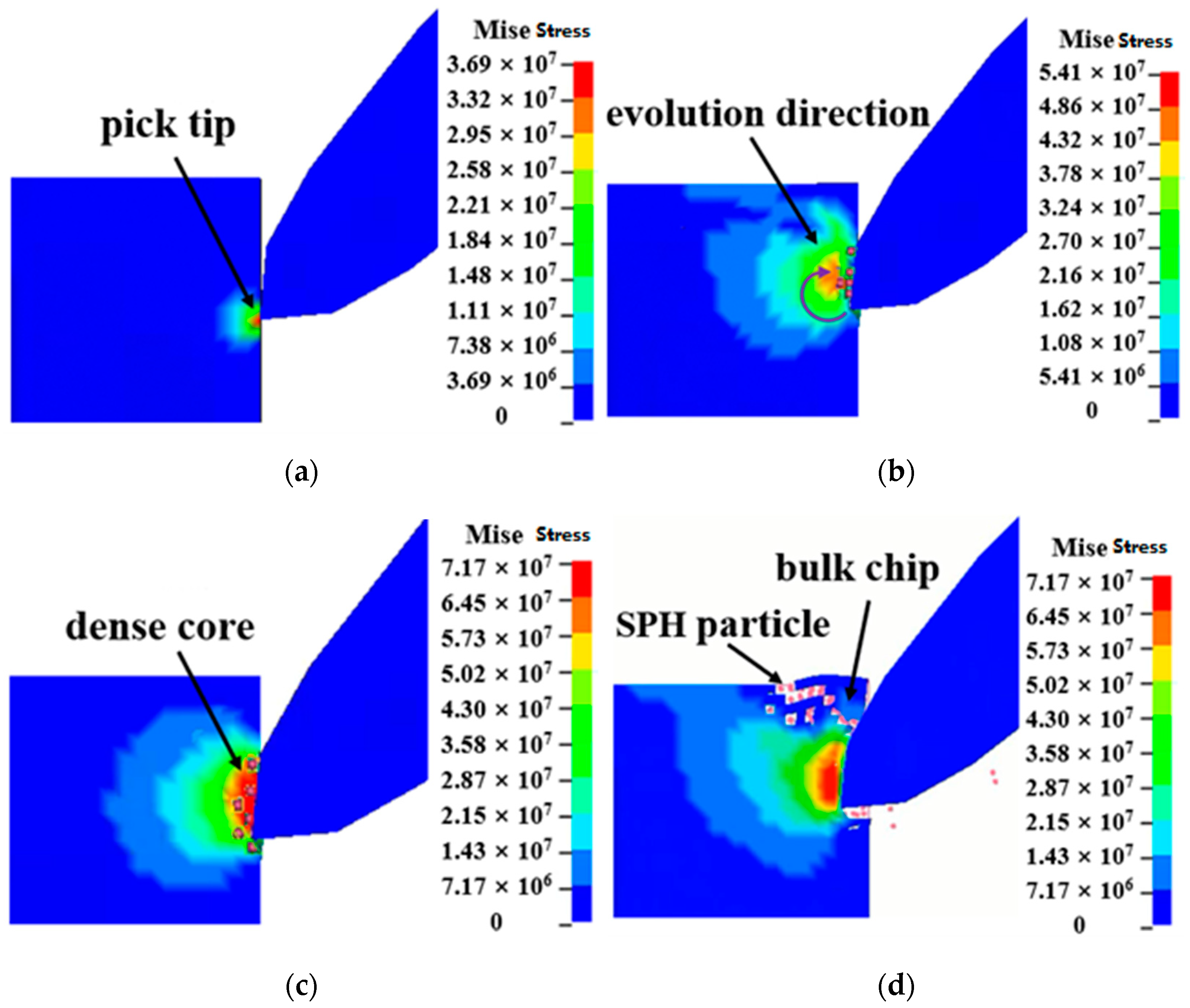
The dynamic breaking process is the premise of the feasibility and high-efficiency study of pick-breaking seafloor massive sulfide, and also the basic mechanism of deep-sea mining SMS which should be studied. Under the action of the pick, the seafloor massive sulfide can realize its separation from the rock body and constantly generate chips, which reflects the feasibility of the pick for deep-sea mining. As can be seen from Figure 7, in the initial cutting stage, the pick tip touches the seafloor massive sulfide, so there is a high-stress area near the pick tip. With the cutting of the pick, the contact area between the pick and SMS increases, and the stress spreads around and the high-stress area also shifts. With the cutting of SMS on the upper surface of the pick, the high-pressure area of the rock moves up to the upper surface of the pick. In addition, the SMS is squeezed by the pick and the dense core is produced in the high-stress area, and the energy is constantly accumulated, so that the range of the dense core is gradually increased. With the cutting of the pick, the SMS begins to crack. In this way, the chips are constantly separated from the seafloor massive sulfide’s body, resulting in new breaking pits. The dynamic crushing process of seafloor massive sulfide also reflects the feasibility of using picks for mineral mining. Therefore, the breaking process of SMS includes four stages: cutting-in of pick, evolution of high-stress zone, formation of dense core, and chip splashes. Additionally, its breaking process also tends to brittle failure, which is consistent with the research content in literature [46]. At the same time, according to the analysis of UCS (uniaxial compressive strength) and BTS (Brazilian tensile strength) ratio, its failure characteristics also conform to the laws in the literature [8]. Considering that this paper is a numerical simulation study of the cutting process of a single pick, the actual deep-sea mining involves a complex breaking process coupled with multiple picks. The number of picks required and the number of breaking heads required still need to be further evaluated which can use intelligent methods in the evaluation process [47,48].

4.2. Load Characteristics

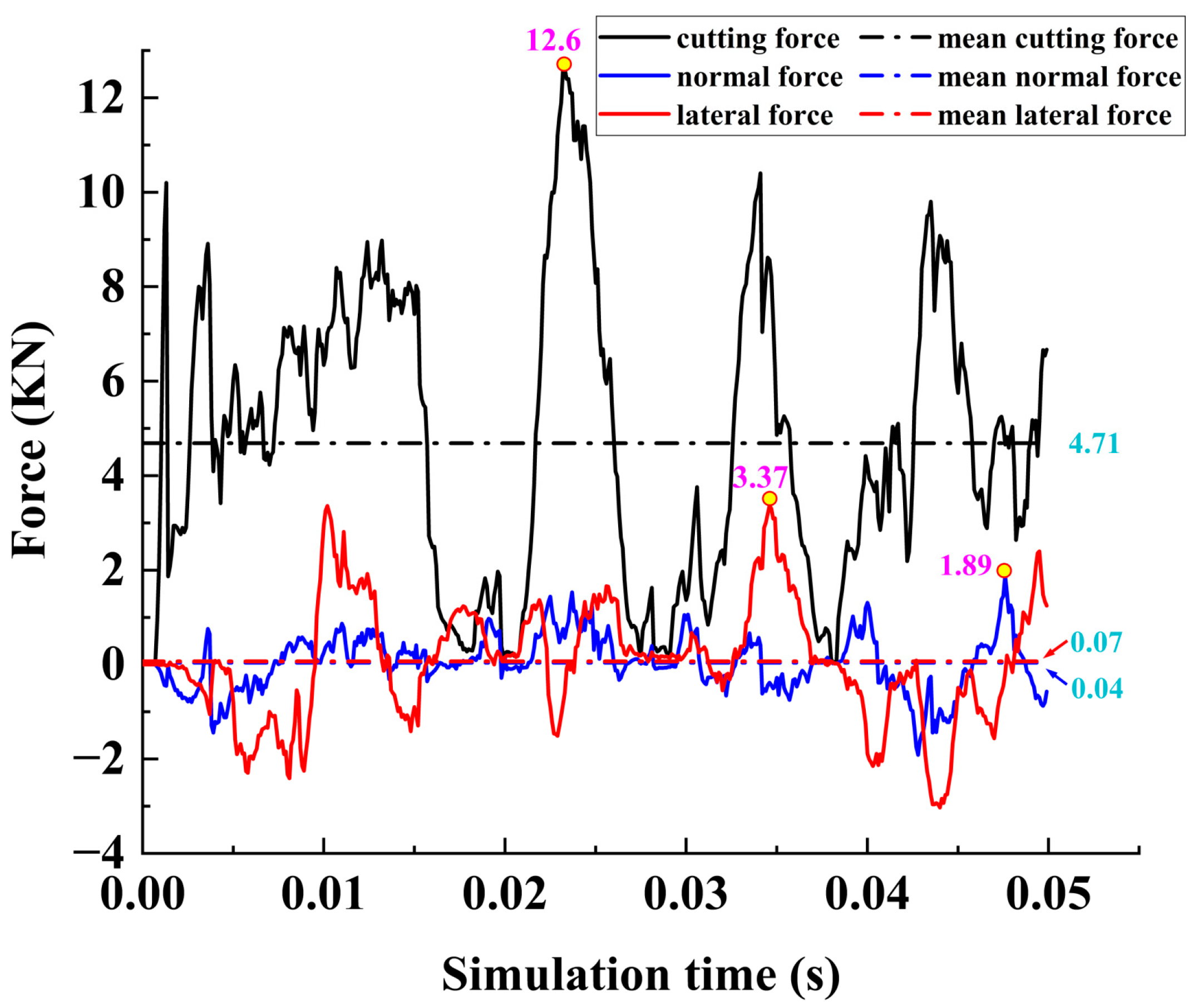
For safety considerations of the commercial exploitation of SMS, the load characteristics should be studied and evaluated. The mean, peak, and trend of the load in the breaking process affect the service life of the pick, and also affect the safety of the entire mining system. Therefore, it is necessary to study and analyze the load characteristics. It can be seen from Figure 8 that the cutting resistance changes in fluctuation in the cutting process. At the initial cutting stage, as the cutting pick intrudes into the SMS ore body, the cutting force of the pick is increasing constantly. With the increase of the contact area between the pick and SMS, the cutting force fluctuates violently at high frequency. In the stable cutting period, the contact area between the pick and SMS is basically constant, and the cutting force of the pick fluctuates periodically, with the mean cutting force as the reference axis. The amplitude of periodic fluctuation reaches the maximum at the moment of the SMS breaks. The fluctuation of the load also reflects that the breaking process of SMS conforms to the law of step-breakage of rock. In addition, both the normal and lateral forces are relatively small compared to the cutting force. Both of them always fluctuate repeatedly based on the zero position. The information on the load in the cutting process is shown in Table 4.

4.3. Stress Response Characteristics of the Elements

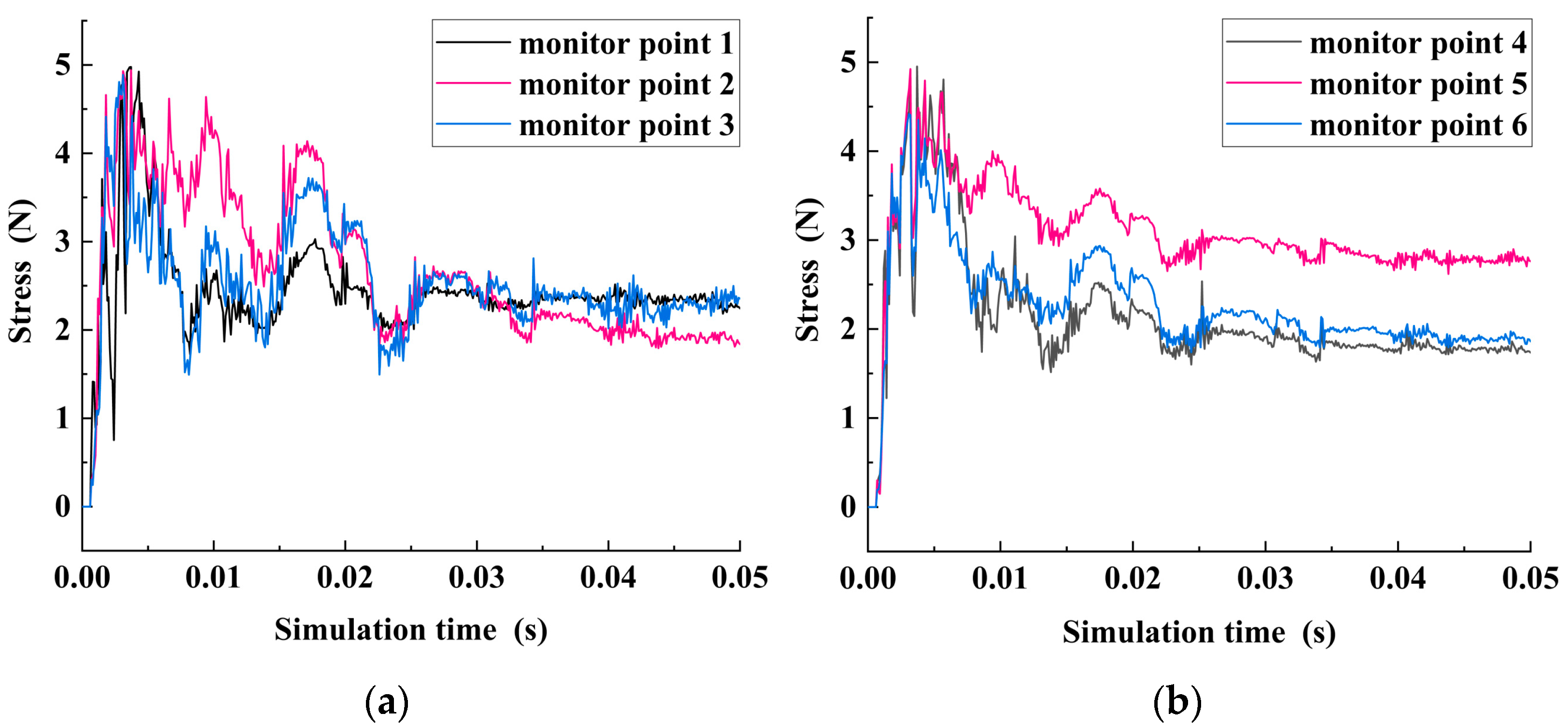
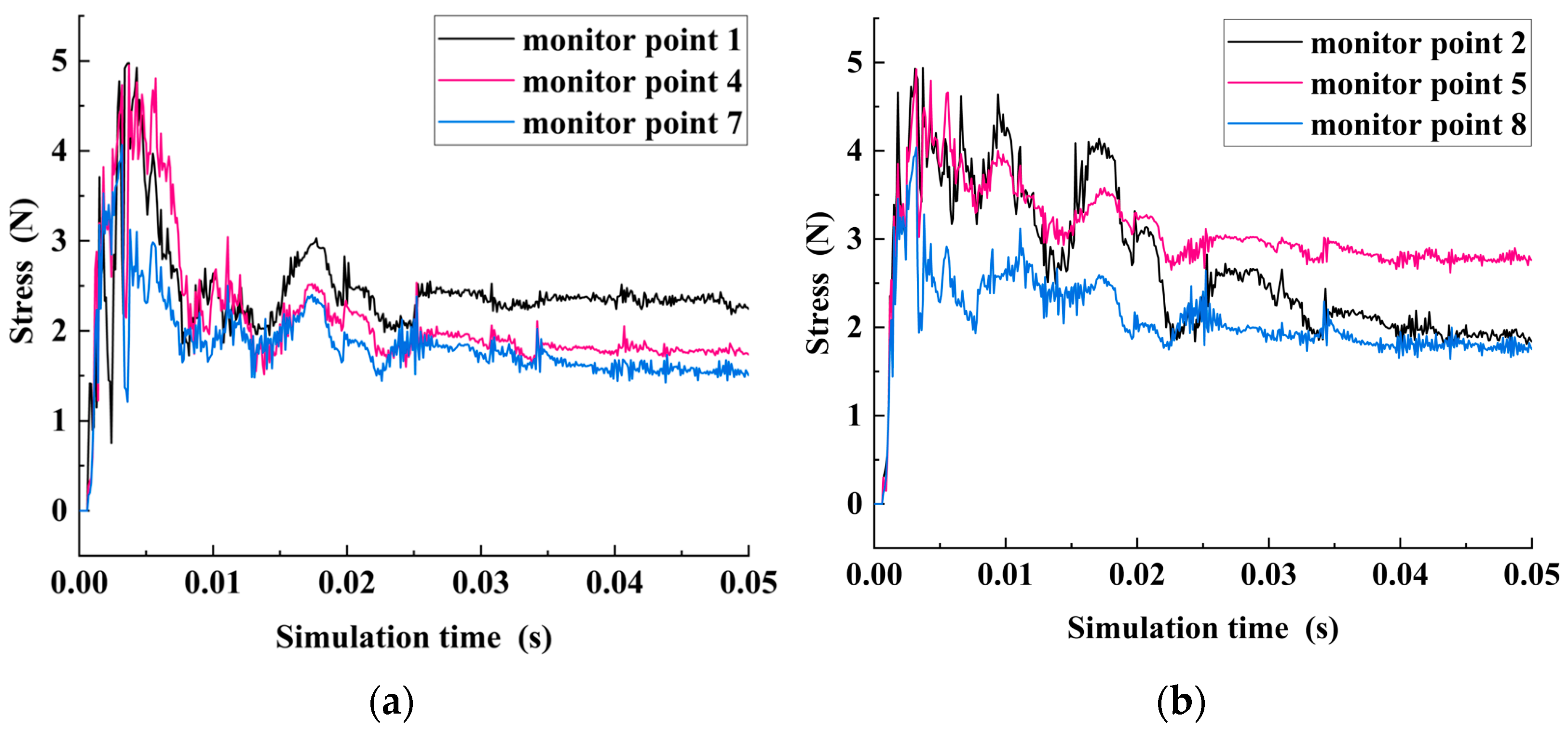
The study of stress characteristics in the breaking process is related to the feasibility of the pick-mining SMS and the optimization of structure size of ore collecting equipment. When the pick is used for breaking the seafloor massive sulfide, the effective response of stress reflects the feasibility of the breaking scheme. At the same time, according to the stress response characteristics, it is of great significance to guide the structural sizing of protective mining equipment and achieve efficient mining. In order to quantitatively study the stress variation rule of SMS, uniform sampling is conducted in the refinement area, and 9 typical units on the YOZ plane are selected as monitoring points, and their labels have been marked in Figure 9. The nine detection sites consist of two sets of lateral and two sets of longitudinal monitoring sites, labeled 1–8, and one monitoring site, labeled 9, is set in the horizontal direction of the contact point between the pick and the SMS.
As can be seen from Figure 10, the stress time-history variation trend of the lateral monitoring points is similar. In the initial cutting stage, with the continuous intrusion of the pick into the SMS ore body, the stress on SMS increases sharply, but the growth rate gradually decreases, and the stress peaks in a pulsating manner. Then the stress begins to decay, and keeps fluctuating up and down in a certain range, and the amplitude of the fluctuation gradually decreases. The stress transmission is felt almost simultaneously at the lateral monitoring points. Similarly, the time-history variation trend of stress at longitudinal monitoring points also has the same feature as shown in Figure 11. However, by comparing the data of six lateral and longitudinal monitoring points, it is found that the stress does not spread uniformly around the virtual center point of the pick tip. The stress peak value and stability value of monitoring points 2, 5, and 6 are larger than those of other monitoring points, indicating that the main direction of stress propagation in the right lower half plane is the oblique downward propagation direction with the cutting center as the origin, as shown in the predicted direction marked in Figure 9. At the same time, in the process of propagation, the stress is gradually decreasing. The main reason for the unbalanced stress propagation is that the coupling between the pick and SMD is a nonlinear process, which leads to the unbalanced local crushing of polymetallic sulfide, and thus causes the unbalanced stress.
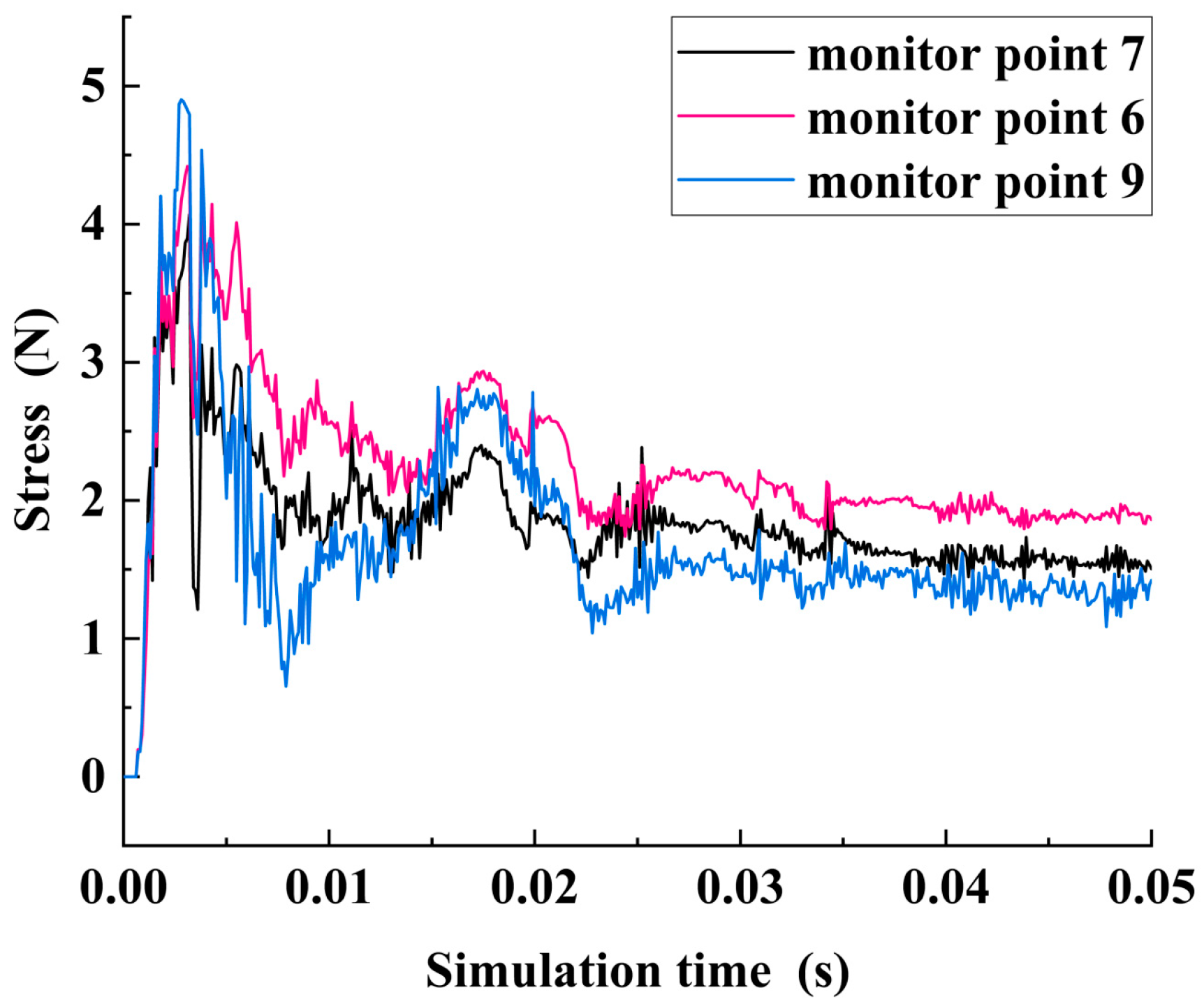
To verify the correctness of the main stress propagation direction in the right plane, the initial contact point between the pick tip and SMS is taken as the virtual center, and the virtual cutting circle is determined with R = 30 as the radius. In addition, elements numbered 7, 6, and 9 are taken as monitor points in the circumferential direction as shown in Figure 12. It is found that the peak stress and stable value of monitoring point 6 are slightly larger than those of monitoring points 7 and 9. Therefore, the imbalance and bias of stress propagation are proved again.

4.4. Analysis of Chip Generation and Splash Process

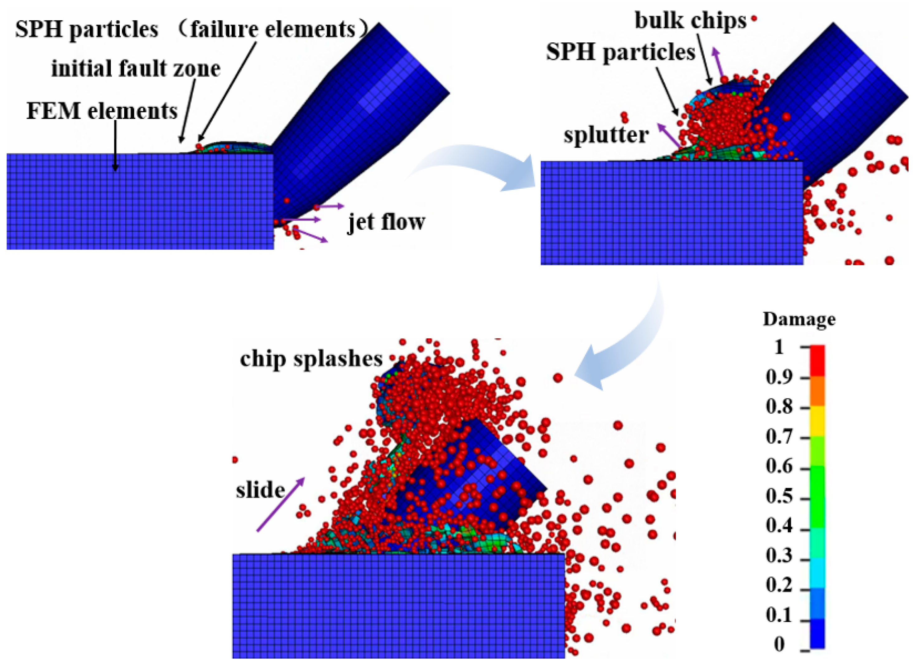
The study of the chips’ state during the breaking process is beneficial to guide the collection of chips, which is the basic mechanism of efficient collection of SMS and should be studied. Knowing the direction of the splashes can further guide the chip collection, so as to achieve efficient debris collection. Moreover, the chip is an important source of plume flow to the environment, which has a long-term effect. Therefore, the research of chip state is an indispensable part of low-disturbance mining in the deep sea. To avoid the chip from disappearing due to the contact between the chip and pick, the automatic node-to-surface contact between particles and the tool is added to better observe the generation and splash of chips. HJC constitutive model takes the accumulation of material damage as the criterion of failure. If the material damage accumulates to a value of 1, it will be regarded as material failure by the system. Figure 13 shows that, in the initial cutting stage, with the cutting of the pick, the SMS bulges upward under the combined action of extrusion and tension, resulting in a fault zone. At the edge of the fault zone, it can be seen that the failure finite element has been automatically transformed into SPH particles, and some chip particles jet from the gap between the pick and the seafloor massive sulfide to the opposite direction of the pick motion. With the continuous cutting of the pick, more and more SMS are broken, and these broken elements which reach the failure threshold are converted into SPH particles, which splash all around, and the direction of chip splashes are mainly perpendicular to the cutting surface of the pick. Although some elements failed to meet the failure criteria (D = 1), the ore bodies surrounding these elements were deleted because they met the failure criteria, so these elements were automatically separated from the SMS body, resulting in bulk SMS chips. As can be seen from Figure 13, after the pick is completely cut in, the generated chips tend to slide and spread upward along the curved surface of the pick because of its fast translation and cutting.
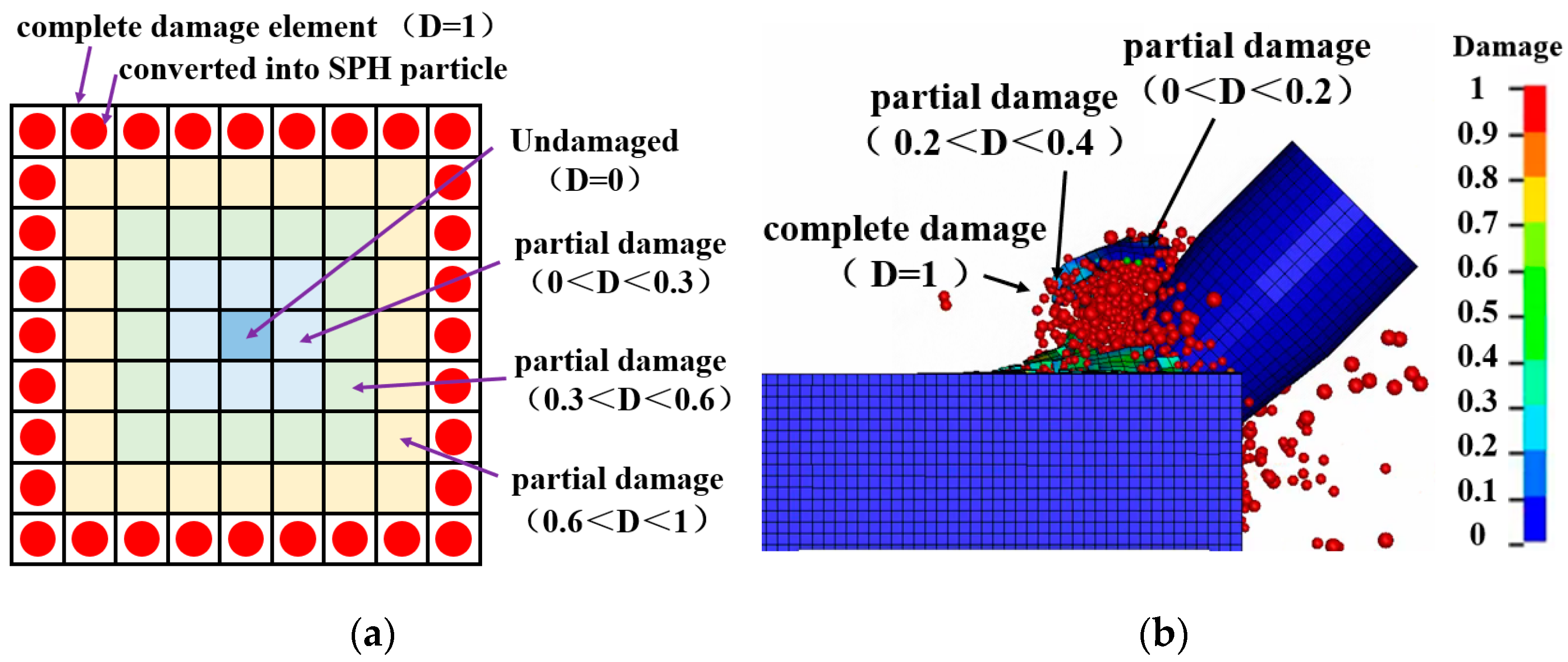
To explore the generation mechanism of bulk SMS chips and analyze the defects of finite element method in simulating chips, the damage of massive chips is analyzed in this paper. As shown in Figure 14, it is found that there is a completely damaged area around the bulk chip, and the closer it is to the chip center, the lower the damage value is. The finite element mesh element in the completely damaged area reached the failure threshold and was transformed into SPH particles. If the finite element method is used for numerical simulation only, this part of the element will be directly deleted by the system, and the state of this chip cutting cannot be observed. However, the occurrence of bulk chips is due to the damage and failure of the elements surrounding this part of the rock, which makes this part of SMS be forced to separate from the SMS body, thus forming bulk SMS chips. This is the chip that can be seen when the FEM is used to simulate.
In summary, the finite element method can only simulate the bulk chips (which are only part of the chip) that do not meet the failure criteria and are forced to fall off. The FEM-SPH adaptive coupling algorithm can simulate the state of all chips, including failure chips (this part of the chips are converted into SPH particles) that reach the failure criteria and bulk chips that fail to reach the failure criteria which are forced to fall off. The comparison between the results of chips at the same time observed by FEM and FEM-SPH numerical simulation is shown in Figure 15. Therefore, the FEM-SPH adaptive coupling algorithm has more significant advantages in the simulation of chips.

4.5. Chip Mass Prediction and Kerf Shape Analysis

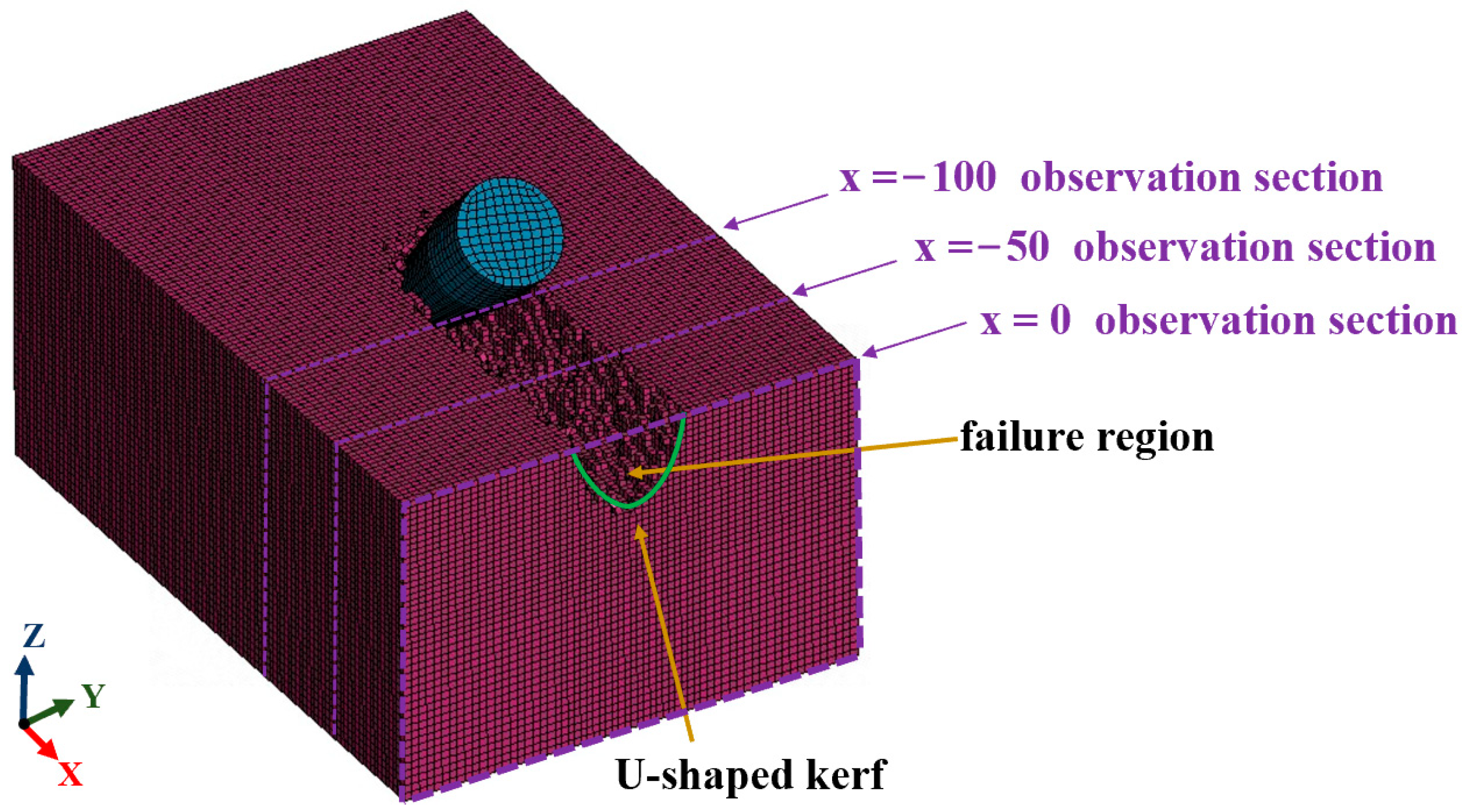
The chip quality in the breaking process is not only related to the economy of deep-sea mining, but also implies the elements of low-disturbance mining. Under the same evaluation index, the more mass of chips produced, the more efficient the mining, and the better the economy, which is also the index that needs be considered to achieve the commercial mining economy. At the same time, the prediction of high reliability of chip mass and timely adjustment of collection scheme according to the chip mass are also related to the low-disturbance mining of deep-sea mining and the environmental protection of the deep-sea mining process. It is the most important core index of deep-sea mining. At the same time, the research on breaking kerf is of great significance for optimizing the structure of ore-gathering equipment and realizing efficient mining. Figure 16 is the cutting result of the numerical simulation. It can be seen that the cutting failure elements are all in the refinement region, and the broken kerf is U-shaped. Figure 17 shows that the time-history curve (red solid line segment) of the volume of failure element increases with the fluctuation of cutting time. The blue straight line is the curve of the fitting relationship between the volume of the failure element and time in the stable cutting stage. Among them, the fitting degree index R2 = 0.99637, indicating that the fitting line well reflects the relationship between the volume of SMS broken by a single pick and cutting time.
Furthermore, the numerical simulation chip mass prediction formula of single-pick cutting SMS in this paper can be deduced as follows:
M = ρ S M S × 10 6 × ( 3.414 × t 0.7 )
where: M is the chip mass of SMS and ρ S M S is the density of SMS.
It can be seen that in the process of cutting SMS with the single pick, the chip mass (broken volume) has a linear relationship with cutting time. This formula can further guide the collection of chips. This paper is a preliminary exploration of the breaking process. The energy consumption, specific energy consumption, and operating parameters under the optimal specific energy consumption in the breaking process still need further exploration [8].
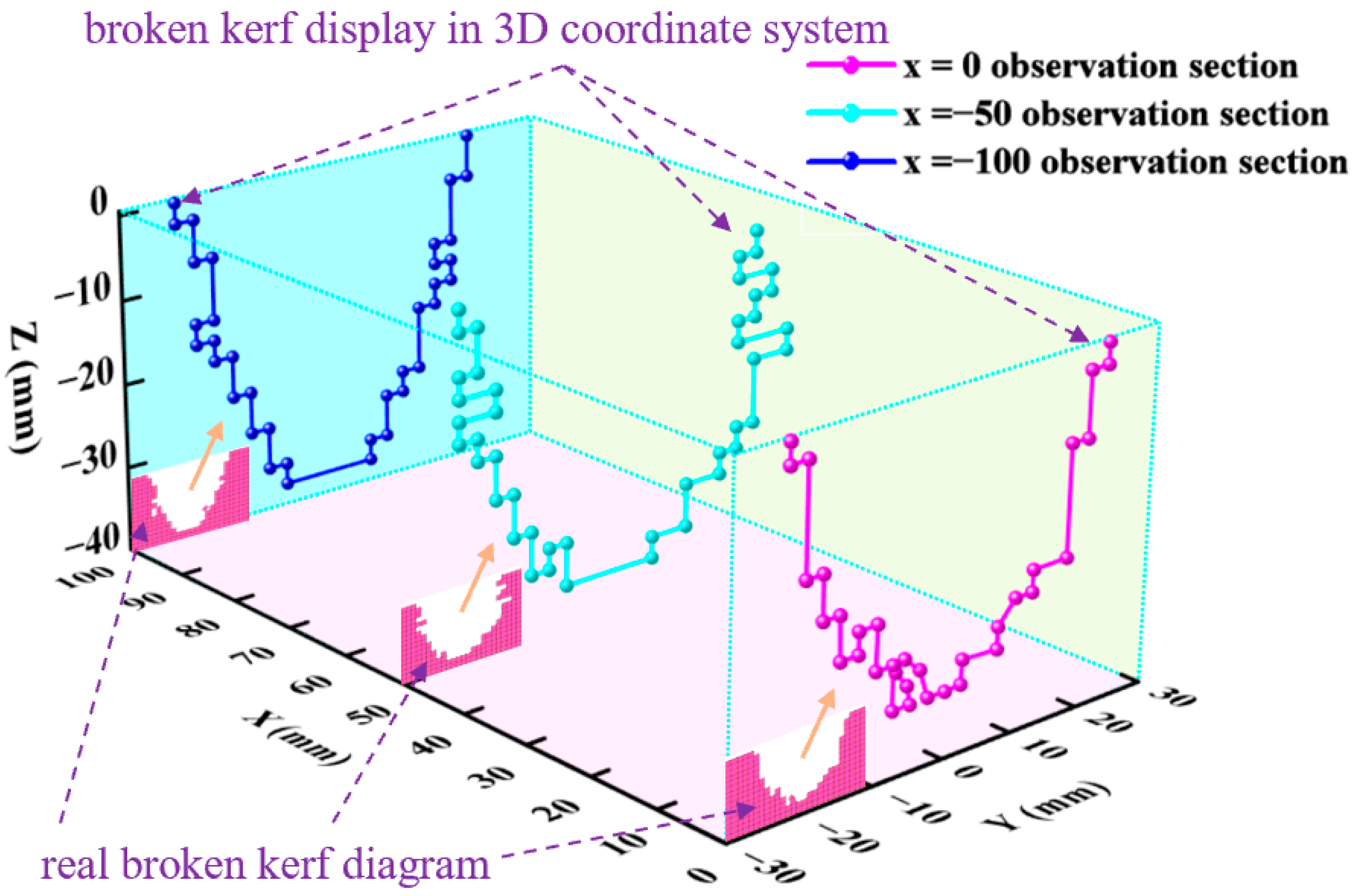
To observe the kerf shape of SMS cut by the single pick quantitatively and accurately, three typical observation sections are established with (1,0,0) as the normal vector: Observation plane 1: x = 0 observation section; Observation plane 2: x = −50 observation section; Observation plane 3: x = −100 observation section. The positions of three typical observation surfaces are shown in Figure 16. The real broken kerf is at the three observation surfaces (at the lower left corner of the three sections in Figure 18). In order to refine and quantify the observation, we draw the shape of the broken kerf in the three-dimensional coordinate system. It can be seen from Figure 18 that although there are local differences in the kerf shapes of the three sections, the overall kerf shapes are similar: the left and right sides are approximately symmetrical, and the opening near the free surface of SMS is large, and the downward opening gradually decreases. The depth of the kerf is slightly greater than the penetration depth of the pick, and the kerf shapes are all U-shaped. This also justifies the rationality of the trend of increasing volatility of the time-history curve of broken volume from the side. At the same time, the approximate positive correlation between chip mass and cutting time is further proved, and the proposed prediction formula for the chip mass produced by cutting is qualitatively described. In addition, due to the non-equilibrium and bias of stress propagation, the width of the bottom of the cut kerf is obviously larger than the size around the tip of the pick, which is also the advantage of the pick with better rock-breaking efficiency than other rock-breaking tools.
To sum up, we have analyzed the dynamic breaking process and stress response characteristics of SMS, demonstrating the feasibility of using picks for deep-sea mining of SMS, and grasping the load characteristics in the cutting process, which is helpful for the safety evaluation of the mining system. We have also grasped the state of chips, which is conducive to the collection of chips and provides important support for the realization of low-disturbance mining in deep-sea mining. Moreover, the assessment of the mass of broken rock also provides data support for the realization of the commercial mining economy.

5. Comparison and Analysis of FEM-SPH Adaptive Coupling Algorithm and FEM Method

In this paper, the FEM-SPH adaptive coupling algorithm is used to numerically simulate the breaking process of seafloor massive sulfide. In order to better evaluate the superiority of this computing framework, a comparative analysis of the two algorithms is carried out based on the contents of Section 3 and Section 4. In addition, in order to quantify the calculation time, this paper uses a workstation to carry out a comparative study of numerical simulation, whose processor is Intel Core i5-E5-2680V2 and memory size is 64 GB. The results of numerical simulation show that the FEM method takes 46.7 h, and the calculation time using the FEM-SPH adaptive coupling algorithm is 99.7 h. Table 5 shows the qualitative assessment of the two numerical simulation methods in terms of rock breakage. It can be seen that although the FEM-SPH adaptive coupling algorithm sacrifices a certain amount of computing time, considering the popularity of high-performance computers and the feasibility of parallel computing, the gap in computing time of the two methods has become a weak factor to be considered. However, considering that the chip is a non-negligible factor in the load characteristics in the actual crushing process, the calculation accuracy of the FEM-SPH adaptive coupling algorithm is relatively high. Most importantly, FEM-SPH adaptive coupling algorithm has incomparable advantages in chip state simulation. In conclusion, FEM-SPH adaptive coupling algorithm has obvious advantages in numerical simulation of the rock-breaking process. At the same time, considering the unique advantages of FEM-SPH adaptive coupling algorithm in dealing with the chips, the chips generated by it presents two forms of reaching the failure threshold (SPH particle state) and not reaching the failure threshold (FEM form). Through the screening and control research of the proportion of the two chip forms, a solution is provided for efficient and low-disturbance ore mining.

6. Conclusions

This research focuses on the breaking process of seafloor massive sulfide, which was rarely studied before. In addition, different from the current literature, FEM-SPH adaptive coupling algorithm is used for this research in the numerical simulation of cutting SMS with a single pick for the first time. Through the research on the process of cutting SMS with the single pick, the following conclusions are drawn:
(1) The breaking process and crack evolution process of polymetallic sulfides are obtained. Among them, the breaking process of SMS includes four stages: cutting-in of cutting pick, evolution of high-stress zone, formation of dense core, and chip splash.
(2) The dependence between resistance and time is obtained. It is found that the cutting force, normal force, and lateral force suffered by the pick in the cutting process change in fluctuation, and the cutting force is the main force phase.
(3) The stress response characteristics are obtained. It is found that the stress wave propagation is unbalanced and biased during the cutting process of pick; the stress propagating in the lower right plane is inclined downward when the pick cuts SMS.
(4) The diffusion law of chips produced by crushing is obtained. It is found that the splash of chips generated by breaking is mainly in three directions: jet in the opposite direction of cutting by the pick; splash perpendicular to the cutting surface of the cutter, and slide along the cutting surface. At the same time, the excellent processing ability of FEM-SPH coupling algorithm in simulating rock-breaking has been well verified.
(5) The linear relationship between chip mass and simulation time is obtained. At the same time, it is also found that the cutting kerf of SMS with the single pick is U-shaped.
Through the research in this paper, it is found that the FEM-SPH adaptive coupling algorithm constitutes a potential calculation framework, which can be used for the numerical simulation of the rock-breaking process, especially for the research of rock-breaking particle splashing and particle size. In the next step, we will carry out the related research work of chip collection with high efficiency and low disturbance.
Author Contributions

B.Z.: Conceptualization; methodology; software; validation; formal analysis; resources; data curation; writing—original draft; writing—review and editing; supervision, project administration; funding acquisition. H.L.: Software; validation; formal analysis; data curation; writing—original draft; visualization. J.Y.: Methodology; software; validation; investigation; visualization; writing—review and editing. D.Z.: Software; validation; writing—review and editing. P.S.: Software; validation; writing—review and editing. S.L.: Software; validation; writing—review and editing. All authors have read and agreed to the published version of the manuscript.

Funding

This study was supported by the State Key Laboratory of Ocean Engineering. The authors are also grateful to Haining Lu for providing guidance on this study. This work was also supported by the Project of Sanya Yazhou Bay Science and Technology City (SCKJ-JYRC-2022-39), Science and Technology Committee of Shanghai Municipality (19DZ1207300).

Informed Consent Statement

Informed consent was obtained from all subjects involved in the study.

Data Availability Statement

Not applicable.

Acknowledgments

The authors would like to thank the anonymous reviewers for their constructive suggestions which comprehensively improved the quality of the paper.

Conflicts of Interest

The authors declare no conflict of interest.

References

  1. Gulley, A.L.; Nassar, N.T.; Xun, S. China, the United States, and competition for resources that enable emerging technologies. Proc. Natl. Acad. Sci. USA 2018, 115, 4111–4115. [Google Scholar] [CrossRef] [PubMed] [Green Version]
  2. Wu, Q.; Yang, J.; Guo, X.; Liu, L.; Lu, W.; Lu, H. Experimental study on dynamic responses of a deep-sea mining system. Ocean Eng. 2022, 248, 110675. [Google Scholar] [CrossRef]
  3. Kongar-Syuryun, C.; Aleksakhin, A.; Khayrutdinov, A.; Tyulyaeva, Y. Research of rheological characteristics of the mixture as a way to create a new backfill material with specified characteristics. Mater. Today Proc. 2021, 38, 2052–2054. [Google Scholar] [CrossRef]
  4. Adigamov, A.; Rybak, J.; Golovin, K.; Kopylov, A. Mechanization of stowing mix transportation, increasing its efficiency and quality of the created mass. Transp. Res. Procedia 2021, 57, 9–16. [Google Scholar] [CrossRef]
  5. Patel, B.N. Resource Mining and Law of the Sea: Evolving Issues and Challenges for the Indian State Practice. In Natural Resources and International Law–Developments and Challenges; Nomos Verlagsgesellschaft mbH & Co. KG: Baden-Baden, Germany, 2021; pp. 221–230. [Google Scholar]
  6. Ishiguro, S.; Masuda, M.; Komatsu, M.; Norihiro, Y.; Seiya, K. Development of the Pilot System for Test of Excavating and Ore lifting of Seafloor Polymetallic Sulfides. Mitsubishi Heavy Ind. Tech. Rev. 2018, 55, 1–7. [Google Scholar]
  7. Spagnoli, G.; Rongau, J.; Denegre, J.; Miedema, S.A.; Weixler, L. A novel mining approach for seafloor massive sulfide deposits. In Proceedings of the Offshore Technology Conference, Houston, TX, USA, 2–5 May 2016. [Google Scholar]
  8. Balci, C.; Copur, H.; Bilgin, N.; Ozdemir, L.; Jones, G.R. Cuttability and drillability studies towards predicting performance of mechanical miners excavating in hyperbaric conditions of deep seafloor mining. Int. J. Rock Mech. Min. Sci. 2020, 130, 104338. [Google Scholar] [CrossRef]
  9. Li, Y.; Li, M.-D.; Dai, H.; Liang, K.-S. Study on cutting-load characteristics of collecting cutter for seafloor massive sulfide. IEEE Access 2021, 9, 51925–51939. [Google Scholar] [CrossRef]
  10. Dai, Y.; Ma, F.; Zhu, X.; Liu, H.; Huang, Z.; Xie, Y. Mechanical tests and numerical simulations for mining seafloor massive sulfides. J. Mar. Sci. Eng. 2019, 7, 252. [Google Scholar] [CrossRef] [Green Version]
  11. Li, Y.; Wu, Q.; Lu, P. Study of material constitutive model of seafloor massive sulfide. Period. Ocean. Univ. China 2018, 48, 112–120. [Google Scholar]
  12. Andraş, A.; Popescu, F.D. Romanian Carbonate Rocks Cuttability Assessment Using Linear Cutting Tester. Min. Rev. 2021, 27, 50–56. [Google Scholar] [CrossRef]
  13. Jeong, H.; Cho, J.W.; Lee, S. Characteristics of cutting behavior of a pick cutter in hard rock. Adv. Struct. Eng. Mech. 2021, 8, 23–26. [Google Scholar]
  14. Qiao, S.; Qing, L.; Zhu, Z.; Wu, Y.; Li, Y.; Zhang, Z. Modelling and experimental investigation of cobalt-Rich crust cutting in ocean environment. Ocean. Eng. 2022, 245, 110511. [Google Scholar] [CrossRef]
  15. Qiao, S.; Zhang, Z.; Zhu, Z.; Zhang, K. Influence of cutting angle on mechanical properties of rock cutting by conical pick based on finite element analysis. Min. Sci. 2021, 28, 161–173. [Google Scholar] [CrossRef]
  16. Wang, S.; Sun, L.; Wang, S. Experimental investigation of multiple rock indentations on hard rock using a conical cutter at different cutting depths. IOP Conf. Ser. Earth Environ. Sci. 2021, 861, 042084. [Google Scholar] [CrossRef]
  17. Wang, S.-F.; Tang, Y.; Wang, S.-Y. Influence of brittleness and confining stress on rock cuttability based on rock indentation tests. J. Cent. South Univ. 2021, 28, 2786–2800. [Google Scholar] [CrossRef]
  18. Wang, S.-F.; Yu, T.; Li, X.-B.; Kun, D. Analyses and predictions of rock cuttabilities under different confining stresses and rock properties based on rock indentation tests by conical pick. Trans. Nonferrous Met. Soc. China 2021, 31, 1766–1783. [Google Scholar] [CrossRef]
  19. Wang, X.; Su, O.; Gao, K.-D. Evaluation of normal forces at varying cutting angles of conical picks on sandstones. Arab. J. Geosci. 2021, 14, 539. [Google Scholar] [CrossRef]
  20. Kawano, S.; Furuya, H. Mining and processing of seafloor massive sulfides: Experiences and challenges. Perspect. Deep. -Sea Min. Sustain. Technol. Environ. Policy Manag. 2022, 167–197. [Google Scholar] [CrossRef]
  21. Zhang, Q.; Fan, Q.; Gao, H.; Wu, Y.; Xu, F. A study on pick cutting properties with full-scale rotary cutting experiments and numerical simulations. PLoS ONE 2022, 17, e0266872. [Google Scholar] [CrossRef]
  22. Huang, D.; Wang, X.; Su, O.; Zheng, Z.-J.; Gao, M. Study on the cuttability characteristics of granites under conical picks by indentation tests. Bull. Eng. Geol. Environ. 2022, 81, 192. [Google Scholar] [CrossRef]
  23. Khayrutdinov, M.M.; Golik, V.I.; Aleksakhin, A.V.; Trushina, E.V.; Lazareva, N.V.; Aleksakhina, Y.V. Proposal of an Algorithm for Choice of a Development System for Operational and Environmental Safety in Mining. Resources 2022, 11, 88. [Google Scholar] [CrossRef]
  24. Khan, A.; Deb, D. An adaptive coupling of finite elements with smooth particle hydrodynamics particles for large deformation fluid–solid interactions. Comput. Math. Methods 2021, 3, e1137. [Google Scholar] [CrossRef]
  25. Hu, D.; Long, T.; Xiao, Y.; Han, X.; Gu, Y. Fluid–structure interaction analysis by coupled FE–SPH model based on a novel searching algorithm. Comput. Methods Appl. Mech. Eng. 2014, 276, 266–286. [Google Scholar] [CrossRef] [Green Version]
  26. Johnson, G.R. Numerical algorithms and material models for high-velocity impact computations. Int. J. Impact Eng. 2011, 38, 456–472. [Google Scholar] [CrossRef]
  27. Abdullah, N.A.; Yusoff, M.D.; Shahimi, S.-S.; Ahmad, M.I.M. Numerical modelling of bird strike on aerospace structures by means of coupling FE-SPH. Int. J. Integr. Eng. 2021, 13, 185–193. [Google Scholar]
  28. Wu, C.; He, Q.G.; Chen, X.; Zhang, C.; Shen, Z. Debris cloud structure and hazardous fragments distribution under hypervelocity yaw impact. Def. Technol. 2022. [Google Scholar] [CrossRef]
  29. Karmakar, S.; Shaw, A. Response of RC plates under blast loading using FEM-SPH coupled method. Eng. Fail. Anal. 2021, 125, 105409. [Google Scholar] [CrossRef]
  30. Yin, Z.Y.; Chen, X.W. Numerical study on the dynamic fracture of explosively driven cylindrical shells. Def. Technol. 2022. [Google Scholar] [CrossRef]
  31. Xiao, N.; Zhou, X.-P.; Gong, Q.-M. The modelling of rock breakage process by TBM rolling cutters using 3D FEM-SPH coupled method. Tunn. Undergr. Space Technol. 2017, 61, 90–103. [Google Scholar] [CrossRef]
  32. Sun, Z.; Zhu, T. Application of 3D FE-SPH adaptive coupling algorithm to penetration analysis of spaced multi-layered metallic targets. Explos. Shock. Waves 2015, 35, 416–422. [Google Scholar]
  33. Johnson, G.R.; Stryk, R.A. Conversion of 3D distorted elements into meshless particles during dynamic deformation. Int. J. Impact Eng. 2003, 28, 947–966. [Google Scholar] [CrossRef]
  34. De’an, H.; Chunhan, L.; Yihua, X.; Xu, H. Analysis of explosion in concrete by axisymmetric FE-SPH adaptive coupling method. Eng. Comput. 2014, 31, 758–774. [Google Scholar] [CrossRef]
  35. Evans, I. A theory of the basic mechanics of coal ploughing. In Mining Research; Elsevier: Amsterdam, The Netherlands, 1962; pp. 761–798. [Google Scholar]
  36. Li, Y.; Lu, F.; Liao, K. Dynamic analysis of cutting massive sulfide under high deepwater confining pressure. Ocean Eng. 2017, 35, 110–116. [Google Scholar]
  37. Dai, H.; Li, Y.; Li, M. Experimental Study on Failure Mechanical Properties of Two Kinds of Seafloor Massive Sulfides. Minerals 2021, 11, 1144. [Google Scholar] [CrossRef]
  38. Goktan, R. A suggested improvement on Evans’ cutting theory for conical bits. In Proceedings of the Fourth Symposium on Mine Mechanization Automation, Brisbane, Australia, 6–9 July 1997; Volume 1, pp. 57–61. [Google Scholar]
  39. Su, O.; Akcin, N.A. Numerical simulation of rock cutting using the discrete element method. Int. J. Rock Mech. Min. Sci. 2011, 48, 434–442. [Google Scholar] [CrossRef]
  40. Baranowski, P.; Kucewicz, M.; Pytlik, M.; Małachowski, J. Shock-induced fracture of dolomite rock in small-scale blast tests. J. Rock Mech. Geotech. Eng. 2022, 14, 1823–1835. [Google Scholar] [CrossRef]
  41. Liu, J.; Zheng, H.; Kuang, Y.; Xie, H.; Qin, C. 3D numerical simulation of rock cutting of an innovative non-planar face PDC cutter and experimental verification. Appl. Sci. 2019, 9, 4372. [Google Scholar] [CrossRef] [Green Version]
  42. Zhu, X.; He, L.; Liu, W.; Wang, S.; Luo, Y. The mechanism of particle impact-assisted rock cutting in hard brittle granite. Arab. J. Sci. Eng. 2022, 47, 11915–11928. [Google Scholar] [CrossRef]
  43. Zheng, J. Research on Arrangement of Pick Working Angle and Rock Breaking by Cutting Head Assisted with Water Jet. Master’s Thesis, China University of Mining and Technology, Xuzhou, China, 2015. [Google Scholar]
  44. Nicholson, P.; Cheng, X.; Lowet, G.; Boonen, S.; Davie, M.; Dequeker, J.; Van der Perre, G. Structural and material mechanical properties of human vertebral cancellous bone. Med. Eng. Phys. 1997, 19, 729–737. [Google Scholar] [CrossRef]
  45. Liu, Z.-F.; Zhang, J.-D.; Cheng, H.-B. Research on PCB collision based on ABAQUS/Explicit dynamic. China Mech. Eng. 2012, 23, 1456–1461. [Google Scholar]
  46. Yan, L.; Liang, Z.; Shaojun, L.; Dasheng, T. Breaking mechanism of massive sulfide under high deepwater confining pressure. J. Cent. South Univ. Sci. Technol. 2017, 48, 944–951. [Google Scholar]
  47. Afradi, F.; Ebrahimabadi, A.; Hallajian, T. Prediction of the number of consumed disc cutters of tunnel boring machine using intelligent methods. Min. Miner. Depos 2021, 15, 68–74. [Google Scholar] [CrossRef]
  48. Afradi, A.; Ebrahimabadi, A.; Hallajian, T. Prediction of the penetration rate and number of consumed disc cutters of tunnel boring machines (TBMs) using artificial neural network (ANN) and support vector machine (SVM)—Case study: Beheshtabad water conveyance tunnel in Iran. Asian J. Water Environ. Pollut. 2019, 16, 49–57. [Google Scholar] [CrossRef]
Figure 1. Deep-sea mining system.
Jmse 11 00698 g001
Figure 2. Schematic diagram of adaptive coupling of FEM-SPH.
Jmse 11 00698 g002
Figure 3. Calculation flow of FEM-SPH adaptive coupling algorithm [31]. Reproduced from [32], with permission from publisher EXPLOSION AND SHOCK WAVES, 2023.
Jmse 11 00698 g003
Figure 4. Schematic diagram of rock-cutting by pick.
Jmse 11 00698 g004
Figure 5. Numerical calculation model.
Jmse 11 00698 g005
Figure 6. Mesh division.
Jmse 11 00698 g006
Figure 7. Cloud map of fracture stress of SMS. (a) cutting-in of the pick tip. (b) evolution of high-stress zone. (c) dense core formation. (d) chip splashes.
Jmse 11 00698 g007
Figure 8. Load characteristic curve.
Jmse 11 00698 g008
Figure 9. Schematic diagram of monitoring point arrangement.
Jmse 11 00698 g009
Figure 10. Stress distribution of lateral monitoring points. (a) Monitoring data of the first group. (b) Monitoring data of the second group.
Jmse 11 00698 g010
Figure 11. Stress distribution of longitudinal monitoring points. (a) Monitoring data of the first group. (b) Monitoring data of the second group.
Jmse 11 00698 g011
Figure 12. Stress distribution of circumferential monitoring points.
Jmse 11 00698 g012
Figure 13. Chip generation and splash.
Jmse 11 00698 g013
Figure 14. Damage of bulk chips. (a) schematic diagram of bulk chips generation. (b) cloud diagram of bulk chips damage.
Jmse 11 00698 g014
Figure 15. Comparison of two different simulation methods. (a) FEM numerical simulation result. (b) FEM-SPH numerical simulation result.
Jmse 11 00698 g015
Figure 16. Simulation results of cutting failure.
Jmse 11 00698 g016
Figure 17. Time-history curve of the broken volume.
Jmse 11 00698 g017
Figure 18. Broken kerf of a typical section.
Jmse 11 00698 g018
Table 1. Parameters of HJC constitutive model for seafloor massive sulfide [11]. Reproduced from [11], with permission from publisher PERIODICAL OF OCEAN UNIVERSITY OF CHINA, 2023.
Parameter ρ ( t / m 3 ) G / G P a A B C N
Magnitude2.945.180.2241.880.0050.8
f c / M P a T / M P a ε 0 E F min S max P c r u s h / M P a P l o c k / G P a
10.241.9841 × 10−60.0173.417 × 10−4
μ l o c k D 1 D 2 K 1 / G P a K 2 / G P a K 3 / G P a
0.090.04185−171208
Note: ρ is the wet density of SMS; G is the shear modulus of SMS; A , B , C are the control coefficient of HJC yield surface; N is pressure hardening index; f c is the static compressive strength of SMS; T is the maximum tensile strength of SMS; ε 0 is the reference strain rate; E F min is the reference plastic strain; S max is the normalized maximum intensity; P c r u s h is breaking pressure; P l o c k is the compaction pressure; μ l o c k is compressive solid accumulated strain; D 1 , D 2 are the damage constant, and K 1 , K 2 , K 3 are the pressure constant [11].
Table 2. Comparison of calculation results with different time steps.
Time Step (s)Computing Time (h)Peak Cutting Force (KN)ErrorMean Cutting Force (KN)Error
2 × 10−899.71.26 × 10104.7 × 109
2 × 10−79.81.11 × 101011.91%3.04 × 10935.32%
2 × 10−61.21.11 × 101011.91%3.75 × 10920.21%
2 × 10−54.27.05 × 1010459.92%1.07 × 1010127.65%
Table 3. Comparison of numerical simulation results.
CategoryNumerical ResultsReference [36]
Results
Evans
Prediction Formula
Goktan
Prediction Formula
Roxborough
Prediction
Formula
Magnitude12.60 KN10.66 KN12.17 KN12.35 KN12.606 KN
Error18.20%3.5%2.02%0.04%
Table 4. Cutting load characteristics.
Force TypeCutting Force (KN)Normal Force (KN)Lateral Force (KN)
peak12.601.893.37
mean4.710.040.07
Table 5. Comparison between FEM-SPH adaptive coupling algorithm and FEM method.
ItemsFEM MethodFEM-SPH Adaptive
Coupling Algorithm
Calculation timeshort calculation timelong calculation time
Calculation accuracylarge errorsmall error
Breaking process revealsfeasiblefeasible
Chip assessmentbulk chipsall chips
Disclaimer/Publisher’s Note: The statements, opinions and data contained in all publications are solely those of the individual author(s) and contributor(s) and not of MDPI and/or the editor(s). MDPI and/or the editor(s) disclaim responsibility for any injury to people or property resulting from any ideas, methods, instructions or products referred to in the content.