Article

Design Equation of Buckle Propagation Pressure for Pipe-in-Pipe Systems

Centre for Marine Technology and Ocean Engineering (CENTEC), Instituto Superior Técnico, Universidade de Lisboa, 1049-001 Lisboa, Portugal
*
Author to whom correspondence should be addressed.
J. Mar. Sci. Eng. 2023, 11(3), 622; https://doi.org/10.3390/jmse11030622
Submission received: 2 February 2023 / Revised: 24 February 2023 / Accepted: 7 March 2023 / Published: 16 March 2023
(This article belongs to the Special Issue Subsea Pipelines)

Abstract

:
This paper focuses on the buckle propagation pressure of a pipe-in-pipe system under uniform external pressure. After the validation of the finite element model used in this research, several effects were studied. At first, the effects of the initial imperfection of the inner pipe, including the ovality and eccentricity, were checked out. Second, the influence of the scantling of the inner and outer pipes was tested. It was found that the dominant factor which affects the buckle propagation mode is changeable. Then, the boundary value of the above factor was investigated by varying the ratio of the outer and inner diameters. Finally, after a summary of the calculation results, an empirical formula was proposed to illustrate the relationship between the buckle propagation pressure and the geometrical parameters of the pipe-in-pipe system. Utilizing this formula, the buckle propagation pressure of the pipe-in-pipe system can be estimated rapidly with good accuracy.

1. Introduction

With the development of the offshore oil and gas industry, the deep-sea area becomes more and more important and valuable. As they constitute the main transmission unit, pipelines are required to be stronger to withstand higher water pressure. In an early work on the analytical solution of the collapse pressure of a single-walled pipe under external pressure, the significant influence of the ovality of the pipe cross-section was highlighted [1]. The pressure-carrying capacity is dependent on the D/t ratio of pipes under pure external pressure [2,3,4,5,6].
For subsea pipelines settled on the seabed with great water depth, thermal protection is still a task to be solved. Since the transmission distance of the pipeline system is up to several kilometres, the decrease in temperature will slow down the flow of the fluid, and even stop it. To avoid possible economic loss and environmental pollution in the aforementioned situation, pipe-in-pipe (PIP) systems are designed. The PIP contains two pipes: the outer pipe responsible for tolerating the hydrostatic pressure due to the subsea environment, and the inner pipe responsible for carrying the fluid gas or oil at high temperatures. Between the outer and inner pipes, the gap is expected to slow down the temperature dissipation of the fluid during the transmission over a long distance.
Alrsai et al. [7,8] figured out that the ultimate collapse strength of PIP is equal to that of a single-walled pipe with the same geometrical features as the outer pipe under external pressure. Generally, the two pipes of the PIP system are not very close to each other. Before the ultimate buckling state of the outer pipe, contact between the two pipes does not occur. Bhardwaj et al. [9] showed the uncertainty of the research of the PIP system.
In real engineering applications, the initial imperfection is always introduced onto the pipes during manufacture and installation procedures. When the pipes are subjected to external pressure, failure first occurs in the cross-section with the most severe initial imperfection, and then the buckle spreads rapidly along the axial direction [10]. Thus, in addition to the ultimate collapse strength of pipelines, the buckle propagation pressure (Pp) is considered another key characteristic.
In general, the buckle propagation pressure is lower than the ultimate collapse strength. It is worth determining the value of the buckle propagation pressure. Netto and Estefen [10] performed experimental tests on the buckle propagation of single-walled pipes. Then, the dynamic propagation phenomenon and the formation of flip-flop was introduced by Lee et al. [11].
Based on the proposed buckle deformation mode for single-walled pipes [12], the analytical solutions of Pp are derived. 
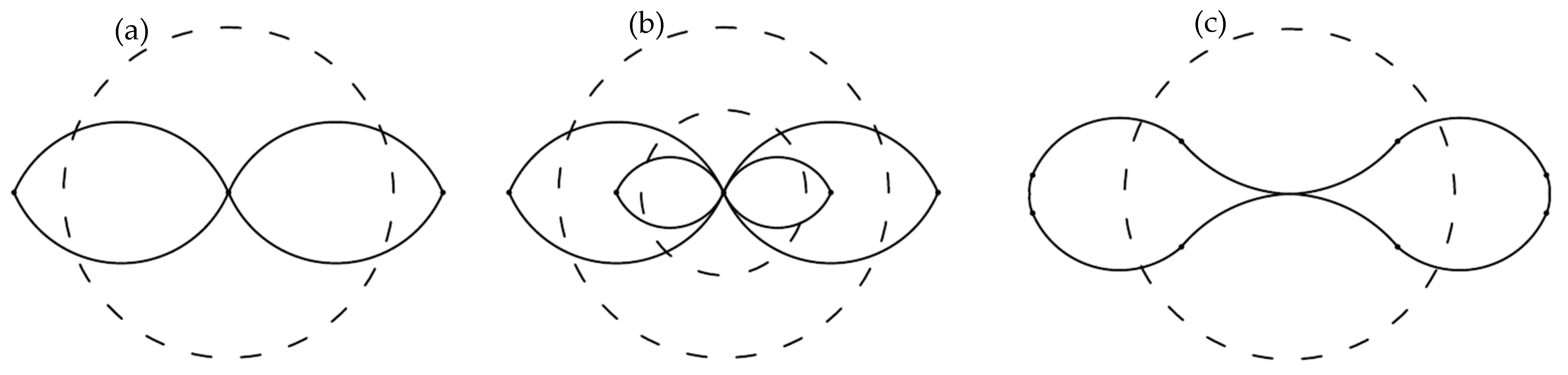
Figure 1 shows the buckle propagation mode of the pipeline in the 2D scenario. Based on that, Kyriakides and Vogler [13] investigated the buckle propagation phenomenon in the PIP system. The cross-section of the pipeline contains four plastic hinges for each pipe, as shown in Figure 1a,b.
The buckle propagation pressure of single-walled pipe proposed by Kyriakides et al. [12] is,
P Ps = 2 π 3 σ 0 t D 2
where, σ0 is the yield stress,
t is the thickness of the pipe,
D is the diameter of the pipe.
The buckle propagation pressure of PIP proposed by [13] is,
P P = 2 π 3 σ 0 t D 2 1 + σ 0 i σ 0 t i t 2
where, σ0i is the yield stress of the inner pipe,
ti is the thickness of the inner pipe.
Wierzbicki and Bhat [14] applied the balance of the internal and external energy in the derivation of the buckle propagation pressure. The internal energy is contributed to by eight plastic hinges as shown in Figure 1c. External energy is the work of the hydrostatic external pressure. The buckle propagation pressure is as follows:
P P 3 + 12 1 3 E σ 0 t D 0.7 σ 0 t D 2
where, E is Young’s modulus of the pipe.
Alrsai et al. [7] found two different buckle propagation modes in the numerical simulation of their study on a PIP system:
Mode A: The buckle propagation occurs after the contact between the upper and lower parts of the inner surface of the inner pipe;
Mode B: During buckle propagation, the inner surface of the inner pipe maintains a distance away from contact.
The difference between these two modes is illustrated in Figure 2. It was also concluded that the buckle propagation mode changes from Mode A to Mode B when the geometrical parameters satisfy the relationship of Do/to = 1.25Di/ti [7].
Similar phenomena were also illustrated by Gong and Li [15]. They classified buckle propagation into four modes, which could be also summarised into two modes according to the criteria of Mode A and B from [7]. The research investigated the buckle propagation pressure experimentally and numerically, while empirical equations were derived.
In the previous research, the dominant factor influencing the buckle propagation mode is assumed to have a constant value. Moreover, in the parameter studies, the variables are considered to affect separately the carrying capacity of the PIP system, lacking the coupling effect between them.
Aiming at providing an efficient approach for the evaluation of the buckle propagation pressure in a PIP system, the current research performed a numerical study with the help of the finite element method. At first, the numerical simulation in ANSYS was verified by comparing the results with those from the model experiment in [14] in 3D scenarios. Then, the influence of several kinds of initial imperfection was checked. Third, the effects of the geometrical parameters of both inner and outer pipes were studied. Fourth, a critical parameter used for figuring out the buckle propagation mode was proposed. Finally, a semi-empirical formula was derived to express the buckle propagation pressure with the geometrical parameters of the PIP system.

2. FEM Validation

In this section, the validity of the numerical simulation is verified. The results from the finite element analyses in ANSYS are compared with those from the experiments performed in [15]. Then, the mesh sensitivity is checked by four models with different mesh divisions but with the same scantling.

2.1. Validation with Model Experiment

In model experiments, steel grade SS316 is applied [15]. The geometrical parameter and physical properties of the pipe are shown in Table 1. The ultimate collapse strength and buckle propagation pressure obtained in the model experiment were 29.54 MPa and 14.98 MPa, respectively.
In this research, finite element analyses were performed with the help of ANSYS using the Solid element SOLID185. One case, entitled N40, was analysed to be verified against the model experiment, of which the mesh division is shown in Table 2. The strain-stress curve of the steel shown in Figure 3 is considered in the current analyses.
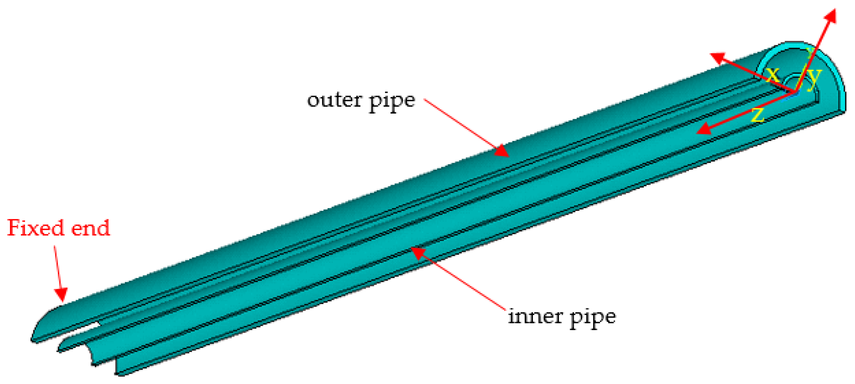
Due to the symmetricity of the structure, only a quarter of the PIP is modelled, with half of the cross-section and half of the length, as shown in Figure 4. The geometrical parameters are identical to those in the model experiment (as shown in Table 1). The initial ovality is introduced only onto the outer pipe which locates in the middle span of the pipe. The total length area of this initial ovality is 60 mm which is equal to the diameter of the outer pipe. The introduction of the above-mentioned initial ovality is realized by changing the nodes’ coordinates according to
R = R 0 + Δ 0 × R 0 cos 2 θ
The definition of ovality is as follows:
Δ 0 = D m a x D m i n D m a x + D m i n
An initial ovality of 7.85% is introduced into Case N40.
Contacts are defined between the inner surface of the outer pipe and the outer surface of the inner pipe, as well as the self-contact of the inner surface of the inner pipe. The fixed boundary condition is applied on nodes at z = 750. The external pressure is applied on the outer surface of the outer pipe.
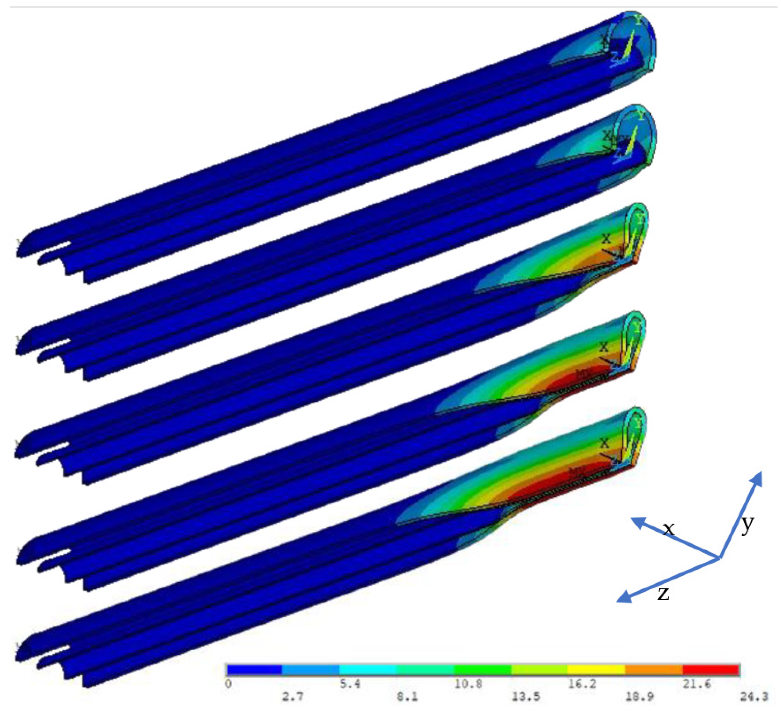
The deformation and von Mises stress distribution during the buckle propagation procedure are shown in Figure 5 and Figure 6, respectively. In such a dynamic procedure, five states are displayed in both figures. In the first state, local buckling occurs in the middle of the pipe where the initial ovality is introduced. After the second state when the outer pipe contacts the inner pipe, self-contact of the inner pipe is observed in the third state. Then in the last two states, the buckle propagates along the axial direction of the PIP system.
The ultimate collapse pressure and buckle propagation pressures are 31.39 MPa and 16.30 MPa, respectively. After comparing with the results obtained from the model experiment, the errors are 6.27% and 8.81%, respectively, which indicates an acceptable accuracy provided by the finite element model. Thus, in the following numerical simulation of this research, similar parameter settings were adapted.

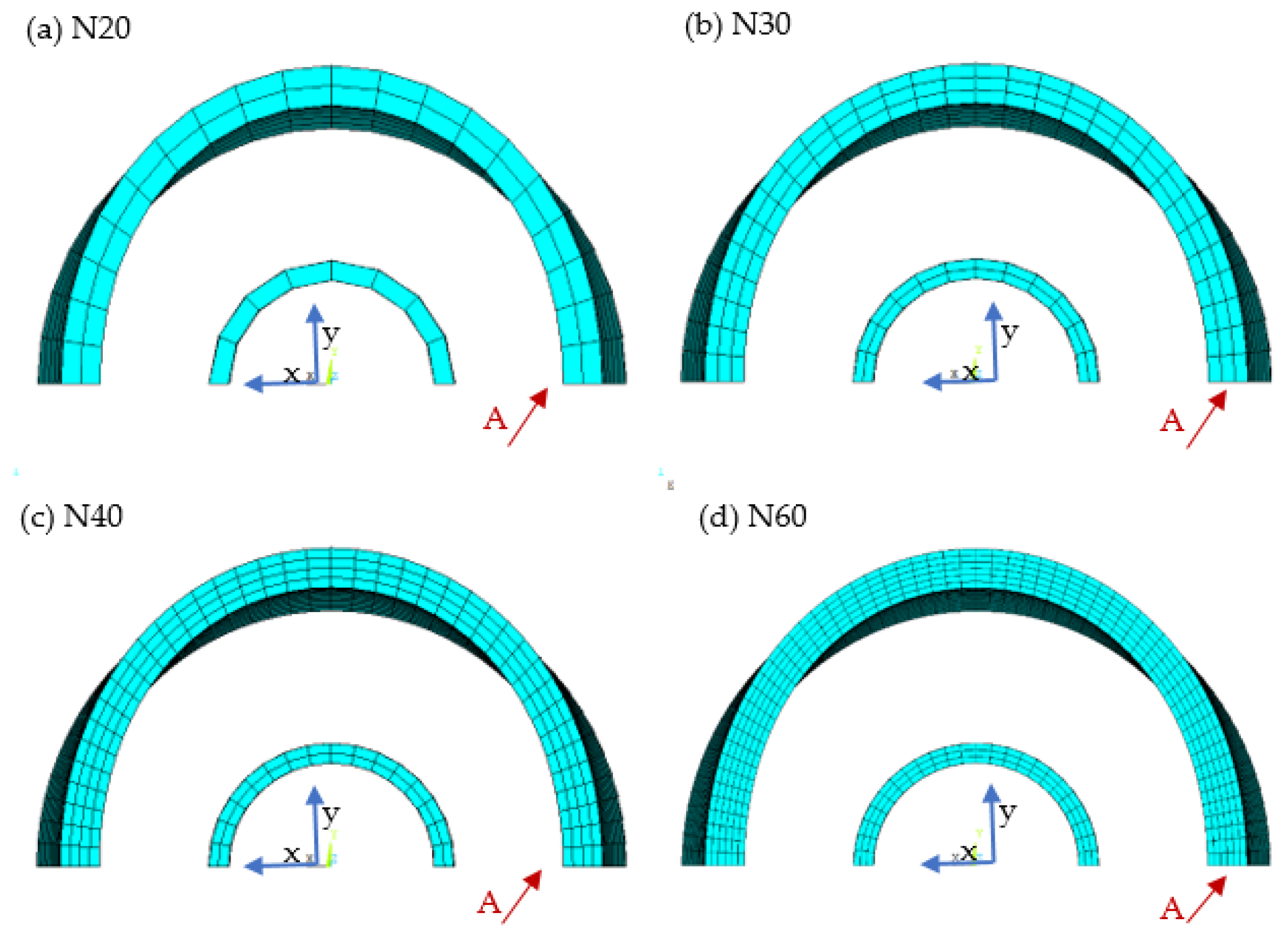
2.2. Effect of Mesh Sensitivity

To figure out the mesh division with good computing efficiency and simultaneously acceptable accuracy, four cases are further calculated. Considering the geometrical parameters shown in Table 1, different mesh divisions are presented in the new finite element models, as shown in Figure 7.
The details of element number and size in the four models are listed in Table 2. These four cases are in the N-series named by the mesh number of the outer pipe in the circumferential direction. The comparison between the results obtained from the N-series cases and the experiments is listed in Table 3. The result of the external pressure with respect to the displacement in the cross-sections of the models is shown in Figure 8. The displacement of the cross-section is represented by the displacement in the x-direction of the node belonging to the outer surface of the outer pipe with the maximum initial ovality as shown in Figure 7.
An inflexion exists in the curves in Figure 8 when the displacement is approximately 11 mm. At this moment, the contact between the outer and the inner pipes occurs. Consequently, the carrying capacity of PIP starts to increase because the inner pipe starts to participate in the resistance to structural deformation.
Despite the fact that Case N60 has the minimum errors compared with the experiment, the large element number of Case N60 indicates a great computational effort required. Case N40 utilizes 1/3 elements of those used in N60 but obtains similar accuracy. Thus, in the following calculations, the mesh division of Case N40 is applied.
Moreover, in terms of the initial dent area, the length is set to be 60 mm in the following cases.

3. Effect of Inner Pipe Imperfection

In the previous section, the initial ovality is merely introduced onto the outer pipe. The inner pipe is kept perfect, and concentric with the outer pipe. In this section, the effects of two imperfection patterns (ovality and eccentricity) of the inner pipe are checked.

3.1. The Effect of Inner Pipe Ovality

The direction of ovality is defined as the same as the minor axis of the oval. At first, the influence of the angles between directions of ovality of the outer and inner pipe is tested. Two cases are created based on Case N40, with the initial ovality of the inner pipe of a value of 7.85%. The length of the initial ovality area of the inner pipe is the same as that of the outer pipe and locates at the same position in the axial direction of the pipe. The only difference between these two cases is the direction of the inner pipe ovality. In one case, it is the same as that of the outer pipe, while in the other, it is vertical to that of the outer pipe, as shown in Figure 9.
The comparison of pipe strength between both cases is listed in Table 4. In addition to the ultimate collapse pressure and buckle propagation pressure, another two featured pressures Pt and Pi are listed to represent the occurrence of the contact. Pt is the pressure under which the outer pipe contacts the inner pipe while Pi is the pressure under which the inner surface of the inner pipe contacts itself. As shown in Table 4, in both cases, the buckle propagation pressure is the same. The difference in the values of the pressure when contact occurs between both cases is due to the geometrical features. From Figure 8, the external pressure decreases after the ultimate collapse pressure is reached. A larger distance of the gap between two pipes results in a lower value of Pt. So, this pressure is smaller in the case of the same ovality direction. Additionally, the same reason leads to the difference in values of Pi. Nevertheless, the difference between these two cases is insignificant. Thus, it is confirmed that the direction of the ovality of the inner pipe does not influence the buckle propagation of PIP.

3.2. Effect of Eccentricity

The maximum eccentricity of the inner pipe locates in the middle of the PIP in the axial direction, the same as for the ovalities of the outer and inner pipes. The degree of eccentricity, e0, is defined as follows:
e 0 = e m a x D o D i / 2
where, emax is the maximum offset of the inner pipe centre, as shown in Figure 10.
The eccentricity is introduced as a sinusoidal wave during the axial direction of the pipe, from zero in the boundary to the maximum in the middle. The geometrical parameters follow the same settings in Case N40, with the details listed in Table 5. Slight differences are observed when introducing different combined types of the initial imperfection of the inner pipe. The finite element model of Case N40.03 is shown in Figure 10, considering e0 as 0.5 which is far beyond the acceptable range in the manufacturing stage.
In the notation of the cases, the first number after the decimal sign shows two different levels of ovality: ‘0’ for no ovality and ‘1’ for an ovality of 7.85%. The second number after the decimal sign, which is also the last number in the notation, is used to identify the levels of eccentricity: ‘1’, ‘2’, and ‘3’ stand for the eccentricity of 0.1, 0.3, and 0.5, respectively. An ovality with a value of 7.85% is also at a high level of imperfection [16,17,18]. In this regard, the initial imperfection introduced in this section considers the severe situation of the PIP system.
For the sake of further confirmation of the effects of these parameters, additional cases are created in a similar method as those shown in Table 5 by changing the diameter and thickness of the inner pipe. By checking the results, it is confirmed that the imperfection of the inner pipe, neither the ovality of the inner pipe nor the eccentricity, has an insignificant influence on the buckle propagation pressure, which was also verified in the case of sandwich pipes by Fu et al. [19]
After the validation in this section, in the following numerical simulation cases, the length of PIP is set to be 1500 mm, and the initial imperfection introduced onto PIP is only the ovality on the outer pipe with a value of 7.85%.

4. Effect of the Geometry of the Inner Pipe

When checking the influence of the initial imperfection of the inner pipe in the previous section, the geometrical parameters of the inner pipe varied. In this section, the names of cases are defined as ‘Do-to-Di-ti’. For instance, the name of the case in the first line of Table 6 is ‘60-4-10-2’.
In this section, besides Case ‘60-4-25-2’ (N40), five more ratios of Di/ti are selected. Five cases with a constant Di of 25 mm and another five cases with the same ti as 2 mm are shown in Table 7. The ultimate collapse strength of PIP equals that of the outer pipe. Thus, because the outer pipes of cases listed in Table 7 share the same geometrical parameters, the ultimate collapse strength is not presented.
From the listed results in Table 7, it is noticed in Case ‘60-4-15-2’ and Case ‘60-4-25-3.33’, in which the value of the ratio (Do/to)/(Di/ti) is equal to 2 in both cases, the buckle propagation mode is different. It is supposed that the buckle propagation mode is influenced by the ratio of (Do/to)/(Di/ti), but the ratio is not a fixed value.

5. Effect of the Geometry of the Outer Pipe

In this section, the effect of the geometrical parameters of the outer pipe is investigated. First, the thickness of the outer pipe is changed in the range of 2–6 mm. The results of ultimate collapse pressure and buckle propagation pressure, as well as the buckle propagation mode, are listed in Table 8. It is observed that the buckle propagation mode switches at the thickness of the outer pipe in the range of 3–3.5 mm.
Then, to check the effect of the diameter of the outer pipe, new cases are created considering similar ratios of Do/to as those shown in Table 8, in which Case N40 is included. These cases maintain the thickness of the outer pipe at the value of 4 mm, as listed in Table 9. By comparing the results listed in Table 8 and Table 9, it is noticed that the buckling mode of Case ‘80-4-25-2’ is Mode A, whereas that of Case ‘60-3-25-2’ is Mode B, although the ratio of Do/to is the same in both cases.

6. Critical Parameter of Two Different Buckle Propagation Modes

The ratio of Do/Di for the PIP system is generally in the range of 1.3 to 2.2 [20,21,22,23,24,25]. Additional series of cases were created in the present study and calculated with outer pipe diameters of 32 mm and 36 mm. In both series, the other geometrical parameters were kept the same as in Case N40. To figure out the boundary between the two different buckle propagation modes, the thickness of the outer pipes of the cases listed in Table 9 is changed with an increment of 0.1 mm. The purpose is to illustrate the switch of the buckle propagation mode from one to another. The thickness of the outer pipe from both buckle propagation modes is summarized in Table 10.
It is confirmed that the boundary value of the ratio (Do/to)/(Di/ti) is indeed influenced by the ratio Do/Di. The relationship between (Do/to)/(Di/ti) ratio and the Do/Di ratio is shown in Figure 11, where a monotonically decreasing tendency is observed.

7. Buckle Propagation Pressure of a PIP System

In the process of pointing out the boundary between two buckle propagation modes, a large number of numerical simulation cases was created and calculated. In this section, the buckle propagation pressure of the PIP system is studied. Both Alrsai et al. [7] and Gong and Li [15] derived empirical equations of buckle propagation pressure. Both equations are made up of a combination of separated parameters together. Based on the results of the present research, the semi-empirical formula is derived to describe the relationship between buckle propagation pressure and the geometrical parameters of the PIP system.
Both effects of the ratio Do/to and Di/ti were investigated. For the case with diameters of the outer and inner pipes as 60 mm and 25 mm, respectively, the buckle propagation pressure is shown in Table 11.
The relationship between the buckle propagation pressure and the D/t ratios of outer and inner pipes are illustrated in Figure 12, in which both trendlines are in the style of power functions. So, it is assumed that the buckle propagation pressure can be expressed by the following:
P P = χ D o t o α D i t i β
where, χ, α and β are related to the ratio of Do/Di, and will be explained later in this section.
To determine the expression of χ, α, and β, several new cases listed in Table 12 were analysed. The ratios of Do/to and Di/ti are in the ranges of 10 to 33 and 7 to 50, respectively. The ratio of Do/Di is in the range of 1.28 to 3.2. As pointed out in the last case in Table 11, the buckle propagation pressure did not increase to a large extent when the thickness of the inner pipe changed from 3.33 mm to 5 mm. The same phenomenon is also found in other series of calculations. So, the results of these cases are excluded from the summary.
After summarizing the results of 73 cases, the expression of χ, α, and β can be expressed as follows:
χ = 1910.5 D o D i 2 7523.7 D o D i + 13281
α = 0.3371 D o D i 1.1944
β = 0.1625 D o D i 0.5984
The comparison between the calculation results and the results predicted by Equation (7) are shown in Figure 13, which leads to the conclusion that a good agreement is achieved.

8. Conclusions

The phenomenon of buckle propagation in a PIP system under uniform external pressure was studied in this paper. After the validation of the numerical result by comparison with experiments, the buckle propagation pressures of a series of cases were obtained.
Still some limitations exist in the research of this paper. The physical properties applied in the numerical simulation, such as yield stress and Young’s modulus, are not considered to be variables in deriving the empirical equation. Thus, further research is required on the effects of physical properties as another aspect.
Despite the above limitation, several conclusions based on the results were obtained as follows:
  • The initial imperfections of PIP, i.e., the ovality and eccentricity of the inner pipe, have an insignificant influence on the buckle propagation pressure
  • The switch of two buckle propagation modes is dependent on the ratio of (Do/to)/(Di/ti) and the critical value of the ratio is related to the ratio of Do/Di; instead of that in the previous literature, the critical value is considered to be constant. In practice situations of the ratio of Do/Di in the range of 1.2 to 2.2, a monotonically decreasing tendency of (Do/to)/(Di/ti) can be observed with respect to Do/Di
  • The buckle propagation pressure is highly influenced by the ratio of Do/to and Di/ti. In other words, the strength of the outer pipe compared with the inner pipe not only results in the buckle propagation mode of PIP but also leads to the stability of the buckle propagation pressure. One phenomenon observed is that during the increase of thickness of the inner pipe, after it exceeds a certain value (such as 3.33 mm in Case 60-4-25-3.33), the buckle propagation pressure will not increase any longer in line with the increase of thickness
  • The relationship between the buckle propagation pressure and the ratio of D/t of pipes in PIP follows the format of power functions, which includes the coupling effect of the variables. Based on the results from the present analyses, a fitted formula (Equation (7)) is proposed for predicting the buckle propagation pressure of the PIP with good accuracy.

Author Contributions

R.L.: Methodology, Formal analysis, Writing—original draft, Visualization. B.-Q.C.: Methodology, Writing—original draft. C.G.S.: Conceptualization, Writing—review and editing, Supervision. All authors have read and agreed to the published version of the manuscript.

Funding

This work was developed in the scope of the project “Cementitious cork composites for improved thermal performance of pipelines for ultradeep waters”–SUPBSEAPIPE, with the reference n.◦ POCI-01-0145-FEDER-031011 funded by the European Regional Development Fund (FEDER) through COMPETE2020-Operational Program Competitiveness and Internationalization (POCI) and with financial support from the Portuguese Foundation for Science and Technology (Fundação para a Ciência e Tecnologia-FCT) under grant 02/SAICT/032108/2017. This study contributes to the Strategic Research Plan of the Centre for Marine Technology and Ocean Engineering, which is financed by FCT, under contract UIDB/UIDP/00134/2020.

Institutional Review Board Statement

Not applicable.

Informed Consent Statement

Not applicable.

Data Availability Statement

The data presented in this study are available on request from the corresponding author.

Conflicts of Interest

The authors declare no conflict of interest.

References

  1. Bai, Y.; Igland, R.T.; Moan, T. Tube collapse under combined external pressure, tension and bending. Mar. Struct. 1997, 10, 389–410. [Google Scholar] [CrossRef]
  2. Park, T.D.; Kyriakides, S. On the collapse of dented cylinders under external pressure. Int. J. Mech. Sci. 1996, 38, 557–578. [Google Scholar] [CrossRef]
  3. Vasilikis, D.; Karamanos, S.A. Stability of confined thin-walled steel cylinders under external pressure. Int. J. Mech. Sci. 2009, 51, 21–32. [Google Scholar] [CrossRef]
  4. He, T.; Duan, M.; An, C. Prediction of the collapse pressure for thick-walled pipes under external pressure. Appl. Ocean Res. 2014, 47, 199–203. [Google Scholar] [CrossRef]
  5. Timoshenko, S.P.; Gere, J.M. Theory of Elastic Stability, 2nd ed.; Dover Publications: New York, NY, USA, 1961. [Google Scholar]
  6. Liang, H.; Zhou, J.; Lin, J.; Jin, F.; Xia, F.; Xue, J.; Xu, J. Buckle propagation in steel pipes of ultra-high strength: Experiments, theories and numerical simulations. Acta Mech. Solida Sin. 2020, 33, 546–563. [Google Scholar] [CrossRef]
  7. Alrsai, M.; Karampour, H.; Albermani, F. On collapse of the inner pipe of a pipe-in-pipe system under external pressure. Eng. Struct. 2018, 172, 614–628. [Google Scholar] [CrossRef]
  8. Alrsai, M.; Karampour, H.; Albermani, F. Numerical study and parametric analysis of the propagation buckling behaviour of subsea pipe-in-pipe systems. Thin-Walled Struct. 2018, 125, 119–128. [Google Scholar] [CrossRef] [Green Version]
  9. Bhardwaj, U.; Teixeira, A.P.; Guedes Soares, C. Reliability assessment of a subsea pipe-in-pipe system for major failure modes. Int. J. Press. Vessels Pip. 2020, 188, 104177. [Google Scholar] [CrossRef]
  10. Netto, T.A.; Estefen, S.F. Buckle arrestors for deepwater pipelines. Mar. Struct. 1996, 9, 873–883. [Google Scholar] [CrossRef]
  11. Lee, L.H.; Kyriakides, S.; Netto, T.A. On the flip-flop mode of dynamic buckle propagation in tubes under external pressure. Extreme Mech. Lett. 2021, 48, 101378. [Google Scholar] [CrossRef]
  12. Kyriakides, S.; Babcock, C.D.; Elya, D. Initiation of propagating buckles from local pipeline damages. J. Energy Resour. Technol. 1984, 106, 79–87. [Google Scholar] [CrossRef]
  13. Kyriakides, S.; Vogler, T.J. Buckle propagation in pipe-in-pipe systems: Part II. Analysis. Int. J. Solids Struct. 2002, 39, 367–392. [Google Scholar] [CrossRef]
  14. Wierzbicki, T.; Bhat, S.U. Initiation and propagation of buckles in pipelines. Int. J. Solids Struct. 1986, 22, 985–1005. [Google Scholar] [CrossRef]
  15. Gong, S.; Li, G. Buckle propagation of pipe-in-pipe systems under external pressure. Eng. Struct. 2015, 84, 207–222. [Google Scholar] [CrossRef]
  16. Li, R.; Guedes Soares, C. Numerical study on the effects of multiple initial defects on the collapse strength of pipelines under external pressure. Int. J. Press. Vessels Pip. 2021, 194, 104484. [Google Scholar] [CrossRef]
  17. Li, R.; Chen, B.Q.; Guedes Soares, C. Design equation for the effect of ovality on the collapse strength of sandwich pipes. Ocean Eng. 2021, 235, 109367. [Google Scholar] [CrossRef]
  18. Li, R.; Chen, B.Q.; Guedes Soares, C. Effect of ovality length on collapse strength of imperfect sandwich pipes due to local buckling. J. Mar. Sci. Eng. 2022, 10, 12. [Google Scholar] [CrossRef]
  19. Fu, G.; Li, M.; Yang, J.; Sun, B.; Shi, C.; Estefen, S.F. The effect of eccentricity on the collapse behaviour of sandwich pipes. Appl. Ocean Res. 2022, 124, 103190. [Google Scholar] [CrossRef]
  20. Binazir, A.; Karampour, H.; Sadowski, A.J.; Gilbert, B.P. Pure bending of pipe-in-pipe systems. Thin-Walled Struct. 2019, 145, 106381. [Google Scholar] [CrossRef]
  21. Jiwa, M.Z.; Kim, D.K.; Mustaffa, Z.; Choi, H.S. A systematic approach to pipe-in-pipe installation analysis. Ocean Eng. 2017, 142, 478–490. [Google Scholar] [CrossRef]
  22. Karampour, H.; Alrsai, M.; Albermani, F.; Guan, H.; Jeng, D.S. Propagation buckling in subsea pipe-in-pipe systems. J. Eng. Mec. 2017, 143, 04017113. [Google Scholar] [CrossRef] [Green Version]
  23. Sun, C.; Zheng, M.; Guedes Soares, C.; Duan, M.; Wang, Y.; Onuoha, M.D.U. Theoretical prediction model for indentation of pipe-in-pipe structures. Appl. Ocean Res. 2019, 92, 101940. [Google Scholar] [CrossRef]
  24. Zhang, Z.; Liu, H.; Chen, Z. Lateral buckling theory and experimental study on pipe-in-pipe structure. Metals 2019, 9, 185. [Google Scholar] [CrossRef] [Green Version]
  25. Zhang, X.; Duan, M.; Guedes Soares, C. Lateral buckling critical force for submarine pipe-in-pipe pipelines. Appl. Ocean Res. 2018, 78, 99–109. [Google Scholar] [CrossRef]
Figure 1. Buckle propagation mode in the 2D scenario: (a) single-walled pipe, (b) PIP, and (c) single-walled pipe.
Jmse 11 00622 g001
Figure 2. Two different buckle propagation modes in a PIP system.
Jmse 11 00622 g002
Figure 3. Strain–stress curve applied in numerical calculation.
Jmse 11 00622 g003
Figure 4. Geometrical model of the PIP in Case N40.
Jmse 11 00622 g004
Figure 5. Deformation of PIP system during buckle propagation of Case N40 (unit: mm).
Jmse 11 00622 g005
Figure 6. Distribution of von Mises stress during buckle propagation of Case N40 (unit: MPa).
Jmse 11 00622 g006
Figure 7. Mesh divisions of N-series cases from the back view: (a) Case N20, (b) N30, (c) N30, (d) N60.
Jmse 11 00622 g007
Figure 8. Relationship between external pressure and displacement of cross-section.
Jmse 11 00622 g008
Figure 9. Directions of ovality of outer and inner pipe: (a) same and (b) vertical.
Jmse 11 00622 g009
Figure 10. Model and mesh of Case N40.03: (a) back view and (b) bottom view.
Jmse 11 00622 g010
Figure 11. Critical (Do/to)/(Di/ti) ratio of Mode A and B.
Jmse 11 00622 g011
Figure 12. Relationship between buckle propagation pressure and D/t ratios: (a) outer pipe and (b) inner pipe (Do = 60 mm, Di = 25 mm).
Jmse 11 00622 g012
Figure 13. Comparison between the calculation results and results from Equation (7).
Jmse 11 00622 g013
Table 1. Geometrical parameters and physical properties of the pipe in the model experiment; the data are from [15].
L (mm)D (mm)t (mm)Δ0 (%)σ0.5 (MPa)E (GPa)
Outer pipe15006047.85319.2188.9
Inner pipe15002520319.2188.9
Table 2. Detail mesh division of N-series.
CaseElement Size (mm)Mesh NumberTotal Number
θtzθtz
N20outer pipe9.4221020215013,800
inner pipe9.8221081150
N30outer pipe6.281.337.530320036,000
inner pipe6.5417.5122200
N40outer pipe4.711540430084,000
inner pipe4.9115162300
N60outer pipe3.140.673.75606400225,600
inner pipe3.270.673.75243400
θ-circumferential direction; t-thickness direction; z-axial direction.
Table 3. Comparison results between N-series and experiment.
CaseUltimate Collapse Pressure (Pco)Buckle Propagation Pressure (Pp)
FEM (MPa)Experiment (MPa)Error (%)FEM (MPa)Experiment (MPa)Error (%)
N2034.1229.5415.5019.5014.9830.17
N3032.2129.549.0417.0014.9813.48
N4031.3929.546.2716.3014.988.81
N6030.7529.544.1015.5514.983.81
Error = (FEM − Experiment)/Experiment × 100%.
Table 4. Effect of ovality direction.
Direction of OvalityPco (MPa)Pt (MPa)Pi (MPa)Pp (MPa)
a. same31.3916.2915.7716.30
b. vertical31.3916.9515.4616.30
Pt: pressure under which outer pipe touches inner pipe; Pi: pressure under which inner pipe contacts itself.
Table 5. The initial imperfection of the inner pipe.
Case Δ ie0Pco (MPa)Pt (MPa)Pi (MPa)Pp (MPa)
N400031.3915.6615.6616.30
N40.0100.131.3915.9515.6816.33
N40.0200.331.3915.8615.6916.35
N40.0300.531.3915.7915.6916.35
N40.117.850.131.3914.9215.8616.30
N40.127.850.331.3915.2815.8416.35
N40.137.850.531.3915.2415.8516.40
Table 6. Cases with different geometrical parameters of the inner pipe.
Do (mm)to (mm)Di (mm)ti (mm)
604102
604152
604202
604302
604352
604251.43
604251.67
604252.5
604253.33
604255
Table 7. Geometry and buckle propagation of PIP with the same outer pipe (Do = 60 mm, to = 4 mm).
Di (mm)ti (mm)Do/DiDi/ti(Do/to)/(Di/ti)Pp (MPa)Mode
2522.412.501.2016.30A
10265.003.0015.80B
15247.502.0015.90A
202310.001.5016.10A
302215.001.0016.50A
3521.7117.500.8617.10A
251.432.417.480.8615.75A
251.672.414.971.0015.95A
252.52.410.001.5017.00A
253.332.47.512.0018.50B
2552.45.003.0018.70B
Mode A: The buckle propagation occurs after the contact between the upper and lower parts of the inner surface of the inner pipe; Mode B: During buckle propagation, the inner surface of the inner pipe maintains a distance away from contact.
Table 8. Effect of thickness of the outer pipe.
Caseto (mm)Do/toPco (MPa)Pp (MPa)Mode
60-3-25-23.02019.508.75B
60-3.5-25-23.517.1425.1011.95A
60-4-25-2 (N40)4.01531.3916.30A
60-4.5-25-24.513.3337.8021.10A
60-5-25-25.01244.8327.00A
60-5.5-25-25.510.9152.0933.70A
60-6-25-26.01059.7641.20A
Table 9. Effect of the diameter of the outer pipe.
CaseDo (mm)Do/toPco (MPa)Pp (MPa)Mode
80-4-25-2802020.617.95A
68.58-4-25-268.5817.1526.0711.75A
60-4-25-2 (N40)601531.3916.30A
53.4-4-25-253.3413.3437.0222.10A
48-4-25-2481244.2631.00A
43.6-4-25-243.610.950.1539.40A
40-4-25-2401057.3251.00A
Table 10. The thickness of the outer pipe from both buckle propagation modes of cases with Do/Di less than 2.2 (Di = 25 mm, ti = 2 mm).
Do (mm)Do/Dito (mm)(Do/to)/(Di/ti)
Mode AMode BMode AMode B
53.342.133.131.381.42
481.922.72.61.421.48
43.61.742.32.21.521.59
401.602.01.91.601.68
361.441.81.71.601.69
321.281.51.41.711.83
Table 11. Buckle propagation pressure of PIP (Do = 60 mm, Di = 25 mm).
to (mm)ti (mm)Do/DiDo/toDi/tiPp (MPa)
422.41512.516.30
3.222.418.7512.59.95
3.122.419.3512.59.35
322.42012.58.75
2.722.422.2212.57.20
41.432.41517.4815.75
41.672.41514.9715.95
422.41512.516.30
42.52.4151017.00
43.332.4157.5118.50
452.415518.60
Table 12. Calculated series for the effect of Do/Di.
Do (mm)Di (mm)Do/toDi/ti
8025
68.5825
6025
53.3425
4825
43.625
4025
3625
3225
Disclaimer/Publisher’s Note: The statements, opinions and data contained in all publications are solely those of the individual author(s) and contributor(s) and not of MDPI and/or the editor(s). MDPI and/or the editor(s) disclaim responsibility for any injury to people or property resulting from any ideas, methods, instructions or products referred to in the content.

