Abstract
Horizontal wells, extended-reach wells, and multi-branch wells were often used to exploit subsea oil and gas efficiently. However, during the sand control screen completion of those wells, the sand control screen pipe was easily deformed. Failure occurred when passing through the bending section due to the large bending section in the wellbore trajectory. A parametric analysis model of the screen pipe was established based on ABAQUS and Python software under pure bending load first. Then, deformation patterns and mechanisms were identified and discussed. The effects of parameters on the screen pipe bending deformation patterns and the ultimate moment were analyzed. Finally, an empirical formula for calculating the ultimate moment of the screen pipe was established. The results showed that the deformation of the screen pipe was complex, and three deformation patterns were related to the hole parameters. Due to an increase in the diameter and number of circumferential and axial holes, the ultimate moment of the screen pipe gradually decreased, and the circumferential holes had a more significant effect on the ultimate moment than the axial holes. The established empirical formula could accurately calculate the ultimate moment of the screen pipe, and the average difference between the formula and numerical simulation results was 3.25%.
1. Introduction
Considering onshore oil and gas resource depletion, attention had been gradually focused on offshore oil exploration and development. However, sand production problems were often encountered during offshore and onshore unconsolidated sandstone reservoir development [1,2,3]. Excessive sand production in reservoir formations during exploitation reduces the production and damages the production equipment [4,5,6]. Therefore, it was necessary to adopt reasonable sand control measures to prevent excess sand from entering the wellbore. Currently, sand control screen pipes were the leading sand control equipment in fields. During the development of onshore and offshore oilfields, it is necessary to run sand control screens pipe to prevent massive formation sand production. For offshore screen pipes completion, the screen pipes enter the production formation of oil and gas through the riser and wellbore from the well head of the offshore platform. The screen enters the formation through the curved well section of the horizontal well is one of the processes of offshore screen completion. The screen pipe is made by perforating the pipe according to certain rules, and its shape is similar to the complete pipe. The geometry and hole parameters of screen pipes are designed according to operating conditions and oil and gas production. Commonly used materials for screen pipes are K55, J55, N80 steel, and so on. The base pipe made of perforated pipes was the main component of the sand control screen pipes to bear the loading.
With the increase in oil and gas production and consequent economic benefits, horizontal wells, extended reach wells, and multi-branch wells were often used on-site. Those well types could expand the exploitation scope of oil and gas wells without offshore platform restrictions. However, the well trajectories of those well types had a large, curved section [7,8], as shown in Figure 1. During the sand control screen completion of those wells, the screen pipes encounter a large bending load when entering the formation through the curved section [9,10], as shown in Figure 1. Because a complete pipe perforates the base of the screen pipe, the holes reduce the bearing capacity of the screen pipe, as shown in Figure 1. Moreover, the screen pipes may be bent and damaged due to the formation collapse or formation settlement during the production process. Since the acidic component exists in oil and gas in formation, the screen pipes were corroded. The longer the production time, the more serious the corrosion of the screen pipe was, and the bending strength performance of the screen pipes decreased. Plastic deformation and fracture occurred around the screen pipe body and hole when the pipe was subjected to a large bending load. This results in the failure of the sand control screen, which considerably threatened the average production of oil and gas wells. Therefore, it was necessary to analyze the deformation behavior of a screen pipe under a bending load and calculate the ultimate bending strength.
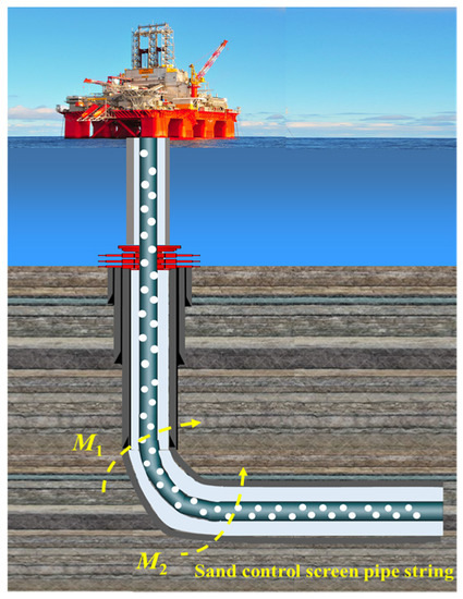
Figure 1.
Loads acting on the curved section of the screen pipe.
The research activities on the ultimate bending moment of intact and corroded pipes under bending loads were relatively mature. The main research approaches include the finite element method, experimental tests, and analytical treatment. Compared with the previous research object, the structure of the screen pipe was more complex. The bending deformation mechanism of the screen pipe under bending load needed to be clarified, and the lack of a corresponding formula for calculating the ultimate bending moment of the screen pipe caused difficulties in evaluating the ultimate strength.
Chen et al. [11] proposed a simplified method for predicting the ultimate bending strength of a pipeline based on Hencky’s total strain theory. The results showed that the simplified model was consistent with the experimental results in predicting the ultimate bending capacity of steel pipes, and the strain-hardening effect significantly influenced the ultimate bending capacity of steel pipes. Adam et al. [12] established a nonlinear finite element model (FEM) of the plastic buckling of cylindrical metal tubes and shells under a bending load using ABAQUS software. They compared the applicability and economy of continuous and shell finite elements in simulating the pipe-bending deformation. Chen et al. [13] established a theoretical model of the residual bending strength of a corroded screen pipe under combined internal pressure and axial load. They analyzed the influence of different corrosion shapes on the residual strength of the pipe. Using ABAQUS, Kumar et al. [14] established a FEM of the buckling of cylindrical shells under a pure bending load. They analyzed the influence, sensitivity, and impact of steel strain hardening models on the bending behavior of cylindrical shells. Moreover, using ABAQUS, Erling et al. [15,16] also established a FEM for a pipeline with a peripheral surface crack under a pure bending load and combined bending load and internal pressure. They analyzed the evolution law of the crack tip opening of the cracked pipeline and the effects of crack depth, length, diameter–thickness ratio, and material hardening on the fracture response. Behrouz [17] analyzed the influence of corrosion depth and shape on the strength of corroded pipes under combined internal pressure and bending load based on experiments and FEMs. Based on numerical simulation data, Hieu et al. [18] established an empirical formula for the ultimate bending capacity of pipes with corrosion defects under axial loads. Sjors [19,20] analyzed the ultimate bending capacity of spiral-welded steel tubes based on experiments and FEMs. Limam A et al. [21,22] analyzed the inelastic wrinkling of intact tubes and the effect of local dents on the collapse curvature of pipes under combined bending and internal pressure with experiment and FEM method. Fu Guangming et al. [23] and Peng Yudan [24] established finite element model of the screen pipes under external pressure and combined external pressure and bending load with the finite element method, and the influence of different parameters on the collapse strength of the screen pipes was analyzed, and the corresponding calculation formula for the collapse strength of the screen pipes were established. Kyriakides and Corona [25] and Karampour and Albermani [26] studied the plastic bending strength of pipes under bending load based on experiment and finite element method, and the results of simulation and experiment were compared. Karampour [27] studied the lateral buckling of pipelines with nonlinear soil pipe interaction based on the finite element analysis method, and an analytical solution for lateral buckling of pipes with a single defect was proposed. Taheri et al. [28] analyzed the linear eigenvalue bucking and nonlinear post bucking of sandwich pipes under bending loads based on the finite element method, and the influence of structural parameters of sandwich pipes on pre-bucking, bucking, and post bucking responses was analyzed. Binazir et al. [29] analyzed the linear bifurcation and geometrically nonlinear behavior of pipe in pipe under bending loads based on experiments and finite element methods and proposed a formula for calculating the ultimate bending moment of pipe in pipe.
In the present work, a FEM of the bending deformation of a screen pipe under pure bending was established based on ABAQUS and Python script. The sand control screen pipe’s bending deformation patterns and mechanism were discussed in detail, and the influence of the screen pipe and hole arrangement parameters on the bending deformation and ultimate moment of the screen pipe were analyzed. Furthermore, an empirical formula for calculating the ultimate moment of the screen pipe under a bending load was established.
2. Numerical Simulation Model of the Sand Control Screen Pipe under Bending
2.1. Finite Element Model
This study adopted the parallel hole arrangement in a perforated screen pipe. Because a screen pipe with a parallel hole arrangement was symmetrical, a 1/2 symmetrical model was used to simplify the calculation, as shown in Figure 2. The screen pipe was severely deformed under a bending load, and C3D8R element, which had the advantages of high accuracy and no shear self-locking even when the mesh was severely deformed [30], was employed to simulate the screen pipe under bending. The mesh sensitivity analysis was carried out, as shown in Figure 3. When the mesh number is around 210,570, the ultimate moment of the screen pipes tends to stabilize, and as the mesh number continues to increase, the ultimate moment of the screen pipes changes slightly. Therefore, the mesh number of 210,570 was employed in the present work. The length of the screen was ten times greater than the diameter of the pipe to reduce the influence of the ending effect on the bending deformation of the screen pipe.
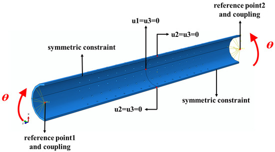
Figure 2.
The FEM of screen pipe and boundary condition.
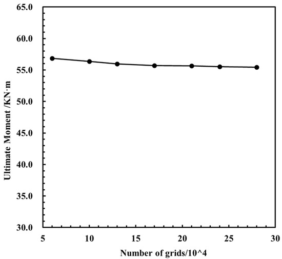
Figure 3.
Mesh sensitivity analysis.
Figure 2 shows the load and boundary conditions of the model. The reference points were set at the center of the two end faces of the screen pipe and were coupled with the faces. Symmetry constraints were applied to the symmetry plane, and a corresponding displacement constraint was applied to the one half screen pipe length nodes to eliminate the rigid body displacement of the pipe in different directions during loading [31]. The same rotation angle was applied to the coupling points at both ends of the pipe to apply a bending load. Additionally, general analysis steps were adopted, and the screen pipe’s ultimate moment and rotation angles were obtained in a rotation angle-moment curve. The elastic modulus, plastic strength, and Poisson’s ratio of this material were 203 GPa, 464.36 MPa, and 0.3, respectively [23]. The isotropic hardening behavior of screen pipe material was assumed, and the stress–strain curve of the screen pipe material is shown in Figure 4.
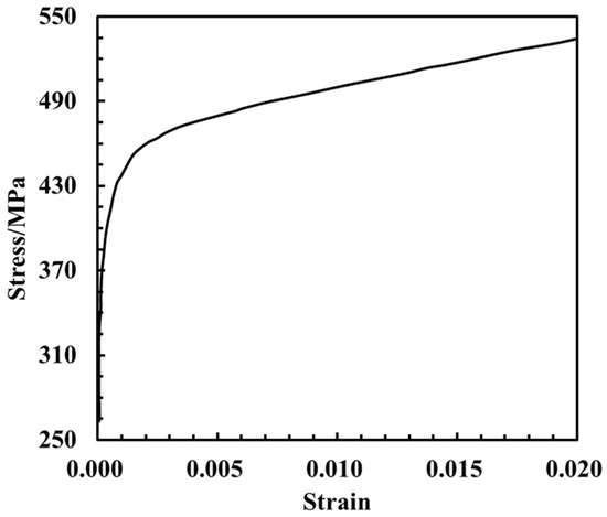
Figure 4.
Material property of the sand control screen.
2.2. Secondary Development of FEM
ABAQUS provided a secondary development interface [32,33]. A parametric analysis model of the ultimate moment of screen pipe under bending load was established based on the secondary development of ABAQUS by Python script. The secondary development process is shown in Figure 5, and its main difficulty was realizing a regular arrangement of hole parameters and parameterization. Secondary development of FEMs significantly simplified the tedious modeling process and laid the data foundation for the study of the deformation pattern of screen pipe as well as the establishment of the empirical formula of the ultimate moment.
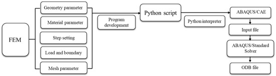
Figure 5.
Secondary development process of FEM.
2.3. Numerical Results Discussion
The screen pipe’s bending deformation patterns and mechanism under bending load were currently unclear. Therefore, the bending deformation of the screen pipes with different screen parameters, as listed in Table 1, was analyzed based on FEM.

Table 1.
Screen pipes parameter commonly used in the field.
Numerous results of screen pipe deformation indicated that the deformation could be divided into three patterns: In pattern-1, the screen pipe buckled from the middle position, and the hole area did not fracture. In pattern-2, the screen pipe first buckled from the middle position, and plastic deformation occurred around the hole area, which eventually fractured as the bending load increased. In pattern-3, plastic deformation occurred around the fractured hole area. However, the deformation around the middle of the screen pipe was small.
The three bending deformation patterns of screen pipes were discussed in detail as follows from different aspects, such as the relationship between the rotation angle and moment, ovality change laws at the middle section of the screen pipe and fracture section around the holes, and stress and strain laws at the middle position of the screen pipes and fracture position around the holes.
2.3.1. Pattern-1
As the bending load increased, the screen pipe buckled from the middle position. However, the hole area did not fracture. Figure 6 shows the screen pipe’s moment-rotation angle relationship in the pattern-1, which was divided into four stages. In stage-1, as the bending load increased, the bending moment sharply increased, and the stress and bending deformation were small, as shown in #1. In stage-2, as the bending load increased, the bending moment gradually reduced, whereas the deformation and stress gradually increased, as shown in #2. In stage-3, as the bending load gradually increased, the increasing speed of the bending moment tended to stabilize, and the bending deformation gradually increased, as shown in #3. The deformation and stress of the screen pipe when the ultimate bending moment was reached are shown in #4. In stage-4, when the bending load was increased after reaching the ultimate bending moment, the bending moment of the screen sharply decreased. However, the bending deformation continued to increase, whereas the stress at both ends of the screen gradually decreases, causing the screen pipe to buckle from the middle position, as shown in #5. Meanwhile, there was no deformation around the hole area.
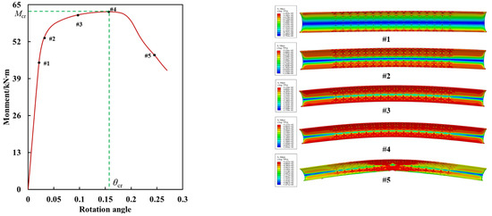
Figure 6.
Moment versus rotation angle and stress contour of screen pipes.
The deformation was most significant at the middle position of the screen pipe, which is the central area of concern. Therefore, the ovality, stress, and strain in the middle of the screen tube are discussed in detail here. Figure 7a,b show the middle section of the screen pipe and the ovality curve with the rotation angle of the middle section, respectively. The curve could be roughly divided into three stages: In the first stage, when the rotation angle was less than the critical rotation angle, the ovality of the section gradually increased as the rotation angle increased, and the deformation of the screen pipe was small. In the second stage, the ovality and deformation sharply increased with an increase in the rotation angle after the angle reached the critical angle. In the third stage, as the rotation angle increased, the increase in ovality tended to stabilize, and the deformation of the screen pipe continued to increase.
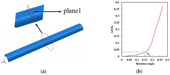
Figure 7.
(a) Middle section of screen pipe; (b) Curve of ovality versus rotation angle.
Figure 8 shows the selection of normalized elements and nodes in the middle of the screen pipe. Figure 9 shows the stress and strain contours of the selected nodes and elements on the compression and tension sides of the screen pipe during the bending process. In Figure 9a,b, the stress and strain contours about the middle position were symmetrical. When θ < 0.016, the stress difference of the nodes at different positions was small. As the rotation angle increased, the nodes on both sides reached the yield stress first compared to the middle nodes at the same θ. The stress in the middle position and on both sides fluctuated after θ > θcr. In contrast, when θ < 0.0195, the strain of the elements on both sides was more significant than that of the central elements. It was because the stress at both sides reached the yield state first. The strain in the middle position was gradually greater than those on both sides, and the closer the position was to the middle, the greater the strain, causing the screen pipe to buckle from the middle position on the compression side.
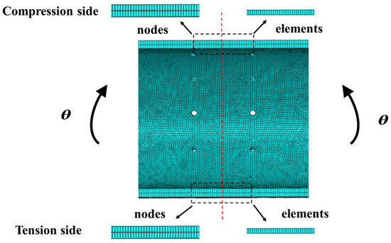
Figure 8.
The selected elements and nodes of screen pipe.
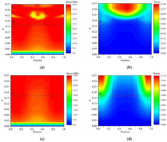
Figure 9.
(a,b) stress and strain on compression side; (c,d) stress and strain on the tensile side.
Figure 9c,d shows the stress and strain contours on the tensile side, which were symmetrical about the middle position. Although the stress variation law on the tensile side was similar to that on the compression side, the rotation angle to yield stress at the middle position was more significant on the tensile side. The stress of the nodes at different positions did not change after reaching the yield stress. However, the strain on the tensile side of the screen pipe was opposite to that on the compression side: the closer the element was to the middle position, the smaller the strain. In addition, the strain on the tensile side was less than on the compression side at the same angle rotation and corresponding elements.
2.3.2. Pattern-2
As the bending load increased, the screen pipe first exhibited overall bending deformation, and buckling deformation occurred at the middle position. In contrast, plastic deformation and fracture occurred around the hole area. The moment–rotation angle curve was divided into five stages, as shown in Figure 10. The first four stages were similar to those of pattern-1 and will not be repeated here. In stage-5, as the bending load increased, the deformation of the middle position of the screen pipe increased, and plastic deformation appeared around the hole area, which gradually evolved into a fracture. The deformation and stress of the screen pipe are shown in #6.
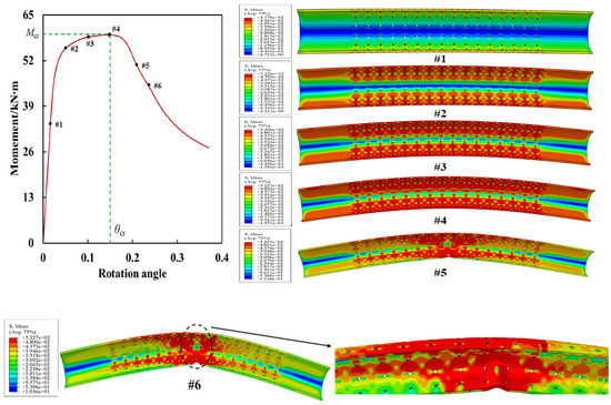
Figure 10.
Moment versus rotation angle, and stress contour of screen pipes.
Meanwhile, the deformations at the middle position and hole area were significant, the main areas of concern. Therefore, the ovality, stress, and strain at the middle position and the area around the hole are discussed in detail here. Figure 11a shows the middle and plastic deformation hole sections (planes 1 and 2, respectively), and Figure 11b shows the ovality curve with the rotation angles of planes 1 and 2. The curve could be divided into three regions: In the first region (θ < θcr), as the rotation angle increased, the ovality of planes 1 and 2 gradually increased, and the deformation of the screen pipe was small. Additionally, the ovality of planes 1 and 2 was approximately equal, indicating that the bending deformations of the two positions were the same. In the second region (θ > θcr), the ovality of plane 1 was greater than that of plane 2. It increased approximately in a straight line, indicating that the deformation of the hole area was more significant than that of the middle position of the screen pipe. In the third region, as the rotation angle increased, the ovality of plane 1 gradually decreased and tended to be constant, whereas that of plane 2 sharply increased, indicating that the radial deformation of the screen tube mainly occurred at the hole position.
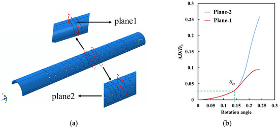
Figure 11.
(a) Middle section and hole section of screen pipe; (b) Ovality versus rotation angle.
The node stress and element strain at the middle position and the hole areas on the compression and tensile sides of the screen were discussed in detail here. Figure 12 shows the selected elements and nodes. Figure 13 shows the stress and strain of the nodes and elements in the middle position of the tensile and compression sides, respectively. The stress and strain on the compression side were similar to those of pattern-1, as shown in Figure 13a,b, which was not repeated here. The stress on the tensile side was comparable to that in the pattern-1, as shown in Figure 13c,d. Yield stress occurred only in the nodes at the middle position on the tensile side after the rotation angle reached a significant value. The strain in the nodes at the middle position gradually approached and exceeded those at both sides when the rotation angle increased to a more significant value. This difference may be due to the appearance of the plastic deformation of the hole area at the tensile side of the screen pipe, which significantly influenced the stress and strain distributions at the tensile side but slightly influenced those at the compression side.
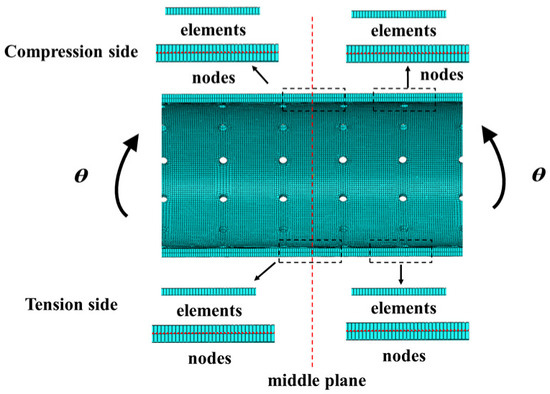
Figure 12.
Selected elements and nodes.
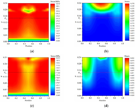
Figure 13.
(a,b) Stress and strain on the compression side of screen pipe in the middle position; (c,d) Stress and strain on the tensile side of screen pipe in the middle position.
Figure 14 shows the stress and strain of the nodes and elements around the holes on the compression and tension side. As shown in Figure 14a, when θ < 0.02, the node stresses at different positions were equal under the same rotation angle. When 0.02 < θ < 0.08, the stress increased and then decreased as the position was closer to the middle. When 0.08 < θ < 0.2, the node stress values at different positions were consistent under the same rotation angle. When 0.2 < θ, the node stress gradually decreased at the same node position, which differed from the stress variation in the middle position of the screen pipe. As shown in Figure 13b, the strain in the middle position of the hole was the smallest. When θ < 0.04, the strain difference of each element was small. When 0.04 < θ, the strain of the screen pipe first increased and then decreased as the unit position approached the middle position of the hole.
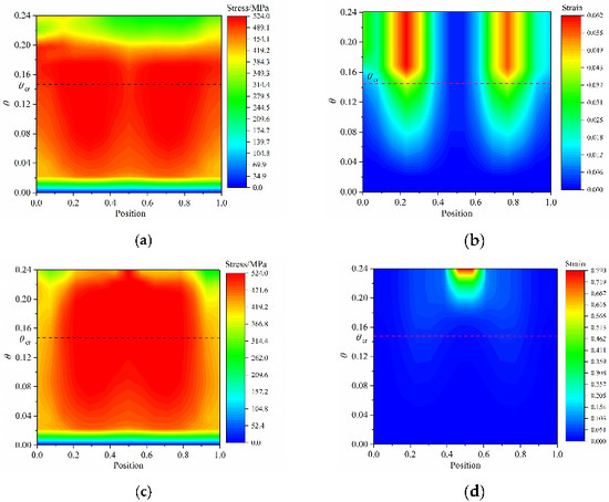
Figure 14.
(a,b) stress and strain on the compression side around the holes; (c,d) stress and strain on the tension side around the holes.
Figure 14c,d shows the stress and strain at the nodes and elements on the tensile side. As shown in Figure 14c, when θ > 0.08, the stress in the middle position of the hole gradually reached the maximum stress and was more significant than those on both sides of the pipe. When θ < 0.16, the strain difference of the elements around the hole was small at the same rotation angle. When θ > 0.16, the strain increased as the element position was closer to the middle of the hole. Moreover, the strain of the area around the hole on the tension side was much more significant than on the compressive side.
Comparing the stress and strain variations at the middle and hole positions of the tension and compression sides of the screen pipe, when θ < θcr, the strain in the middle position of the pipe on the compression side was greater than that in the hole position on the tensile side. However, when θ > θcr, the situation was reversed, and the strain at the hole position was considerable. Therefore, the screen tube first buckled at the middle position on the compression side. Then, plastic fracture occurred at the hole position on the tension side.
2.3.3. Pattern-3
In this pattern, as the bending load increased, the screen pipe deformed and fractured at the hole position, whereas the middle position of the screen pipe did not buckle. Figure 15 shows the moment–rotation angle curve divided into five stages. As shown in Figure 15, the first three stages were similar to those in pattern-1 and not repeated here. In stage-4, as the bending load further increased after reaching the ultimate moment, the bending moment of the screen tube sharply decreased, and the bending deformation of the screen pipe continued to increase. However, there was no buckling deformation in the middle position of the screen pipe. The deformation and stress of the screen tube are shown in #5. In stage-5, with a continuous increase in the bending load, the overall bending deformation of the screen pipe further increased, and plastic deformation appeared in the hole position, which gradually evolved into a fracture. The deformation and stress of the screen tube are shown in #6.
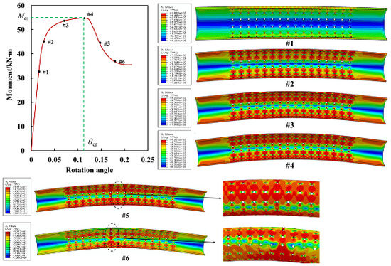
Figure 15.
Moment versus rotation angle and stress contour of screen pipes.
Meanwhile, the deformation at the middle position and the area around the hole was significant, which were the main areas of concern. Therefore, the ovality, stress, and strain at the middle position and area around the hole are discussed in detail. Figure 11a shows the middle and hole sections, and Figure 16 shows the ovality curve with the rotation angles of planes 1 and 2. As shown in Figure 16, the change in ovality with the rotation angle could be divided into three stages. In the first stage, when θ < θcr, the ovality difference between planes 1 and 2 was small as the rotation angle increased, indicating that the radial deformations of planes 1 and 2 were consistent. In the second stage, when θ > θcr, the ovality of plane 1 was gradually greater than that of plane 2 with an increase in θ. In the third stage, as θ increased, the ovality of planes 1 and 2 gradually increased, reaching a maximum and decreasing sharply. Meanwhile, the ovality of plane 2 was much smaller and reached the maximum value earlier than that of plane 1.
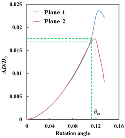
Figure 16.
Ovality versus rotation angle at middle position and hole position of screen pipes.
The node stress and element strain at the middle position and the area around the hole on the compression and tension sides of the screen are discussed in detail here. Figure 12 shows the selected elements and nodes, and Figure 17 shows the element strain and node stress at the middle position on the compression and tensile side. As shown in Figure 17a, when θ < 0.022, the stress difference of different nodes was small under the same θ. When 0.022 < θ < θcr, the stress first increased and then decreased as the node position was closer to the middle position of the screen pipe, and the stresses on both sides were more significant than that in the middle position under the same θ. When θ > θcr, the stress values at different locations fluctuated. Concerning the element strain, as shown in Figure 17b, the strain difference of the elements at different positions was small under the same θ. When 0.045 < θ < 0.127, the strains of the elements on both sides were more significant than that of the middle elements under the same θ. However, when θ > 0.127, the situation was reversed.
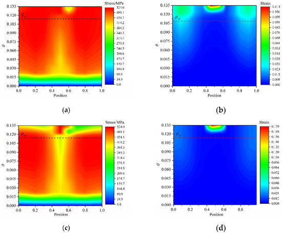
Figure 17.
(a,b) stress and strain on the compression side of screen pipe at middle position; (c,d) stress and strain on the tension side of screen pipe at middle position.
Figure 17c,d shows the node stress and element strain in the middle of the screen pipe at the tension side. The observations were similar to those on the compression side and will not be repeated here. Compared to the first two screen pipe deformation patterns, the strain values on the compression and tension sides of the middle position of pattern-3 were small. The difference between them was also small, indicating that the deformation at the middle position was small during the screen pipe bending process.
Figure 18a,b shows the node stress and element strain on the tension and compression sides of the hole. Figure 18a shows the node stress around the hole on the compression side. When θ < 0.022, the stress difference of different nodes was small under the same θ. When 0.022 < θ < 0.06, the stress first increased and then decreased as the node position was closer to the middle position of the hole. When θ > 0.06, the stress of the middle nodes of the hole was greater than that of the nodes on both sides. Figure 18b shows the element strain around the hole on the compression side. When θ < 0.03, the stress difference of different nodes was small under the same θ. When θ > 0.03, the element strains on both sides of the hole were more significant than that in the middle position. As the element position was closer to the middle of the hole, the element strain first increased and then decreased.
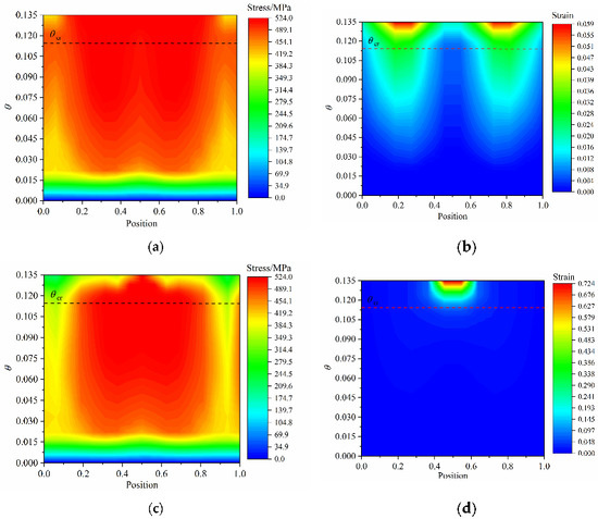
Figure 18.
(a,b) stress and strain on the compression side of screen pipe at holes position; (c,d) stress and strain on the tension side of screen pipe at holes position.
Figure 18c,d shows the node stress and element strain on the tension side of the hole position. The node stress at the hole position on the tension side was similar to that on the compression side and will not be repeated here. Concerning the element strain on the tension side, when θ < θcr, the strain difference of the different elements was small under the same rotation angle. When θ > θcr, the strain of the central elements of the screen hole was much larger than those of the elements on both sides. Comparing the strain at the hole position on the tension and compression sides, the maximum strain on the tension side was 0.724, which was much greater than the maximum strain of 0.059 on the compression side, indicating that the deformation at the hole position of the tension side was significant compared to that of the compression side, resulting in the plastic deformation of the screen pipe at the tension side.
Comparing the element strain results at the middle position of the screen pipe and hole position, when θ > θcr, the strain and, consequently, the deformation at the hole position on the tension side were much larger than those at the middle position of the screen pipe. As a result, deformation and yielding occurred from the hole position on the tension side of the screen pipe, which evolved into a fracture, whereas the deformation in the middle position of the screen pipe was small.
3. Influence of Different Parameters on the Ultimate Moment of Screen Pipes
The deformation patterns of screen pipes were different under different hole distribution parameters. However, when the moment was less than the ultimate moment, the change law of the rotation angle-moment is similar under different deformation patterns according to the above analysis. The screen tube’s ultimate moment was the field’s main parameter of interest. Therefore, the influence of different hole and screen pipe parameters on the ultimate moment of the screen pipe was analyzed. The selection of the parameters is shown in Table 1.
3.1. Effect of Diameter and Diameter-to-Thickness Ratio on the Ultimate Moment of Screen Pipes
The parameters N1 and N2 were 12 and 20. The other parameters were shown in Table 2. The effects of different hole diameters and D/t values on the ultimate bending moment of the screen pipe were analyzed, and the results were shown in Table 2. As shown in Table 2, as the hole diameter increased, the ultimate moment of the screen pipes with different D/t values gradually decreased, and the ultimate moment of the screen pipe with D/t = 19 was the largest with the same hole diameter. This is because the outer diameter of the screen pipe is inconsistent. According to the formula for calculating the ultimate bending moment of the complete pipe [34], the ultimate bending moment of the complete pipe is related to D and t. D significantly impacts the ultimate bending moment of the complete pipe. In addition, with an increase in the hole diameter, the ultimate moment of the screen pipe with D/t = 17, D/t = 19, and D/t = 23 decreased by 36.8%, 21.2%, and 26.3%, respectively, compared to the ultimate moment of the screen tube with a hole diameter of 6.35 mm.
Table 2.
Effect of D/t and hole diameter on ultimate moment of screen pipes.
3.2. Effect of Diameter-to-Thickness Ratio and Number of Axial Holes on the Ultimate Moment of Screen Pipes
The parament N1 and d were 12 and 9.5 mm. The parameters were shown in Table 3. The effects of the different number of axial holes and D/t values on the ultimate moment of the screen pipes were analyzed, and the results are shown in Table 3. As shown in Table 3, as the number of axial holes increased, the ultimate moment of the screen tubes with different D/t values gradually decreased. The ultimate moment of the screen pipe with D/t = 19 was the largest with the same number of axial holes. In addition, the number of axial holes slightly affected the screen pipes’ moment. Compared to the ultimate moment of the screen pipes with eight axial holes, the reductions of the D/t = 17, D/t = 19, D/t = 23 values were 2.2%, 6.4%, and 4.7%, respectively.
Table 3.
Effect of D/t and axial holes number on ultimate moment of screen pipes.
3.3. Effect of Diameter-to-Thickness Ratio and Number of Circumferential Holes on the Ultimate Moment of Screen Pipes
The parament N2 and d were 12 and 9.5 mm. The parameters were shown in Table 4. The effects of the different number of circumferential holes and D/t values on the ultimate moment of the screen pipes were analyzed, and the results are shown in Table 4. As shown in Table 4, the ultimate moment of the screen tubes with different D/t values gradually decreased as the number of circumferential holes increased. The ultimate moment of the screen pipes with D/t = 19 was the largest with the same number of circumferential holes. Compared to the axial holes’ effect on the screen pipes’ ultimate moment, the number of circumferential holes had a significant influence on the ultimate moment of the screen pipe. The reductions of the D/t = 17, D/t = 19, and D/t = 23 values were 28.4%, 15.4%, and 20.5%, respectively, compared to the ultimate moment of the screen pipes with four circumferential holes.
Table 4.
Effect of D/t and circumferential holes on ultimate moment of screen pipes.
3.4. Effect of Diameter and Number of Axial Holes on the Ultimate Moment of Screen Pipes
The number of circumferential holes and D/t of the screen pipes were 12 and 19, respectively, and the hole diameters were 6.35, 9.5, 12.7, 14.0, and 16.0 mm. The numbers of axial holes were 16, 20, and 24. The effects of the different number of axial holes and diameters on the ultimate moment of the screen pipes were analyzed, and the results are shown in Table 5. As shown in Table 5, the ultimate moment of the screen pipes with different numbers of axial holes gradually decreased as the diameter increased. Under the same diameter, as the number of axial holes increased, the ultimate moment of the screen pipes decreased. With an increase in the hole diameter, the ultimate moment of the screen pipe with 16, 20, and 24 axial holes decreased by 21.2%, 21.2%, and 21.9%, respectively, compared to the ultimate moment of the screen tube with a hole diameter of 6.35 mm.
Table 5.
Effect of diameter and axail holes number on ultimate moment of screen pipes.
3.5. Effect of Diameter and Number of Circumferential Holes on the Ultimate Moment of Screen Pipes
The number of axial holes and D/t of the screen pipes were 16 and 23, respectively, and the hole diameters were 6.35, 9.5, 12.7, 14.0, and 16.0 mm, respectively. The numbers of circumferential holes were 8, 12, and 16. The effects of the different number of circumferential holes and diameters on the ultimate moment of the screen pipes were analyzed, and the results are shown in Table 6. As the diameter increased, the screen pipes’ ultimate moment under different circumferential holes gradually decreased. For the same diameter, the greater the number of circumferential holes, the smaller the ultimate moment of the screen and the more significant the reduction in the ultimate moment. Compared to the ultimate moment of the screen pipe with a diameter of 6.35 mm, the ultimate moment values of the screen pipe with eight, 12, and 16 circumferential holes were reduced by 15.1%, 26.5%, and 42.9%, respectively. Compared to the effects of the axial holes on the ultimate moment, the effects of the circumferential holes were more significant.
Table 6.
Effect of diameter and circumferential holes number on ultimate moment of screen pipes.
4. The Ultimate Moment Formula of Screen Pipes
A simplified calculation formula was established to simplify the calculation of the ultimate bending moment of the screen pipe under pure bending and facilitate its field application. It was assumed that the ultimate moment of the screen pipe was related to the ultimate moment of the complete casing before perforation and the hole arrangement parameters (d, l, c), which could be expressed as the following relationship:
where U is the ultimate moment coefficient of the screen pipe, dimensionless, Mb the plastic ultimate bending moment the screen pipe, N∙m, Mi the plastic ultimate bending moment of the complete casing, which can be calculated using the formula in the literature [34], N∙m; d the diameter, mm; l the axial hole spacing, mm; c the circumferential hole spacing, mm; D the outer diameter of the screen pipe, mm; t the wall thickness, mm; and N the number of circumferential holes. γ was specified minimum yield strength.
Through fitting with the numerical simulation data, the relationship between U, d, c, and l was obtained, as shown in Figure 19. Thus, the dimensionless parameters d/c and d/l were introduced, and Equation (1) is expressed as:
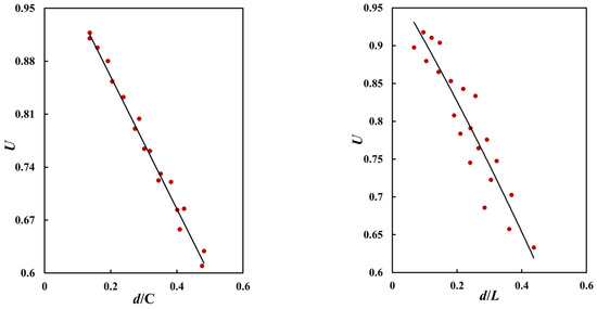
Figure 19.
The relationship between U and d, l, c.
Assuming that the F function in Equation (4) could be expanded into a power series, Equation (4) could be expressed as:
Considering that the ultimate moment of the screen pipe was less than that of the casing before perforation, U ≤ 1 when n = 0 and B0 = 1. Ignoring the influence of higher-order terms in Equation (5) [35,36,37], it was approximately expressed as:
The numerical simulation results were used to fit Equation (6) and determine the parameter values in the formula. It was given by:
Figure 20 shows the comparison between the numerical simulation results and the calculation results obtained using Equation (7). As shown in Figure 20, the difference between the FEM results and formula calculation results had a range of −0.04–4.79%, and the average error is 1.26%. Therefore, the established formulas can accurately reflect the numerical results.
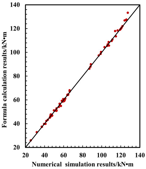
Figure 20.
Comparison of numerical simulation and formula calculation results.
Due to the lack of literature results on the bending test of screen pipe, the eight groups of screen pipe finite element results shown in Table 7 are used to verify the accuracy of the established formulas. Those results were outside the fitting data of the formulas. As shown in Table 7, the minimum difference between the numerical simulation and the formula results was 0.02%, and the maximum error was 6.16%. The average error for the FEM results of the five groups of screen pipes was 3.25%. Therefore, the established empirical formula can accurately calculate the ultimate moment of screen pipe under bending load.
Table 7.
Ultimate moment comparison between numerical and formula results.
5. Conclusions
The finite element model of a screen pipe with a parallel hole arrangement under pure bending was defined based on ABAQUS and Python script. The deformation patterns and ultimate moment of screen pipes with different parameters were analyzed. Three deformation patterns were identified and discussed in detail. An empirical formula of the ultimate moment of screen pipes was proposed. The main conclusions are summarized as follows:
(1) The deformation patterns of screen pipes could be divided into three categories under a bending load: In Pattern-1, the screen pipes buckled from the middle position, and the area around the holes did not fracture. In Pattern-2, the screen pipes first buckled from the middle position. As the bending load increased, plastic deformation appeared around the holes, and fracture occurred. In Pattern-3, plastic deformation appeared around the hole area, and fracture occurred. However, the deformation around the middle of the screen pipes was small.
(2) The proposed empirical formula could accurately calculate the ultimate moment of screen pipe under bending load, and the average difference between the empirical formula and numerical simulation results was 3.25%.
(3) With an increase in the diameter and number of circumferential and axial holes, the ultimate moment of the screen pipe gradually decreased, and the circumferential holes had a more significant effect on the ultimate moment than the axial holes.
Author Contributions
Numerical simulation model, Y.P. and G.F.; Python Script, Y.P.; Formal analysis, B.S. and S.F.E.; investigation, X.S.; data curation, J.C.; writing, Y.P.; review and editing, G.F.; supervision, B.S. and S.F.E.; funding acquisition, B.S. and S.F.E. All authors have read and agreed to the published version of the manuscript.
Funding
This work was supported by the National Natural Science Foundation of China [51890914, 51709269, 52104056], the National Ministry of Industry and Information Technology Innovation Special Project-Engineering Demonstration Application of Subsea Oil and Gas Production System-Subject 4: Research on Subsea Christmas Tree and Wellhead Offshore Testing Technology [MC-201901-S01-04]. The last author, Estefen, acknowledges the support from the Brazilian Research Council—CNPQ [303182/2022-9].
Institutional Review Board Statement
Not applicable.
Informed Consent Statement
Not applicable.
Data Availability Statement
Not applicable.
Conflicts of Interest
The authors declare no conflict of interest.
References
- Ma, C.; Deng, J.; Dong, X. A new laboratory protocol to study the plugging and sand control performance of sand control screens. J. Petrol. Sci. Eng. 2020, 184, 106548. [Google Scholar] [CrossRef]
- Dong, C.; Gao, K.; Dong, S. A new integrated method for comprehensive performance of mechanical sand control screens testing and evaluation. J. Petrol. Sci. Eng. 2017, 158, 775–783. [Google Scholar] [CrossRef]
- Galkin, V.; Martyushev, D.; Ponomareva, I. Developing features of the near-bottom hole zones in productive formations at fields with high gas saturation of formation oil. J. Min. Inst. 2021, 249, 386–392. [Google Scholar] [CrossRef]
- Ranjith, P.; Perera, M.; Perera, W. Effective parameters for sand production in unconsolidated formations: An experimental study. J. Petrol. Sci. Eng. 2013, 105, 34–42. [Google Scholar] [CrossRef]
- Mahmud, H.; Leong, H.; Lestariono, Y. Sand production: A smart control framework for risk mitigation. Petroleum 2020, 6, 1–13. [Google Scholar] [CrossRef]
- Wang, D.-B.; Zhou, F.-J.; Li, Y.-P. Numerical simulation of fracture propagation in Russia carbonate reservoirs during refracturing. Petrol. Sci. 2022, 19, 2781–2795. [Google Scholar] [CrossRef]
- Kuriyama, Y.; Tsukano, Y.; Mimaki, T. Effect of wear and bending on casing collapse strength. In Proceedings of the SPE Annual Technical Conference and Exhibition, Washington, DC, USA, 4–7 October 1992; OnePetro: Richardson, TX, USA, 1992. [Google Scholar]
- Zhang, J.; Yin, G.; Fan, Y. The helical buckling and extended reach limit of coiled tubing with initial bending curvature in horizontal wellbores. J. Petrol. Sci. Eng. 2021, 200, 108398. [Google Scholar] [CrossRef]
- Wang, J.D.; Dou, Y.; Cao, Y. Collapsing Strength Analysis of Bending Part Casing in Horizontal Wells under Three-point Bending. In Applied Mechanics and Materials; Trans Tech Publications Ltd.: Stafa-Zurich, Switzerland, 2015; Volume 713, pp. 57–60. [Google Scholar]
- Wu, J. Drill-pipe bending and fatigue in rotary drilling of horizontal wells. In Proceedings of the SPE Eastern Regional Meeting, Columbus, OH, USA, 23–25 October 1996. [Google Scholar]
- Chen, Y.; Zhang, J.; Zhang, H. Ultimate bending capacity of strain hardening steel pipes. China Ocean Eng. 2016, 30, 231–241. [Google Scholar] [CrossRef]
- Sadowski, A.; Rotter, J. Solid or shell finite elements to model thick cylindrical tubes and shells under global bending. Int. J. Mech. Sci. 2013, 74, 143–153. [Google Scholar] [CrossRef]
- Chen, Y.; Zhang, H.; Zhang, J. Residual bending capacity for pipelines with corrosion defects. J. Loss. Prevent. Proc. 2014, 32, 70–77. [Google Scholar] [CrossRef]
- Kshitij, K.; Gerasimidis, S. Instability of thin steel cylindrical shells under bending. Thin-Walled Struct. 2019, 137, 151–166. [Google Scholar]
- Erling, Ø.; Jayadevan, K.; Thaulow, C. Fracture response of pipelines subject to large plastic deformation under bending. Int. J. Press. Vessel. Pip. 2005, 82, 201–215. [Google Scholar]
- Jayadevan, K.; Erling, Ø.; Thaulow, C. Fracture response of pipelines subjected to large plastic deformation under tension. Int. J. Press. Vessel. Pip. 2004, 81, 771–783. [Google Scholar] [CrossRef]
- Chegeni, B.; Sachith, J.; Sreekanta, D. Effect of corrosion on thin-walled pipes under combined internal pressure and bending. Thin-Walled Struct. 2019, 143, 106211–106218. [Google Scholar] [CrossRef]
- Hieu, C.; Le, T.; Bui, N. An empirical model for bending capacity of defected pipe combined with axial load. Int. J. Press. Vessel. Pip. 2021, 191, 104368. [Google Scholar]
- Es, S.; Gresnigt, A.; Vasilikis, D. Ultimate bending capacity of spiral-welded steel tubes—Part I: Experiments. Thin-Walled Struct. 2016, 102, 286–304. [Google Scholar]
- Es, S.; Gresnigt, A.; Vasilikis, D. Ultimate bending capacity of spiral-welded steel tubes—Part II: Predictions. Thin-Walled Struct. 2016, 102, 305–319. [Google Scholar]
- Limam, A.; Lee, L.; Corona, E. Inelastic wrinkling and collapse of tubes under combined bending and internal pressure. Int. J. Mech. Sci. 2010, 52, 637–647. [Google Scholar] [CrossRef]
- Limam, A.; Lee, L.; Kyriakides, S. On the collapse of dented tubes under combined bending and internal pressure. Int. J. Mech. Sci. 2012, 55, 1–12. [Google Scholar] [CrossRef]
- Fu, G.; Peng, Y.; Sun, B. Collapse pressure calculation of sand control screen tube under combined external pressure and bending. J. China Univ. Pet. (Ed. Nat. Sci.) 2021, 45, 78–86. (In Chinese) [Google Scholar]
- Peng, Y. Research on the Influence of Hole Distribution Parameters on the Strength Performance of Sand Control Screen. Master’s Thesis, China University of Petroleum, Beijing, China, 2020. (In Chinese). [Google Scholar]
- Kyriakides, S.; Corona, E. Localization and propagation of curvature under pure bending in steel tubes with Lüders bands. Int. J. Solids Struct. 2008, 45, 3074–3087. [Google Scholar] [CrossRef]
- Karampour, H.; Albermani, F. Experimental and numerical investigations of buckle interaction in subsea pipelines. Eng. Struct. 2014, 66, 81–88. [Google Scholar] [CrossRef]
- Karampour, H. Effect of proximity of imperfections on buckle interaction in deep subsea pipelines. Mar. Struct. 2018, 59, 444–457. [Google Scholar] [CrossRef]
- Arjomandi, K.; Taheri, F. Bending capacity of sandwich pipes. Ocean Eng. 2012, 48, 17–31. [Google Scholar] [CrossRef]
- Binazir, A.; Karampour, H.; Sadowski, A.J.; Gilbert, B.P. Pure bending of pipe-in-pipe systems. Thin-Walled Struct. 2019, 145, 106381. [Google Scholar] [CrossRef]
- Lyu, Y.; Li, G.Q.; Cao, K. Bending behavior of splice connection for corner-supported steel modular buildings. Eng. Struct. 2022, 250, 113460. [Google Scholar] [CrossRef]
- Yong, B.; Tang, J.; Xu, W. Collapse of reinforced thermoplastic pipe (RTP) under combined external pressure and bending moment. Ocean Eng. 2015, 94, 10–18. [Google Scholar]
- Luo, L.; Zhao, M. The Secondary Development of ABAQUS by using Python and the Application of the Advanced GA. Phys. Procedia 2011, 22, 68–73. [Google Scholar] [CrossRef]
- He, T.; Duan, M.; An, C. Prediction of the collapse pressure for thick-walled pipes under external pressure. Appl. Ocean Res. 2014, 47, 199–203. [Google Scholar] [CrossRef]
- SØren, R.; Bai, Y. Bending Moment Capacity of Pipes. J. Offshore Mech. Arct. Eng. 2000, 4, 243–252. [Google Scholar]
- Kyriakides, S.; Lee, L. On the arresting efficiency of slip-on buckle arrestors for offshore pipelines. Int. J. Mech. Sci. 2004, 7, 1035–1055. [Google Scholar]
- Fu, G.; Li, M.; Yang, J. A simplified equation for the collapse pressure of sandwich pipes with different core materials. Ocean Eng. 2022, 254, 111292. [Google Scholar] [CrossRef]
- Li, G.; Gong, S. Buckle propagation of pipe-in-pipe systems under external pressure. Eng. Struct. 2015, 84, 207–222. [Google Scholar]
Disclaimer/Publisher’s Note: The statements, opinions and data contained in all publications are solely those of the individual author(s) and contributor(s) and not of MDPI and/or the editor(s). MDPI and/or the editor(s) disclaim responsibility for any injury to people or property resulting from any ideas, methods, instructions or products referred to in the content. |
© 2023 by the authors. Licensee MDPI, Basel, Switzerland. This article is an open access article distributed under the terms and conditions of the Creative Commons Attribution (CC BY) license (https://creativecommons.org/licenses/by/4.0/).