
Coupling of Finite Element Method and Peridynamics to Simulate Ship-Ice Interaction

Abstract
1. Introduction
2. Peridynamics Framework
3. Coupling of PD-FEM
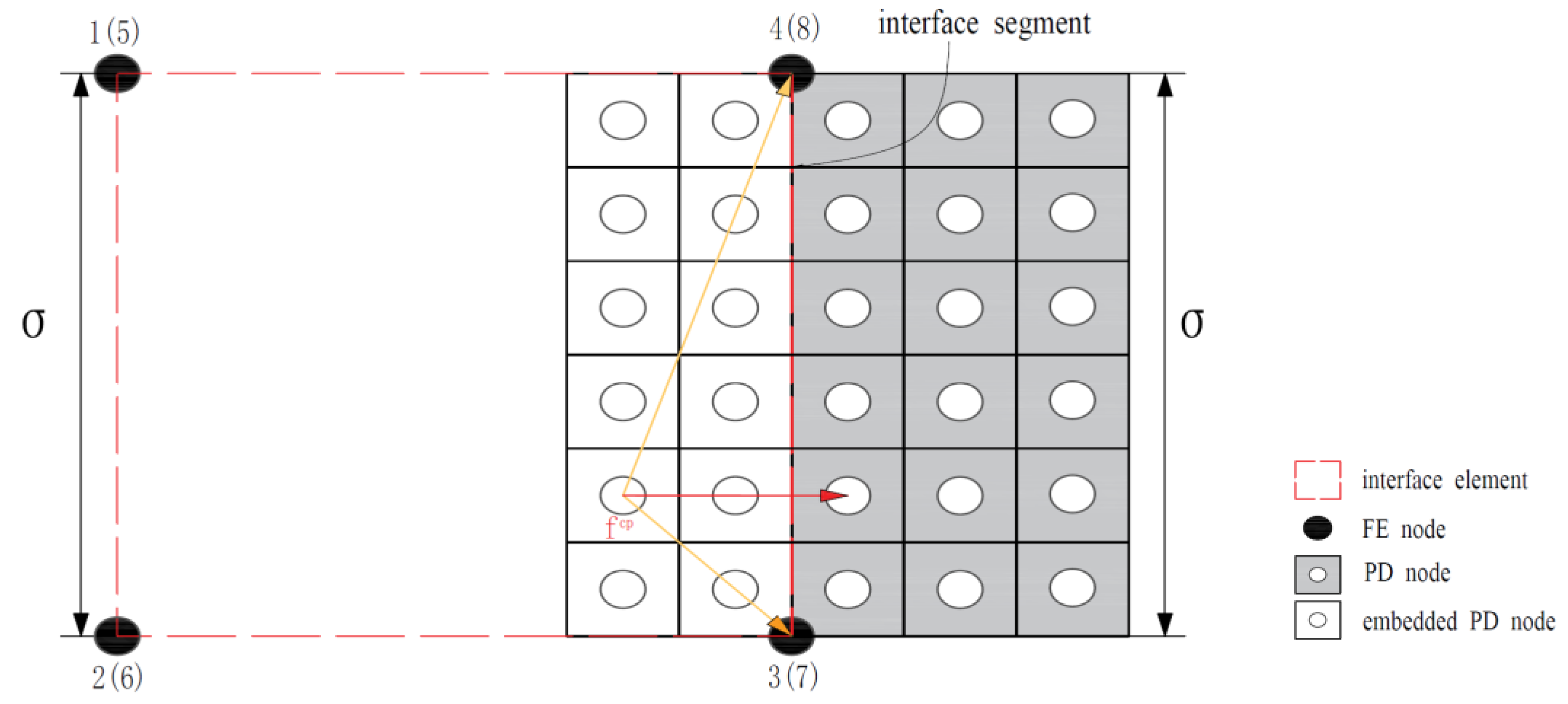
3.1. Coupling Scheme
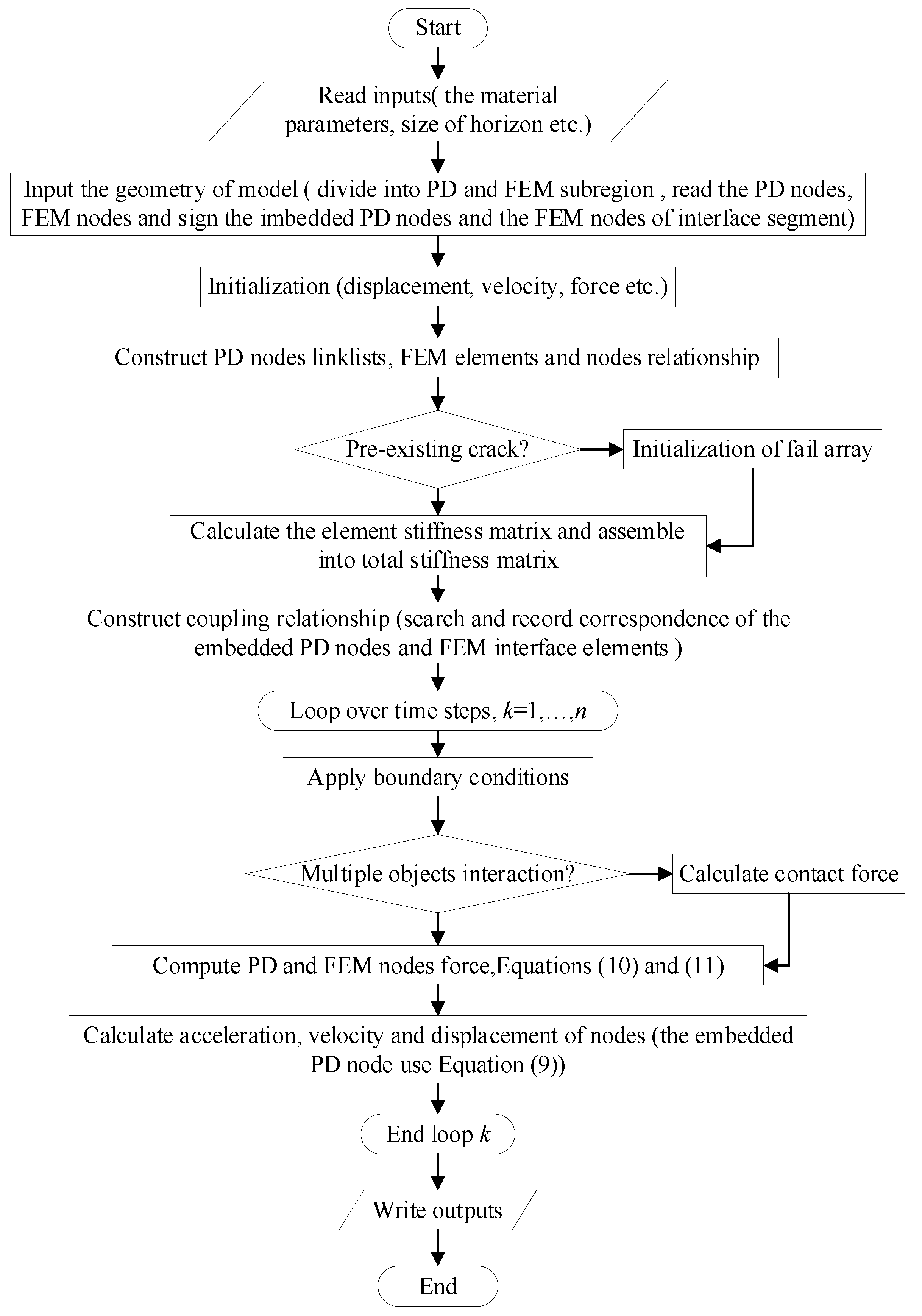
3.2. Numerical Implementation
4. Validation of PD-FEM Coupling Approach
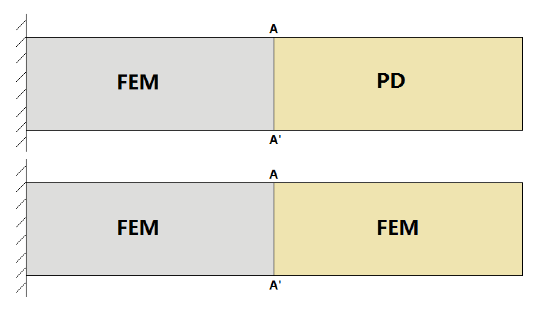
4.1. Bending Deformation of Cantilever Beam

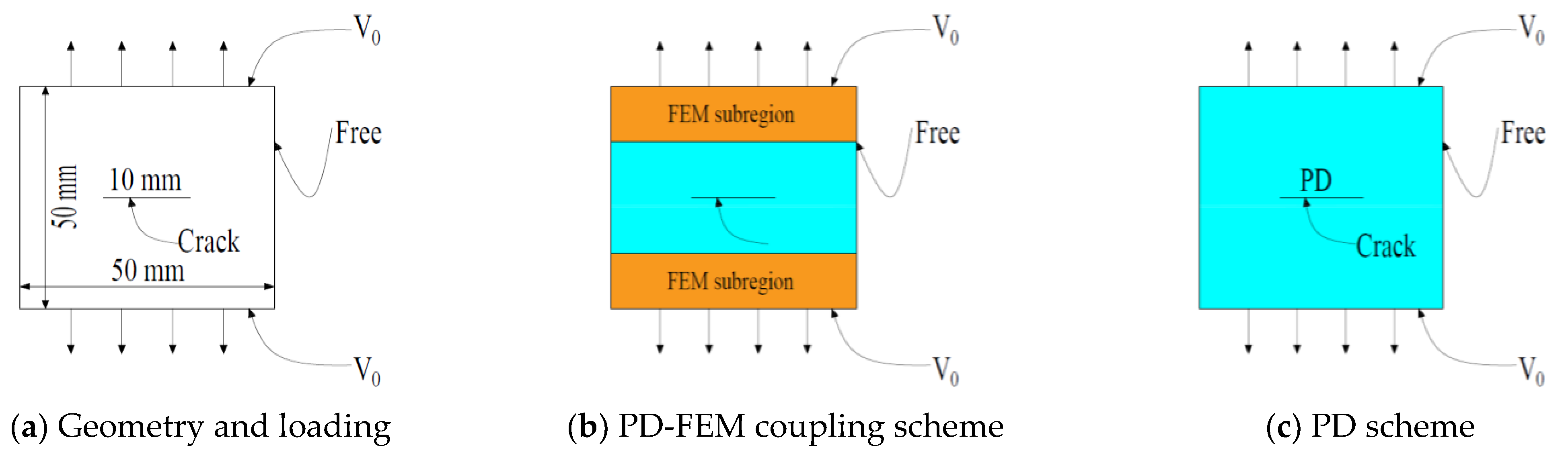
4.2. Failure of 2D Plate with Central Crack
5. PD-FEM Simulation of Icebreaker Navigation in Ice Level
5.1. Numerical Simulation
5.1.1. Ice Constitutive Model and Failure Criterion
5.1.2. The Gravity and Buoyancy Model of Ice
5.1.3. Ship-Ice Contact Model
5.1.4. Numerical Model
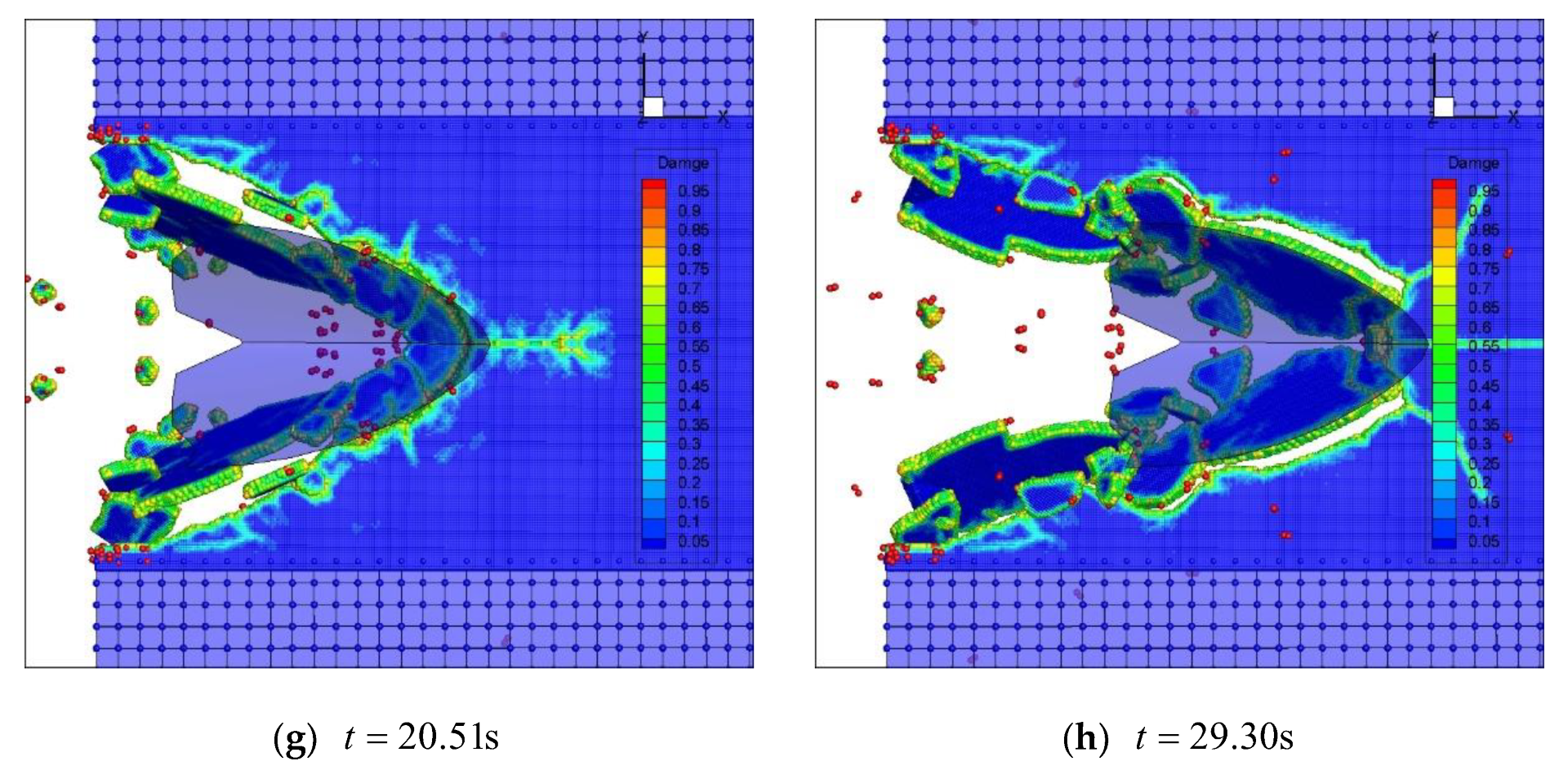
5.1.5. Numerical Result and Discussion
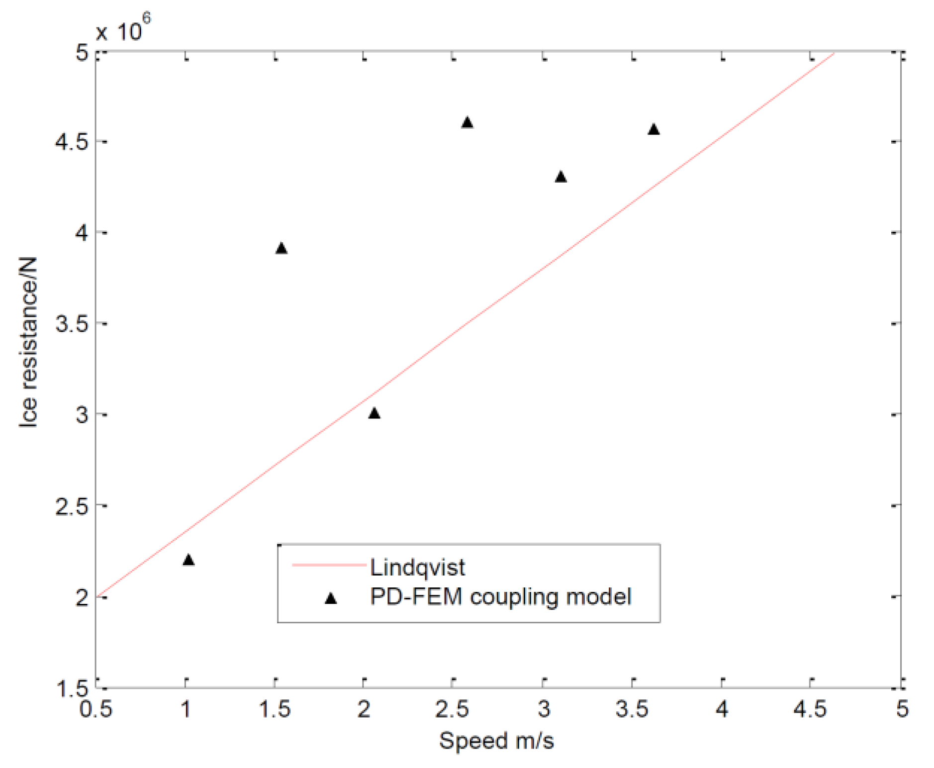
5.2. Influence of Ship Speed on Ice Load
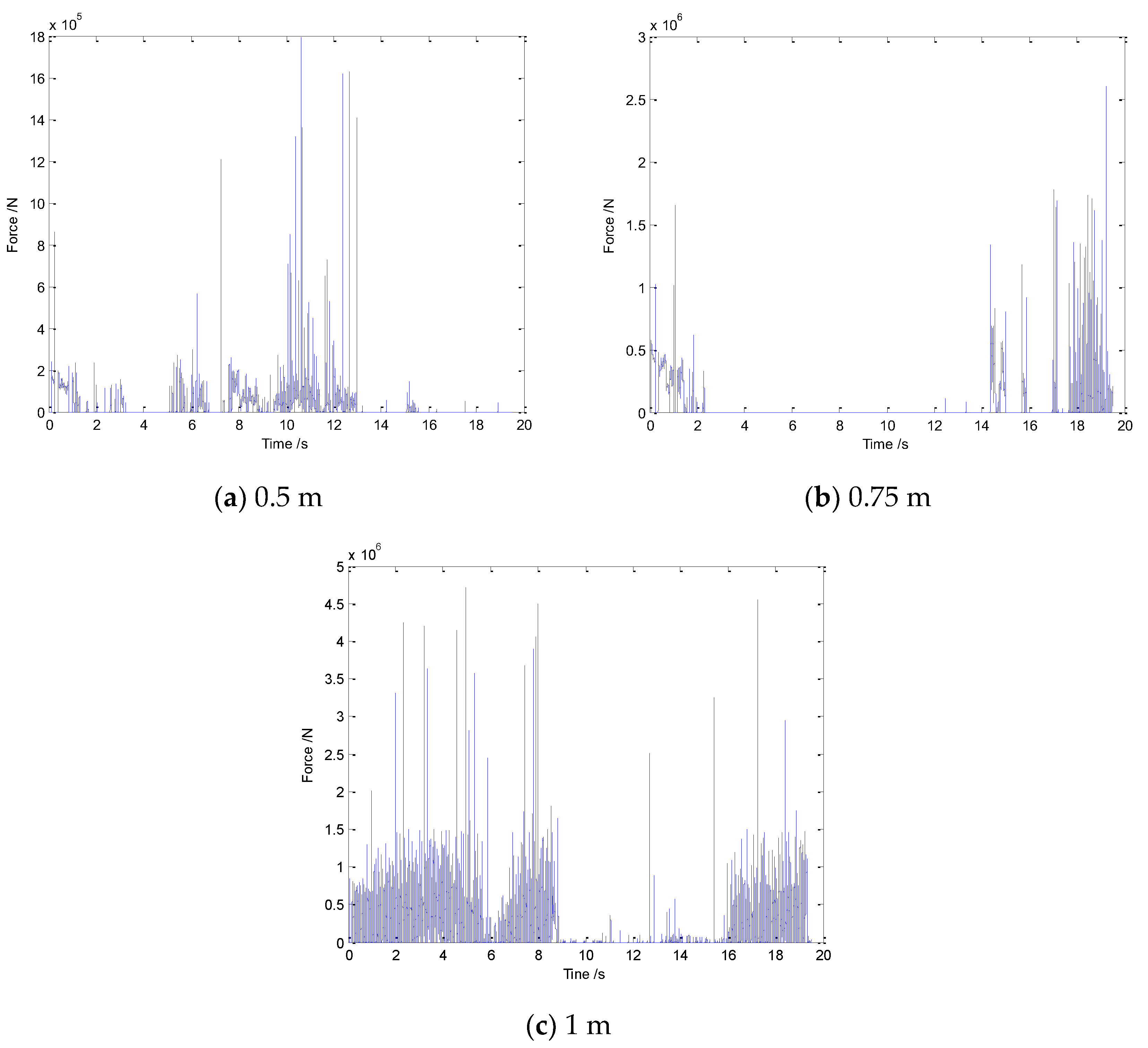
5.3. Influence of Ice Thickness on Ice Load
6. Conclusions
- (1)
- The PD-FEM coupling model can successfully simulate the generation and propagation of radial and circular cracks in level ice, as well as the phenomena of wedge ice shedding, broken ice flipping, and ice cleaning of the channel during the ice-breaking process.
- (2)
- Compared with bond-based peridynamics, the PD-FEM coupling model has better computational efficiency, and can effectively suppress the boundary effect when the level ice is failure.
- (3)
- The ice load obtained from the PD-FEM coupling model is in good agreement with that obtained from Lindqvist’s empirical formula.
Author Contributions
Funding
Institutional Review Board Statement
Informed Consent Statement
Data Availability Statement
Conflicts of Interest
References
- Xue, Y.; Liu, R.; Li, Z.; Han, D. A review for numerical simulation methods of ship—Ice interaction. Ocean Eng. 2020, 215, 107853. [Google Scholar] [CrossRef]
- Kujala, P.; Goerlandt, F.; Way, B.; Smith, D.; Yang, M.; Khan, F.; Veitch, B. Review of risk-based design for ice-class ships. Mar. Struct. 2019, 63, 181–195. [Google Scholar] [CrossRef]
- Lubbad, R.; Løset, S. A numerical model for real-time simulation of ship—Ice interaction. Cold Reg. Sci. Technol. 2011, 65, 111–127. [Google Scholar] [CrossRef]
- Raza, N.; Van Der Berg, M.; Lu, W.; Lubbad, R. Analysis of oden icebreaker performance in level ice using simulator for arctic marine structures (SAMS). In Proceedings of the International Conference on Port and Ocean Engineering under Arctic Conditions, Delft, The Netherlands, 9–13 June 2019. [Google Scholar]
- Yu, Z.; Lu, W.; Van Den Berg, M.; Amdahl, J.; Løset, S. Glacial ice impacts: Part II: Damage assessment and ice-structure interactions in accidental limit states (ALS). Mar. Struct. 2021, 75, 102889. [Google Scholar] [CrossRef]
- Sodhi, D.S.; Morris, C.E. Characteristic frequency of force variations in continuous crushing of sheet ice against rigid cylindrical structures. Cold Reg. Sci. Technol. 1986, 12, 1–12. [Google Scholar] [CrossRef]
- Määttänen, M.; Marjavaara, P.; Saarinen, S.; Laakso, M. Ice crushing tests with variable structural flexibility. Cold Reg. Sci. Technol. 2011, 67, 120–128. [Google Scholar] [CrossRef]
- Sun, J.; Huang, Y. Investigations on the ship-ice impact: Part 1. Experimental methodologies. Mar. Struct. 2020, 72, 102772. [Google Scholar] [CrossRef]
- Sun, J.; Huang, Y. Investigations on the ship-ice impact: Part 2. spatial and temporal variations of ice load. Ocean Eng. 2021, 240, 109686. [Google Scholar] [CrossRef]
- Li, F.; Kõrgesaar, M.; Kujala, P.; Goerlandt, F. Finite element based meta-modeling of ship-ice interaction at shoulder and midship areas for ship performance simulation. Mar. Struct. 2020, 71, 102736. [Google Scholar] [CrossRef]
- Jou, O.; Celigueta, M.A.; Latorre, S.; Arrufat, F.; Oñate, E. A bonded discrete element method for modeling ship—Ice interactions in broken and unbroken sea ice fields. Comput. Part. Mech. 2019, 6, 739–765. [Google Scholar] [CrossRef]
- Aksnes, V. A simplified interaction model for moored ships in level ice. Cold Reg. Sci. Technol. 2010, 63, 29–39. [Google Scholar] [CrossRef]
- Huang, L.; Tuhkuri, J.; Igrec, B.; Li, M.; Stagonas, D.; Toffoli, A.; Cardiff, P.; Thomas, G. Ship resistance when operating in floating ice floes: A combined CFD&DEM approach. Mar. Struct. 2020, 74, 102817. [Google Scholar]
- Luo, W.; Jiang, D.; Wu, T.; Guo, C.; Wang, C.; Deng, R.; Dai, S. Numerical simulation of an ice-strengthened bulk carrier in brash ice channel. Ocean Eng. 2020, 196, 106830. [Google Scholar] [CrossRef]
- Kim, J.-H.; Kim, Y.; Kim, H.-S.; Jeong, S.-Y. Numerical simulation of ice impacts on ship hulls in broken ice fields. Ocean Eng. 2019, 182, 211–221. [Google Scholar] [CrossRef]
- Ni, B.-Y.; Chen, Z.-W.; Zhong, K.; Li, X.-A.; Xue, Y.-Z. Numerical simulation of a polar ship moving in level ice based on a one-way coupling method. J. Mar. Sci. Eng. 2020, 8, 692. [Google Scholar] [CrossRef]
- Wang, B.; Yu, H.-C.; Basu, R. Ship and ice collision modeling and strength evaluation of LNG ship structure. In Proceedings of the International Conference on Offshore Mechanics and Arctic Engineering, Estoril, Portugal, 15–20 June 2008; pp. 911–918. [Google Scholar]
- Herrnring, H.; Ehlers, S. A finite element model for compressive ice loads based on a Mohr-Coulomb material and the node splitting technique. J. Offshore Mech. Arct. Eng. 2022, 144, 021601. [Google Scholar] [CrossRef]
- Liu, L.; Ji, S. Comparison of sphere-based and dilated-polyhedron-based discrete element methods for the analysis of ship—Ice interactions in level ice. Ocean Eng. 2022, 244, 110364. [Google Scholar] [CrossRef]
- Tang, X.; Zou, M.; Zou, Z.; Li, Z.; Zou, L. A parametric study on the ice resistance of a ship sailing in pack ice based on CFD-DEM method. Ocean Eng. 2022, 265, 112563. [Google Scholar] [CrossRef]
- Zhang, J.; Zhang, Y.; Shang, Y.; Jin, Q.; Zhang, L. CFD-DEM based full-scale ship-ice interaction research under FSICR ice condition in restricted brash ice channel. Cold Reg. Sci. Technol. 2022, 194, 103454. [Google Scholar] [CrossRef]
- Zou, M.; Tang, X.-J.; Zou, L.; Zou, Z.-J. Numerical Simulation of Ship-Ice Interaction in Pack Ice Area Based on CFD-DEM Coupling Method. In Proceedings of the International Conference on Offshore Mechanics and Arctic Engineering, Hamburg, Germany, 5–10 June 2022; p. V006T007A027. [Google Scholar]
- Zhang, N.; Zheng, X.; Ma, Q.; Hu, Z. A numerical study on ice failure process and ice-ship interactions by Smoothed Particle Hydrodynamics. Int. J. Nav. Archit. Ocean Eng. 2019, 11, 796–808. [Google Scholar] [CrossRef]
- Chen, Z.; He, Y.; Gu, Y.; Su, B.; Ren, Y.; Liu, Y. A novel method for numerical simulation of the interaction between level ice and marine structures. J. Mar. Sci. Technol. 2021, 26, 1170–1183. [Google Scholar] [CrossRef]
- Herrnring, H.; Kellner, L.; Kubiczek, J.M.; Ehlers, S. Simulation of Ice-Structure Interaction with CZM-Elements. In Proceedings of the 18th German LS-Dyna Forum, Bamberg, Germany, 24 October 2018; pp. 15–17. [Google Scholar]
- Zhang, J.; Liu, Z.; Ong, M.C.; Tang, W. Numerical simulations of the sliding impact between an ice floe and a ship hull structure in ABAQUS. Eng. Struct. 2022, 273, 115057. [Google Scholar] [CrossRef]
- Silling, S.A. Reformulation of elasticity theory for discontinuities and long-range forces. J. Mech. Phys. Solids 2000, 48, 175–209. [Google Scholar] [CrossRef]
- Xue, Y.; Liu, R.; Liu, Y.; Zeng, L.; Han, D. Numerical simulations of the ice load of a ship navigating in level ice using peridynamics. Comput. Model. Eng. 2019, 121, 523–550. [Google Scholar] [CrossRef]
- Yuan, Z.; Longbin, T.; Chao, W.; Liyu, Y.; Chunyu, G. Numerical study on dynamic icebreaking process of an icebreaker by ordinary state-based peridynamics and continuous contact detection algorithm. Ocean Eng. 2021, 233, 109148. [Google Scholar] [CrossRef]
- Liu, R.; Xue, Y.; Lu, X.; Cheng, W. Simulation of ship navigation in ice rubble based on peridynamics. Ocean Eng. 2018, 148, 286–298. [Google Scholar] [CrossRef]
- Liu, R.; Yan, J.; Li, S. Modeling and simulation of ice—Water interactions by coupling peridynamics with updated Lagrangian particle hydrodynamics. Comput. Part. Mech. 2020, 7, 241–255. [Google Scholar] [CrossRef]
- Ye, L.; Guo, C.; Wang, C.; Wang, C.; Chang, X. Peridynamic solution for submarine surfacing through ice. Ships Offshore Struct. 2020, 15, 535–549. [Google Scholar] [CrossRef]
- Liu, R.; Xue, Y.; Han, D.; Ni, B. Studies on model-scale ice using micro-potential-based peridynamics. Ocean Eng. 2021, 221, 108504. [Google Scholar] [CrossRef]
- Vazic, B.; Oterkus, E.; Oterkus, S. In-plane and out-of plane failure of an ice sheet using peridynamics. J. Mech. 2020, 36, 265–271. [Google Scholar] [CrossRef]
- Chunyu, G.; Kang, H.; Chao, W.; Liyu, Y.; Zeping, W. Numerical modelling of the dynamic ice-milling process and structural response of a propeller blade profile with state-based peridynamics. Ocean Eng. 2022, 264, 112457. [Google Scholar] [CrossRef]
- Vazic, B.; Oterkus, E.; Oterkus, S. Peridynamic approach for modelling ice-structure interactions. Trends Anal. Des. Mar. Struct. 2019, 55–60. [Google Scholar]
- Song, Y.; Yan, J.; Li, S.; Kang, Z. Peridynamic modeling and simulation of ice craters by impact. Comput. Model. Eng. Sci. 2019, 121, 465–492. [Google Scholar] [CrossRef]
- Macek, R.W.; Silling, S.A. Peridynamics via finite element analysis. Finite Elem. Anal. Des. 2007, 43, 1169–1178. [Google Scholar] [CrossRef]
- Liu, W.; Hong, J.-W. A coupling approach of discretized peridynamics with finite element method. Comput. Method Appl. M. 2012, 245, 163–175. [Google Scholar] [CrossRef]
- Lee, J.; Liu, W.; Hong, J.-W. Impact fracture analysis enhanced by contact of peridynamic and finite element formulations. Int. J. Impact Eng. 2016, 87, 108–119. [Google Scholar] [CrossRef]
- Silling, S.A.; Askari, E. A meshfree method based on the peridynamic model of solid mechanics. Comput. Struct. 2005, 83, 1526–1535. [Google Scholar] [CrossRef]
- Madenci, E.; Oterkus, E. Peridynamic theory. In Peridynamic Theory and Its Applications; Springer: Berlin/Heidelberg, Germany, 2014; pp. 19–43. [Google Scholar]
- Kilic, B.; Madenci, E. An adaptive dynamic relaxation method for quasi-static simulations using the peridynamic theory. Theor. Appl. Fract. Mech. 2010, 53, 194–204. [Google Scholar] [CrossRef]
- Knott, J.F. Fundamentals of Fracture Mechanics; Gruppo Italiano Frattura, 1973. [Google Scholar]
- Schulson, E.M. Brittle failure of ice. Eng. Fract. Mech. 2001, 68, 1839–1887. [Google Scholar] [CrossRef]


| PD-FEM | FEM | Errors | |
|---|---|---|---|
| Deflection | 8.0492 × 10⁻⁵ m | 8.19 × 10⁻⁵ m | 1.74% |
| Force | −0.6327 N | −0.64 N | 1.14% |
| Parameter | Variable | Value |
|---|---|---|
| Ship length | L | 166.0 m |
| Ship breadth | B | 22.6 m |
| Ship depth | D | 13.5 m |
| Bow length | l | 29.6 m |
| Bow breadth | b | 22.6 m |
| Draft | T | 8.0 m |
| Stem angle | α | 20° |
| Flooding angle | β | 24° |
| Ship-ice friction coefficient | μ | 0.15 |
| Parameter | Variable | Value |
|---|---|---|
| Young’s modulus | E | 6.83 GPa |
| Poisson’s ratio | ν | 0.25 |
| Bending strength | σf | 2.96 MPa |
| Fracture toughness | KI | 115 kNm−3/2 |
| Density | ρ | 894 kg/m3 |
| Area | A | 100 × 100 m2 |
| Thickness | h | 1.0 m |
| Item | PD-FEM | PD |
|---|---|---|
| Particle number | 187,840 | 654,400 |
| Element number | 1800 | 0 |
| Total time steps | 300,000 | 300,000 |
| Total CPU time | 52.32 h | 135.47 h |
| Method | 2 kn | 3 kn | 4 kn | 5 kn | 6 kn | 7 kn |
|---|---|---|---|---|---|---|
| Lindqvist | 2.370 × 10⁶ N | 2.743 × 10⁶ N | 3.120 × 10⁶ N | 3.490 × 10⁶ N | 3.863 × 10⁶ N | 4.237 × 10⁶ N |
| PD-FEM | 2.202 × 10⁶ N | 3.921 × 10⁶ N | 3.008 × 10⁶ N | 4.612 × 10⁶ N | 4.307 × 10⁶ N | 4.560 × 10⁶ N |
| Errors | 7.1% | 42.9% | 3.6% | 32.1% | 11.5% | 7.6% |
Disclaimer/Publisher’s Note: The statements, opinions and data contained in all publications are solely those of the individual author(s) and contributor(s) and not of MDPI and/or the editor(s). MDPI and/or the editor(s) disclaim responsibility for any injury to people or property resulting from any ideas, methods, instructions or products referred to in the content. |
© 2023 by the authors. Licensee MDPI, Basel, Switzerland. This article is an open access article distributed under the terms and conditions of the Creative Commons Attribution (CC BY) license (https://creativecommons.org/licenses/by/4.0/).
Share and Cite
Liu, R.; Xue, Y.; Lu, X. Coupling of Finite Element Method and Peridynamics to Simulate Ship-Ice Interaction. J. Mar. Sci. Eng. 2023, 11, 481. https://doi.org/10.3390/jmse11030481
Liu R, Xue Y, Lu X. Coupling of Finite Element Method and Peridynamics to Simulate Ship-Ice Interaction. Journal of Marine Science and Engineering. 2023; 11(3):481. https://doi.org/10.3390/jmse11030481
Chicago/Turabian StyleLiu, Renwei, Yanzhuo Xue, and Xikui Lu. 2023. "Coupling of Finite Element Method and Peridynamics to Simulate Ship-Ice Interaction" Journal of Marine Science and Engineering 11, no. 3: 481. https://doi.org/10.3390/jmse11030481
APA StyleLiu, R., Xue, Y., & Lu, X. (2023). Coupling of Finite Element Method and Peridynamics to Simulate Ship-Ice Interaction. Journal of Marine Science and Engineering, 11(3), 481. https://doi.org/10.3390/jmse11030481