Article

Stress–Strain Assessment of Honeycomb Sandwich Panel Subjected to Uniaxial Compressive Load

1
Department of Engineering, University of Messina, 98166 Messina, Italy
2
Centre for Marine Technology and Engineering (CENTEC), Technical University of Lisbon, Instituto Superior Técnico, 1049-001 Lisboa, Portugal
*
Author to whom correspondence should be addressed.
J. Mar. Sci. Eng. 2023, 11(2), 365; https://doi.org/10.3390/jmse11020365
Submission received: 30 December 2022 / Revised: 17 January 2023 / Accepted: 2 February 2023 / Published: 6 February 2023

Abstract

:
The ship hull structure is composed of plates and stiffened panels. Estimating the maximum load-carrying capacity, or the ultimate strength, of these structural components is fundamental. One of the main challenges nowadays is the implementation of new materials and technologies to enhance the structural integrity, economy, safety and environmentally friendly design of the ship’s hull structure. A new design solution may be represented by aluminium alloy honeycomb sandwich structures, both as plane panels or stiffened ones, which are characterised by excellent impact-absorption capabilities and a high stiffness-to-weight ratio. Still, their response to some conditions typical of ship structural design needs to be deeply investigated. Axial compressive loading is one of the most critical conditions that could impact the structural integrity of such light-weight solutions. Hence, the uniaxial compressive behaviour of aluminium honeycomb sandwich structures has to be deeply investigated to promote their integration in ship structural design. Within this context, the present work performs an experimental and numerical study of a honeycomb sandwich panel subjected to uniaxial compressive loads. The results will help develop models for predicting the uniaxial compressive load-carrying capacity of hybrid honeycomb sandwiches of aluminium alloy design.

1. Introduction

Rules and guidelines control ship hull structural design to guarantee reliability and safety acceptance. As a result, any attempt to update design procedures and introduce alternative solutions needs to be thoroughly supported by numerical and experimental analysis, both on small- and full-scale levels [1]. Nevertheless, the interest towards innovative structural solutions is encouraged by the growing attention toward environmental impact, including weight-saving by introducing innovative materials [2,3].
In the continuous quest for effective and sustainable solutions, sandwich structures made of sustainable materials, such as aluminium, represent a feasible option for ship-based structural applications [4,5,6] given their intrinsic features of low density and high strength-to-weight and stiffness-to-weight ratios. Aluminium honeycomb sandwich (AHS) panels can provide marine structures with more sustainable and lighter materials [7,8] in addition to their well-known impact absorption capabilities, which could be successfully exploited to enhance collision strength in some marine applications, such as those suggested in [8,9]. The attention towards the introduction of more sustainable materials in shipbuilding is increasing as a result of the continuous search for solutions aimed at mitigating the environmental impact of the shipping industry, which is recognised as responsible for about 3% of yearly global greenhouse gas (GHG) emissions on a CO2-eq basis, according to the Fourth GHG study 2020 [10] of the International Maritime Organization (IMO). In this scenario, construction materials characterised by a high degree of recyclability are aimed at reducing the environmental impact of ships’ lifecycles, especially during their production and dismantling phases. Aluminium is recognised as one of the most recyclable materials and retains its original properties, allowing it to be recycled repeatedly without degradation. In addition, the recycling of aluminium is reported to require only 5–7% [11,12] of the energy used to produce primary aluminium, significantly reducing the related emissions. It follows that a more extensive use of aluminium in shipbuilding would be beneficial to lower the environmental impact of the industry from a lifecycle perspective.
Light-weight and green AHS structures could provide a beneficial alternative in terms of disposal and recyclability to fibre-reinforced polymers (FRPs), which are the most used materials for the construction of small-sized vessels. The authors suggested some marine applications of AHS. An equivalent AHS structure was suggested in [3] as an alternative to building the conventional steel inner side shells in the cargo holds of a bulk carrier as well as in [4] to replace a GFRP–balsa sandwich for a ship balcony overhang.
The use of AHS in shipbuilding should be supported by consistent and validated knowledge of their ultimate strength [13], especially regarding the typical loading conditions for ship structural design. Compressive loading can generate buckling—a crucial failure mode for many engineering structures, including honeycomb sandwich panels—and cause complete structural collapse [14,15]. Despite the potential advantages AHS offers in low density and high strength-to-weight and stiffness-to-weight ratios, honeycomb sandwich structures’ unique geometry and material properties can make it challenging to predict their buckling behaviour. Assessing the response of AHS to similar structural design solutions is crucial to establish their potential as an alternative for marine structures.
There is a growing interest in shipyards increasing the size and capacity of passenger/cruise ships. The global structural response of multi-deck ships with extensive superstructures (such as passenger and cruise ships, RoPax and mega yachts) can be particularly complex. From an early design phase, it must be considered that a ship’s deck or bottom plates are subjected to in-plane compressive loading, which may lead to buckling [16,17,18].
The International Maritime Organization [19] specifically addressed the need to consider buckling phenomena suitably. Hence, class rules from all classification societies (see, as an example, Lloyd’s Register rules [20]) include dedicated sections in their design rules for buckling. These design rules guide ship structure design, including rules regarding the thickness and strength of hull plating and the arrangement of frames and stiffeners.
Buckling prediction is, however, a complex subject that may require the integration of several methodologies. For instance, Liu et al. [21,22,23] investigated aluminium alloy plates under low-velocity impacts, their buckling tendencies, and the ultimate strength of stiffened panels, which are often used in large passenger ships. They compared analytical, empirical, experimental and numerical approaches for the investigation of ultimate compressive strength, highlighting the main advantages and disadvantages of each one. They highlighted the significant influence of boundary conditions, initial deflections, residual stress induced by welding and heat-affected zones on the structural response and ultimate strength of aluminium-stiffened panels. The importance of considering combined loads, which act on ships during service conditions, was also pointed out.
The importance of assessing the response of marine structures to uniaxial compressive loads is testified by the current state of the art, which is increasingly focusing on light-weight composite structures also involving complex loading conditions produced by load eccentricity [24,25,26]. Other loading states typical of marine structures, which can be responsible for triggering buckling, may derive from the fabrication process of panels and girders. Wang et al. [27] reported that welding-induced stresses, especially on thin plates, may magnify buckling. Hence, knowing the critical conditions for buckling initiation is crucial to ensure structure reliability during service life and implement suitable manufacturing processes and technologies. However, the current state of the art uses polymer [28] or composite [29] sandwich structures. The buckling-induced damage mechanisms for such structures include face sheets–core debonding, composite skin delamination, skin fracture, cell shear, intracellular dimpling, and face wrinkling. Wei et al. [29] investigated uniaxial compressively loaded composite honeycomb sandwich columns and developed three-dimensional failure mechanism maps in which different collapse modes can occur depending on both geometrical parameters and material properties. The crucial geometrical factors affecting the buckling failure mode were cell wall thickness and length—on which the relative density depends—skin thickness, core thickness and sandwich panel width and length. The material’s properties affecting the failure mode include the skin’s Young’s modulus, skin shear modulus, the core’s Young’s modulus and the shear modulus of the honeycomb core. In addition, fibre orientation was reported to affect the failure mode and the buckling strength when composite materials are used for core, skins or both. Numerical and analytical studies on the buckling response of sandwich structures can be found in [30,31]. The former [30] reported a theoretical prediction of buckling critical loads for composite-based sandwich structures in quasi-static and dynamic load application conditions. Theoretical results are compared to numerical solutions, but no experimental validation was reported. A unified model for predicting local and global buckling of sandwich columns was introduced in [31]. However, both skins and the core were assumed to be made of homogeneous isotropic linear elastic materials.
Therefore, existing literature lacks detailed, analytical and experimental investigations focused on the uniaxial compressive response of AHS, which are indispensable to endorse their use as light-weight structures in shipbuilding. Hence, the current study investigated the structural response of AHS panels under uniaxial axial compressive loads to establish collapse modes and provides a numerical model to predict the stress–strain relationship and the panels’ ultimate strength. The suggested model includes a methodology to evaluate the ultimate strength of AHS subjected to uniaxial compressive loads, which paves the way towards more reliable and efficient integration of innovative light-weight solutions in shipbuilding. In addition, the provided numerical approach would support the development of more advanced tools for complex marine structures.
The assessment of buckling and the ultimate strength of AHS under uniaxial axial compressive loads is crucial to promote the broader use of AHS solutions in marine structures. This type of analysis is fundamental for investigating the local and global strengths of the ship hull structure [32]. Therefore, identifying critical failure modes for AHS will be essential to support their integration within more complex marine structures.

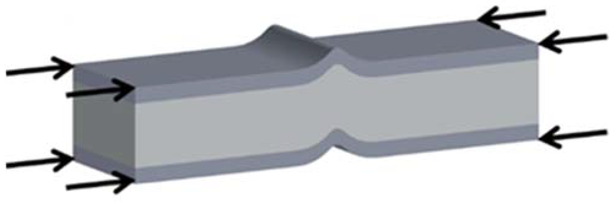
2. Compressive Test of Honeycomb Sandwich Panel

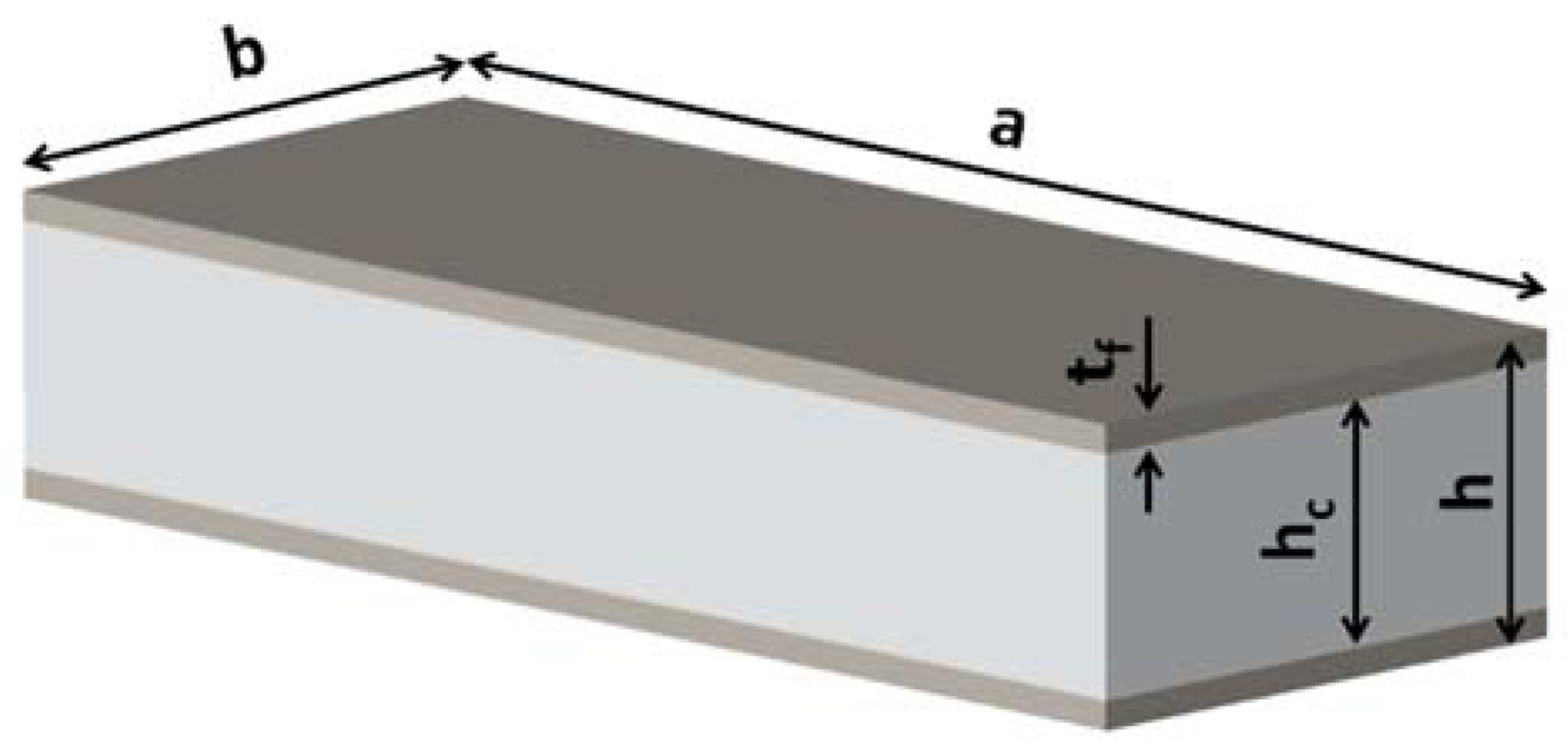
2.1. Research Object

The basic structural behaviour of sandwich panels is assumed to be as I-beams, where the facings sustain mainly bending and in-plane loads, with one skin or flange in compression and the other in tension. In contrast, the core acts as the web of an I-beam, carrying the shear load and improving the bending stiffness by separating the skins. Differently from an I-beam, it allows uniform support to the skins, distributing the loads and defining a uniformly stiffened panel. The core-to-skin adhesive rigidly joins the constituent parts, allowing them to act as one integral stiffened panel with high torsional and bending stiffness.
The honeycomb sandwich panel subjected to compressive loading may result in buckling failure, as seen in Figure 1, where a generic buckling failure mode for sandwich structures is depicted.
The current study analyses the honeycomb sandwich panel subjected to compressive loading. The aim is to investigate the governing factors and the possible implementation of existing models of buckling progressive failure [33], which may support the design of honeycomb sandwich panels for marine structural applications.

2.2. Research Methodology

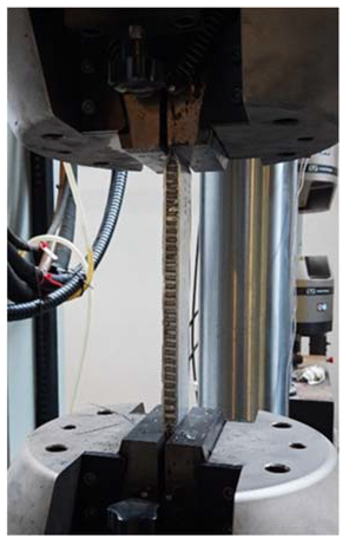
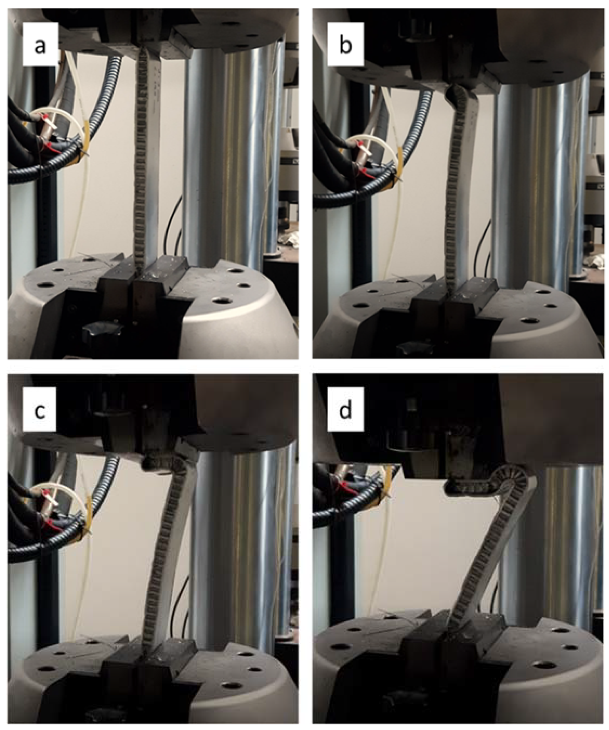
2.2.1. Experimental Analysis

Experimental analyses were performed using AHS panels to investigate compressive strength and verify and adjust the analytical approach in predicting the AHS panels’ stress–strain relationship and ultimate strength. AHS specimens used in the experimental investigation were obtained from commercial panels, where core–skins bonding was obtained with an industrial process using an epoxy resin. The main features of the base materials constituting the sandwich structure are summarised in Table 1, whereas Table 2 describes the characteristics of the tested AHS specimens.
The geometrical descriptors of the honeycomb panel are shown in Figure 2, where a is referred to as panel length, b as panel width, tf is the thickness of skins, hc is the core’s thickness, and h is the overall sandwich thickness.
Experimental tests were performed with a servo-hydraulic load machine (INSTRON 8854, Instron Inc., Norwood, MA, USA) using hydraulic grips, which enabled the specimens to be firmly held, as shown in Figure 3. The constraint applied to the specimens’ extremities was intended to model fully fixed boundary conditions.
Tests were performed under load control conditions at a load rate of 0.1 kN/s. To investigate the effect of the span, the tests were performed considering 130, 150, 170, 190, 210 and 220 mm spans. Two tests (defined as T1 and T2) were performed for each span to guarantee the repeatability of results. The pressure applied by the grips, which influences the boundary conditions, was set to 20 MPa.

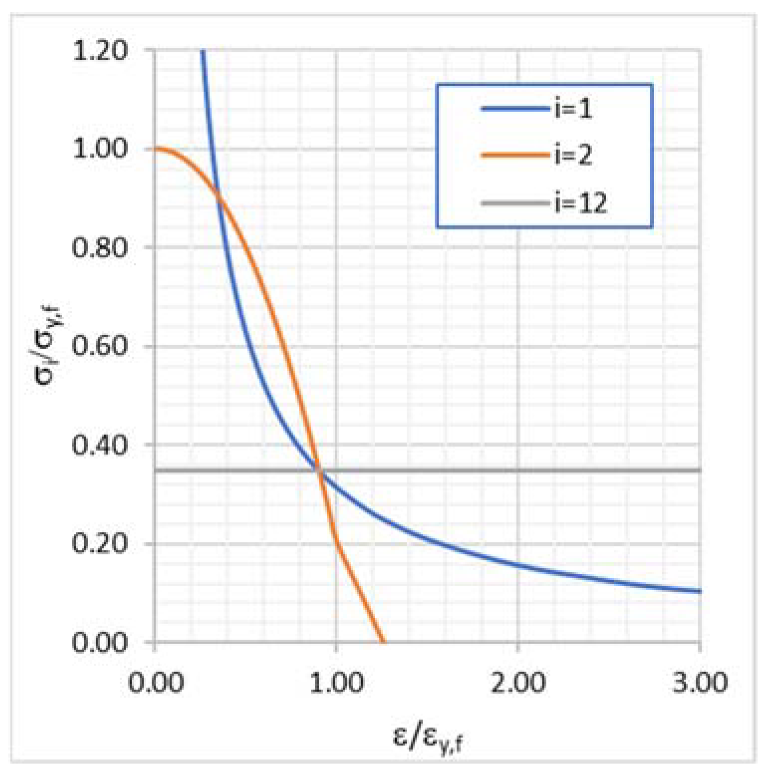
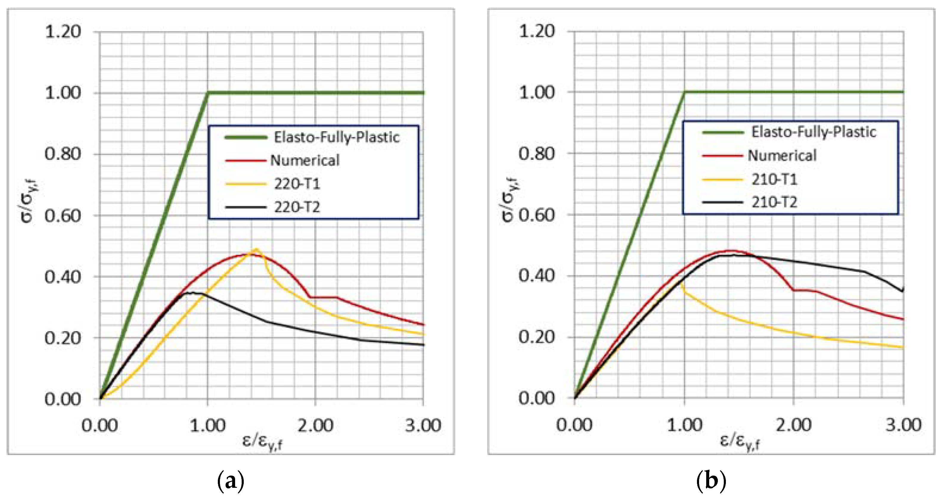
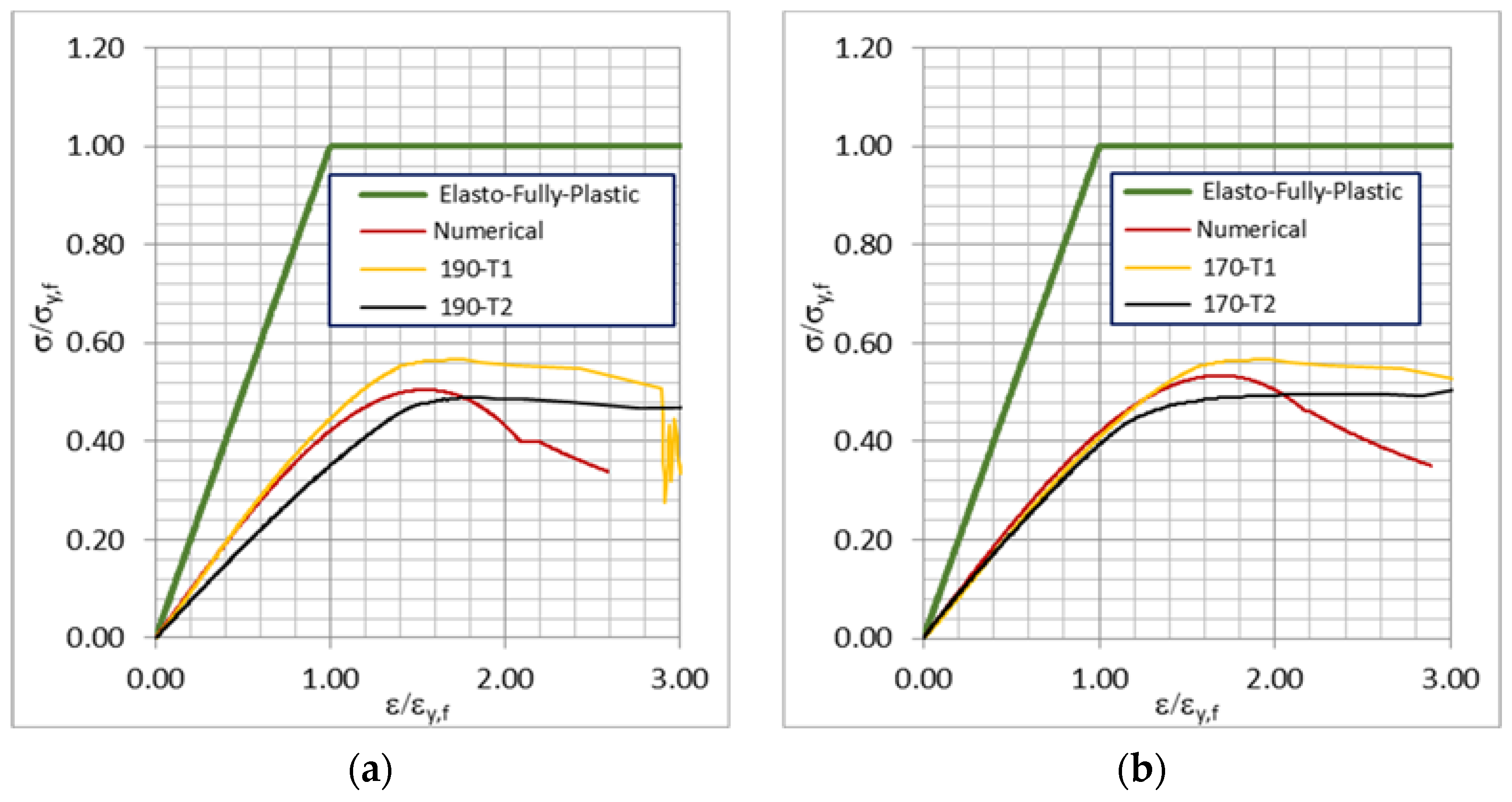
2.2.2. Prediction Model

The Smith [34] incremental–iterative approach was adapted to develop an analytical approach to estimate the stress–strain relationship and ultimate strength of the honeycomb panel, accounting for the critical stress based on the Johnson–Ostenfeld formulation [35] and the inelastic effects of the column’s buckling of the honeycomb panel, as defined in [33]. The descriptors of the employed formulations were calibrated to the experimental results in developing the load-shortening relationship throughout Equations (1)–(10).
The relationship describing the stress–strain relationship σ ε or the elastic–plastic collapse of the honeycomb panel, valid for both positive (shortening) and negative (lengthening) strains, is defined as the column buckling failure mode below:
σ = k σ Φ σ y , f
where k σ is a factor accounting for the debonding of the honeycomb panel cells, Φ is an edge function and σ y , f is the yield stress of the core material. The edge function is defined as follows:
Φ = { 1   for   ε < 1 ε   for 1 < ε < 1 1   for   ε > 1
Moreover, the debonding factor for the tested specimens is defined as:
k σ = 0.0783 a b + 0.7481
The relative strain is defined as:
ε = k ε   ε E / ε y , f
where ε y , f is the strain corresponding to the yield stress, ε E is the strain corresponding to the incremental load and k ε = 2.2 is a factor depending on the experimental conditions.
The load-end relationship σ C R 1 ε is defined as:
σ C R 1 = Φ σ C 1 ( A s + 10 2 b E t f A s + 10 2 b t f )
where σ C R 1 is the critical stress, A s is the net sectional area of the honeycomb panel without the skin plate, b is the skin plate breadth and t f is the thickness of the skin plate.
The loss of the efficiency of the skin plate due to compressive loading is accounted for by the term ( A s + b E t f ) / ( A s + b t f ) , where, in the case of a honeycomb panel A s = 0 , the effective width ( b E ) of the skin plate subjected to compressive load is defined based on the Frankland [36] calculation as follows:
b E = { b                                           for   β f < 1.25 ( a 1 β f a 2 β f ) b   for   β f 1.25
where a 1 and a 2 are constant as a function of the boundary conditions, where a 1 = 2.0 and a 2 = 1.0 for a simply supported panel and a 1 = 2.25 and a 2 = 1.25 for a clamped panel, as proposed in [37]. The skin plate’s slenderness is defined as:
β f = b t ε σ y , f E f
The critical stress σ C 1 , based on the Johnson–Ostenfeld formulation [35] and accounting for the inelastic effects on the column’s buckling, is defined as:
σ C 1 = { max [ σ 1 ,   σ 2     ]                           for   σ E 1 σ y , f 2 ε σ 2                                                                 for   σ E 1 > σ y , f 2 ε
where:
σ 1 = σ E 1 ε
σ 2 = σ y , f ( 1 Φ σ y , f ε 4 σ E 1 )
The crossing point of the stresses σ 1   and   σ 2 is defined as σ 12 , which is different from σ E 1 and an illustrative example of the application of Equation (8) can be seen in Figure 4, which shows the trend of descriptors of Equation (8). Here, i refers to the subscript of the stresses at the numerator of the term reported on the ordinates: σ 1   for   i = 1 ,   σ 2   for   i = 2 ,   σ 12   for   i = 12   .
The buckling stress of the honeycomb panel, σ E 1 , is defined as follows, according to [33]:
σ E 1 = π 2 D A E ( a 2 + π 2 D G w h b )
where G w is the shear modulus (considering the core shear to be in the weaker transverse direction) a is the span of the panel, h is the distance between facing skin centres and D is the bending stiffness defined as:
D = E f t f h 2 b E 2
where h = t f + h c . This prediction model is adapted for a honeycomb panel, represented by a column with a web plate thickness of 0 mm.

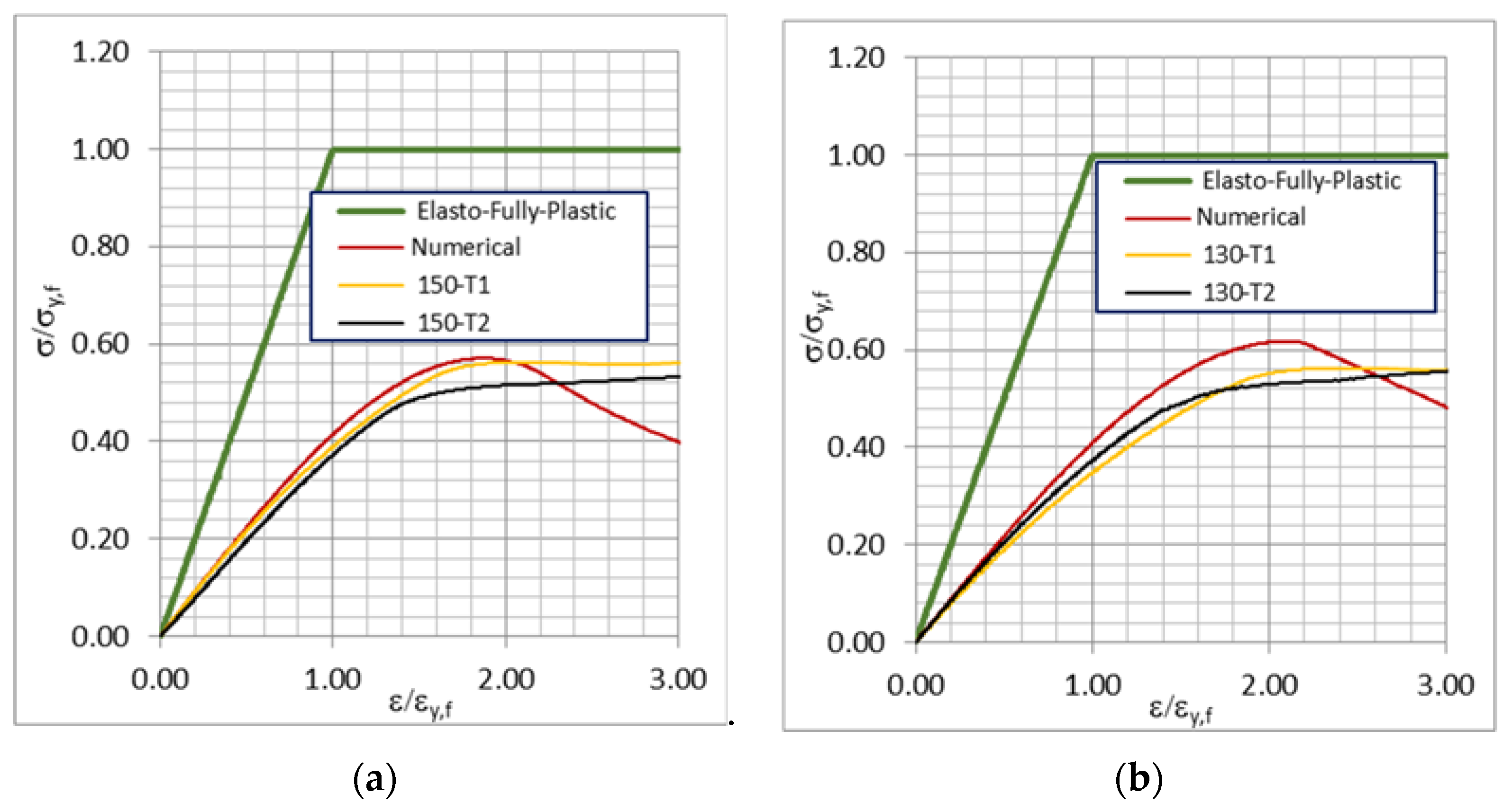
3. Results and Discussion

Load sequences during the experimental test are shown in Figure 5. First, a linear phase was observed, followed by buckling and post-buckling behaviour reaching the panel’s ultimate strength, and, finally, sudden collapse ends the test. During the linear phase of the loading event, no evidence of deformations or distortions were detectable, as visible in Figure 5a. The subsequent phases involving buckling failure were sudden and fast. The specimens’ collapse began with forming a plastic hinge near one of the extremities, as shown in Figure 5b. The side in which the plastic hinge forms was found to be random. The hinge formation, which resulted in a significant distortion of the skins and core, was followed by core/skin debonding on the panel side subjected to compressive loading. Core/skin debonding further propagated along the specimen (Figure 5c), producing a four-shaped deformed configuration (Figure 5d). The failure mode observed for all specimens was the same, and, as displayed in (Figure 5d), the post-collapse configuration did not present cracks in the skins, whereas the cores were torn apart.
The ultimate compressive strength and load-shortening relationships of the tested six sets of two specimens, T1 and T2, with spans from 130 to 220 mm, are analysed here.
All stress–strain relationships, as shown in Figure 6, Figure 7 and Figure 8, had a similar initial linear trend, which is a feature of the tested AHS; thus, this confirms the consistency of the experimental investigation. The sudden load fall observed in all curves represents the panel’s collapse after the load exceeded its ultimate strength. The irregular trend registered for some tests after load drop is symptomatic of the failure events occurring after the elastic–plastic collapse of the honeycomb panel, which involves core/skin debonding and core cracking and tearing. According to the experimental results, decreasing the specimen’s span increased its ultimate strength, according to what is expected from the classic buckling theory of columns. The relationship between the ultimate strength and ratio between the span and breadth of the specimens shows an inverse proportionality, as presented in Figure 9 and Figure 10a, where the experimental results, showing some scatter, for both sets of tests are reported.
The experimental and predicted stress–strain relationships are shown in Figure 6 for spans equal to 210 and 200 mm, Figure 7 for spans equal to 190 and 170 mm and Figure 8 for spans equal to 150 and 130 mm. The supports used in the experimental test are assumed to be clamped supports. As can be noticed from Figure 6, Figure 7 and Figure 8, there is good matching between the predicted and experimental results in the pre-collapse period, especially in the pre- and post-buckling period.
The experimental stress–strain relationships show initial linear growth and a good follow-up to the ultimate strength and subsequent drop in structural capacity. The ultimate strength is inversely proportional to the ratio a/b with an almost linear relationship, as shown in Figure 9 and Figure 10a. A correlation coefficient was estimated (about 0.82) to verify the scatter between experimental and predicted results, as seen in Figure 10b.

4. Conclusions

The current work aimed to pave the way towards more comprehensive integration of aluminium honeycomb sandwich structures in shipbuilding. The uniaxial axial compressive load condition was considered one of the most critical for ship structures. Hence, experimental investigations were performed to analyse the structural response under such conditions. The experimental results were also crucial to support the development of a numerical approach to predict the stress–strain relationship of AHS subjected to uniaxial compressive load which is essential information for structural ship design. The experimental results performed on AHS panels of different spans allowed the identification of the collapse mode as a function of the span, with the maximum load-carrying capacity varying from about 8 kN for the longer span to 12 kN for the shorter one. The trend of the load-shortening relationships confirms that ultimate strength is inversely proportional to the span. The observed patterns of the experimentally tested honeycomb panels subjected to a compressive load were used to develop a numerical model to predict the stress–strain behaviour and identify the ultimate strength. A validation study employing a correlation approach showed that the predicted numerical model can provide good estimations of the stress–strain relationships for honeycomb panels, with a correlation of 0.82 for the experiments performed. The application of the numerical prediction model can be extended to honeycomb stiffened panels and box girders. The numerical model developed in this study has limitations related to the analysis of honeycomb panels of small scales as well as to boundary conditions and cell size. This limitation may be overcome by testing more specimens of different sizes, configurations and boundary conditions as well as by adjusting the currently developed numerical model. This will lead to a new numerical approach that can be used for more complex marine structures, enhancing their impact-absorption capabilities and high stiffness-to-weight ratios.

Author Contributions

Conceptualisation, P.C., G.P., V.C. and Y.G.; methodology, P.C., G.P. and Y.G.; formal analysis, P.C., G.P. and Y.G.; investigation, P.C., G.P. and Y.G.; resources, V.C.; data curation, P.C. and Y.G.; writing—original draft preparation, P.C., G.P. and Y.G.; writing—review and editing, P.C., G.P., V.C. and Y.G.; supervision, V.C. and Y.G. All authors have read and agreed to the published version of the manuscript.

Funding

This research received no external funding.

Institutional Review Board Statement

Not applicable.

Informed Consent Statement

Not applicable.

Data Availability Statement

Data are contained within the article.

Acknowledgments

The fourth author has been supported by the Strategic Research Plan of the Centre for Marine Technology and Ocean Engineering, financed by the Portuguese Foundation for Science and Technology (Fundação para a Ciência e Tecnologia-FCT) under contract UIDB/UIDP/00134/2020.

Conflicts of Interest

The authors declare no conflict of interest.

References

  1. Paik, J.K.; Lee, D.H.; Noh, S.H.; Park, D.K.; Ringsberg, J.W. Full-Scale Collapse Testing of a Steel Stiffened Plate Structure under Cyclic Axial-Compressive Loading. Structures 2020, 26, 996–1009. [Google Scholar] [CrossRef]
  2. Doukas, H.; Spiliotis, E.; Jafari, M.A.; Giarola, S.; Nikas, A. Low-Cost Emissions Cuts in Container Shipping: Thinking inside the Box. Transp. Res. Part D 2021, 94, 102815. [Google Scholar] [CrossRef]
  3. Palomba, G.; Marchese, S.S.; Crupi, V.; Garbatov, Y. Cost, Energy Efficiency and Carbon Footprint Analysis of Hybrid Light-weight Bulk Carrier. J. Mar. Sci. Eng. 2022, 10, 957. [Google Scholar] [CrossRef]
  4. Palomba, G.; Epasto, G.; Sutherland, L.; Crupi, V. Aluminium Honeycomb Sandwich as a Design Alternative for Light-weight Marine Structures. Ships Offshore Struct. 2021, 17, 2355–2366. [Google Scholar] [CrossRef]
  5. Kortenoeven, J.; Boon, B.; de Bruijn, A. Application of Sandwich Panels in Design and Building of Dredging Ships. J. Ship Prod. 2008, 3, 125–134. [Google Scholar] [CrossRef]
  6. Nguyen, T.T.T.; Le, T.A.; Tran, Q.H. Composite Sandwich Structures in the Marine Applications. In Sandwich Composites; CRC Press: Boca Raton, FL, USA, 2022; pp. 277–291. ISBN 9781003143031. [Google Scholar]
  7. Palomba, G.; Corigliano, P.; Crupi, V.; Epasto, G.; Guglielmino, E. Static and Fatigue Full-Scale Tests on a Lightweight Ship Balcony Overhang with Al/Fe Structural Transition Joints. J. Mar. Sci. Eng. 2022, 10, 1382. [Google Scholar] [CrossRef]
  8. Li, Y.; Wu, X.; Xiao, W.; Wang, S.; Zhu, L. Experimental Study on the Dynamic Behaviour of Aluminium Honeycomb Sandwich Panel Subjected to Ice Wedge Impact. Compos. Struct. 2022, 282, 115092. [Google Scholar] [CrossRef]
  9. Wu, X.; Li, Y.; Cai, W.; Guo, K.; Zhu, L. Dynamic Responses and Energy Absorption of Sandwich Panel with Aluminium Honeycomb Core under Ice Wedge Impact. Int. J. Impact Eng. 2022, 162, 104137. [Google Scholar] [CrossRef]
  10. IMO. Fourth IMO GHG Study 2020; IMO: Singapore, 2020. [Google Scholar]
  11. Grimes, S.; Donaldson, J.; Gomez, G.C. Report on the Environmental Benefits of Recycling; Bureau of International Recycling: Brussels, Belgium, 2008. [Google Scholar]
  12. Schlesinger, M.E. Aluminum Recycling, 2nd ed.; CRC Press Taylor & Francis Group: Boca Raton, FL, USA, 2014; ISBN 9781466570252. [Google Scholar]
  13. Garbatov, Y.; Saad-Eldeen, S.; Guedes Soares, C. Hull Girder Ultimate Strength Assessment Based on Experimental Results and the Dimensional Theory. Eng. Struct. 2015, 100, 742–750. [Google Scholar] [CrossRef]
  14. Woloszyk, K.; Garbatov, Y.; Kowalski, J.; Samson, L. Experimental and Numerical Investigations of Ultimate Strength of Imperfect Stiffened Plates of Different Slenderness. Pol. Marit. Res. 2020, 4, 120–129. [Google Scholar] [CrossRef]
  15. Corigliano, P. On the Compression Instability during Static and Low-Cycle Fatigue Loadings of AA 5083 Welded Joints: Full-Field and Numerical Analyses. J. Mar. Sci. Eng. 2022, 10, 212. [Google Scholar] [CrossRef]
  16. SANDCORe Co-Ordination Action. Best Practice Guide for Sandwich Structures in Marine Applications; NewRail, University of Newcastle: Newcastle upon Tyne, UK, 2013. [Google Scholar]
  17. Andric, J.; Prebeg, P.; Palaversa, M.; Zanic, V. Influence of Different Topological Variants on Optimized Structural Scantlings of Passenger Ship. Mar. Struct. 2021, 78, 102981. [Google Scholar] [CrossRef]
  18. Wang, Z.; Yuan, T.; Kong, X.; Wu, W. A Universal Similarity Method and Design Procedure for Buckling Assessment of Stiffened Plates under Compression Load on Real Ships. Thin-Walled Struct. 2022, 181, 110025. [Google Scholar] [CrossRef]
  19. IMO. RESOLUTION MSC.454(100)—Revised Guidelines for Verification of Conformity with Goal-Based Ship Construction Standards for Bulk Carriers and Oil Tankers; IMO: London, UK, 2018. [Google Scholar]
  20. Lloyd’s Register. Rules and Regulations for the Classification of Ships; Lloyd’s Register: London, UK, 2022. [Google Scholar]
  21. Liu, B.; Yao, X.; Lin, Y.; Wu, W.; Guedes Soares, C. Experimental and Numerical Analysis of Ultimate Compressive Strength of Long-Span Stiffened Panels. Ocean Eng. 2021, 237, 109633. [Google Scholar] [CrossRef]
  22. Liu, B.; Chen, C.; Garbatov, Y. Material Failure Criterion in the Finite Element Analysis of Aluminium Alloy Plates under Low-Velocity Impact. Ocean Eng. 2022, 266, 113260. [Google Scholar] [CrossRef]
  23. Liu, B.; Doan, V.T.; Garbatov, Y.; Wu, W.; Soares, C.G. Study on Ultimate Compressive Strength of Aluminium-Alloy Plates and Stiffened Panels. J. Mar. Sci. Appl. 2020, 19, 534–552. [Google Scholar] [CrossRef]
  24. Wysmulski, P. The Effect of Load Eccentricity on the Compressed CFRP Z-Shaped Columns in the Weak Post-Critical State. Compos. Struct. 2022, 301, 116184. [Google Scholar] [CrossRef]
  25. Kubiak, T.; Kolakowski, Z.; Swiniarski, J.; Urbaniak, M.; Gliszczynski, A. Local Buckling and Post-Buckling of Composite Channel-Section Beams—Numerical and Experimental Investigations. Compos. B Eng. 2016, 91, 176–188. [Google Scholar] [CrossRef]
  26. Wysmulski, P.; Teter, A.; Debski, H. Effect of Load Eccentricity on the Buckling of Thin-Walled Laminated C-Columns. In AIP Conference Proceedings; American Institute of Physics Inc.: Woodbury, Long Island, NY, USA, 5 January 2018; Volume 1922. [Google Scholar]
  27. Wang, J.; Yi, B.; Zhou, H. Framework of Computational Approach Based on Inherent Deformation for Welding Buckling Investigation during Fabrication of Light-weight Ship Panel. Ocean Eng. 2018, 157, 202–210. [Google Scholar] [CrossRef]
  28. Eyvazian, A.; Taghizadeh, S.A.; Hamouda, A.M.; Tarlochan, F.; Moeinifard, M.; Gobbi, M. Buckling and Crushing Behavior of Foam-Core Hybrid Composite Sandwich Columns under Quasi-Static Edgewise Compression. J. Sandw. Struct. Mater. 2021, 23, 2643–2670. [Google Scholar] [CrossRef]
  29. Wei, X.; Wu, Q.; Gao, Y.; Yang, Q.; Xiong, J. Composite Honeycomb Sandwich Columns under In-Plane Compression: Optimal Geometrical Design and Three-Dimensional Failure Mechanism Maps. Eur. J. Mech. A/Solids 2022, 91, 104415. [Google Scholar] [CrossRef]
  30. Kardomateas, G.A.; Simitses, G.J.; Shen, L.; Li, R. Buckling of Sandwich Wide Columns. Int. J. Non-Linear Mech. 2002, 37, 1239–1247. [Google Scholar] [CrossRef]
  31. Léotoing, L.; Drapier, S.; Vautrin, A. First Applications of a Novel Unified Model for Global and Local Buckling of Sandwich Columns. Eur. J. Mech. A/Solids 2002, 21, 683–701. [Google Scholar] [CrossRef]
  32. Salazar-Domínguez, C.M.; Hernández-Hernández, J.; Rosas-Huerta, E.D.; Iturbe-Rosas, G.E.; Herrera-May, A.L. Structural Analysis of a Barge Midship Section Considering the Still Water and Wave Load Effects. J. Mar. Sci. Eng. 2021, 9, 99. [Google Scholar] [CrossRef]
  33. HexCel HexWeb Honeycomb Sandwich Design Technology. HexWeb Honeycomb sandwich design technology 2000, 1–28.
  34. Smith, C.S. Influence of Local Compressive Failure on Ultimate Longitudinal Strength of a Ship’s Hull. In Proceedings of the International Symposium on Practical Design in Shipbuilding, Tokyo, Japan, 17–21 October 1977; pp. 73–79. [Google Scholar]
  35. Timoshenko, S.P.; Gere, J.M. Theory of Elastic Stability; McGraw-Hill: New York, NY, USA, 1985; ISBN 0-07-Y85821-7. [Google Scholar]
  36. Frankland, J.M. The Strength of Ship Plating under Edge Compression. US EMB Rep. 1940, 469, 13–14. [Google Scholar]
  37. Faulkner, D. A Review of Effective Plating for Use in the Analysis of Stiffened Plating in Bending and Compression. J. Ship Res. 1975, 19, 1–17. [Google Scholar] [CrossRef]
Figure 1. Honeycomb sandwich panel buckling failure mode, as reported in [33].
Jmse 11 00365 g001
Figure 2. Honeycomb panel geometrical descriptors.
Jmse 11 00365 g002
Figure 3. Experimental setup.
Jmse 11 00365 g003
Figure 4. Descriptors of Equation (8).
Jmse 11 00365 g004
Figure 5. Load sequence during experimental tests: (a) test initiation; (b) plastic hinge formation; (c) core/skin debonding propagation; (d) post-collapse configuration.
Jmse 11 00365 g005
Figure 6. Stress–strain relationships of elastic–fully plastic numerical and experimental results of specimens T1 and T2 for a span of 220 mm (a) and 210 mm (b).
Jmse 11 00365 g006
Figure 7. Stress–strain relationships of elastic-fully plastic numerical and experimental results of specimens T1 and T2 for a span of 190 mm (a) and 170 mm (b).
Jmse 11 00365 g007
Figure 8. Stress–strain relationships of elastic–fully plastic numerical and experimental results of specimens T1 and T2 for a span of 150 mm (a) and 130 mm (b).
Jmse 11 00365 g008
Figure 9. Ultimate strength as a function of the length-to-breadth ratio.
Jmse 11 00365 g009
Figure 10. Normalised ultimate strength as a function of a/b (a) and correlation between experimental and predicted ultimate normalised strength (b).
Jmse 11 00365 g010
Table 1. Features of materials composing tested AHS.
Skin materialAA5754
Core materialAA5052
Skin Young’s modulus Ef [GPa]68
Skin yield stress σy,f [MPa]155
Core shear modulus Gw [MPa] 1372
Core density, ρ [kg/m3] 1130
1 Taken from [33].
Table 2. Features of tested AHS specimens.
Cell diameter [mm]3
Cell wall thickness [μm]70
Specimen width b [mm]45
Skin thickness [mm]1
Core thickness [mm]9
Overall thickness [mm]11
Disclaimer/Publisher’s Note: The statements, opinions and data contained in all publications are solely those of the individual author(s) and contributor(s) and not of MDPI and/or the editor(s). MDPI and/or the editor(s) disclaim responsibility for any injury to people or property resulting from any ideas, methods, instructions or products referred to in the content.

