Abstract
Based on the wave reflection principle, a floating flapping-panel wave energy converter was developed. The feasibility study and optimization study of the new WEC was carried out by laboratory research and computational fluid dynamics techniques. A numerical model was developed for an in-depth study to establish the relationship between slope tilt angle and power. The results for different wave periods show that the power take-off damping coefficient has a significant effect on the power. Meanwhile, the effects of flap length and wave height on converter resonance and power are investigated. Finally, a preliminary laboratory physical model test of the device is conducted. The flapping-panel-slope structure is very feasible and effective with good hydrodynamic performance.
1. Introduction
At present, there are various design models for wave energy conversion devices [1], which can be basically classified into offshore, nearshore and onshore devices, according to the installation location [2]. Offshore devices face huge survival pressure and high submarine cable laying costs, making commercial application very difficult. Nearshore and onshore devices are relatively simple and convenient in terms of survival and maintenance and may be a good option.
A number of wave energy converter (WEC) models with very good performance have emerged for both nearshore and onshore devices. The Oyster device developed by Queen’s University in the UK, which has been updated for two generations, has performed well in all specifications and has successfully achieved long-term stable operation in real sea conditions [3]. Unlike the Oyster, the WaveRoller uses a fully submerged floating pendulum that can be formed into an array of power modules, with all floating pendulum motion occurring below the water surface, and full-size wave energy generator WaveRoller installed in Portugal [4]. Eco Wave Power, which fixes pendulum wave energy conversion devices on shore base or combined with breakwaters, has now deployed physical models in several locations around the world and has successfully captured wave energy for power generation [5]. The flexible combination of Wavestar and offshore wind energy capture devices enables multi-energy hybrid absorption and improves commercial competitiveness [6].
To test the feasibility of a WEC model, physical model tests can generally be taken to solve a series of problems by simulating the realization of the phenomena of the interaction between structures and waves in the laboratory. Bosma et al. obtained a series of hydrodynamic parameters by conducting wave pool experiments on FOSWEC for comparison with numerical simulations for validation [7]; Wei et al. successfully implemented the kinematic response of multi-pump multi-piston power take-off system in the laboratory using wave tank experiments [8]. Davey’s team conducted long-term Round Robin tests of a Hinged Raft Wave Energy Converter in several laboratories and found that wave tank depth had little effect on the results [9].Physical model experiments require the construction of an experimental platform, which is a very expensive and time-consuming process but is very meaningful for scientific research.
Another option is the computational fluid dynamics (CFD) technique and has been widely used as a cost-effective experimental tool in the optimal design studies of marine structures. A WEC-Sim code was developed at Sandia Labs, USA that can be used to calculate the motion response and power output of a WEC model in waves [10]; Poguluri et al. tested the WEC-rotor using CFD techniques that can be well-matched with physical experimental results [11]; Ransley et al. calculated the Wavestar through the open source program OPENFOAM software [12]; Tezdogan et al. conducted simulation experiments using Star-CCM+ on a full-size hull model in deep and shallow water and provided an in-depth analysis of the results in shallow water [13]. The development of the Smoothed Particle Hydrodynamics model for wave-structure interaction is more in line with engineering standards in terms of numerical calculations [14]. It is worth noting that different model scales in numerical simulations can cause different degrees of error in the experimental results [15].
Various experimental methods, which have played a great role and convenience in the calculation and testing of WEC, are becoming more and more mature. However, the commercialization and real use of WEC is still very slow; one of the biggest constraints is the hydrodynamic performance of WEC. Much of the current WEC optimization work is precisely around the hydrodynamic performance [16,17]; how to design a hydrodynamic performance of the WEC may be the key to solve the problem.
In conclusion, with the emphasis on renewable energy, the development of wave energy technology is also facing opportunities and challenges. Based on the novel wave energy conversion device, this paper will introduce the working principle of the novel WEC in Section 2, and the physical experimental method of the model and the experimental details of CFD technology will be developed in Section 3. Finally, the relevant experimental results will be obtained in Section 4, and relevant meaningful results will be derived around the experimental results, hoping that can drive the wave energy generation technology forward.
2. A Floating Flapping-Panel WEC
Wan et al. studied and designed a near-shore-based floating flapping-panel wave energy conversion device [18], as shown in Figure 1. In our previous work, our team focused on the overall system workflow of the novel wave energy conversion device and the significant improvement in wave energy capture efficiency by the slope structure [19]. In this paper, we focus on optimizing the hydrodynamic performance module and initially discuss the effect of slope angle on the capture efficiency of the device, as well as other factors, such as its own shape. This has a forward-looking effect on the local and overall optimization of the floating flapping-panel wave energy conversion device.

Figure 1.
Schematic diagram of floating flapping-panel WEC.
By arranging a freely adjustable slope structure under the floating flapping-panel, the wave energy from the lower layer of the free liquid surface is enhanced by reflecting it near the free liquid surface, which boosts the energy of the wave field near the floating flapping-panel; therefore, the overall wave energy absorption efficiency can be enhanced. The waves impact the floating flapping-panel, drive the hydraulic device to do work, output electrical energy and return to the original position by their own gravity, cycling the above process, continuously carrying out power output and merging electrical energy into the grid or storing it in the battery.
The first described parameter was the floating swing force analysis under the wave force on the y-axis rotation. According to the momentum moment theorem, we have the dynamic equation:
where is the moment of inertia of floating flapping-panel around the shaft and represents the angular acceleration of the flapping-panel. indicates the fluid moment expressed as:
where is the floating force area; is the distance from the cell area of the flapping-panel to the rotation; is the tangential force of the buoyancy flapping-panel; is the normal force of the flapping-panel; and is the moment of gravity formulated as:
where the variables are: the initial state of gravity axis connection and horizontal angle; the rotation angle of the moment;mass of a buoyancy flapping-panel; gravity acceleration; and the distance from the center of gravity of the floating flapping-panel to the origin of coordinate. The power take-off (PTO) system torque moment is . The linear moment used here is , where is the coefficient of linear resistance moment, the flapping-panel angle acceleration and “” means that the floating flapping-panel was performed outside. The nonlinear moment is a constant torque load, and the PTO system is instantaneous power: .
The wave energy conversion device basically consists of a three-stage energy conversion process that converts wave energy into mechanical energy. The efficiency of a primary energy conversion depends on the hydrodynamic performance of the device [20]. Typically, the capture width ratio “” is used to evaluate the hydrodynamic performance of the device. This capture width ratio is equal to the wave energy input by the wave energy device and the wave energy input within the device width. The buoyancy flapping-panel device can be calculated using (4)
where is the width of flapping-panel = 0.4 (two-dimensional case); denotes conversion power; and represents wave power.
After the wave energy device is captured, the first-order energy conversion is achieved by overcoming the PTO damping. The conversion power is based on using linear PTO damping [21] and the average power per unit W. The resistance moment is proportional to the speed of the flapping-panel [22].
Furthermore, the conversion power of the device can be calculated by (6)
By substituting (6), the expression of width capture ratio can be obtained.
3. Model Test
This numerical simulation test uses Star-CCM+ software to establish a three-dimensional numerical wave flume, assuming that the slope structure is fixed and the floating pendulum does pitch motion near the still water surface and does not consider the motion of the water platform and the effect on the WEC, as shown in Figure 1. And three areas are set up, which are wave generation zone, working zone and wave absorbing zone.
Wan et al. built the computer-aided design software and imported it into Star-CCM+ [18]. The trimmed cell mesh and prismatic layer mesh were often used to generate the mesh in the Star-CCM+. The trimmed cell mesh was used to produce high-quality grids for complex grid generation problems. It can produce non-structural hexahedral meshes on complex geometric surfaces. The prismatic layer mesh can be used to control the boundary layer and make the Y+ out of the development zone.
In order to capture the free surface and the device, meshes should be refined according to The International Towing Tank Conference (ITTC), and there were at least 100 grids in the wavelength range on the free surface. In addition, a minimum of 20 grids was used in the wave height direction of the free surface. The mesh is shown in Figure 2A. In order to ensure more accurate calculations and not to waste computational resources, the meshes of the background calculation area, the motion overlap area and the meshes around the free surface regular waves are refined, as shown in Figure 2B.

Figure 2.
Mesh of the model (A), Mesh generation details of the WEC model (B).
It may be noted that the RANS solver [13], a segregated numerical flow model where the flow equations were solved in an uncoupled way, was adopted in all the simulations in this paper. Convection terms in the RANS formulae were discretized by employing second-order upwind schemes. The general solution was obtained based on a SIMPLE-type algorithm.
In order to predict realistic flapping-panel behavior, a Dynamic Fluid Body Interaction (DFBI) model was adopted. The DFBI model was integrated with the RANS solver to compute the exciting force and moments acting on the flapping-panel hull caused by waves and to solve the governing equations of rigid body motions to relocate the rigid body.
In order to reduce the computational complexity and requirements, only one-half of the floating flapping-panel device was calculated. The velocity inlet is in the negative × direction, where the incident regular wave was generated. The initial velocity at the inlet was set to the corresponding speed of the waves, as shown in Figure 1. Inside the tank, water and air are used as two-phase flow, so the pressure outlet is set at the top, which is consistent with the actual situation. The sliding wall was selected as the bottom boundary condition due to the large water depth. The symmetrical boundary in the positive y direction was used for the symmetry of the device, and the symmetrical boundary in the negative y direction was used to prevent the fluid from adhering to the wall.
4. Results & Discussion
4.1. Relationship between Slope Angle and Power
The bottom slope structure affects the reflection of waves from the underwater surface [23], and how to choose a reasonable slope angle (the angle between the slope structure and the static water surface, as shown in Figure 1) is important to improve the efficiency of the wave energy conversion device. In the experiment, the angle of the slope is adjusted several times for different angles , resulting in changes in the power and energy captured by the wave energy hydrodynamic device.
In this experiment, we take the following conditions as the basic initial conditions; the experimental process is always unchanged and all in the same sea state conditions. The flapping-panel length was 8 m, and damping coefficient was 3,500,000.
Figure 3 and Figure 4 show the power and captured energy at different flapping-panel-slope angles. It is observed that the optimum angle was 35 degrees. When the flapping-panel-slope angle increased above 35 degrees, the upward reflection of the slope on the fluid decreased so that the force of the fluid on the floating flapping-panel was reduced. When the slope angle was below 35 degrees, by decreasing the angle, there was a decrease in the incoming wave energy captured.

Figure 3.
Power curves with different slope angles.

Figure 4.
Captured wave energy with different slope angles.
Obviously, under the above conditions, the conclusions we obtained have some limitations, which are directly related to the sea conditions. For different wave heights and different wave periods, the optimal angle of the slope will change, and the next goal of the team will be to study the optimal angle of different slopes under multiple sea conditions to meet the needs of complex and variable sea conditions and to actively change the slope angle so that the floating flapping-panel is always in a large wave energy field, thus improving the first-level capture efficiency.
4.2. Relationship between PTO Damping Coefficients and Power
The PTO damping factor of the wave energy conversion device is a very important parameter in the process of absorbing wave energy, and many scholars have done research on this. There exists a proper PTO damping factor that can make the device resonate and significantly improve the effect of wave energy capture.
According to Zhao et al.’s study on bottom hinged pendulum wave energy device, the optimal PTO damping coefficient has the following relationship with radiation damping [24]:
In the above equation, is the restoring force coefficient; is the moment of inertia of the floating pendulum; is the additional moment of inertia; and is the radiation damping.
It is obtained from the above equation that the optimal PTO damping coefficient is equal to the radiation damping coefficient in order of magnitude, so in the selection of the test damping coefficient, then it is kept in the same order of magnitude as the radiation damping and increases in order from small.
The influence of different PTO damping coefficients on the floating flapping-panel efficiency is studied by performing numerical simulations of the floating flapping-panel at different damping coefficients . When the interaction between the wave and the floating flapping-panel was stable, the selected power cycles are as shown in Figure 5 with the wave periods T = 5 s, T = 6 s and T = 7 s as well as the wave height of 1 m. It can be seen from Figure 5 that at different damping coefficients, the effective power was the smallest when the wave period was 5 s and the effective power was similar for T = 6 s and T = 7 s. The work time was the shortest when T = 5 s while the longest when T = 7 s. As the damping coefficient increased, the effective power of different wave periods increased at first and then decreased.
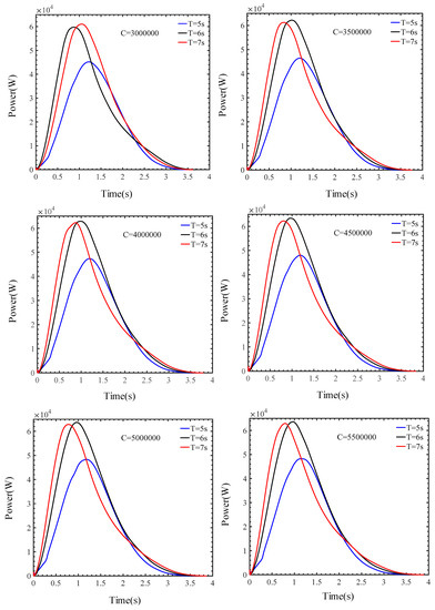

Figure 5.
Power curves at different linear moment coefficient.
Therefore, there were optimal damping coefficients for different wave periods. For wave periods T = 5 s, T = 6 s and T = 7 s the effective power reached the maximum when the damping coefficient was 5,000,000 , 450,000 and 5,500,000 , respectively, as shown in Figure 6. The maximum effective power values were observed to be 48.32 kW, 64.21 kW and 63.33 kW, respectively. This indicated that the floating flapping-panel efficiency depended on the PTO damping coefficient [25].

Figure 6.
Different wave period power curves.
It is found that, when the wave period is T = 5 s, T = 6 s and T = 7 s, the energy increased at first and then decreased as the PTO damping coefficient increased. The power reached the maximum at the damping coefficient of 5,000,000 , 4,500,000 and 5,500,000 . As shown in Table 1, longer wave periods led to lower wave energy conversion efficiency. It might be attributed to the effects of floating flapping-panel length L on the floating flapping-panel moving time and the wave energy conversion efficiency. Therefore, the value of L is changed to verify the above observation.

Table 1.
Wave energy conversion efficiency.
As shown in Table 2 and Figure 7, longer flapping-panel length became longer and improved the wave energy conversion efficiency under each wave period due to longer work time. However, as shown in Figure 8, the floating flapping-panel could not return to the origin to achieve resonance in the case when LP = 10 m and T = 5 s, which was not conducive to structural stability. The floating flapping-panel worked well when m and . When and , the floating flapping-panel returned to the origin and continued to move downward, which would result in a waste of wave energy. In summary, long flapping-panel caused a long time of wave action. However, since the floating flapping-panel contacted wave surface earlier when moving downward, it cannot return to the initial position. In the case of short flapping-panel length, the floating flapping-panel would return to the initial position as expected to achieve resonance.
Table 2.
Different flapping-panel length efficiency comparison.

Figure 7.
Power with different flapping-panel lengths.

Figure 8.
Floating swing angle over time.
4.3. Physical Model Preliminary Test
The floating flapping-panel wave energy converter was fixed in the wave water tank, as shown in Figure 9. The water tank walls functioned as the walls of the floating flapping-panel wave energy converter. The horizontal position of the flapping-panel was 30 m from the wave-making area, long enough for waves to develop fully.

Figure 9.
Physical model preliminary test.
The flapping-panel movement was recorded by a camera and was post-processed to get the height displacement of the flapping-panel flapping end. During the measurement, the guide rope was loose when the flapping-panel flapped upward under the wave action; it became tight when the flapping-panel moved to the maximum height. It was smoothly controlled to slowly lay down the flapping-panel to avoid possible reflected waves which affect the incident wave.
To further study the feasibility of the above fundamental design, the whole system model was developed as presented in Figure 9, where the supporting frame, slope, flapping-panel, hydraulic rod pump, hydraulic motor and electric generator were included. The flapping-panel was manufactured by lightweight material, and the flapping-panel frame was hinged on the supporting frame. This system was installed in the wave tank according to the schematic design in Figure 1. During the experiment, mechanical energy held by the flapping-panel was converted to high-pressure hydraulic energy [26]. The hydraulic pump provided high-pressure hydraulic oil to drive the hydraulic motor, and the motor in turn powers the electric generator through speed accelerating the gearbox. After scale conversion, some base data and wave tank parameters are obtained, as shown in Table 3.
Table 3.
Water tank test parameter table.
In the laboratory of Zhoushan Campus of Zhejiang University, the hydrodynamic feasibility study experiment of the floating flapping-panel WEC was carried out.
The laboratory physical model experimental results showed that this system can provide enough power to light the connected LED when the wave height H was 0.06 m and wave periods T were 1.2 s, 1.4 s, 1.6 s, 1.9 s as well as 2.5 s with a corresponding output pressure of hydraulic pump of 1 MPa. This performance confirmed the feasibility of the fundamental study and structure design in this paper. The test rocker hydraulic pump outputs high-pressure hydraulic oil, which directly drives the hydraulic motor. After the gearbox was accelerated, the generator was energized and fixed to the tank, as shown in Figure 9, the light “ZJU” character consists of 30 0.5 W LED lights, and the maximum instantaneous power is 15 W.
5. Conclusions & Future work
In this paper, the floating flapping-panel wave energy conversion device was tested by numerical simulation studies; its hydrodynamic performance was quantitatively analyzed; and finally, a laboratory physical model hydrodynamic study was conducted to initially verify the feasibility of the device. The following conclusions were obtained:
- The simulation test study showed that the angle between the slope and the horizontal plane significantly influenced the efficiency of the wave energy converter. The optimal slope angle is 35 degrees, and the wave energy captured in the experimental sea conditions is the largest.
- Meanwhile, from the output characteristics under different PTO damping coefficients for the linear damping, an optimal coefficient was obtained to give maximum captured energy. The wave energy converter became more efficient as PTO damping coefficients fell.
- The length of the flapping-panel will affect the efficiency and resonance of the wave energy converter. With the increase of incident wave height, the wave energy converter can capture more energy.
- In the follow-up work, we will continue to carry out in-depth research around it, optimize the design and achieve high-efficiency capture of wave energy.
Author Contributions
T.S., methodology, data curation, software; Z.L., data curation, analysis, writing—original draft, writing—review and editing; H.Z., software, data curation, analysis, writing—original draft; C.L., writing—review and editing, supervision; Z.W., conceptualization, methodology, formal analysis. All authors have read and agreed to the published version of the manuscript.
Funding
The support by National Natural Science Foundation of China (NOs. 11572283, 11602179), the Education Department Foundation of Liaoning Province (NO. LJKZ0303), the National Key Research & Development Plan of China (NOs. 2017YFC1403306), the Public Science and Technology Research Funds Projects of Ocean (201205015), the Program for Zhejiang Leading Team of S & T Innovation (NO. 2010R50036) and HPC Center OF ZJU (ZHOUSHAN CAMPUS) are all gratefully acknowledged.
Institutional Review Board Statement
Not applicable.
Informed Consent Statement
Not applicable.
Data Availability Statement
Data available on request due to restrictions of privacy.
Conflicts of Interest
The authors declare no conflict of interest.
References
- Babarit, A.; Hals, J.; Muliawan, M.J.; Kurniawan, A.; Moan, T.; Krokstad, J. Numerical Benchmarking Study of a Selection of Wave Energy Converters. Renew. Energy 2012, 41, 44–63. [Google Scholar] [CrossRef]
- López, I.; Andreu, J.; Ceballos, S.; Martínez de Alegría, I.; Kortabarria, I. Review of Wave Energy Technologies and the Necessary Power-Equipment. Renew. Sustain. Energy Rev. 2013, 27, 413–434. [Google Scholar] [CrossRef]
- Whittaker, T.; Folley, M. Nearshore Oscillating Wave Surge Converters and the Development of Oyster. Philos. Trans. R. Soc. Math. Phys. Eng. Sci. 2012, 370, 345–364. [Google Scholar] [CrossRef] [PubMed]
- AW-Energy. Waveroller. 2022. Available online: https://aw-energy.com/waveroller/ (accessed on 9 October 2022).
- Tul Huda Ahmad, N.H.; Zamri Ibrahim, M.; Rahman, S.J.A.; Albani, A.; Mohad, S. The Development of Wave Energy Converter System Using Hydraulic Power Take Off at Terengganu Shoreline. In Proceedings of the 2018 International Conference and Utility Exhibition on Green Energy for Sustainable Development (ICUE), Phuket, Thailand, 24–26 October 2018; pp. 1–7. [Google Scholar]
- Ghafari, H.R.; Ghassemi, H.; Neisi, A. Power Matrix and Dynamic Response of the Hybrid Wavestar-DeepCwind Platform under Different Diameters and Regular Wave Conditions. Ocean Eng. 2022, 247, 110734. [Google Scholar] [CrossRef]
- Bosma, B.; Simmons, A.; Lomonaco, P.; Ruehl, K.; Gunawan, B. WEC-Sim Phase 1 Validation Testing: Experimental Setup and Initial Results. In Proceedings of the International Conference on Ocean, Offshore and Arctic Engineering, Busan, Republic of Korea, 19 June 2016; Volume 6, p. V006T09A025. [Google Scholar]
- Wei, Y.; Barradas-Berglind, J.J.; Van Rooij, M.; Prins, W.A.; Jayawardhana, B.; Vakis, A.I. Investigating the Adaptability of the Multi-Pump Multi-Piston Power Take-off System for a Novel Wave Energy Converter. Renew. Energy 2017, 111, 598–610. [Google Scholar] [CrossRef]
- Davey, T.; Sarmiento, J.; Ohana, J.; Thiebaut, F.; Haquin, S.; Weber, M.; Gueydon, S.; Judge, F.; Lyden, E.; O’Shea, M.; et al. Round Robin Testing: Exploring Experimental Uncertainties through a Multifacility Comparison of a Hinged Raft Wave Energy Converter. J. Mar. Sci. Eng. 2021, 9, 946. [Google Scholar] [CrossRef]
- Ruehl, K.; Forbush, D.D.; Yu, Y.-H.; Tom, N. Experimental and Numerical Comparisons of a Dual-Flap Floating Oscillating Surge Wave Energy Converter in Regular Waves. Ocean Eng. 2020, 196, 106575. [Google Scholar] [CrossRef]
- Poguluri, S.K.; Kim, D.; Bae, Y.H. Performance Assessment of Pitch-Type Wave Energy Converter in Irregular Wave Conditions on the Basis of Numerical Investigation. Ocean Syst. Eng. 2022, 12, 23–38. [Google Scholar]
- Ransley, E.J.; Greaves, D.M.; Raby, A.; Simmonds, D.; Jakobsen, M.M.; Kramer, M. RANS-VOF Modelling of the Wavestar Point Absorber. Renew. Energy 2017, 109, 49–65. [Google Scholar] [CrossRef]
- Tezdogan, T.; Incecik, A.; Turan, O. Full-Scale Unsteady RANS Simulations of Vertical Ship Motions in Shallow Water. Ocean Eng. 2016, 123, 131–145. [Google Scholar] [CrossRef]
- Zhang, D.H.; Shi, Y.X.; Huang, C.; Si, Y.L.; Huang, B.; Li, W. SPH Method with Applications of Oscillating Wave Surge Converter. Ocean Eng. 2018, 152, 273–285. [Google Scholar] [CrossRef]
- Pierart, F.G.; Fernandez, J.; Olivos, J.; Gabl, R.; Davey, T. Numerical Investigation of the Scaling Effects for a Point Absorber. Water 2022, 14, 2156. [Google Scholar] [CrossRef]
- Guo, B.; Ringwood, J.V. Geometric Optimisation of Wave Energy Conversion Devices: A Survey. Appl. Energy 2021, 297, 117100. [Google Scholar] [CrossRef]
- Zhang, H.; Zhou, B.; Vogel, C.; Willden, R.; Zang, J.; Geng, J. Hydrodynamic Performance of a Dual-Floater Hybrid System Combining a Floating Breakwater and an Oscillating-Buoy Type Wave Energy Converter. Appl. Energy 2020, 259, 114212. [Google Scholar] [CrossRef]
- Wan, Z.; Zheng, H.; Sun, K.; Zhang, D.; Yao, Z.; Song, T. Simulation of Wave Energy Converter with Designed Pendulor-Slope Combination. Energy Procedia 2019, 158, 733–737. [Google Scholar] [CrossRef]
- Wan, Z.; Li, Z.; Zhang, D.; Zheng, H. Design and Research of Slope-Pendulum Wave Energy Conversion Device. J. Mar. Sci. Eng. 2022, 10, 1572. [Google Scholar] [CrossRef]
- Elwood, D.; Yim, S.C.; Prudell, J.; Stillinger, C.; Von Jouanne, A.; Brekken, T.; Brown, A.; Paasch, R. Design, Construction, and Ocean Testing of a Taut-Moored Dual-Body Wave Energy Converter with a Linear Generator Power Take-Off. Renew. Energy 2010, 35, 348–354. [Google Scholar] [CrossRef]
- Johanning, L.; Smith, G.H.; Wolfram, J. Measurements of Static and Dynamic Mooring Line Damping and Their Importance for Floating WEC Devices. Ocean Eng. 2007, 34, 1918–1934. [Google Scholar] [CrossRef]
- Zhao, H.; Sun, Z.; Hao, C.; Shen, J. Numerical Modeling on Hydrodynamic Performance of a Bottom-Hinged Flap Wave Energy Converter. China Ocean Eng. 2013, 27, 73–86. [Google Scholar] [CrossRef]
- Midya, C.; Kanoria, M.; Mandal, B.N. Scattering of Water Waves by Inclined Thin Plate Submerged in Finite-Depth Water. Arch. Appl. Mech. 2001, 71, 827–840. [Google Scholar] [CrossRef]
- Zhao, H.; Sun, Z.; Shen, J.; Ning, D.-Z.; Xu, X. Time-Domain Model on Hydrodynamic Performance of a Bottom-Hinged Flap Wave Energy Converter. Chin. J. Hydrodyn. 2013, 28, 151–158. [Google Scholar]
- Falcão, A.F.D.O. Modelling and Control of Oscillating-Body Wave Energy Converters with Hydraulic Power Take-off and Gas Accumulator. Ocean Eng. 2007, 34, 2021–2032. [Google Scholar] [CrossRef]
- Kofoed, J.P.; Frigaard, P.; Friis-Madsen, E.; Sørensen, H.C. Prototype Testing of the Wave Energy Converter Wave Dragon. Renew. Energy 2006, 31, 181–189. [Google Scholar] [CrossRef]
Disclaimer/Publisher’s Note: The statements, opinions and data contained in all publications are solely those of the individual author(s) and contributor(s) and not of MDPI and/or the editor(s). MDPI and/or the editor(s) disclaim responsibility for any injury to people or property resulting from any ideas, methods, instructions or products referred to in the content. |
© 2023 by the authors. Licensee MDPI, Basel, Switzerland. This article is an open access article distributed under the terms and conditions of the Creative Commons Attribution (CC BY) license (https://creativecommons.org/licenses/by/4.0/).