Abstract
In instances where vessels encounter impacts or other factors leading to communication impairments, the status of electrical equipment becomes inaccessible through standard communication lines for the controllers. Consequently, the shipboard power system enters the partial observable state. Failure to timely ascertain and respond to the current state of the shipboard power system with appropriate restorative controls can result in irreversible damages to the electrical infrastructure and potentially precipitate a complete systemic failure. In this paper, an innovative fault-tolerant control and state estimation approach is proposed to address the partial observability problem of shipboard power systems, based on distributed control architecture and hybrid automata modeling, where controllers are unable to fully acquire equipment status due to device failures like sensor malfunctions. This approach infers the overall state of subsystems using data from intact equipment and discrete events from circuit breakers. Through fault-tolerant control techniques, it ensures that the subsystem state avoids invalid regions, effectively preventing the system from entering unhealthy operational states and significantly reducing the risk of performance degradation or systemic collapse due to faults. Simulation results confirm that this approach can quickly and accurately estimate the system’s current state under partial observation, enabling subsequent fault recovery strategies to accurately pinpoint fault locations and identify optimal recovery solutions.
1. Introduction
The comprehensive shipboard power system (SPS) has emerged as the primary focus for the future of maritime vessels. In comparison to traditional ships, an SPS significantly reduce lifecycle costs, enhance comfort, and provide crucial support for propulsion, detection, combat, communication, navigation, and daily life. Numerous electrical components on ships are powered through the electrical grid [1], contributing to increased complexity in the network topology [2] as the scale and complexity of SPSs continue to grow [3].
The interdependence of power supply networks, generator inertia, power generation capacity limitations, and stringent emission requirements, coupled with continuous loads such as electric propulsion systems and intermittent high-power loads like electromagnetic guns and radars [4], renders SPSs more fragile and susceptible to failures. Considering the extreme operating environments of ships, the probability of multiple and consecutive failures in an SPS is elevated.
The causes of SPS failures can be broadly categorized into two types: failures in electrical equipment [5], causing minimal damage with limited impact, usually resolved through protective control systems, and failures resulting from external factors such as collisions or enemy attacks. The latter type can lead to severe damage to both the ship and its power system. Additionally, during combat, the ship may encounter multiple concurrent failures after sustaining hits.
Due to the relatively small reserve capacity of an SPS, abnormal operation or failures causing single-point faults can significantly disrupt the system, potentially resulting in complete power loss across the entire ship. This, in turn, jeopardizes the safe and reliable operation of the ship and may lead to catastrophic events. Therefore, in the event of system failures and partial observability, prompt fault detection and localization are essential [6]. Subsequent measures must be taken to restore power to the faulty area rapidly, reduce the affected power outage area, and enhance ship safety [7].
Current research efforts by both domestic and international experts predominantly focus on improving algorithmic optimization capabilities to address stochastic failure issues [8]. An enhanced particle swarm optimization algorithm (ASODSTA), combining discrete state transition with binary particle swarm optimization, demonstrated improved computational speed and superior global convergence in scenarios involving ship circular grid lines and generator failures [9]. Intelligent retrieval of ship failure information was achieved through preprocessing of ship failure data and designing an intelligent retrieval algorithm [10]. A cloud computing-supported algorithm was presented for the complex querying of extensive ship failure data, focusing on query performance prediction [11]. A hybrid fault diagnosis method for SPS generator-end short-circuit faults was proposed, integrating multi-level wavelet decomposition networks, deep gated recurrent neural networks, and fully convolutional networks [12]. Vector quantization feature coding technology was employed for distributed storage structure analysis of extensive ship failure data, and segmented adaptive regression analysis was employed for spectral feature analysis [13].
Most studies consider the system in a fully observable state. However, traditional fault localization methods are ineffective when partial information about electrical equipment is missing. In partially observable scenarios, fault-tolerant control and state estimation are utilized to mitigate the effects of faults [14]. An active fault-tolerant control (AFTC) strategy for load frequency control (LFC) has been proposed, ensuring a smooth transition of LFC systems during physical/network faults, thereby enhancing grid reliability [15]. A fault-tolerant FSTP SSC strategy based on DFIM-SPS, namely PCSVM-DPC, has been introduced, offering easy implementation without significant computational burden [16]. Employing fault-tolerant BTBPC to traverse single-bridge faults allows DFIM-SPS to operate continuously at sea [17]. A fault-tolerant load frequency control (LFC) design for grid-connected wind power systems has been investigated. Compared to traditional LFC schemes, the fault-tolerant LFC scheme addresses known and unknown actuator faults caused by load disturbances and wind speed fluctuations [18]. A data-driven fault detection and fault-tolerant control scheme for large-scale systems has been researched. For paired subsystems, observer-based residual generators and observer-based state feedback controllers have been further developed in a distributed manner for fault detection and fault-tolerant control purposes [19]. However, fault-tolerant control in SPS is still rarely addressed.
Furthermore, fault state estimation under various fault conditions was addressed in several studies. A distributed control algorithm was designed to analyze scenarios involving four to six fault positions along with multiple concurrent failures [20]. The economic benefits of distributed SPS methods were quantified using a case study of a cruise ship with nine fire zones [21].
In this paper, the authors continue their research based on a previous hybrid model [22]. In combining with a distributed control framework, this paper proposed a state estimation approach under partial observability, where controllers deduce the current state of the system based on the status and events of observable devices. This approach, in conjunction with fault-tolerant control strategies, ensures that the system does not enter invalid states that could lead to failure.
Based on hybrid modeling, the novelty and intellectual merits of this paper can be summarized as the following:
- (1)
- This paper presents a state estimation approach capable of rapidly and accurately locating fault positions within a partially observable SPS, thereby determining the current state of the system.
- (2)
- The state estimation approach is proposed based on distributed fault-tolerant control, which fully leverages the zonal distribution structure of SPS and ensures that subsystems do not enter invalid states.
- (3)
- Simulation cases are conducted to show that a state estimation approach significantly reduces computational workload and time, surpassing traditional fault localization methods by achieving a computational time reduction of two orders of magnitude, thus enhancing the efficacy of fault recovery strategies and overall system management.
The remainder of this paper is organized as follows: Section 2 introduces the distributed fault-tolerant control of an SPS, proposing two fault-tolerant control methods. Section 3 explains the state estimation of an SPS under partial observability, deriving state range estimates under different fault conditions and recoverable conditions. Simulation processes and results are provided in Section 4, followed by the conclusions.
2. Distributed Fault-Tolerant Control of an SPS
In this section, a distributed fault-tolerant control strategy is proposed, building upon the hybrid modeling framework from previous work to prevent the system from entering invalid states that could lead to a potential collapse. Due to the characteristics of high integration, increased power equipment, and substantial control complexity in an SPS, traditional centralized control strategies are no longer suitable for current maritime developments. In leveraging the advantages of fast computational speed and the absence of single-point failure risks inherent in distributed control methods, this paper integrates the topological features of an SPS to construct a distributed fault-tolerant control that enhances system resilience. Based on the control tasks assigned to the system’s internal devices, both intra-region and inter-region control tasks are defined, decomposing fault recovery tasks into subsystem and global coordination layers to separately calculate different objectives.
2.1. Distributed Control System
The distributed control framework adopted in this paper comprises two hierarchical levels: the subsystem control layer and the global coordination layer, as illustrated in Figure 1. The SPS is divided into finite regions, with each region treated as a subsystem. Each subsystem has its local controller, executing tasks involving intra-region control, communication with adjacent regions, and communication with the coordinator. Additionally, each device within the system has its internal controller to reflect and control the device’s connectivity and accept commands from the local controller in the respective region. Finally, a communication network exists between the coordinator and distributed controllers to transmit necessary fault information, enabling inter-region control and completing the system’s global control tasks.
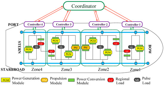
Figure 1.
Diagram of the distributed control topology for an SPS.
Under the distributed control framework, the control tasks of each distributed controller include intra-region fault protection, basic load management, and response to sudden disturbances within its designated region. This paper exclusively considers intra-region control tasks. Correspondingly, the coordinator can be employed to execute more complex inter-region control, although in this context, only its global coordination control tasks are considered. When fault recovery plans generated by distributed controllers are insufficient to resolve system faults, controllers request the coordinator to execute global control while concurrently awaiting the coordinator’s feedback. The coordinator receives proposed solutions from all relevant controllers, selects the optimal global coordination plan based on fault conditions, and communicates the plan to the respective controllers for the execution of fault-tolerant control.
2.2. SPS Distributed Control Model
This paper also employs the hybrid modeling method from the referenced literature [22], representing subsystem hybrid models as hybrid automata:
where is the state space, is finite, is the set of output variables, is the set of continuous control inputs, is the set of initial conditions, is the set of continuous state evolution laws describing the continuous state corresponding to each , is the set of algebraic equations for each , and is the set of discrete events, where is the set of controllable events, is the set of uncontrollable events, is the event generator function, is the discrete state transition relation, and is the reset relation; that is, the control behavior generator function.
Considering the impact of extreme events on the discrete dynamics of regional areas, an extended regional hybrid model is established. Extreme events, such as external attacks, have two types of impacts on the regional discrete dynamics: the initiation of pulse loads within the region and the disruption caused by attacks to various areas (including communication, cables, etc.), resulting in faults. The former is considered a normal operational configuration, while the latter represents a fault configuration. The transition event set between normal and fault configurations for each region is defined, leading to the derivation of the extended hybrid model for each region:
where is the set of all possible configurations of the subsystem and is the initial configuration of the subsystem . FT and RE are the set of transition events between the normal operation configuration and the failure configuration.
Assume that there are s zones in the SPS (in this paper, it is 4), and the zone has configurations. Therefore, the distributed configuration of the SPS can then be denoted by
where is the zone configuration in , . The set of all possible distributed configurations of SPS can be denoted by . So, the global model for SPS can be represented as the following:
where is the initial distributed configuration of the SPS.
2.3. Fault-Tolerant Control Method
The occurrence of unobservable fault events alters the discrete and continuous dynamics of subsystems, causing the subsystem to uncontrollably transition from a normal running structure to a fault running structure. While a subsystem can maintain system balance safely and stably in a normal running structure, entering a fault structure may disrupt system balance, impacting system operation. Therefore, fault-tolerant control becomes crucial to ensure that a subsystem succeeds in the following:
- Does not enter invalid states in the fault structure; or
- Recovers to the normal operating structure.
When a subsystem cannot return to the normal running structure, controllers need to implement fault-tolerant control to ensure the safe and stable operation of the subsystem in the fault structure, potentially sacrificing some subsystem performance.
The states in the fault operating structure are divided into two parts: the legal state set and the invalid state set . To ensure the safe operation of the subsystem in the fault structure, fault-tolerant control must prevent the subsystem from entering invalid states. Additionally, it must ensure that the subsystem prioritizes returning to the normal running structure, meaning that it prioritizes entering the state set that can return to the normal running structure.
When a subsystem is in a completely observable state, a controller can be constructed:
where defines the set of events that the subsystem can trigger, and there are no restrictions on the uncontrollable events in . For , let .
Thus, the controlled subsystem can be considered to be a monitored hybrid system: where and .
Therefore, all accessible states within the subsystem are defined as . The language of the subsystem is represented as .
When a fault occurs for the first time, the subsystem transitions from the normal running structure to the fault structure . The initial state of the fault structure depends on the current state of the system when the fault event occurs and on the fault event itself. The initial state set of the fault structure is defined as the following:
Furthermore, if multiple faults occur, and the subsystem transitions from the fault structure to a fault structure , then the initial state set of the fault structure is defined as the following:
The set of all states that uncontrollably enter invalid state set is defined as the following:
The set of all states that enter state set that can return to normal running structure is defined as the following:
When the subsystem is in a completely observable state, and if the subsystem is recoverable, the following conditions hold:
- ;
- Based on 1, it holds that .
If the subsystem satisfies the above analysis conditions, a controller, as expressed in Equation (10), can be constructed, ensuring that the subsystem never enters invalid states and has the opportunity to return to normal operation.
The first control method represents a fault-tolerant control approach, ensuring that the system, even in the presence of faults, never enters invalid or unsafe states in the fault structure. The second control method enables the system to maximize its recovery to normal operation.
3. State Estimation for the SPS
3.1. State Estimation Flowchart
Based on the current observable events in the system, state estimation is conducted. The derived fault-tolerant control conditions and conditions for triggerable recovery events are combined with the state estimation to maintain the system in a safe state or provide an opportunity for recovery to a normal operational structure. During the reconfiguration operation of an SPS, there are observable events (such as sensor readings) and unobservable events (such as line faults, communication failures, or sensor damage). Therefore, after a fault occurs, state estimation needs to be performed at the subsystem level. This involves determining the type of fault based on a series of observable event sequences and subsequently implementing appropriate fault recovery measures. The state estimation process is depicted in Figure 2.
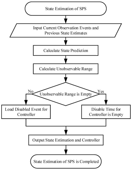
Figure 2.
State estimation flowchart.
The state estimation in an SPS is integrated with fault-tolerant control. The local controller of a subsystem first detects damaged communication lines for some devices within its region, where the controller is unaware of the information about these devices. Subsequently, the controller initiates a state estimation algorithm. Using the information provided for the damaged device and the system’s pre-fault state, the controller infers the possible current state of the system, considering this as the current state of the system. Fault-tolerant control is then applied, restricting the subsystem to legal states by controlling controllable events within the subsystem. This prevents the system from entering invalid states and potentially leading to a system collapse.
3.2. State Estimation under Partial Observability
In the fault recovery operation of an SPS, there are observable events (such as sensor readings) and unobservable events (such as line faults, communication failures, or sensor damage). Therefore, after a fault occurs, fault estimation needs to be performed on the SPS, determining the type of fault based on a series of observable event sequences to take appropriate measures.
The definition of the projection operator is given by the mapping from the event sequence set to the set of observable event sequences , as follows:
where is the set of observable events and is the set of unobservable events for any event sequence and for any event , .
The inverse projection mapping of the projection operator: .
To determine whether a system is diagnosable, the following two assumptions are established:
- The system’s language is live, meaning that every state in the system has at least one corresponding state transition function;
- There are no closed-loop paths consisting solely of unobservable events in the system:
Based on these assumptions, the diagnosability of the system is defined:
If there exists an unobservable event that is diagnosable under the mapping if and only if
where represents the last event of the path and represents a suffix of .
The diagnosability condition function D: is defined as follows:
Diagnosability can be described as follows: let be a sentence of the system, be the fault event, and t be any sufficiently long suffix of . If for all paths with the same mapping as , the fault event is included, then the event is diagnosable. In other words, when a fault occurs in the system, the occurrence of the fault event can be determined by observing the system’s output.
In particular, if all fault events in the system are diagnosable, then the system is diagnosable.
With the definition of diagnosability and the extended hybrid automaton, the fault-determined state is defined as the following:
Therefore, by determining whether a fault has occurred, the current state of the system can be estimated, providing the current state for subsequent subsystem control and global control.
Due to the presence of unobservable events, system state estimation needs to be performed based on observable event sequences to determine the current state of the system.
When observable events occur, the system needs to first calculate the possible states that the system can directly reach, represented by the observable range :
where is the previous state estimate of the current state estimate and is an observable event. The state prediction value is .
Finally, calculate and , where is the set of states that the system can reach from through some unrestricted unobservable events. The definition of the unobservable range is as follows:
Thus, by the observable events that occur in the system, state estimation can be obtained. If, according to the state estimation, it is determined that the current state is likely to lead the system to an invalid state, fault-tolerant control from the previous section is applied, disabling controllable events that can enter the set to ensure that the system always stays in a safe state. Otherwise, no action is taken. When the system’s elements are all recoverable after state estimation, recovery events can be triggered to return the system to a normal structure. The recoverable condition under partial observability is given by the following:
4. Simulation and Results Analysis
An illustrative analysis of state estimation in observable segments of the SPS is conducted in this section. A simulation of the actual state of equipment post-system malfunction is performed, followed by a comparative analysis with conventional fault localization algorithms.
The simulation system comprises two main turbine generators (MTGs), each rated for 36 MW, three auxiliary turbine generators (ATGs), each rated for 4 MW, and one backup diesel generator (BDG), rated for 0.5 MW. The generator units are linked to power conversion modules (PCMs), enabling each power generation module (PGM) to supply power independently or simultaneously to both port and starboard busbars. Power distribution occurs through both port and starboard longitudinal medium voltage (MV) buses, operating at 5 kV DC.
As for the loads, the system includes two propulsion loads, two radar loads, one pulse load, and four load centers. The largest loads within the system are the port and starboard propulsion motor modules (PMMs), each demanding 36 MW, although they typically function at substantially lower power levels during normal operations. Internally, the load centers are divided into vital loads (VL), semi-vital loads (SL), and non-vital loads (NL). The interconnection of internal equipment within the system can be independently controlled through internal circuit breakers within the devices.
Table 1 displays the component specifications of the SPS under study, whose detailed parameters can be found in [23].

Table 1.
SPS equipment parameters.
The fault locations for the case study are marked in Figure 3.
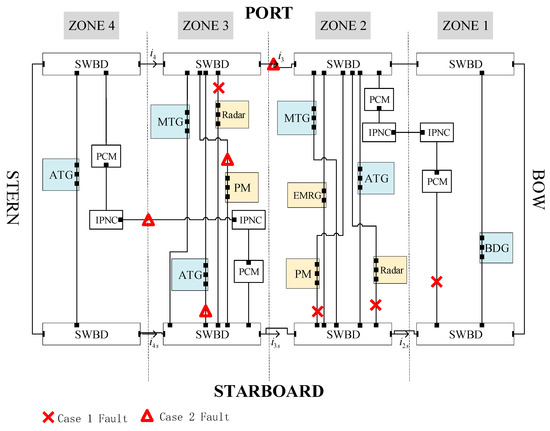
Figure 3.
SPS case study fault setting.
The simulation was performed on a MATLAB 2017 b platform and a Windows 10 operating system, utilizing an i7-6500U CPU @2.50 GHz 2.60 GHz processor and 4.00 GB of memory. The initial simulation state was established with all components operating at rated power, except for the standby generator and pulse load. The total simulation time was set to 8 s and the step size was set to 10−4 s.
4.1. Case 1
For clarity, the analysis begins with Zone 1. This zone includes two types of devices: standby generators and a load center. As the standby generator is in standby mode, it does not affect the system in this scenario. Consequently, the simplified Zone 1 only includes the load center. To clarify the operational state of Zone 1, symbols “1”, “2”, and “3” are used to denote the connection status of the load center: “1” indicates the load center is not connected to the bus (unloaded state), “2” indicates connection to Zone 2, and “3” indicates connection to the starboard bus. Additionally, three digits represent the internal connection status of the load center: “1” for load offline, “2” for primary load online, and “3” for secondary load online. Thus, the discrete states of the load center in Zone 1 result in 3 × 2 × 2 × 2 = 24 states. For instance, if Zone 1’s state is “3222”, it signifies that the load center is connected to the starboard, the second digit “2” represents that important loads are online in the load center, the third digit “2” represents that secondary loads are online in the load center, and the fourth digit “2” represents that general loads are online in the load center.
In addition, control events need to be defined, as shown in Table 2.

Table 2.
Load center control event list.
In Case 1, it is assumed that the SPS experiences an impact and a fault occurs in the fifth second of system operation. After detecting the fault, the system enters a fault operation structure, and the assumed fault positions are the left busbar branch of the radar in Zone 3, the right busbar branch of the propulsion load and radar in Zone 2, and the right busbar branch of the load center in Zone 4. The fault locations are marked in Figure 3.
Based on the previous analysis, the invalid states are calculated:
These invalid states are derived based on load priorities. Therefore, any state in Zone 1 that includes the last three states “112”, “121”, “122”, and “212” is considered invalid. Similarly, when the load center is offline, states with any load status other than “1” are considered invalid. These invalid states are updated when a fault occurs, increasing due to the emergence of fault-induced invalid states.
If sensor damage occurs after a fault, rendering device status information unobservable, and the controller cannot obtain valid information like current and voltage, the previously described state estimation algorithm is required. For ease of description, assuming fault-induced invalid states are eliminated through fault-tolerant control, the state transition of Zone 1 after moving to the fault structure can be presented as shown in Figure 4.
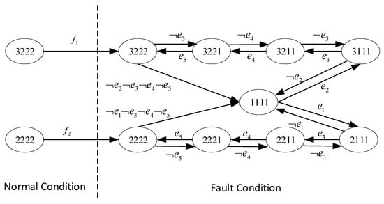
Figure 4.
The discrete state transition diagram of Zone 1.
Assuming an initial state , a fault occurs at time 5 s, and a communication fault causes unknown device status, as the fault is unobservable and uncontrollable, the state estimation at this point is . Subsequently, with an observation of event , which is the inverse process of event , the estimated state of the system becomes . Since the control algorithm identifies as an invalid state, the controller continues the state estimation. Based on the initial state and the first estimation , the subsequent state estimation is .
Considering Zone 1’s initial state as “3222” and its transition to “1111” after a power supply branch failure, states previously powered by the faulty branch are deemed invalid. The updated set of invalid states is the following:
Therefore, the reachable state set for Zone 1 is the following:
The reachable states mentioned above exclude the states that begin with “3”, indicating that using the starboard power supply for load centers is an invalid state after a fault occurs.
Similar to Zone 1, the state estimation process for other zones follows a comparable procedure. The state estimation for Case 1 is summarized in Table 3.

Table 3.
Simulation results for Case 1 state estimation.
Table 3 reveals that the state estimation time for Zone 1 is significantly less than for Zones 2 and 3. This discrepancy is attributed to the lower number of states in subsystem 1, resulting in a smaller search space for the controller and, consequently, a reduced computation load. The state estimation times for Zones 2 and 3 are comparable due to their similar state counts. However, since Zone 4 does not experience a fault, the controller does not perform a state estimation for this zone, as indicated in Table 3.
After the occurrence of the specified faults in the SPS, the system undergoes disturbances. To comprehensively understand the actual impact of the faults on the system, Figure 5 depicts the real-time operation of the system from 0 to 8 s under fault conditions.
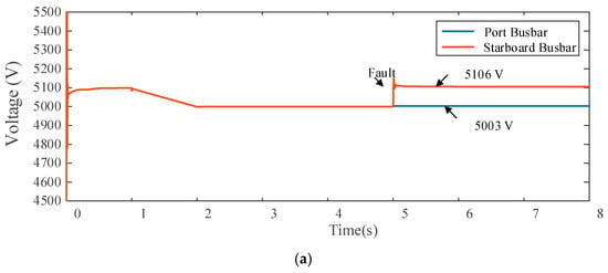
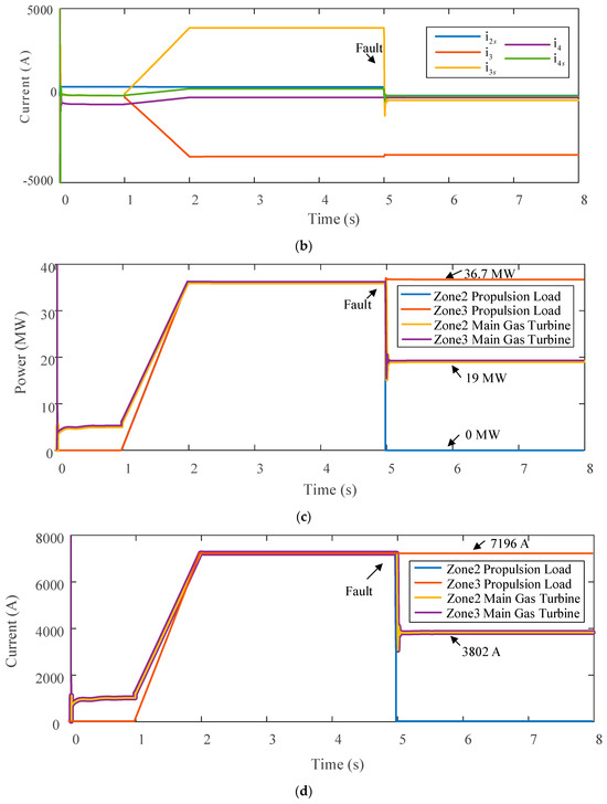
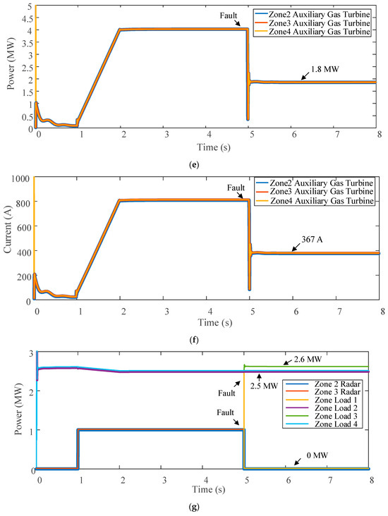
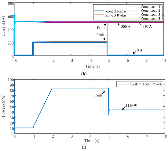
Figure 5.
Operation status of the SPS under the fault condition in Case 1. (a) Busbar voltage. (b) Busbar current. (c) Main generator and propulsion motor power. (d) Main generator and propulsion motor current. (e) Auxiliary generator power. (f) Auxiliary generator current. (g) Radar and regional load power. (h) Radar and regional load current. (i) System total power.
Compared to the normal operation of the SPS before the fault occurrence at 5 s, Figure 5 illustrates a substantial impact of the simultaneous faults at the 5 s mark. In the aftermath of the fault at 5 s, as shown in Figure 5a, the sudden disconnection of the load causes voltage fluctuations in both left and right busbars. The impact on the left busbar is minimal, resulting in a fluctuation of around a dozen volts, while the right busbar experiences a significant disturbance of approximately 160 V. Subsequently, the system self-adjusts, with the busbar voltages quickly returning to stability. However, due to the offline status of the high-power propulsion load in Zone 2, the right busbar voltage eventually stabilizes at around 5100 V, while the left busbar voltage remains around 5000 V. As shown in Figure 5b, the fault-induced load disconnection causes a drop in busbar current i3s, with a maximum fluctuation of about 4 kA. Other busbar currents at different locations do not exhibit significant changes.
For generator sets, as shown in Figure 5c, the power changes in the two main gas turbine units are almost identical. At the moment of the fault, the output power experiences a brief increase, followed by a rapid decline to around 15 MW, ultimately stabilizing at approximately 19 MW. As shown in Figure 5e, the power trends for the three auxiliary gas turbine units resemble those of the main gas turbines, with a transient increase followed by a swift decrease, stabilizing at around 1.8 MW. For load devices, as shown in Figure 5c, after the fault, the high-power propulsion load in Zone 2 goes offline, consuming zero power. The propulsion load in Zone 3, however, experiences a sudden rapid increase in power consumption due to busbar voltage fluctuations, stabilizing at a level greater than 36 MW. However, as shown in Figure 5g, the radar load changes are relatively simple, with both radars going offline after the fault, consuming zero power. Additionally, after the fault, the load center in zone 1 goes offline, reducing power consumption to zero, while the load centers in the other three zones exhibit transient fluctuations before returning to stability. Since the load center in Zone 3 is connected to the right busbar, its power fluctuates significantly, while the other zones maintain power consumption levels similar to those before the fault. The overall system power curve is shown in Figure 5i, following a trend similar to that of the generator units. The system stabilizes at approximately 44 MW. From Figure 5d,f,h, it is evident that the curves of equipment currents within the system closely resemble the power curves.
4.2. Case 2
With an unchanged initial state, faults are assumed to occur at the fifth second. After detecting the fault, the system enters the fault structure, and the assumed fault locations are the left busbar branch of the distribution board from Zone 2 to Zone 3, the branch connecting the propulsion load in Zone 3 to the left busbar, the branch connecting the auxiliary engine to the right busbar, and the line connecting the load center from Zone 3 to Zone 4. The fault locations are marked in Figure 3. To comprehensively understand the actual impact of the faults on the system, Figure 6 depicts the real-time operation of the system from 0 to 8 s under fault conditions.
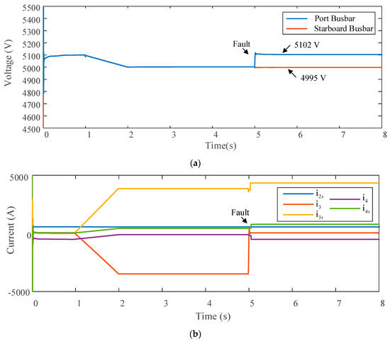
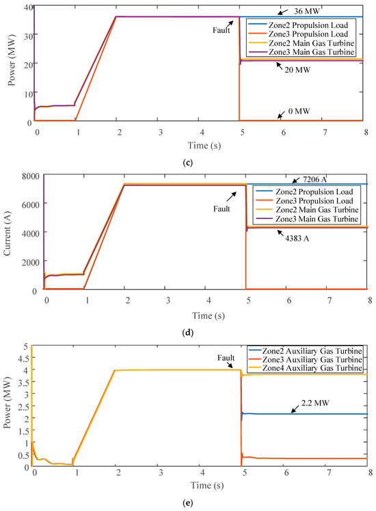
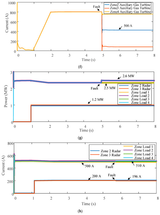
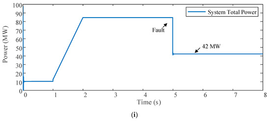
Figure 6.
Operation status of the SPS under the fault condition in Case 2. (a) Busbar voltage. (b) Busbar current. (c) Main generator and propulsion motor power. (d) Main generator and propulsion motor current. (e) Auxiliary generator power. (f) Auxiliary generator current. (g) Radar and regional load power. (h) Radar and regional load current. (i) System total power.
The port bus is split into two halves with no connection between the left and right sides. The propulsion load in Zone 2 is powered by an adjacent region, maintaining a power output of 36 MW before and after the fault. In Zone 3, the propulsion load is powered by a non-adjacent region, with power output at 36 MW before the fault and 0 MW after. The main gas turbine in Zones 2 and 3, powering non-adjacent regions, operated at 36 MW before the fault and reduced to 20 MW after. The auxiliary gas turbine in Zone 2, supplying a non-adjacent region, reduced to 2.2 MW after the fault. Zone Load 3, powering an adjacent region, maintained a power output of 2.5 MW before and after the fault, while Zone Load 4, supplying a non-adjacent region, decreased to 2.6 MW after the fault. Consequently, the total system power after the fault is 42 MW.
The state estimation for Case 4.2 is presented in Table 4.

Table 4.
Simulation results of Case 2 state estimation.
Table 4 shows that, due to the significantly larger number of states in Zone 3 compared to Zone 4, the state estimation time for Zone 3 is much greater than that for Zone 4. This observation aligns with the findings from Case 1. In combining the results from Cases 1 and 2, it is evident that local controllers can independently perform state estimation tasks without interference from other controllers or coordinators. Moreover, the computation time is mainly determined by the number of states within the subsystem, showcasing the independence of each controller in performing its task.
4.3. Comparison and Discussion
The state estimation method compares with the commonly used centralized fault localization method (genetic algorithm). All results are based on computations conducted on a computer equipped with an Intel i7-6500U processor and 4 GB of memory, using Matlab 2017b software. For the genetic algorithm’s state estimation, a population size of 200 and termination evolution generation of 400 are set, with crossover probability at 0.9 and mutation probability at 0.06.
Table 5 presents the fault location results for Cases 1 and 2. As the compared algorithm employs a centralized approach, fault location is considered from a holistic perspective, resulting in the total runtime being the only information provided in Table 5.

Table 5.
Traditional fault location calculation results.
The first 20 nodes in Table 5 reflect the current status of equipment within the system, while the last 5 nodes indicate busbar currents. A value of “0” signifies normal current at the node, “1” represents abnormal current, and “2” denotes reverse-directional abnormal current. The table reveals that, when the SPS experiences a fault with sensor damage, rendering the controller unaware of device information at the fault location, the controller relies on busbar current to infer faults within the system. However, the computed results, indicating faults between Zone 3 and Zone 4 for Case 1 and between Zone 2 and Zone 3 for Case 2, may not be accurate and could potentially be incorrect.
Comparing Table 3 and Table 4, it is evident that when the system is partially observable, it is still possible to infer the system’s state from information about other devices, thereby preparing for subsequent state recovery. In terms of computation time, the proposed state estimation method is two orders of magnitude faster than traditional fault localization methods, mainly because genetic algorithms involve iterative calculations across the population, significantly extending the computation time. Additionally, centralized computing methods need to consider the entire system, leading to an exponential increase in data volume with growing system states, resulting in increased computation time. In contrast, the distributed method divides the system states into different subsystems, significantly reducing the computational load on controllers and thus achieving relatively faster computation times.
In the following discussion, different state estimation methods are compared from different aspects: configuration, fault type, number of faults, simulation platform, and computation time. The results are shown in Table 6. It can be seen that most state estimate studies focus solely on electrical faults or communication faults, and our approach is capable of handling both. This capability enhances the applicability and robustness of the proposed method in complex, real-world scenarios. Furthermore, while other methods exhibit computation times ranging from 0.1 s to above 2.4 s, the proposed distributed approach achieves a computation time of approximately 0.001 s. This efficiency is crucial for real-time applications and quick response in fault detection and resolution.

Table 6.
Comparison of different state estimation methods.
In summary, the proposed state estimation algorithm demonstrates lower computational overhead and faster processing speed. It does not burden controllers significantly, and the method can compute fault locations in partially observable system conditions, providing a novel approach to fault localization.
5. Conclusions
This paper introduces an innovative approach for state estimation in an SPS under partial observability, emphasizing the integration of distributed fault-tolerant control mechanisms. The fault localization method, achieved through fault-tolerant control, prevents subsystems from entering invalid states. Under the conditions of partial observability, it rapidly and accurately identifies the location of faults, thereby providing correct fault location information for subsequent fault control algorithms in search of optimal solutions. The case studies’ results indicate that the proposed algorithm is approximately two orders of magnitude faster than traditional fault localization methods based on genetic algorithms. It accurately and swiftly identifies fault locations even in the event of communication failures, where traditional methods fail to correctly determine the fault points.
As an extension of our work, future research will focus on integrating advanced fault prediction technologies into an SPS, which aims to significantly enhance the systems’ ability to manage and mitigate complex, concurrent fault scenarios, thereby elevating the overall reliability and efficiency of an SPS in an increasingly digital and interconnected era.
Author Contributions
Conceptualization, W.Z. and Z.L.; methodology, W.Z.; software, T.G.; validation, W.Z., T.G. and Z.L.; formal analysis, W.Z.; investigation, W.Z.; resources, W.Z. and J.W.; data curation, Z.L. and J.W.; writing—original draft preparation, T.G.; writing—review and editing, W.Z.; visualization, Z.L.; supervision, W.Z.; project administration, W.Z.; funding acquisition, W.Z. and J.W. All authors have read and agreed to the published version of the manuscript.
Funding
This research was funded by the Jiangsu Province Graduate Innovation Program Project, SJCX23_2130.
Institutional Review Board Statement
Not applicable.
Informed Consent Statement
Not applicable.
Data Availability Statement
The data presented in this study are available on request from the corresponding author.
Conflicts of Interest
The authors declare no conflict of interest.
References
- Zhu, X.; Wang, K.; Yang, J.; Huang, L.; Shen, B.; Sun, M. Research on the control strategy of grid connection between shore power supply and ship power grid. Energy Rep. 2022, 8, 638–647. [Google Scholar] [CrossRef]
- Yang, S. Research on Design, Detection and Realization of Monitoring System Based on Ship Power Grid Parameter. J. Phys. Conf. Ser. 2021, 2023, 012048. [Google Scholar] [CrossRef]
- Hannaford, E.; Maes, P.; Van Hassel, E. Autonomous ships and the collision avoidance regulations: A licensed deck officer survey. WMU J. Marit. Aff. 2022, 21, 233–266. [Google Scholar] [CrossRef]
- Gallo, M.; Kaza, D.; D’Agostino, F.; Cavo, M.; Zaccone, R.; Silvestro, F. Power plant design for all-electric ships considering the assessment of carbon intensity indicator. Energy 2023, 283, 129091. [Google Scholar] [CrossRef]
- Di, P.; Cheng, Y.; Pan, S.; Fan, X.; Zhan, W.; Gang, Y. Testability Modelling and Optimization Technology of Ship Electrical Equipment Based on Multi-Signal Flow Diagram. IOP Conf. Ser. Mater. Sci. Eng. 2021, 1043, 022057. [Google Scholar] [CrossRef]
- Zhu, J.; Wang, L.; Zhang, D. Research on Ship Fault Diagnosis Based on Deep Learning. IOP Conf. Ser. Mater. Sci. Eng. 2020, 793, 012035. [Google Scholar] [CrossRef]
- Cossentino, M.; Sabatucci, L.; Zaffora, F. Safety Management in Smart Ships. In Proceedings of the Internet and Distributed Computing Systems: 12th International Conference, Naples, Italy, 10–12 October 2019; pp. 328–337. [Google Scholar]
- Ding, T.; Qu, M.; Wu, X.; Qin, B.; Yang, Y.; Blaabjerg, F. Defense strategy for resilient shipboard power systems considering sequential attacks. IEEE Trans. Inf. Forensics Secur. 2020, 15, 3443–3453. [Google Scholar] [CrossRef]
- Zhang, T.; Wu, D.; Li, L.; Yamashita, A.S.; Huang, S. A fault reconfiguration strategy based on adjustable space operator discrete state transition algorithm for ship microgrid system. Electr. Power Syst. Res. 2022, 205, 107707. [Google Scholar] [CrossRef]
- Zeng, C. Intelligent Retrieval System of Ship Fault Information Based on Big Data Analysis. J. Coast. Res. 2020, 103, 882–886. [Google Scholar] [CrossRef]
- Lou, H. Massive Ship Fault Data Retrieval Algorithm Supporting Complex Query in Cloud Computing. J. Coast. Res. 2019, 93, 1013–1018. [Google Scholar] [CrossRef]
- Zhang, L.; Zhang, Z.; Peng, H. Diagnostic Method for Short Circuit Faults at the Generator End of Ship Power Systems Based on MWDN and Deep-Gated RNN-FCN. J. Mar. Sci. Eng. 2023, 11, 1806. [Google Scholar] [CrossRef]
- Zhang, S. Large-scale Ship Fault Data Retrieval Algorithm Supporting Complex Query in Cloud Computing. J. Coast. Res. 2019, 97, 236–241. [Google Scholar] [CrossRef]
- Babaei, M.; Shi, J.; Abdelwahed, S. A survey on fault detection, isolation, and reconfiguration methods in electric ship power systems. IEEE Access 2018, 6, 9430–9441. [Google Scholar] [CrossRef]
- Zhang, Y.; Yang, T.; Tang, Z. Active fault-tolerant control for load frequency control in multi-area power systems with physical faults and cyber attacks. Int. Trans. Electr. Energy Syst. 2021, 31, e12906. [Google Scholar] [CrossRef]
- Ni, K.; Gan, C.; Peng, G.; Shi, H.; Hu, Y.; Qu, R. Power Compensation-Oriented SVM-DPC Strategy for a Fault-Tolerant Back-to-Back Power Converter Based DFIM Shipboard Propulsion System. IEEE Trans. Ind. Electron. 2021, 69, 8716–8726. [Google Scholar] [CrossRef]
- Ni, K.; Gan, C.; Hu, Y. Direct power control of fault-tolerant converter-based doubly-fed induction machine electric drivetrain for ship propulsion. In Proceedings of the 2020 23rd International Conference on Electrical Machines and Systems (ICEMS), Hamamatsu, Japan, 24–27 November 2020; IEEE: Piscataway, NJ, USA, 2020; pp. 1269–1274. [Google Scholar]
- Kuppusamy, S.; Joo, Y.H.; Kim, H.S. Fault-tolerant load frequency control for DFIG-based interconnected wind power systems. Inf. Sci. 2022, 582, 73–88. [Google Scholar] [CrossRef]
- Gao, J.; Yang, X.; Huang, J.; Peng, K. A data-driven fault detection and fault-tolerant control scheme for large-scale systems and its application on multi-area interconnected power systems. IET Control Theory Appl. 2023, 17, 400–418. [Google Scholar] [CrossRef]
- Zhu, W.; Shi, J.; Zhi, P.; Fan, L.; Lim, G.J. Distributed reconfiguration of a hybrid shipboard power system. IEEE Trans. Power Syst. 2021, 36, 4–16. [Google Scholar] [CrossRef]
- Lukas, K.; Astrid, B.; Richard, H. Optimal Design of a Distributed Ship Power System with Solid Oxide Fuel Cells under the Consideration of Component Malfunctions. Appl. Energy 2022, 316, 119052. [Google Scholar]
- Zhu, W.; Jin, C.; Liang, Z. Hybrid Modeling and Simulation for Shipboard Power System Considering High-Power Pulse Loads Integration. J. Mar. Sci. Eng. 2022, 10, 1507. [Google Scholar] [CrossRef]
- Zhu, W.; Shi, J.; Abdelwahed, S. End-to-end system level modeling and simulation for medium-voltage DC electric ship power systems. Int. J. Nav. Archit. Ocean Eng. 2018, 10, 37–47. [Google Scholar] [CrossRef]
- Alcala-Gonzalez, D.; García del Toro, E.M.; Más-López, M.I.; Pindado, S. Effect of distributed photovoltaic generation on short-circuit currents and fault detection in distribution networks: A practical case study. Appl. Sci. 2021, 11, 405. [Google Scholar] [CrossRef]
- Lv, X.; Yuan, L.; Cheng, Z.; Yin, B.; He, Y.; Ding, C. A subsystem-based fault location method in distribution grids by sparse measurement. IET Gener. Transm. Distrib. 2023, 17, 5016–5026. [Google Scholar] [CrossRef]
- Li, Y.; Wei, X.; Lin, J.; Niu, G. A robust fault location method for active distribution network based on self-adaptive switching function. Int. J. Electr. Power Energy Syst. 2023, 148, 109007. [Google Scholar] [CrossRef]
- Perez, R.; Vásquez, C.; Viloria, A. An intelligent strategy for faults location in distribution networks with distributed generation. J. Intell. Fuzzy Syst. 2019, 36, 1627–1637. [Google Scholar] [CrossRef]
- Cordova, J.; Faruque, M.O. Fault location identification in smart distribution networks with distributed generation. In Proceedings of the 2015 North American Power Symposium (NAPS), Charlotte, NC, USA, 4–6 October 2015; IEEE: Piscataway, NJ, USA, 2015; pp. 1–7. [Google Scholar]
Disclaimer/Publisher’s Note: The statements, opinions and data contained in all publications are solely those of the individual author(s) and contributor(s) and not of MDPI and/or the editor(s). MDPI and/or the editor(s) disclaim responsibility for any injury to people or property resulting from any ideas, methods, instructions or products referred to in the content. |
© 2023 by the authors. Licensee MDPI, Basel, Switzerland. This article is an open access article distributed under the terms and conditions of the Creative Commons Attribution (CC BY) license (https://creativecommons.org/licenses/by/4.0/).