
Re-Distribution of Welding Residual Stress in Fatigue Crack Propagation Considering Elastic–Plastic Behavior


Abstract
:1. Introduction
2. Experimental Procedure
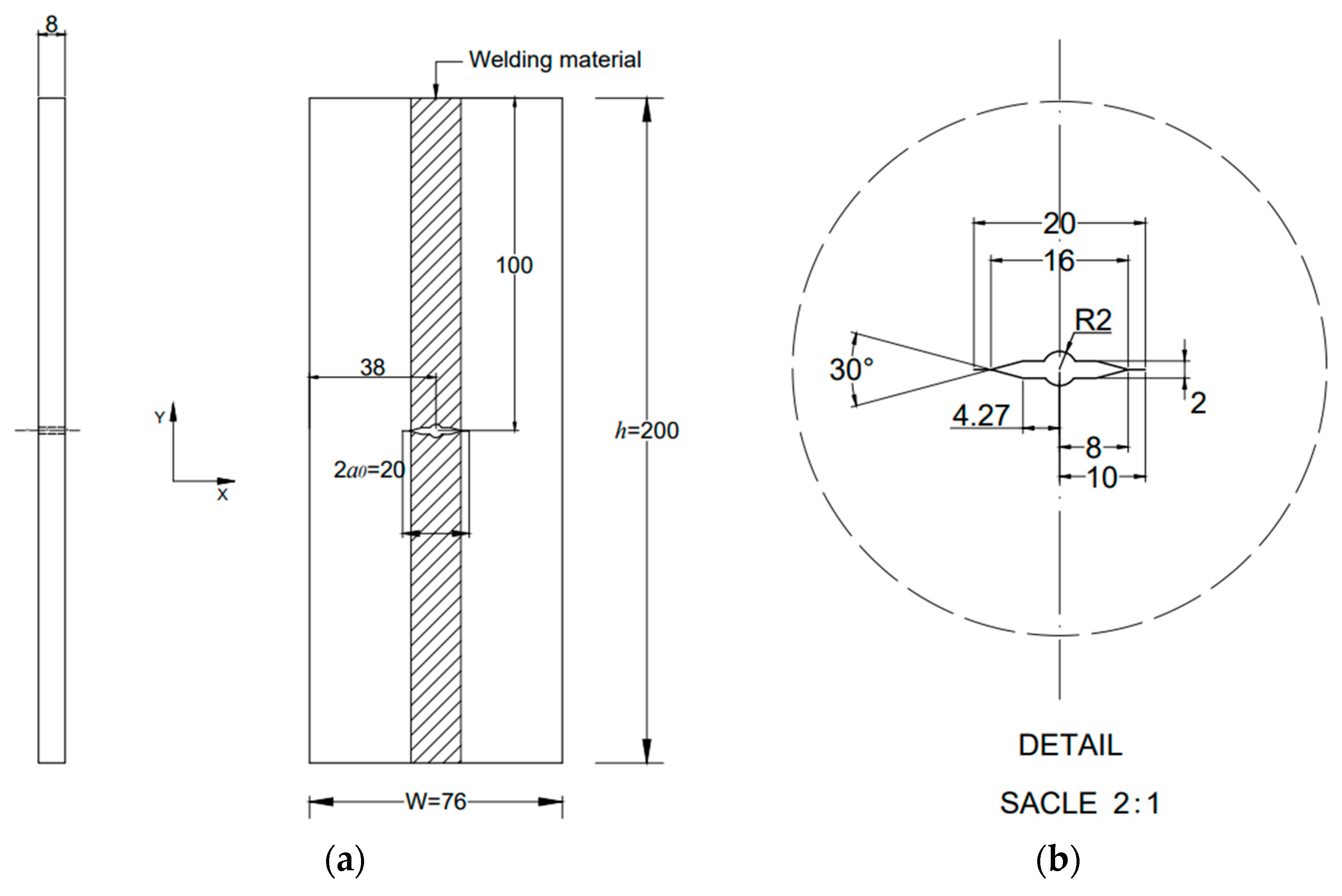
2.1. Material and Main Dimensions of Specimens
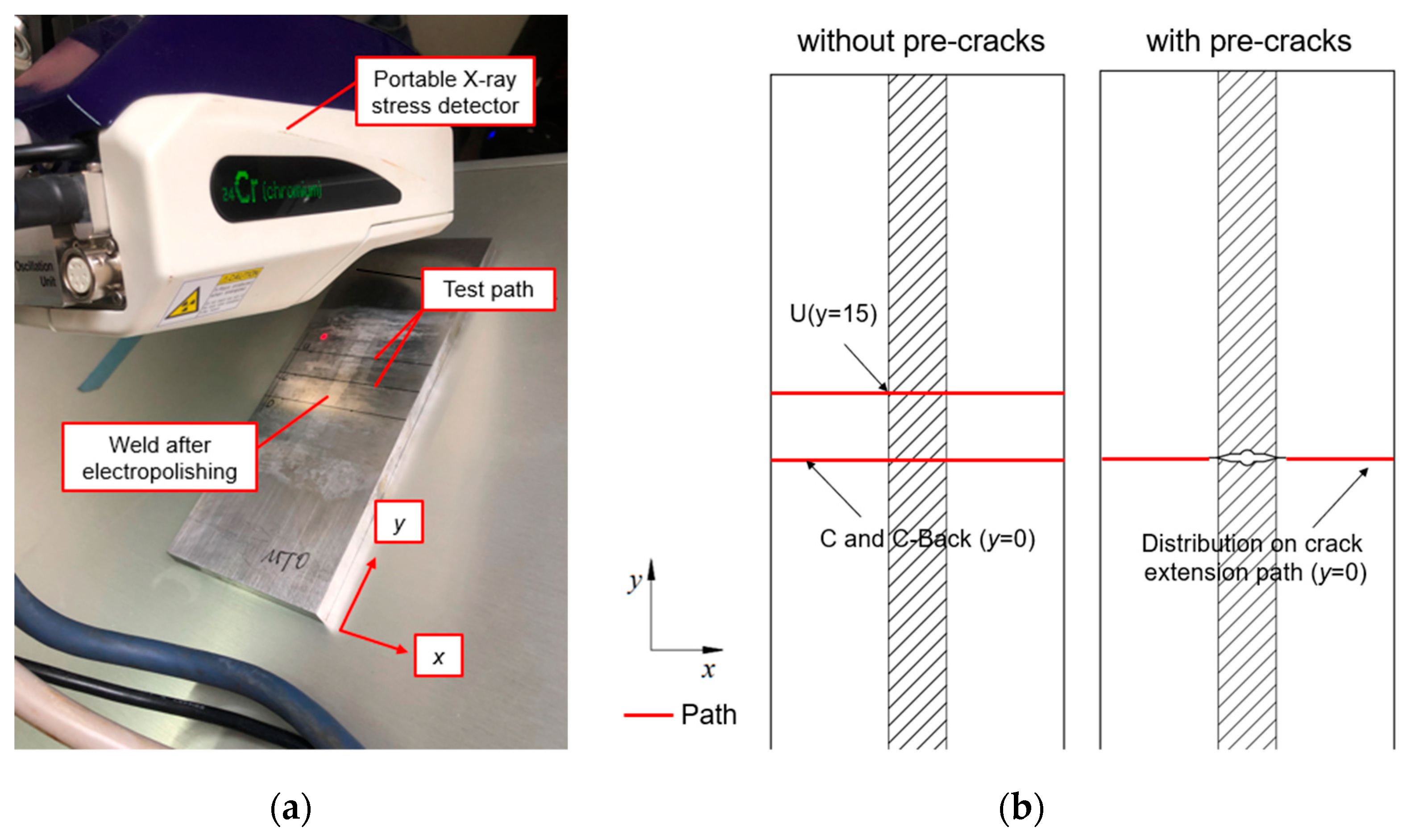
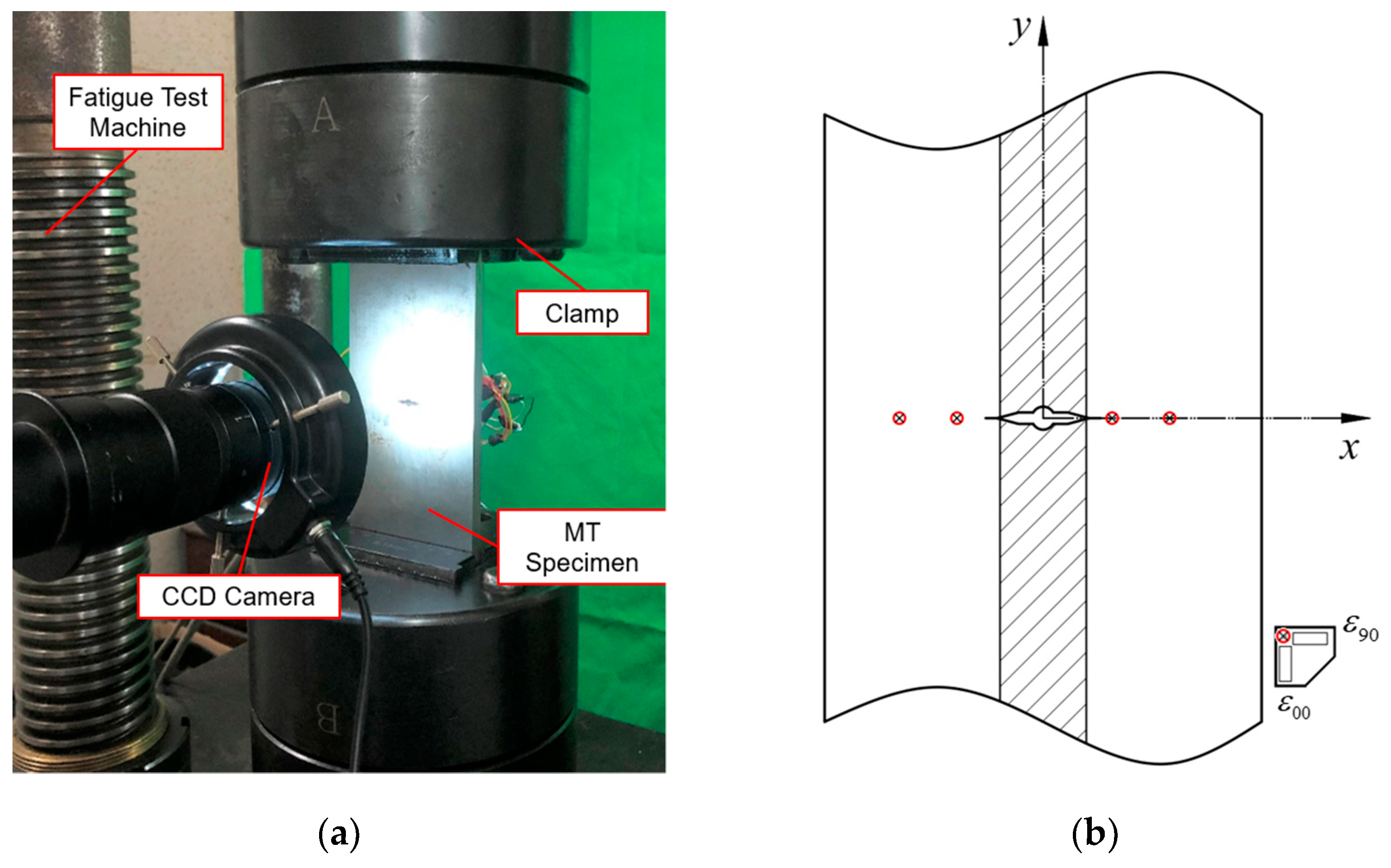
2.2. Test Setup
2.3. Experimental Results and Discussion
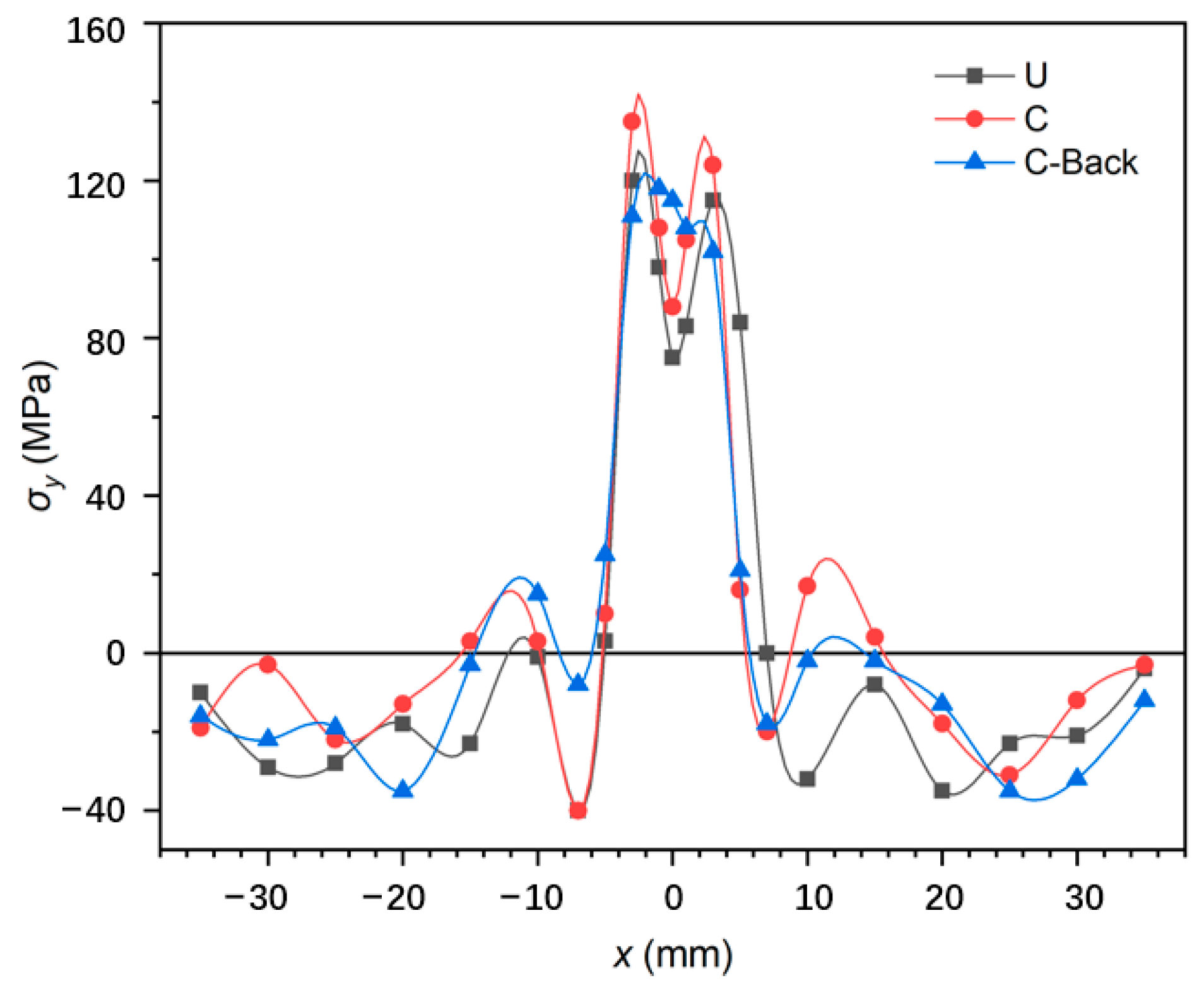
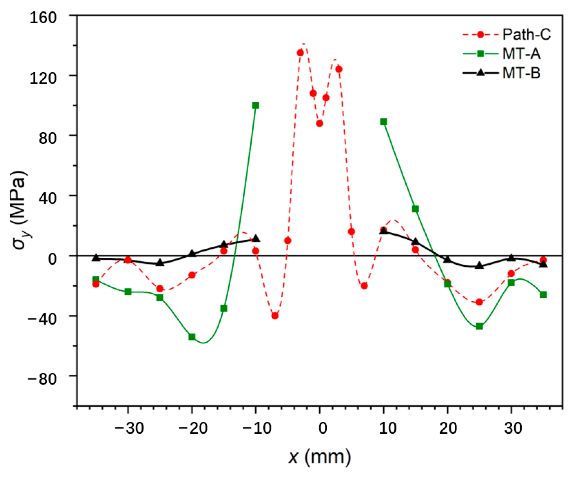
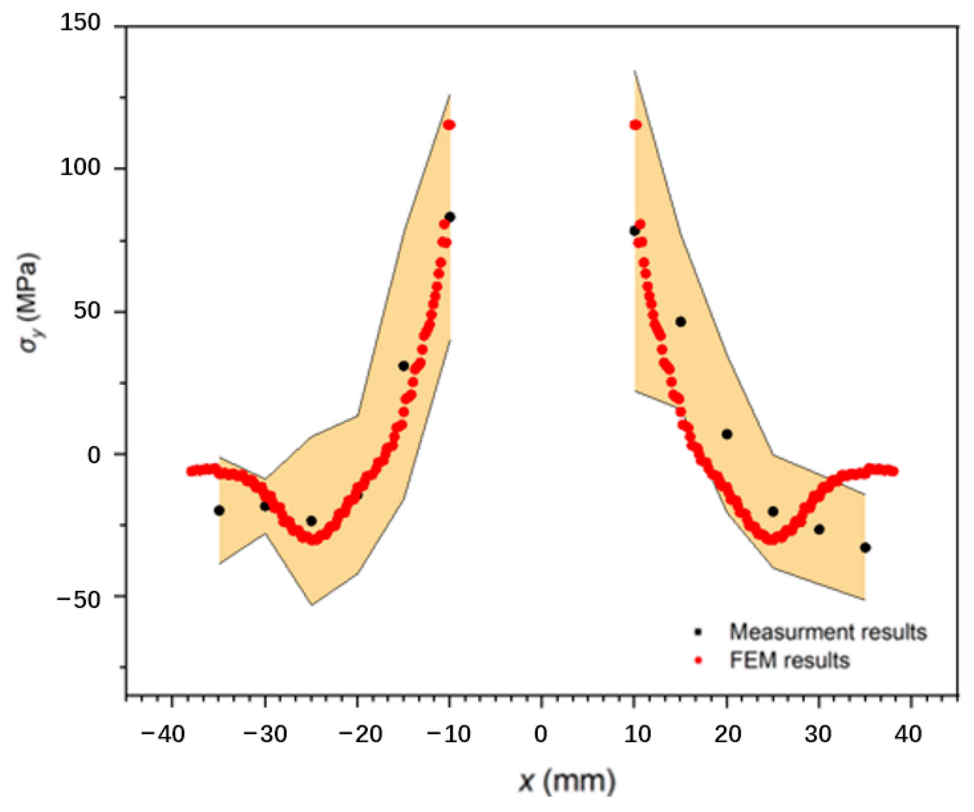
2.3.1. Distribution of Initial Welding Residual Stress
2.3.2. Welding Residual Stress Re-Distribution Calculation
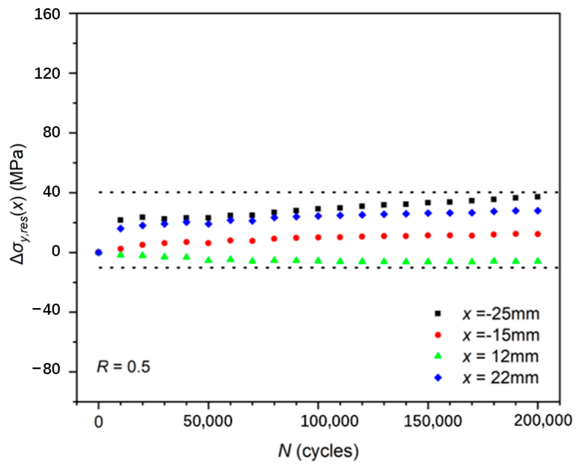
2.3.3. Impact of Cyclic Loading on Residual Stress Distribution
3. Finite Element Analysis
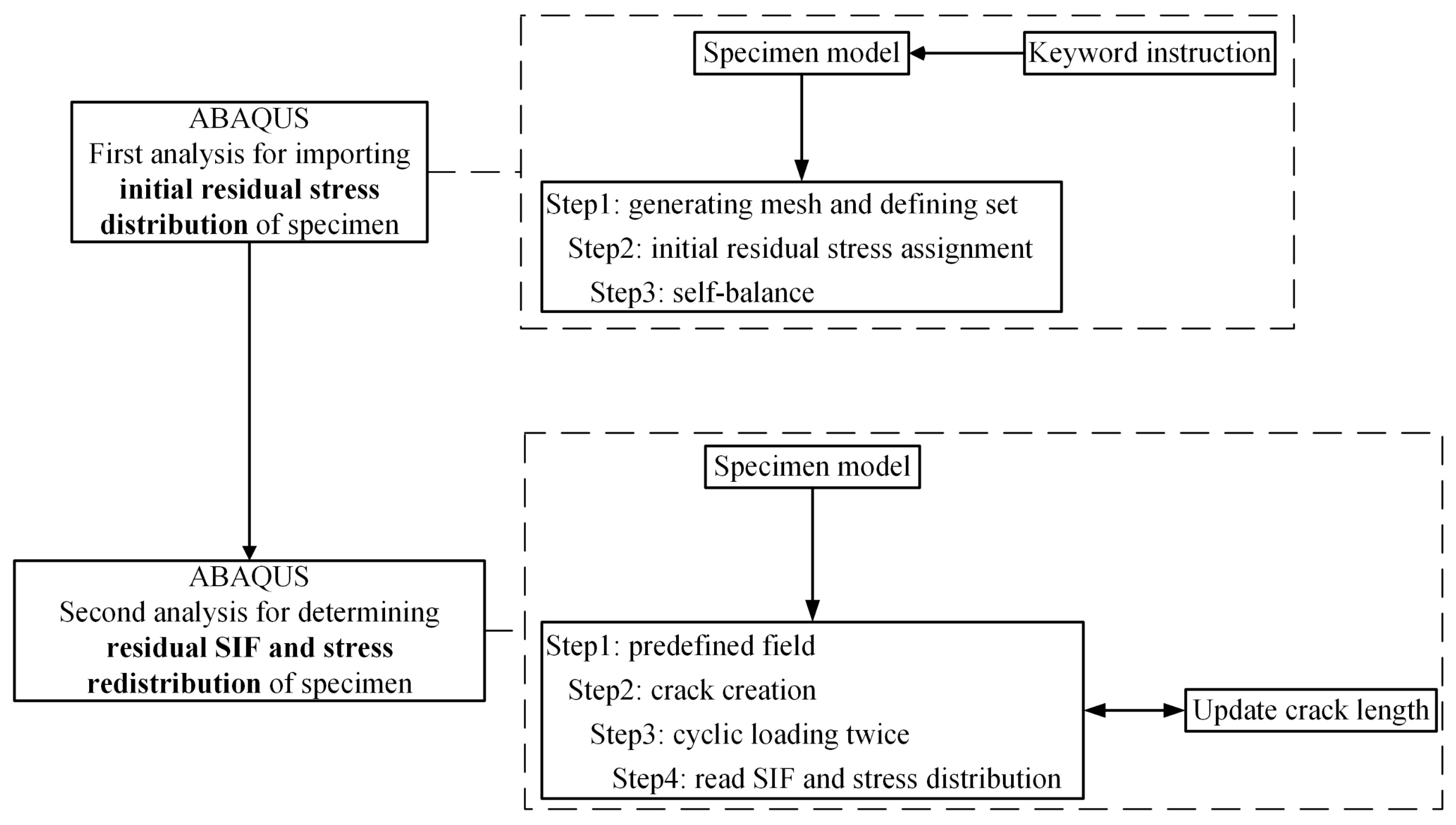
3.1. Import of Initial Welding Residual Stress
3.2. Residual Stress Intensity Factor Kres by XFEM
- Import the initial stress distribution into the FE model (in Section 3.1).
- Calculate the stress–strain value for the first crack increment step under cyclic loadings, although all elements’ numbers will be kept the same following the initial increment step.
- Update the crack length according to the experimental data.
- Read the stress–strain state of each element under the previous crack length and assign it to the current model.
- Extract the Kres at the crack tip of each increment using J-integral.
3.3. Effect of Cyclic Loadings on the Simulation Results
3.4. Simulation Results and Comparison
4. Residual Stress Intensity Factor Kres
4.1. Comparison between WFM and FEM
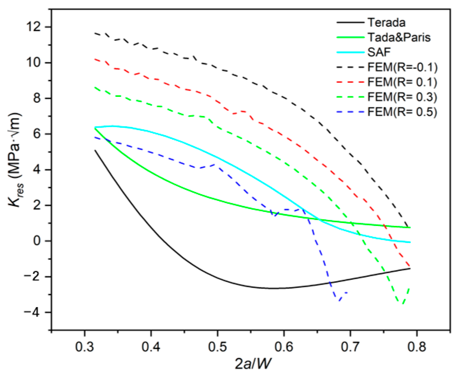
- The magnitudes of Kres predicted using WFM and the FE method are similar, all in the range of −4~12 MPa·m1/2. At the same time, WFM neglects the effect of plastic deformation on residual stress near the crack tip, resulting in a different trend.
- With the crack length increase, Kres calculated using all methods shows a decreasing trend, except for that using the Terada distribution. Combined with the initial WRS distribution in Figure 5, it is speculated that the increase in Kres may be related to the overestimation of peak compressive stress when using the Terada distribution. The Kres curve predicted using Terada distribution increased near 2a/W = 0.55, where the initial residual stress is precisely located near the right side of the compressive stress peak, raising Kres corresponding to the release of compressive stress during crack propagation.
- The calculation results of WFM depend on the choice of the initial distribution function. Weight function adopting initial distribution SAF, like that in the FE model, obtains the closest results to the simulation method. At the same time, there is a significant difference between the results of the Terada and Tada and Paris functions. This phenomenon indicates that when predicting Kres, the accuracy significantly depends on the initial distribution.
- With the increase in 2a/W, there is a significant difference between WFM and simulation results. It can be seen from Figure 15 that the trend of the Kres-2a/W curves of the WFM tends to be stable no matter what initial distribution is used. The influence of the elastic–plastic behavior of the material causes this phenomenon. When the local stress is close to the fracture limit, a significant yield area occurs on the specimen, resulting in its re-distribution behavior being entirely dominated by plasticity. Crack tips and surfaces are subjected to the compression of the plastic zone after unloading, and the K value extracted by the J-integral gradually decreases. However, WFM is based on linear elasticity assumption, considering that the residual ligament of the specimen is too short to lead to the general release of residual stress. In addition, the influence of plastic re-distribution of residual stress on crack tip is not considered in WFM. Therefore, WFM cannot predict the rapid decrease in Kres when the specimen approaches the fracture toughness.
- The Kres-2a/W curves calculated using the simulation considering the elastic–plastic response of materials show a significant stress ratio effect, which WFM cannot predict.
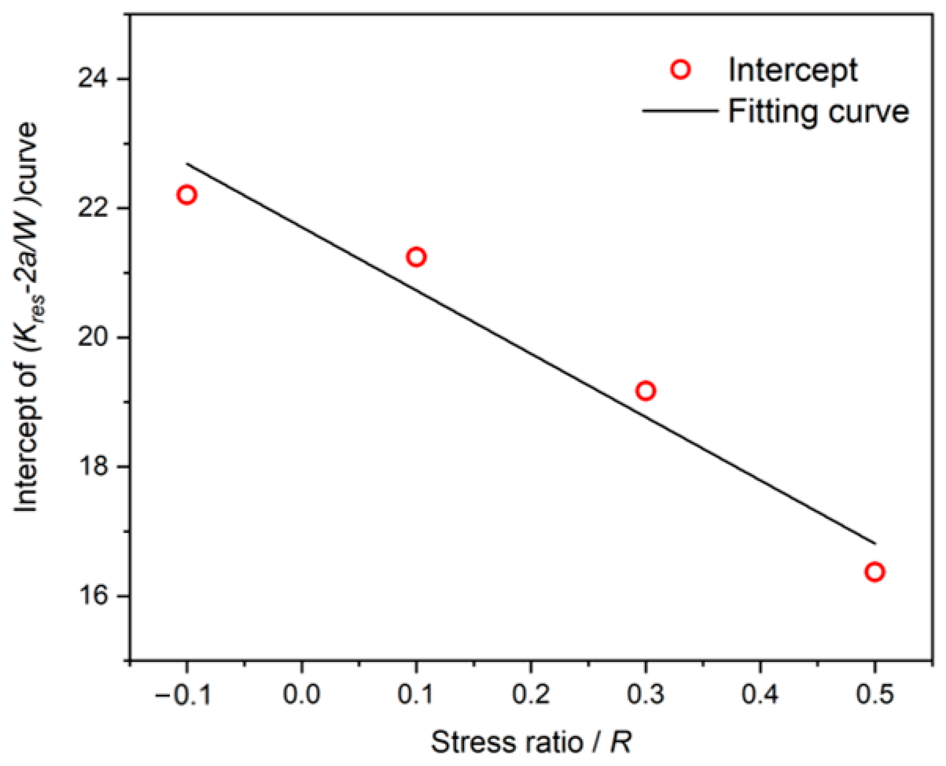
4.2. The Stress Ratio Effect of Kres
5. Conclusions
- The accuracy of the weight function method depends on the selection of the initial distribution function. Meanwhile, the stress ratio effect of Kres cannot be predicted using the weight function method.
- Terada’s re-distribution rule overestimates the increment of longitudinal residual stresses, and it is not suitable for predicting the re-distribution of residual stresses in marine high-tensile steel.
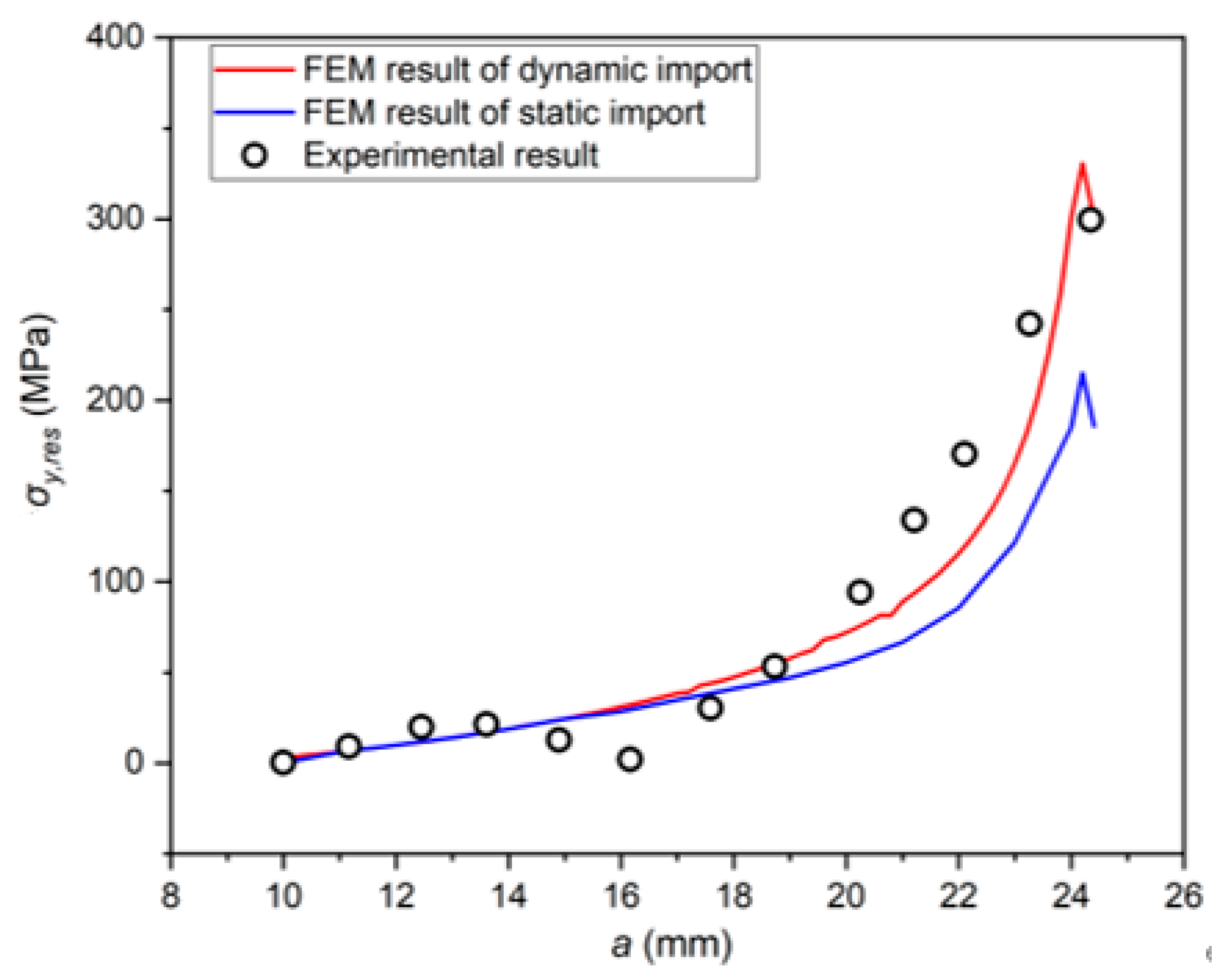
- Compared with the Terada re-distribution rule and static simulation method with initial distribution, the elastic–plastic continuous simulation method considering load timing is more consistent with the experimental measurements, which indicates that the plastic re-distribution behavior should be considered in the simulation of fatigue crack propagation.
- The Kres values calculated using elastic–plastic continuous simulation procedure indicate that Kres is affected by the crack size a/W, and exhibits a noticeable stress ratio effect when the applied stress amplitude is kept constant, which is not reflected by WFM.
- The Kres fitting model related to a/W considering the stress ratio effect is established, and the results are in good agreement with the finite element calculation results, which can better reflect the WRS plastic re-distribution behavior.
Author Contributions
Funding
Informed Consent Statement
Data Availability Statement
Conflicts of Interest
Nomenclature
| a | current crack length |
| a0 | initial crack length |
| E | Young’s modulus |
| h | specimen length |
| R | loading/stress ratio |
| W | specimen width |
| v | Poisson’s ratio |
| CT | compact tension (specimen) |
| FE(M) | finite element (method) |
| LEFM | linear elastic fracture mechanics |
| MT | middle tension (specimen) |
| SIF | stress intensity factor |
| WFM | weight function method |
| WRS | welding residual stress |
| XFEM | extended finite element method |
| C1, C2, γ1, γ2 | the Chaboche combined hardening model constants |
| Kres | residual stress intensity factor |
| ΔKeff | effective stress intensity factor range |
| σ0 | initial yield strength |
| Δσnominal | nominal stress range |
| σy | initial longitudinal welding residual stress |
| σy,0 | the maximum welding residual stress at the center line of the welding |
| σy,res | longitudinal welding residual stress |
| Δσy,res | change in longitudinal residual stress |
| σys | yield strength |
| σu | ultimate tension strength |
| h(a,x) | weight function |
References
- Adiban, S.; Ramu, M. Study on the effect of weld defects on fatigue life of structures. Mater. Today Proc. 2018, 5, 17114–17124. [Google Scholar] [CrossRef]
- Edwards, L. Influence of residual stress re-distribution on fatigue crack growth and damage tolerant design. Mater. Sci. Forum. 2008, 524–525, 363–372. [Google Scholar]
- Servetti, G.; Zhang, X. Predicting fatigue crack growth rate in a welded butt joint: The role of effective R ratio in accounting for residual stress effect. Eng. Fract. Mech. 2009, 76, 1589–1602. [Google Scholar] [CrossRef]
- Barsoum, Z.; Barsoum, I. Residual stress effects on fatigue life of welded structures using LEFM. Eng. Fail. Anal. 2009, 16, 449–467. [Google Scholar] [CrossRef]
- Lee, C.S.; Kim, M.H.; Lee, J.M.; Mahendran, M. Computational study on the fatigue behaviour of welded structures. Int. J. Plast. 2011, 20, 423–463. [Google Scholar]
- Terada, H. Stress Intensity Factor Analysis and Fatigue Behaviour of a Crack in the Residual Stress Field of Welding; ASTM International: West Conshohocken, PA, USA, 2007. [Google Scholar]
- Xu, X. Effects of Residual Stress on Surface Crack Growth at Welded Joints; Dalian University of Technology: Dalian, China, 2013. (In Chinese) [Google Scholar]
- Liljedahl, C.; Zanellato, O.; Fitzpatrick, M.; Lin, J.; Edwards, L. The effect of weld residual stresses and their re-distribution with crack growth during fatigue under constant amplitude loading. Int. J. Fatigue 2010, 32, 735–743. [Google Scholar] [CrossRef]
- Liljedahl, C.; Brouard, J.; Zanellato, O.; Lin, J.; Tan, M.; Ganguly, S.; Irving, P.E.; Fitzpatrick, M.; Zhang, X.; Edwards, L. Weld residual stress effects on fatigue crack growth behaviour of aluminium alloy 2024-T351. Int. J. Fatigue 2009, 31, 1081–1088. [Google Scholar] [CrossRef]
- Liljedahl, C.; Tan, M.; Zanellato, O.; Ganguly, S.; Fitzpatrick, M.; Edwards, L. Evolution of residual stresses with fatigue loading and subsequent crack growth in a welded aluminium alloy middle tension specimen. Eng. Fract. Mech. 2008, 75, 3881–3894. [Google Scholar] [CrossRef]
- Wang, L.; Qian, X. Welding residual stresses and their relaxation under cyclic loading in welded S550 steel plates. Int. J. Fatigue 2022, 162, 106992. [Google Scholar] [CrossRef]
- Moshtaghi, H.; Safyari, M. Effect of Work-Hardening Mechanisms in Asymmetrically Cyclic-Loaded Austenitic Stainless Steels on Low-Cycle and High-Cycle Fatigue Behavior. Steel Res. Int. 2021, 92, 2000242. [Google Scholar] [CrossRef]
- Moshtaghi, M.; Loder, B.; Safyari, M.; Willidal, M.; Hojo, T.; Mori, G. Hydrogen trapping and desorption affected by ferrite grain boundary types in shielded metal and flux-cored arc weldments with Ni addition. Int. J. Hydrogen Energy 2022, 47, 20676–20683. [Google Scholar] [CrossRef]
- E 647-08; ASTM Standard Test Method for Measurement of Fatigue Crack Growth Rates. ASTM International: West Conshohocken, PA, USA, 2015.
- Terada, H. An analysis of the stress intensity factor of a crack perpendicular to the welding bead. Eng. Fract. Mech. 1976, 8, 441–444. [Google Scholar] [CrossRef]
- Tada, H.; Paris, P.C. The stress intensity factor for a crack perpendicular to the welding bead. Int. J. Fract. 1983, 21, 279–284. [Google Scholar] [CrossRef]
- Qiang, B.; Li, Y.; Yao, C.; Wang, X. Through-thickness welding residual stress and its effect on stress intensity factors for semi-elliptical surface cracks in a butt-welded steel plate. Eng. Fract. Mech. 2018, 193, 17–31. [Google Scholar] [CrossRef]
- Perez, N. Fatigue Crack Growth. In Fracture Mechanics; Springer International Publishing: Cham, Switzerland, 2017; pp. 327–372. [Google Scholar]
- Rice, J.R. Some remarks on elastic crack-tip stress fields. Int. J. Solids Struct. 1972, 8, 751–758. [Google Scholar] [CrossRef]
- Bueckner, H. Novel principle for the computation of stress intensity factors. Z. Angew. Math. Phys. 1970, 50, 529–546. [Google Scholar]


| E/GPa | v | σys/MPa | σu/MPa | σ0/MPa | C1 | γ1 | C2 | γ2 |
|---|---|---|---|---|---|---|---|---|
| 219 | 0.35 | 635 | 688 | 565 | 66,500 | 1485 | 950 | 14.25 |
| Specimen Number | Δσnominal/MPa | R | Control Group Number |
|---|---|---|---|
| R − 0.1 | 100 | −0.1 | - |
| R0.1 | 100 | 0.1 | R0.1-B |
| R0.3 | 100 | 0.3 | R0.3-B |
| R0.5 | 100 | 0.5 | R0.5-B |
Disclaimer/Publisher’s Note: The statements, opinions and data contained in all publications are solely those of the individual author(s) and contributor(s) and not of MDPI and/or the editor(s). MDPI and/or the editor(s) disclaim responsibility for any injury to people or property resulting from any ideas, methods, instructions or products referred to in the content. |
© 2023 by the authors. Licensee MDPI, Basel, Switzerland. This article is an open access article distributed under the terms and conditions of the Creative Commons Attribution (CC BY) license (https://creativecommons.org/licenses/by/4.0/).
Share and Cite
Xia, Y.; Yue, J.; Lei, J.; Yang, K.; Garbatov, Y. Re-Distribution of Welding Residual Stress in Fatigue Crack Propagation Considering Elastic–Plastic Behavior. J. Mar. Sci. Eng. 2023, 11, 2378. https://doi.org/10.3390/jmse11122378
Xia Y, Yue J, Lei J, Yang K, Garbatov Y. Re-Distribution of Welding Residual Stress in Fatigue Crack Propagation Considering Elastic–Plastic Behavior. Journal of Marine Science and Engineering. 2023; 11(12):2378. https://doi.org/10.3390/jmse11122378
Chicago/Turabian StyleXia, Yuxuan, Jingxia Yue, Jiankang Lei, Ke Yang, and Yordan Garbatov. 2023. "Re-Distribution of Welding Residual Stress in Fatigue Crack Propagation Considering Elastic–Plastic Behavior" Journal of Marine Science and Engineering 11, no. 12: 2378. https://doi.org/10.3390/jmse11122378
APA StyleXia, Y., Yue, J., Lei, J., Yang, K., & Garbatov, Y. (2023). Re-Distribution of Welding Residual Stress in Fatigue Crack Propagation Considering Elastic–Plastic Behavior. Journal of Marine Science and Engineering, 11(12), 2378. https://doi.org/10.3390/jmse11122378