1. Introduction
The energy sector is responsible for approximately three-quarters of greenhouse gas emissions, making it a pivotal player in mitigating the most severe impacts of climate change [
1]. Achieving the target of net zero emissions within the next 30 years requires a substantial shift from fossil fuels to renewable energy sources. In response to the growing need for sustainable energy and the challenges of reliability and availability, there has been a notable surge in research on ocean wave energy due to its vast potential [
2]. Over the past few decades, substantial advancements have been achieved in the development of diverse wave energy converters (WECs) engineered to harness the considerable energy within ocean waves [
3]. Wave energy offers several advantages, including a high energy density, widespread availability, extensive exploitability, an excellent capture efficiency, prolonged operational capabilities, sustainability, and environmentally friendly attributes. These qualities make wave energy a valuable source for power generation, boasting a significant commercial market and research significance [
4]. In general, wave energy conversion devices are categorized based on the direction of the wave they interact with, falling into three main types: attenuating, point-absorbing, and terminating devices [
5]. For instance, Agyekum et al. [
6] designed and constructed a novel simple and low-cost test bench point-absorber WEC emulator system. Attenuating devices follow the wave direction, riding the waves as they move parallel to the main wavefront. Point-absorbing devices are characterized by their small dimensions relative to the incident wavelength, which minimizes the impact of the wave direction on their operation. Terminating devices position their central axis perpendicular to the main wave direction, intercepting the waves. Depending on their mode of operation, these devices can be further subcategorized into various types, including rafts, submerged pressure differential systems, oscillating water columns, oscillating wave surge converters, and overtopping devices [
7]. Raft-type devices, a form of attenuating wave energy conversion devices, consist of a series of hinged raft sections with a hydraulic system situated at the hinges. These devices are oriented in the direction of wave propagation, and their length is typically comparable to the order of magnitude of the incident wavelength. They create relative angular displacement between the raft sections through their movement with the waves, which transforms wave energy into the device’s mechanical energy [
8]. This mechanical energy is further converted into hydraulic energy, driving a generator to produce electricity through the hydraulic system. Raft-type devices exhibit a high wave energy capture efficiency, making them suitable for large-scale power generation, and they demonstrate excellent wave resistance due to the angular displacement between the floats [
9]. Notable examples of raft-type WECs include the McCabe wave pump [
10] and the Pelamis wave power [
11], which represent significant strides in utilizing wave energy for clean power generation. It is crucial to underscore that the development and integration of a dependable, efficient, and cost-effective PTO mechanism represent intriguing challenges [
12].
Numerous researchers have dedicated their efforts to the study of hydrodynamic performance in raft wave energy devices with various mooring systems. In terms of experimental investigations, for instance, Moura Paredes et al. [
13] undertook an examination of three distinct mooring systems in regular and irregular wave conditions. Their work revealed that the utilization of a chain line mooring system enhances the device’s survivability in extreme sea states, albeit with potential increases in cost and environmental impact during normal sea conditions. Elhanafi et al. [
14] conducted experimental assessments of the hydrodynamic performance of a 1:50 scale model of an oscillating water column (OWC)-type WEC. The device was structured with a tension-leg configuration featuring four vertical mooring lines. Their findings indicated that a reduction in mooring line pre-tension led to a slight increase in energy extraction efficiency, particularly in the intermediate frequency range. Wu et al. [
15] experimentally assessed the nonlinear motion and mooring line response of a 1:25 floating moored WEC model to regular waves. The considered WEC model motion had six degrees of freedom and was limited by symmetrical catenary mooring lines, where a chamber with an orifice on top of it was present to simulate the power take-off (PTO) system and the associated damping. Xu et al. [
16] presented a comprehensive experimental assessment of three hybrid mooring systems for a heaving-buoy WEC, where a series of regular and irregular wave model tests were carried out to investigate the hydrodynamic responses of the point absorber as well as the mooring dynamics. Their results show that hybrid mooring has a good performance in preventing snap events. Sirigu et al. [
17] carried out an experimental investigation using a 1:20 scaled prototype of an ISWEC (inertial sea wave energy converter). Their study was centered on examining the effects of the mooring layout on loads in extreme wave conditions. They devised two distinct mooring configurations, both consisting of multiple slack catenaries with sub-surface buoys, but one including clump weights. Furthermore, they took into account the pitch motion and loads at the rotational joint as key indicators for assessing the hydrodynamic characteristics of the device and the influence of the mooring configuration on the WEC.
On the other hand, various numerical tools have been developed for designing and simulating the hydrodynamic performance of WECs. Typically, these tools can be classified into potential-flow- and viscous-flow-based solvers, with consideration of the coupled mooring dynamics [
18,
19,
20]. While potential-flow-based tools may not implicitly account for viscous flow effects or strong nonlinearities, they are widely employed in the evaluation of WECs owing to their resilience and efficiency. For instance, Cerveira et al. [
21] conducted an insightful analysis of the mooring system’s influence on the dynamic characteristics and conversion efficiency of WECs. They introduced a coupled method to consider the effects of mooring system inertia, damping, and stiffness on the device’s dynamics. Luo et al. [
22] introduced a multifunctional modular approach to creating a new raft wave energy power generation platform. Their primary focus was analyzing the device’s impact on hydrodynamic forces and undulation displacement change in the vertical direction. They also delved into the device’s energy capture efficiency and explored the structural optimization and hydraulic design of the raft wave energy platform. Huang et al. [
23] put forth a novel approach by proposing a hybrid ultra-flexible mooring system tailored for sharp eagle wave energy generators in shallow waters. Their method, which incorporates high-elasticity ropes and floats, effectively enhances the mooring system’s reliability and the device’s energy storage capacity. Chen et al. [
24] introduced a wave energy dissipator (WED) comprising two asymmetrically hinged floats and hydraulic cylinders. They explored the impact of WED geometric factors on energy conversion and wave propagation, leading to valuable findings for an enhanced performance. Jin et al. [
25] introduced an updated WEC-Sim model for a two-body hinged raft and successfully used it to simulate a D-HRWEC, achieving validation through experimental data. Their approach effectively captures the nonlinear behavior observed in physical experiments while maintaining a low computational cost. In a subsequent study, Jiang et al. [
26] systematically assessed the potential flow solver’s capabilities in numerically predicting the wave-induced motions and loads of mechanically coupled two-body offshore structures. To address significant the nonlinear effects arising from multibody movements, steep waves, and flow viscosity, the unsteady computational fluid dynamics (CFD) approach is the preferred choice. Illustrative examples of using CFD for analyzing moored WECs and multibody interactions can be found in the works of Palm et al. [
27,
28,
29] and Jiang et al. [
19,
30,
31,
32]. However, it is worth noting that CFD simulations are computationally intensive and are generally employed for evaluating WECs in survival conditions rather than during the design phase.
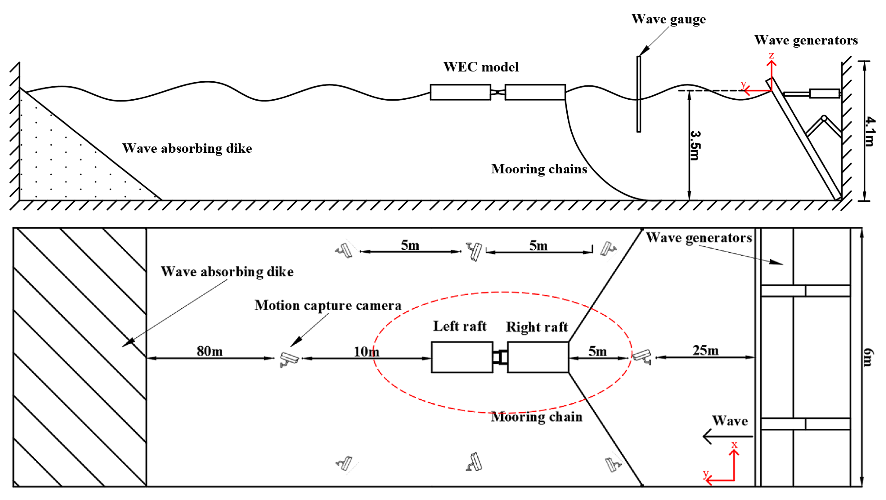
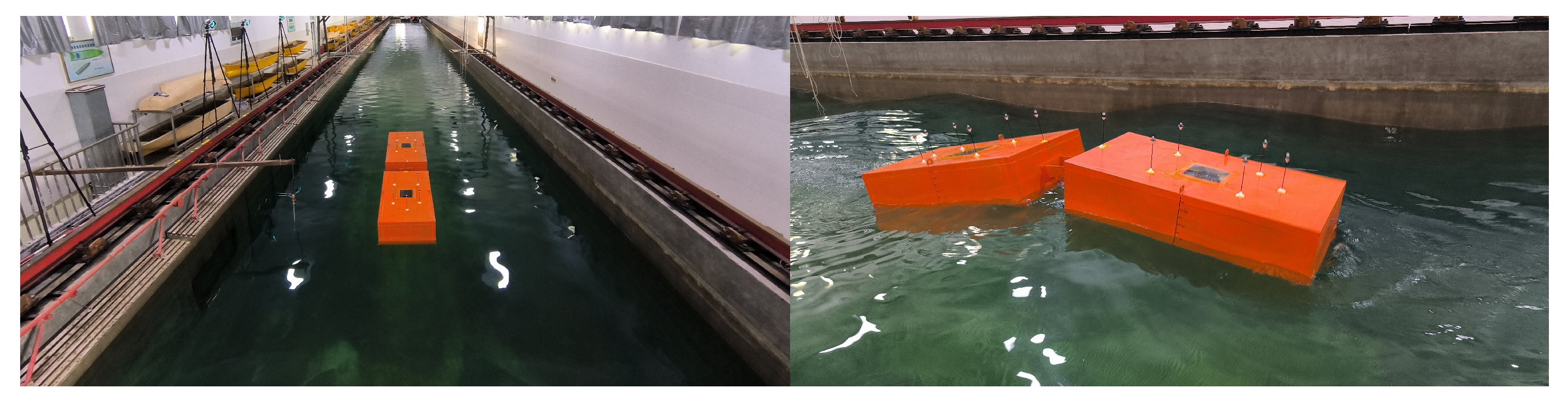
The intricate nature of a coupled raft-type WEC necessitates consideration not only of the multibody hydrodynamics but also of the dynamics inherent in its mooring and connection systems. In this context, while significant research has been conducted on raft-type WECs, there remains a need for further advancements, particularly in the realm of diverse catenary mooring configurations. This paper undertakes an assessment of a raft-type WEC’s performance under various mooring configurations and different wave conditions. The dynamics of the two-body WEC were simulated using a weakly nonlinear three-dimensional potential flow solver. The approach involved a two-step strategy. Firstly, wave forces and hydrodynamic coefficients were computed using a diffraction–radiation model in the frequency domain. Subsequently, the motion equations of the multibody system were solved in the time domain, incorporating the effects of PTO and mooring systems. This investigation incorporates the utilization of equivalent linear damping to model the PTO system. To validate the numerical simulations, physical model experiments with WECs were conducted. Furthermore, the coupled dynamics of the raft-type WEC with various mooring configurations were examined, emphasizing the differences in its performance.
This article is structured as follows: In
Section 2, the adopted numerical methodology is briefly presented.
Section 3 follows, dedicated to the physical model designed to provide validation data for the employed numerical model. The effects of power take-off (PTO) damping and mooring configurations are discussed in
Section 4, and the article concludes with remarks in
Section 5.
2. Numerical Methods
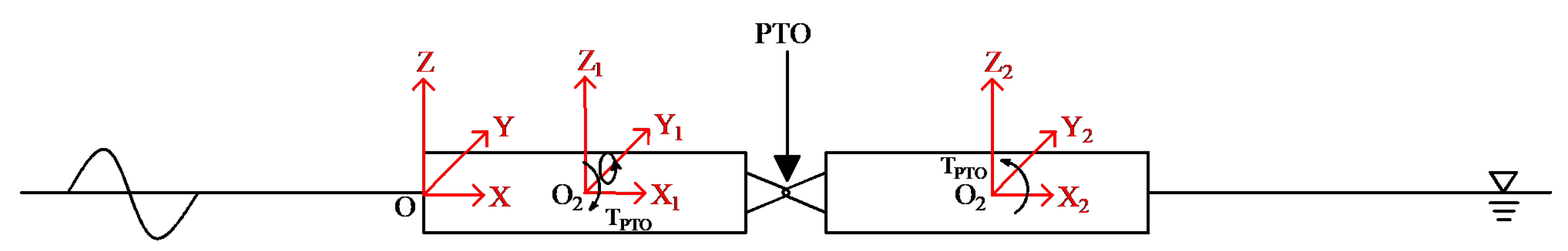
To describe the motion of two interconnected floating bodies in waves, several right-handed orthogonal coordinate systems are utilized, as illustrated in
Figure 1. The first coordinate system, denoted as
o-
, represents the global reference frame. The second coordinate system,
-
, is a local reference frame fixed to one of the bodies. The third coordinate system,
-
, is a local frame fixed to the other body. An additional local coordinate system is affixed to the PTO system. In this configuration, the global coordinate system is aligned with the undisturbed free surface. The
x-axis of the global system points in the direction of the body’s stern, while the
z-axis is oriented vertically upward.
The initial calculations of the first-order hydrodynamic responses, including with added mass and damping terms, as well as incident and diffracted wave loads, were carried out in the frequency domain using the linear potential flow solver AQWA [
33]. Subsequently, weakly nonlinear time-domain simulations were conducted, where nonlinear Froude–Krylov and hydrostatic forces were estimated under the influence of an instantaneous incident wave surface. The hydrodynamic interaction of multiple bodies was considered through three-dimensional linear diffraction and radiation analyses. Furthermore, second-order wave loads were incorporated, and these calculations were based on the complete quadratic transfer function (QTF) matrix.
2.1. Potential Flow Approach
For a flow assumed to be incompressible, inviscid, and irrotational, its velocity potential satisfies the Laplace equation everywhere in the fluid domain:
The total unsteady linear potential for a sinusoidal wave excitation with frequency
is expressed as follows:
where
denotes the incident wave potential;
represents the diffraction potential;
represents the body motions across different degrees of freedom; and
signifies the radiation potentials. The combined potential resulting from both diffraction and radiation is referred to as the scattered potential, denoted as
. The WEC has zero forward speed, and its free surface condition is satisfied:
For the diffraction potentials, the body boundary condition is satisfied:
For the radiation potentials, the body boundary condition is satisfied:
The seabed surface condition at depth
d is also satisfied:
At infinity, the generalized wave disturbance must approach zero, i.e., the radiation condition has to be satisfied:
where
denotes the distance from the oscillating body and
is the wave velocity. The hydrodynamic pressure on the two-module hull surface is calculated using Bernoulli’s equation:
where
p is the pressure,
is the water density, and
g is the acceleration of gravity. The wave-exciting force consists of the incident and diffracted part,
, and the radiated part,
. Integrating the pressure on a body’s surface obtains in the incident and diffracted parts:
The radiated part is then expressed as follows:
where
. Terms
and
are the added mass and damping coefficients, respectively:
2.2. Motion Response of a Raft-Type WEC
As the added mass
A and the hydrodynamic damping
c are frequency-dependent, the equation of motion of such a floating system is expressed in a convolution integral form in time domain calculations [
34]:
where
m and
K are the
mass and stiffness matrices, respectively.
U is the
motion response and
F is the
external force at frequency
. Furthermore, the acceleration impulse matrix is defined as:
where
and
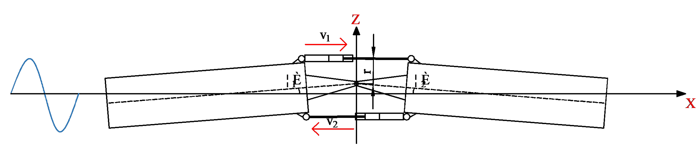
are the added mass and hydrodynamic damping matrices, respectively. The computational analysis of the captured power is performed in the coordinate system fixed in the connector, as depicted in
Figure 2.
When there is relative motion between the two floating bodies, the relative angular displacement of the neighboring floats can be defined as follows:
where
and
are the pitch angular displacements of float 1 and float 2, respectively. Furthermore, the moment at the articulation can be described as:
Here,
C in the equation signifies equivalent rotational damping. Based on the power expression, the equation for instantaneous power is obtained as:
Assuming that the relative pitch displacements of the two floating bodies under the influence of a regular wave can be expressed as:
where, in this equation,
represents the amplitude of the relative pitch angular velocity, the average power of the device during a period
T can be described as:
In terms of linear wave theory, the power of an incident wave per unit width can be expressed as:
where
H is the wave height, and the efficiency of the device utilizing wave energy can be expressed in terms of the energy capture factor, which can be written as:
where
d is the width of the floating body.
4. Numerical Results and Discussions
This section presents a comprehensive examination of the results generated using the validated numerical model. It starts by exploring the motion characteristics of the raft-type WEC in regular waves across various wave frequencies. Subsequently, the study delves into the analysis of the impacts of rotational damping, which is simplified as the linear PTO system. The section ends with a discussion on the influence of mooring configurations on the energy capture ratio of the considered WEC.
4.1. Hydrodynamic Characteristics of the Two-Body System
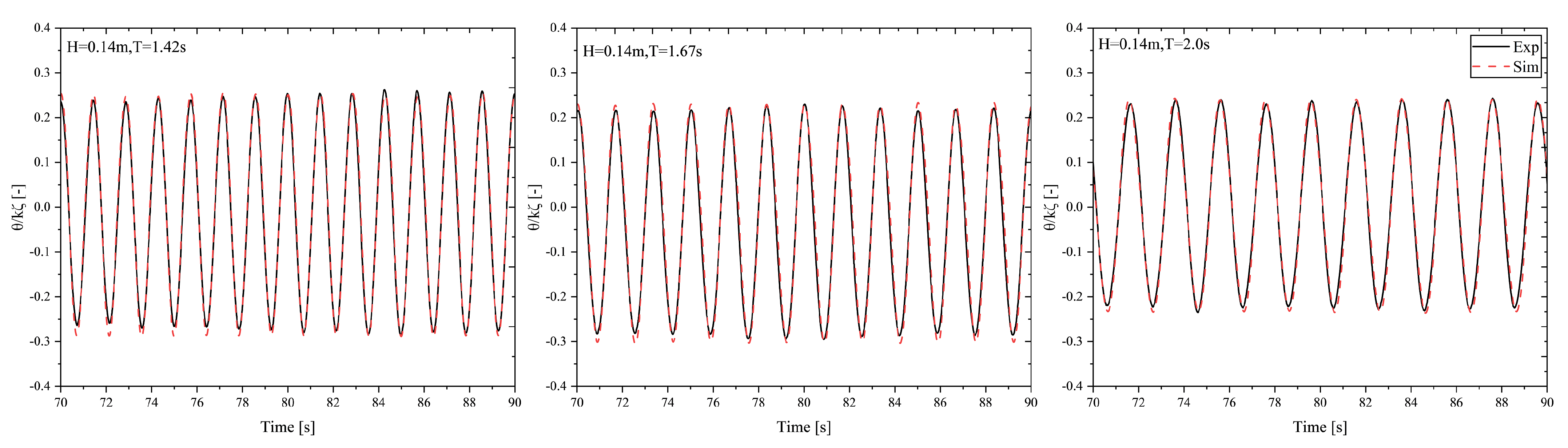
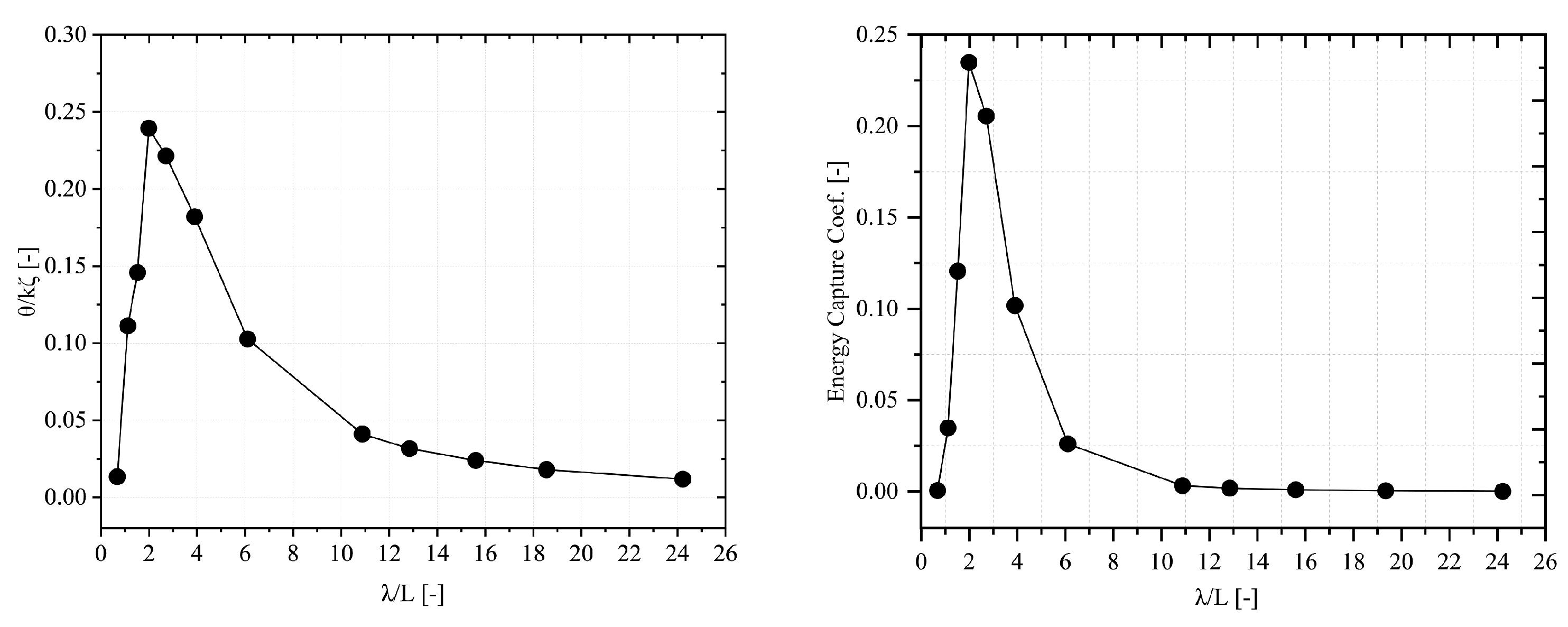
The double-float configuration comprises front and rear floating bodies, with their hydrodynamic performance significantly influencing the overall WEC performance. Therefore, their hydrodynamic characteristics were evaluated first in the time domain calculations. The wave height selected for this analysis was
m, encompassing wavelengths in the range of
, while a PTO damping of 100 Nms/rad was utilized. Second-order Stokes wave theory was adopted in our time domain calculations, and the corresponding relative pitch motions are plotted in
Figure 7. Again,
is the wavelength,
k is the wave number, and
L is the length of a single floating body.
As shown, the motion response of the WEC is associated with the wavelength. The relative pitch motion initially increases and then decreases as the wavelength increases. When is approximately 2.0, which corresponds to the length of a single float being equal to the wavelength, it results in the most pronounced relative motion between the floats. At this point, the relative pitch motion amplitude between the two bodies reaches its peak, and the energy capture efficiency is maximized. However, it is noticeable that significant deviations from this resonant condition lead to reduced amplitudes in the two bodies’ relative motion. In terms of capture efficiency, it exhibits a similar trend of an initial increase and a subsequent decrease, with a peak occurring when is approximately 2.0. However, as the wavelength increases, the energy harvesting efficiency decreases dramatically, approaching negligible values.
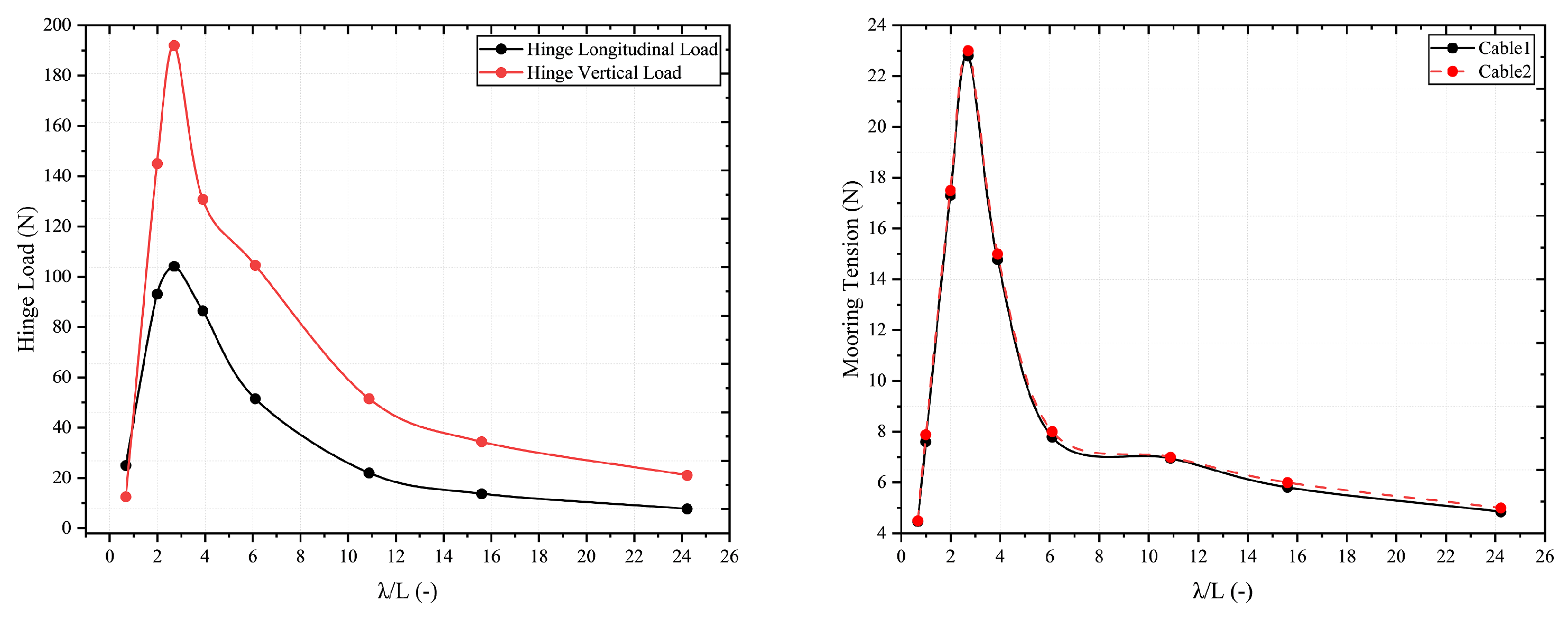
This behavior can be attributed to the fact that when the wavelength is relatively small, the WEC is distributed across several wavelengths, resulting in a homogenizing effect with a minimal relative motion amplitude. On the other hand, with a considerably larger wavelength, all floating bodies are contained within a single wavelength, resulting in minimal relative pitch displacements and, subsequently, minimal power generation. Hence, an optimal wave frequency range exists at an intermediate value where the relative pitch angular velocity is most prominent, leading to maximum power output. To optimize the dimensions of the WEC, maintaining a 2:1 ratio with respect to the typical wavelength found in the local sea area is advisable for maximizing wave energy capture. Furthermore, it is observed that the loads acting on the hinged joint of the WEC between the two floating bodies also fluctuate with the wavelength, peaking around
. It is worth noting that, except in short waves, the vertical component of the hinged force typically surpasses its horizontal component, as shown in
Figure 8. In the case of tension loads on the mooring lines, a similar pattern is noticed, where they initially increase and then decrease as the wavelength increases. The maximum values for these loads also coincide with the regions of maximum motion.
4.2. Effect of PTO Damping
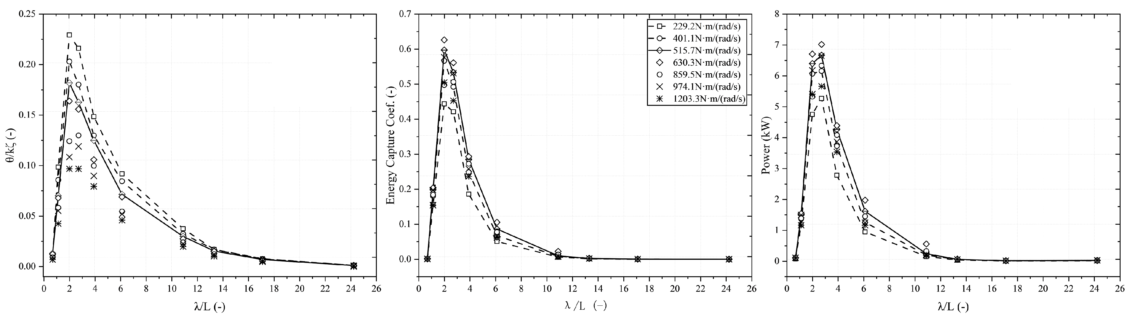
The PTO parameters play a crucial role in the power generation of the two-body articulated raft WEC. To assess the effect of damping on the captured power of the device, various parameter conditions were chosen for analysis and comparison, with the respective parameters detailed in
Figure 9.
As observed, an increase in the damping coefficients leads to a reduction in the amplitude of relative pitch motion. However, the overall trend remains unaffected by changes in damping coefficients, with their values increasing and then decreasing as the wavelength increases. On the one hand, an appropriate increase in damping is favorable for power generation. When wave energy is harnessed through the PTO system, the relative motion between the two bodes decreases as damping increases, resulting in a decrease in the captured energy power. With an initial increase in damping, the augmenting effect surpasses the diminishing effect, leading to an overall increase in captured power. However, with further increases in damping, the decreasing effect from the reduced pitch motion amplitude outweighs the increasing effect of the damping coefficient, resulting in a decrease in the energy capture coefficients. For all the damping coefficients considered in this paper, the optimal damping value is around 630.3 Nm/(rad/s), which corresponds to a maximum generated power of about 7 kW per incident wave period. It is important to note that the wave conditions for achieving the maximum energy capture coefficient do not align with the optimal wave conditions for generating the maximum power per wave period.
4.3. Effect of Mooring Configuration
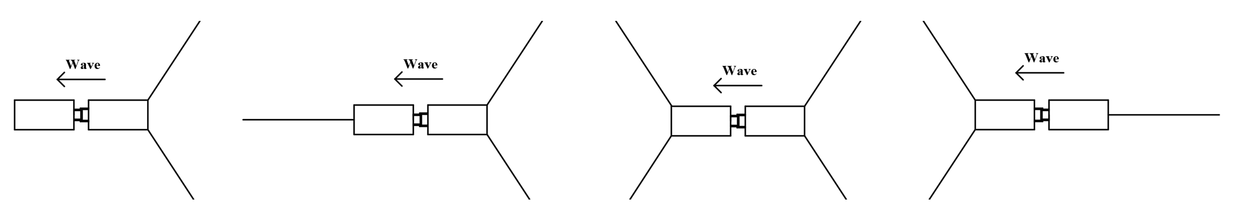
The WEC operates in inshore waters where energy capture is influenced by wave-following behavior. As the device is oriented along the wave direction and is in inshore waters, where the wave direction remains relatively stable for energy capture, a multi-point mooring system is a feasible choice. Single-point mooring, while simpler and offering a good directional stability, requires a larger operational sea area and concentrates the forces on the mooring lines, leading to higher operational and maintenance costs. Mooring ropes, as a key component of the mooring system, are commonly crafted from materials like synthetic fibers, steel cables, and anchor chains. Anchor chains are known for their excellent wear resistance but are relatively heavy. Synthetic fiber cables possess substantial horizontal restoring forces, lightweight properties, and a high stiffness. However, their axial stiffness varies with the duration of the force, making mechanical analyses complex and reducing their durability. Considering these factors, four suspension chain line mooring configurations have been developed, as illustrated in
Figure 10.
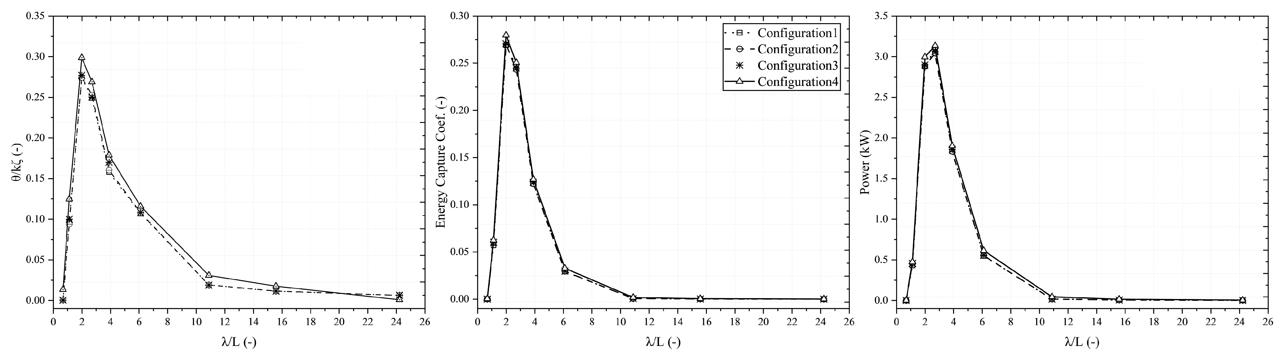
Figure 11 presents the relative pitch motions, corresponding energy capture coefficients, and the captured power for the four considered mooring configurations. The results reveal that the right-single-left-double mooring configuration slightly outperforms the other three systems. It captures more wave energy, with an approximately 0.1 kW higher peak power generation per wave period and an energy capture coefficient about 0.1 higher than the other configurations. This superior performance can be attributed to it experiencing fewer constraints from the mooring at the wave-facing end. Consequently, wave energy is transferred to the floats, promoting their movement. The right-single-left-double mooring system, with a single-point mooring at the wave-facing end, allows for a less restricted motion of the double floats. As a result, the WEC exhibits a larger pitch motion amplitude. Additionally, the wave-following nature of the raft-type WEC means that the wave direction and frequency influence the amplitude of the pitch motion. With the right-single-left-double mooring system, the mooring direction at the wave-facing end aligns with the wave’s direction, resulting in an amplification of the WEC’s pitch motion amplitude.
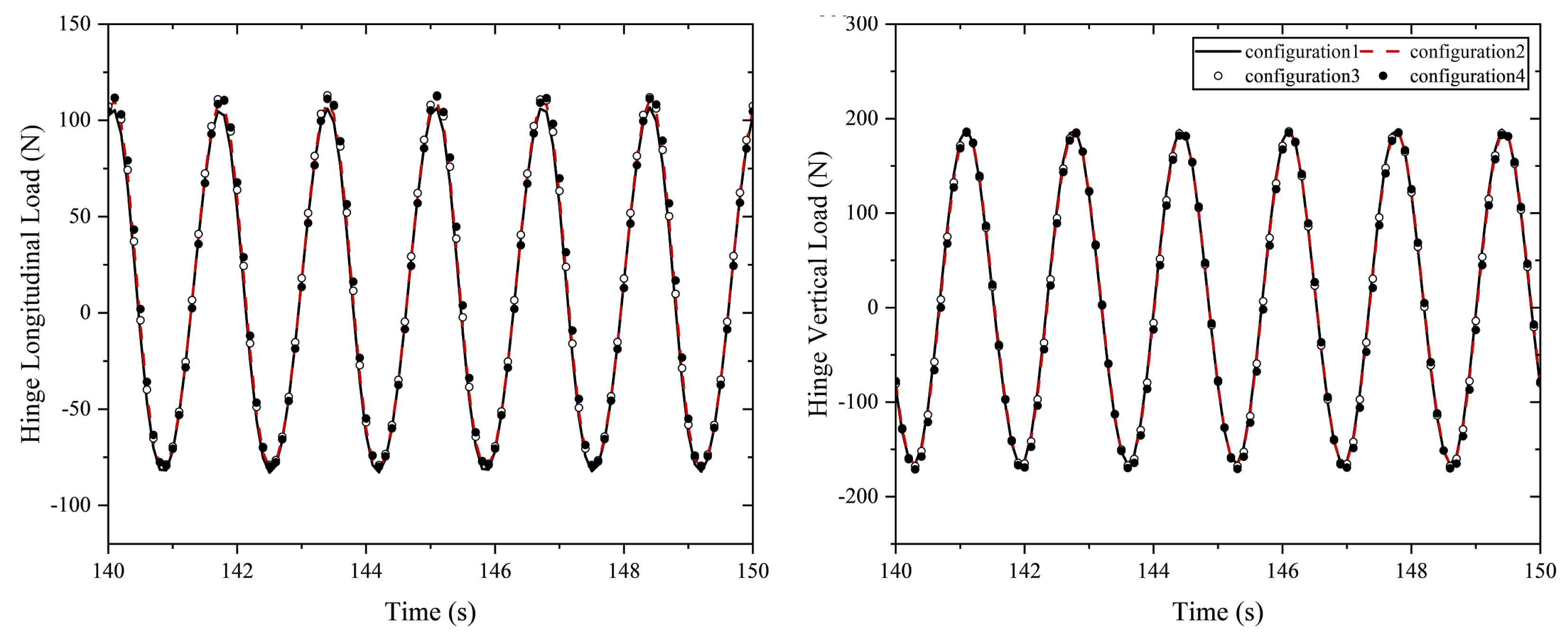
To explore the forces acting at the joint with different mooring configurations, the condition with the most pronounced pitch motion response was chosen, which corresponded to a wavelength of around
.
Figure 12 presents the horizontal and vertical loads acting on the hinged connector under various mooring configurations. It is noted that there is a gradual increase in both the longitudinal and vertical loads on the hinged connector when progressing from configuration 1 to configuration 4. Nevertheless, these increases are relatively minor, and the studied mooring configurations have minimal influence on the forces acting upon the hinged connections.
Additionally, the choice of mooring configuration significantly impacts the mooring tension.
Figure 13 illustrates the tensions in the mooring lines for the four considered configurations under the same wave conditions. Other than the low-frequency components, a consistent increase in both the mean tensions and tension amplitudes from configuration 1 to configuration 4 is observed. Notably, configuration 4 exhibits the highest mooring tension among all configurations. This disparity arises from the fact that configurations 1, 2, and 3 each employ two moorings at the wave-facing end, while configuration 4 relies on a single mooring at the wave-facing end to provide the necessary forces. In summary, although configuration 4 offers a slightly superior captive energy coefficient, it does so at the cost of a significantly higher tension in the wave-facing mooring line. Conversely, configuration 2 strikes a better balance between the energy capture efficiency and the mooring tension, all while remaining a cost-effective mooring system. In the context of inshore waters with relatively stable wave directions, configuration 2 stands out as the optimal choice.
5. Concluding Remarks
This study provides a comprehensive evaluation of the performance of a raft-type WEC under different mooring configurations and diverse wave conditions. The approach to modeling the dynamics of this two-body WEC involves a two-step strategy. Initially, wave forces and hydrodynamic coefficients in the frequency domain are calculated utilizing a diffraction–radiation model. Subsequently, the motion equations of the multibody system are solved in the time domain, accounting for the impact of PTO and mooring systems. Notably, our analysis incorporates the use of equivalent linear damping to represent the PTO system. To verify the accuracy of our numerical simulations, we conduct physical model experiments with the WECs. In addition to this, we explore the coupled dynamics of the raft-type WEC with different mooring configurations, with a specific focus on highlighting the variations in their performance.
The results reveal that the relative pitch motion of the WEC is closely associated with the wavelength. Initially, the relative pitch motion increased and then decreased as the wavelength increased. The most significant relative motion between the two floats occurred when was approximately 2.0, indicating a resonant condition. At this point, the relative pitch motion reached its peak amplitude, leading to a maximum energy capture efficiency. On the other hand, the loads acting on the hinged joint between the two floating bodies and the mooring lines were observed to fluctuate with the wavelength, peaking around . Notably, the vertical component of the hinged force typically exceeded the horizontal component for long waves. Tension loads on the mooring lines followed a similar pattern, initially increasing and then decreasing with the wavelength, with maximum values corresponding to regions of maximum motion.
The PTO parameters are a critical factor in determining the power generation of the WEC, and their impact on the device’s captured power was also assessed. It was observed that an increase in the damping coefficients led to a reduction in the amplitude of the relative pitch motion. However, the overall trend remained consistent, with the value of relative pitch motion initially increasing and then decreasing as the wavelength increased. With an initial increase in damping, the effect of augmented damping surpassed the diminishing effect, resulting in an overall increase in captured power. However, as the damping continued to increase, the diminishing effect from the reduced pitch motion amplitude outweighed the increasing effect of the damping coefficient. This led to a decrease in the energy capture coefficients. It is important to note that the wave conditions for achieving the maximum energy capture coefficient did not align with the optimal wave conditions for generating the maximum power per wave period. In terms of mooring configurations, while configuration 4 offers a slightly superior captive energy coefficient, it comes at the cost of a significantly higher tension in the wave-facing mooring line. Configuration 2, on the other hand, strikes a better balance between the energy capture efficiency and the mooring tension, all while remaining a cost-effective mooring system. This makes it the optimal choice for inshore waters with relatively stable wave directions.


