
A Novel Deformation Analytical Solution and Constitutive Model for Fractured Rock Masses


Abstract
:1. Introduction
2. Fracture Hydraulics
3. Analytical Solution of Fracture Deformation with a Single-Fracture Rock Mass Model
4. Analytical Solution of the Deformation of a Fractured Rock Mass Using a Multiple-Fracture Rock Mass Model
4.1. Constitutive Model
4.2. Verification
5. Conclusions
- (1)
- The relationship between rock deformation and the fracture flow rate was studied based on a single-fracture rock mass model. The fracture deformation calculation formula was derived from the fracture hydraulic calculation formula, and the rationality of the calculation formula was verified by comparing it with measured data.
- (2)
- Based on the calculation formula for fracture deformation, a calculation formula for rock mass deformation containing multiple sets of fracture surfaces was derived, and the stress-strain constitutive relationship of complex rock masses was established. The correctness of the calculation method in this paper was verified by comparing it with other theoretical calculation results.
Author Contributions
Funding
Informed Consent Statement
Data Availability Statement
Conflicts of Interest
Abbreviations
| g | gravitational acceleration, N/kg |
| e | fracture width, m |
| A | top of the fracture surface of rock component |
| B | bottom of the fracture surface of rock component |
| P | water pressure at the bottom of the fracture surface of the rock component, Pa |
| P0 | hydrostatic pressure of water within the fracture, Pa |
| ∆P | water head difference of the middle location to one of the ends of the fracture, Pa |
| ∆eshear | fracture deformation under pure shear condition, m |
| ∆ec−s | fracture deformation with pure transpression condition, m |
| e0 | initial fracture width, m |
| ∆e | fracture deformation, also the variation of the fracture width, m |
| γ | coefficient of viscosity of the water, m2/s |
| J | hydraulic gradient |
| β | connected parameter |
| c | modified parameter of the relative roughness for the fracture surface |
| ∆ | convex degree of the fracture surface, m |
| kf | permeability parameter of the fracture, m/s |
| Q | flow rate, m3/s |
| q | flow rate in a fracture within unit length, m2/s |
| V | flow velocity, m/s |
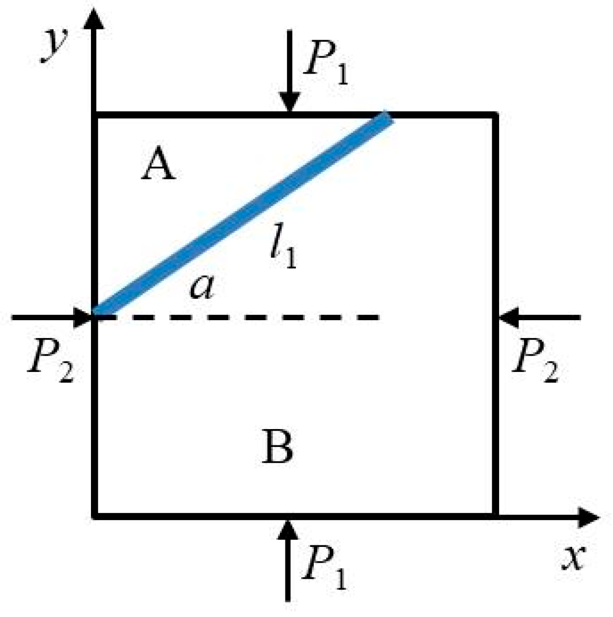
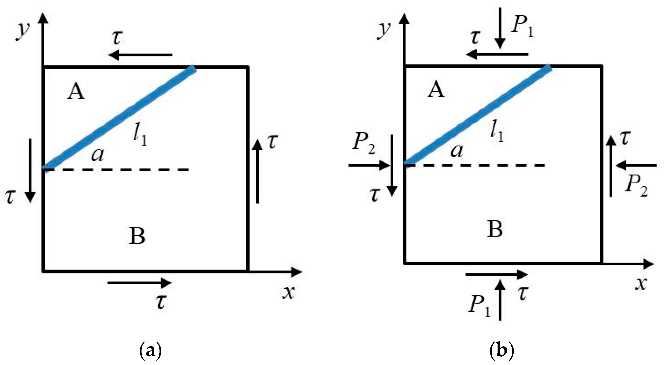
| l1 | fracture length, m |
| α | horizontal angle, ° |
| P1 | vertical pressure, Pa |
| P2 | horizontal pressure, Pa |
| n | porosity of the filler substance, n = 1 represents no filler substance. |
| J0 | head pressure per unit, Pa |
| τ | effective shear stress on the rock mass, Pa |
| kn | normal stiffness of the fracture, Pa/m |
| ks | tangential stiffness, Pa/m |
| Lx | width of the rock mass within a representative zone, m |
| Ly | height of the rock mass within a representative zone, m |
| E0 | elastic modulus of rock, Pa |
| ν | Poisson’s ratio for the rock |
| Nr | normal direction of the rth fracture |
| Δui | equivalent deformation of any fracture, m |
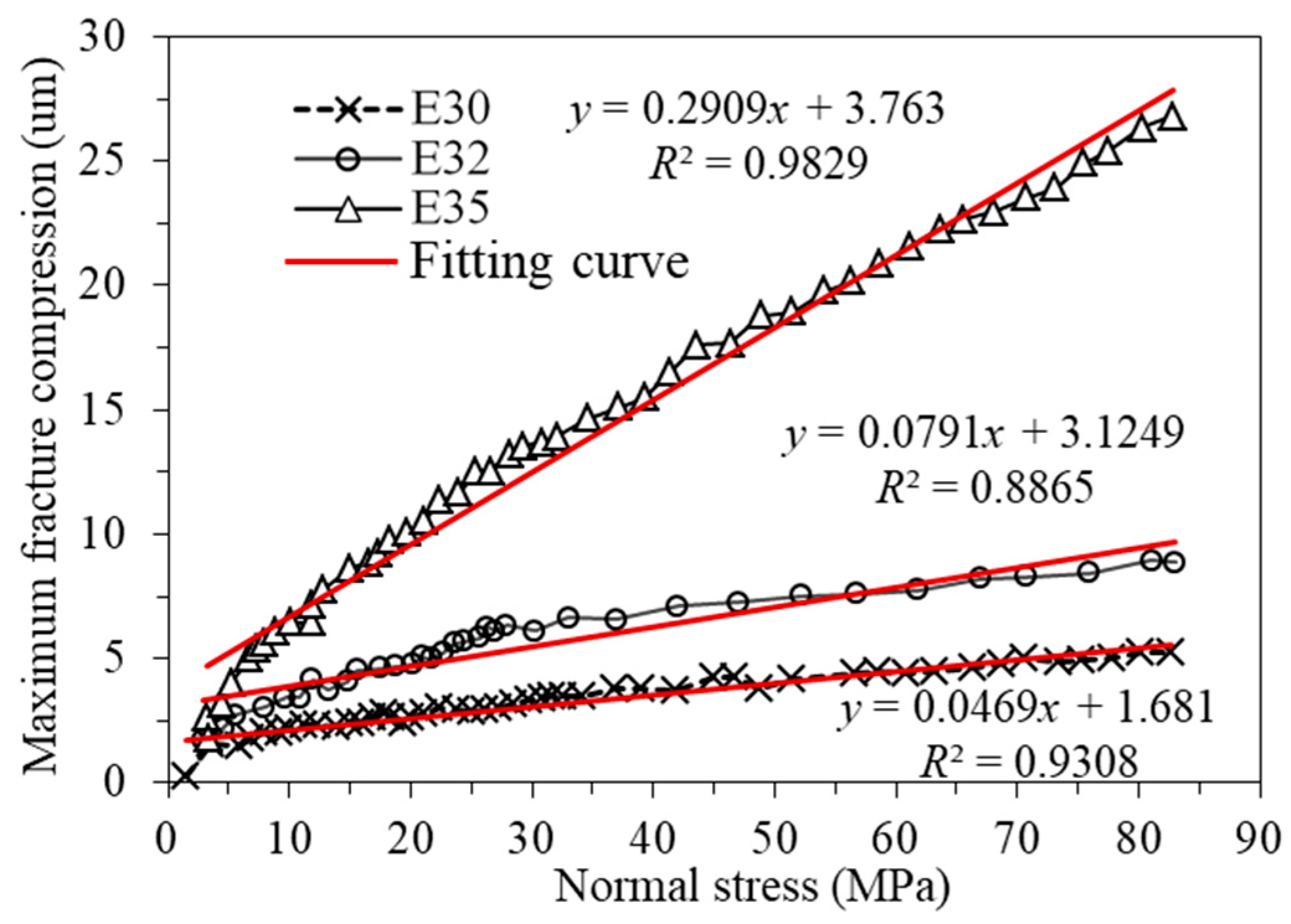
| emax | maximum fracture compression, m |
| E | equivalent deformation modulus of rock mass, Pa |
| s | length of the fracture, m |
| εij | strain tensor in terms of components in an orthonormal frame |
| σij | stress tensor in terms of components in an orthonormal frame, Pa |
| δij | identity tensor in terms of components in an orthonormal frame |
| σkk | trace of stress tensor, Pa |
| εxxc | normal strain in the direction of x |
| εyyc | normal strain in the direction of y |
| εxyc, εyxc | shear strain caused by the fracture deformation. |
| εijc | strain tensor caused by the fracture deformation in terms of components in an orthonormal frame. |
References
- Zhang, T.; Xu, W.Y.; Wang, H.L.; Wang, R.B.; Yan, L.; Hu, M.T. Anisotropic mechanical behaviour of columnar jointed rock masses subjected to cyclic loading: An experimental investigation. Int. J. Rock Mech. Min. Sci. 2021, 148, 104954. [Google Scholar] [CrossRef]
- Hossaini, K.A.; Babanouri, N.; Nasab, S.K. The influence of asperity deformability on the mechanical behavior of rock joints. Int. J. Rock Mech. Min. Sci. 2014, 70, 154–161. [Google Scholar] [CrossRef]
- Prudencio, M.; Jan, M. Strength and failure modes of rock mass models with non-persistent joints. Int. J. Rock Mech. Min. Sci. 2007, 44, 890–902. [Google Scholar] [CrossRef]
- Zhang, J.; Kikumoto, M.; Yasuhara, H.; Ogata, S.; Kishida, K. Modeling the shearing behavior of discontinuous rock mass incorporating dilation of joint aperture. Int. J. Rock Mech. Min. Sci. 2022, 153, 105101. [Google Scholar] [CrossRef]
- Rehman, H.; Ali, W.; Naji, A. Review of rock-mass rating and tunneling quality index systems for tunnel design: Development, refinement, application and limitation. Appl. Sci. 2018, 8, 1250. [Google Scholar] [CrossRef]
- Cai, M.; Kaiser, P.K.; Tasaka, Y.; Minami, M. Determination of residual strength parameters of jointed rock masses using the GSI system. Int. J. Rock Mech. Min. Sci. 2007, 44, 247–265. [Google Scholar] [CrossRef]
- Sitharam, T.G.; Sridevi, J.; Shimizu, N. Practical equivalent continuum characterization of jointed rock masses. Int. J. Rock Mech. Min. Sci. 2001, 38, 437–448. [Google Scholar] [CrossRef]
- Potyondy, D.O.; Cundall, P.A. A bonded-particle model for rock. Int. J. Rock Mech. Min. Sci. 2004, 41, 1329–1364. [Google Scholar] [CrossRef]
- Shi, G.H.; Goodman, R.E. Discontinuous Deformation Analysis. In Proceedings of the 25th U.S. Symposium on Rock Mechanics, Evanston, IL, USA, 25–27 June 1984; pp. 269–277. [Google Scholar]
- Cui, L.; Yang, W.Y.; Zheng, J.J.; Sheng, Q. Improved equations of ground pressure for shallow large-diameter shield tunnel considering multiple impact factors. Tunn. Undergr. Space Technol. 2023, 138, 105166. [Google Scholar] [CrossRef]
- Latha, G.M.; Garaga, A. Elasto-plastic analysis of jointed rocks using discrete continuum and equivalent continuum approaches. Int. J. Rock Mech. Min. Sci. 2012, 53, 56–63. [Google Scholar] [CrossRef]
- Meng, Q.X.; Wang, H.L.; Xu, W.Y.; Chen, Y.L. Numerical homogenization study on the effects of columnar jointed structure on the mechanical properties of rock mass. Int. J. Rock Mech. Min. Sci. 2019, 124, 104127. [Google Scholar] [CrossRef]
- Chang, L.M.; Alejano, R.L.; Cui, L.; Sheng, Q.; Xie, M.X. Limitation of convergence-confinement method on three-dimensional tunnelling effect. Sci. Rep. 2023, 13, 1988. [Google Scholar] [CrossRef] [PubMed]
- Fossum, A.; Effective, F. Elastic properties for a randomly jointed rock mass. Int. J. Rock Mech. Min. Sci. Geomech. Abstr. 1985, 22, 467–470. [Google Scholar] [CrossRef]
- Wang, T.T.; Huang, T.H. A constitutive model for the deformation of a rock mass containing sets of ubiquitous joints. Int. J. Rock Mech. Min. Sci. 2009, 46, 521–530. [Google Scholar] [CrossRef]
- Amadei, B.; Goodman, R.E. A 3-D constitutive relation for fractured rock masses. Proceedings of the International Symposium on the Mechanical Behavior of Structure Media. Ottawa 1981, 5, 249–268. [Google Scholar]
- Yang, J.P.; Chen, W.Z.; Yang, D.S.; Yang, D.S.; Tian, H.M. Estimation of Elastic Moduli of Non-persistent Fractured Rock Masses. Rock Mech. Rock Eng. 2016, 49, 1977–1983. [Google Scholar] [CrossRef]
- Han, J.; Li, S.C.; Li, S.C.; Tong, X.H.; Li, W.T. Study of deformation characteristic of rock mass with Multiple persistent crack sets. Chin. J. Rock Mech. Eng. 2011, 30, 3319–3325. [Google Scholar]
- Cui, L.; Zheng, J.J.; Zhang, R.J.; Dong, Y.K. Elasto-plastic analysis of a circular opening in rock mass with confining stress-dependent strain-softening behaviour. Tunn. Undergr. Space Technol. 2015, 50, 94–108. [Google Scholar] [CrossRef]
- Zhang, Y.T. Rock Hydraulics and Engineering; China Water Resources and Hydropower Press: Beijing, China, 2005. [Google Scholar]
- Dong, Y.K.; Wang, D.; Randolph, M. Quantification of impact forces on fixed mudmats from submarine landslides using the material point method. Appl. Ocean Res. 2020, 146, 21–28. [Google Scholar] [CrossRef]
- Louis, C. Rock Hydraulic in Rock Mechanics; Springer: New York, NY, USA, 1974. [Google Scholar]
- Nolte, D.D.; Pyrak-Nolte, L.J.; Cook, N.G.W. The fractal geometry of flow paths in natural fractures in rock and the approach to percolation. Fractals Geophys. 1989, 64, 111–138. [Google Scholar]
- Esaki, T.; Hojo, H.; Kimora, T.; Kameda, N. Shear-flow coupling test on rock joints. In Proceedings of the 7th International Congress ISRM, Aachen, Germany, 16–20 September 1991; pp. 389–392. [Google Scholar]
- Detournay, E. Hydraulic conductivity of closed rock fracture: An experimental and analytical study. In Underground Rock Engineering, Proceedings of the 13th Canadian Rock Mechanics Symposium, Toronto, ON, Canada, 28–29 May 1980; CIMM: Montreal, QC, Canada, 1980; Volume 22, pp. 168–173. [Google Scholar]
- Elsworth, D. A model to evaluate the transient hydraulic response of three-dimensional sparsely fractured rock masses. Water Resour. Res. 2010, 22, 1809–1819. [Google Scholar] [CrossRef]

| Fracture Rock Samples | Normal Stiffness of Fracture: kn (MPa/m) | Maximum Fracture Compression: emax (μm) |
|---|---|---|
| E30 | 7 × 10⁶ | 12.5 |
| E32 | 15 × 106 | 6.6 |
| E35 | 3 × 10⁶ | 46.0 |
| Fracture Rock Samples | Modified Parameter of the Relative Roughness c | Convex Degree Δ (μm) |
|---|---|---|
| E30 | 73.44 | 50.96 |
| E32 | 18.70 | 10.52 |
| E35 | 989.3 | 1070.8 |
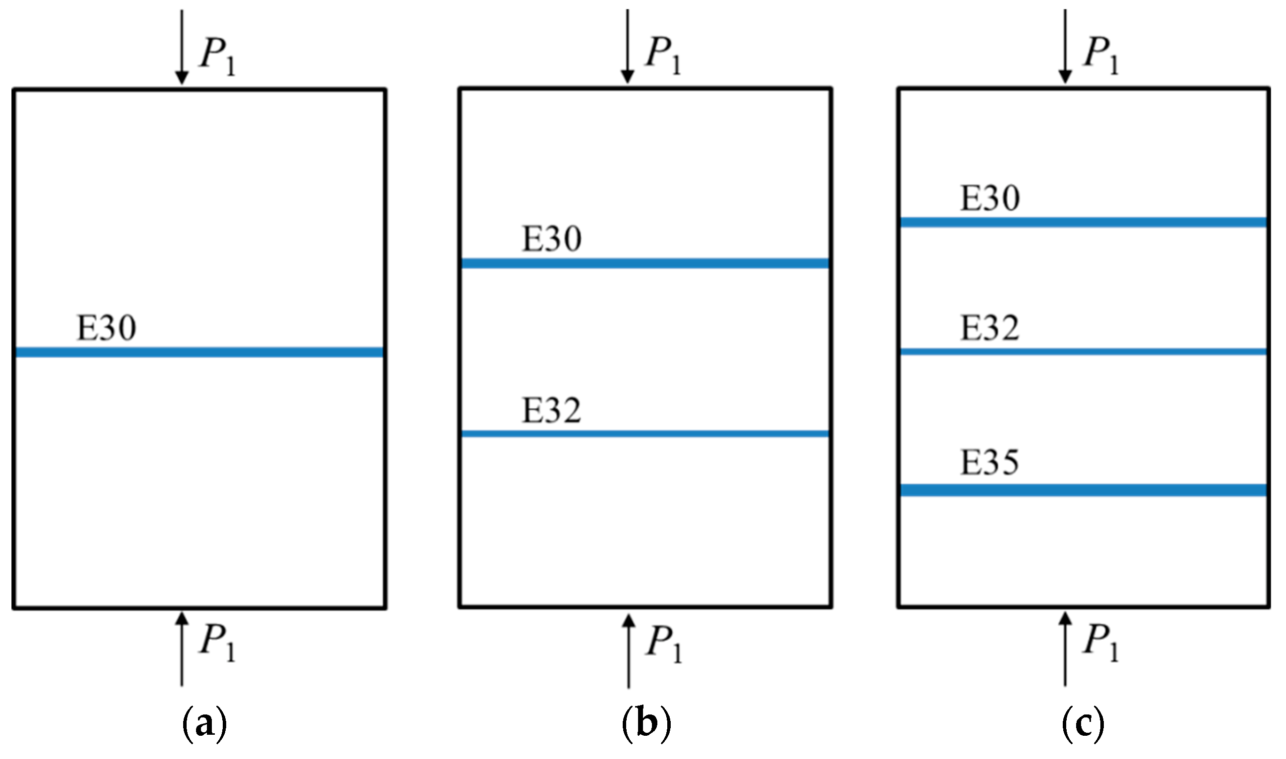
| Normal Stress (MPa) | Different Solutions | Rock Mass Deformation and Fracture Deformation (10−6 m) | ||
|---|---|---|---|---|
| One Single Fractures (a) | Two Fractures (b) | Three Fractures (c) | ||
| 20 | Proposed solution | 27.23 (1.56) | 28.14 (2.47) | 33.92 (8.25) |
| Goodman’s solution | 27.71 (2.04) | 28.66 (2.99) | 33.42 (7.76) | |
| 40 | Proposed solution | 54.46 (3.13) | 56.27 (4.94) | 67.84 (16.51) |
| Goodman’s solution | 55.42 (4.08) | 57.32 (5.99) | 66.84 (15.51) | |
| 80 | Proposed solution | 108.92 (6.26) | 112.54 (9.87) | 135.68 (33.02) |
| Goodman’s solution | 110.83 (8.16) | 114.64 (11.97) | 133.69 (31.92) | |
Disclaimer/Publisher’s Note: The statements, opinions and data contained in all publications are solely those of the individual author(s) and contributor(s) and not of MDPI and/or the editor(s). MDPI and/or the editor(s) disclaim responsibility for any injury to people or property resulting from any ideas, methods, instructions or products referred to in the content. |
© 2023 by the authors. Licensee MDPI, Basel, Switzerland. This article is an open access article distributed under the terms and conditions of the Creative Commons Attribution (CC BY) license (https://creativecommons.org/licenses/by/4.0/).
Share and Cite
Zhu, Z.; Cui, L.; Dong, Y.; Sheng, Q.; Tian, K.; Guo, Z. A Novel Deformation Analytical Solution and Constitutive Model for Fractured Rock Masses. J. Mar. Sci. Eng. 2023, 11, 2351. https://doi.org/10.3390/jmse11122351
Zhu Z, Cui L, Dong Y, Sheng Q, Tian K, Guo Z. A Novel Deformation Analytical Solution and Constitutive Model for Fractured Rock Masses. Journal of Marine Science and Engineering. 2023; 11(12):2351. https://doi.org/10.3390/jmse11122351
Chicago/Turabian StyleZhu, Zeqi, Lan Cui, Youkou Dong, Qian Sheng, Kaiwei Tian, and Zhenshan Guo. 2023. "A Novel Deformation Analytical Solution and Constitutive Model for Fractured Rock Masses" Journal of Marine Science and Engineering 11, no. 12: 2351. https://doi.org/10.3390/jmse11122351
APA StyleZhu, Z., Cui, L., Dong, Y., Sheng, Q., Tian, K., & Guo, Z. (2023). A Novel Deformation Analytical Solution and Constitutive Model for Fractured Rock Masses. Journal of Marine Science and Engineering, 11(12), 2351. https://doi.org/10.3390/jmse11122351