

A Novel Composite Pitch Control Scheme for Floating Offshore Wind Turbines with Actuator Fault Consideration

Abstract
:1. Introduction
2. FOWT Modeling
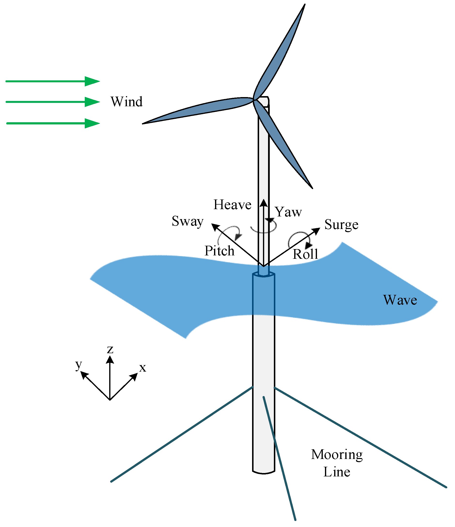
2.1. The Studied Spar-Type FOWT
2.2. Dynamics Modeling
2.2.1. Aerodynamic Model
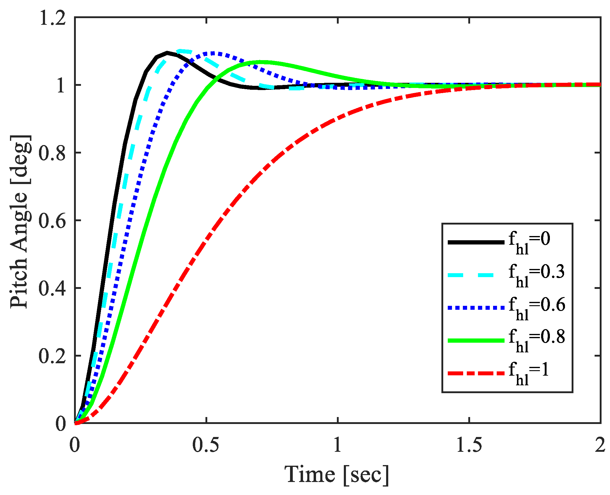
2.2.2. Pitch Actuator System and Its Fault
2.2.3. Drivetrain Model
2.2.4. Generator Model
2.3. Reduced-Order Model of the FOWT
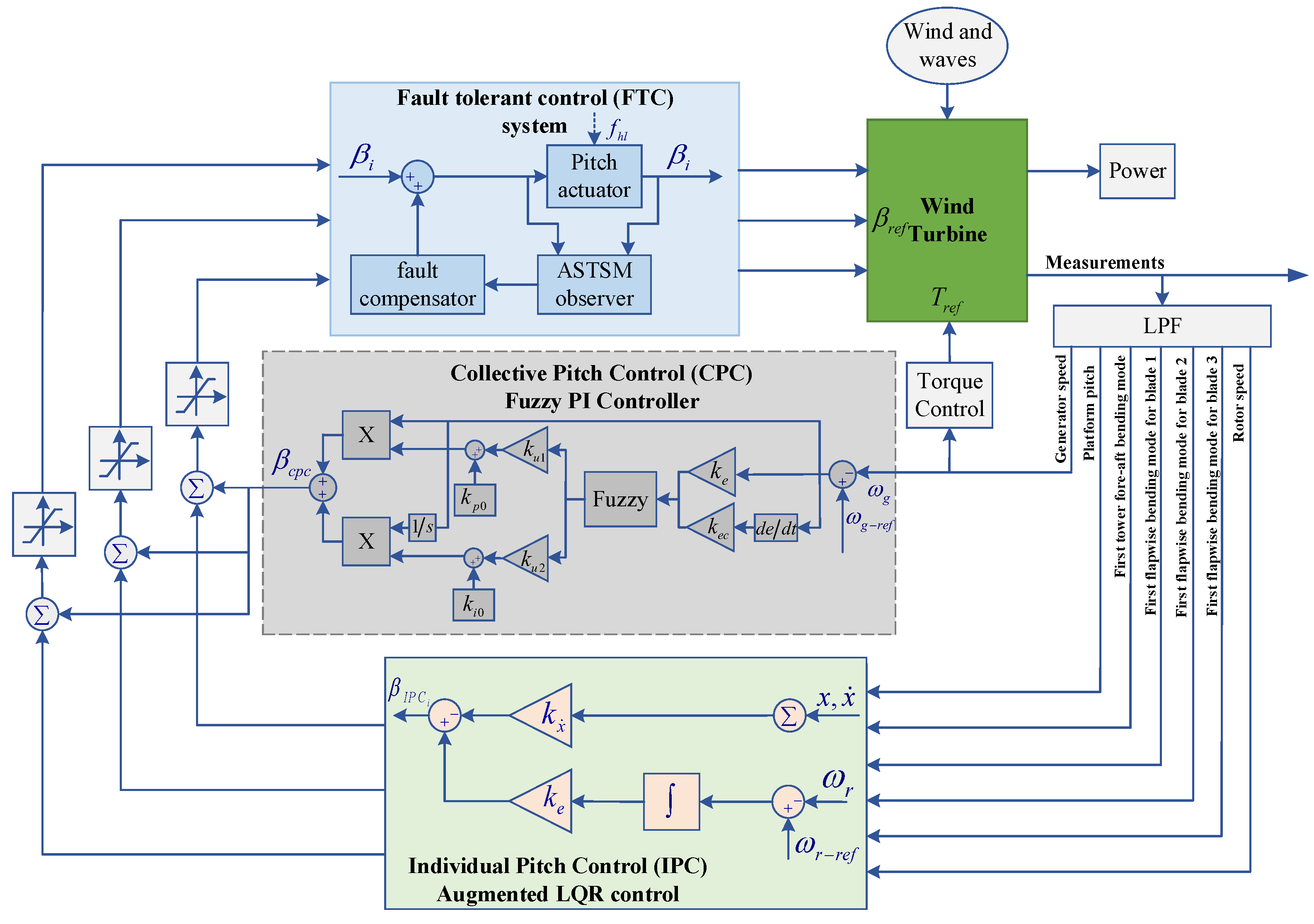
3. Research Methodology
3.1. CPC Design
3.2. IPC Design
3.2.1. Augmented LQR Controller Design
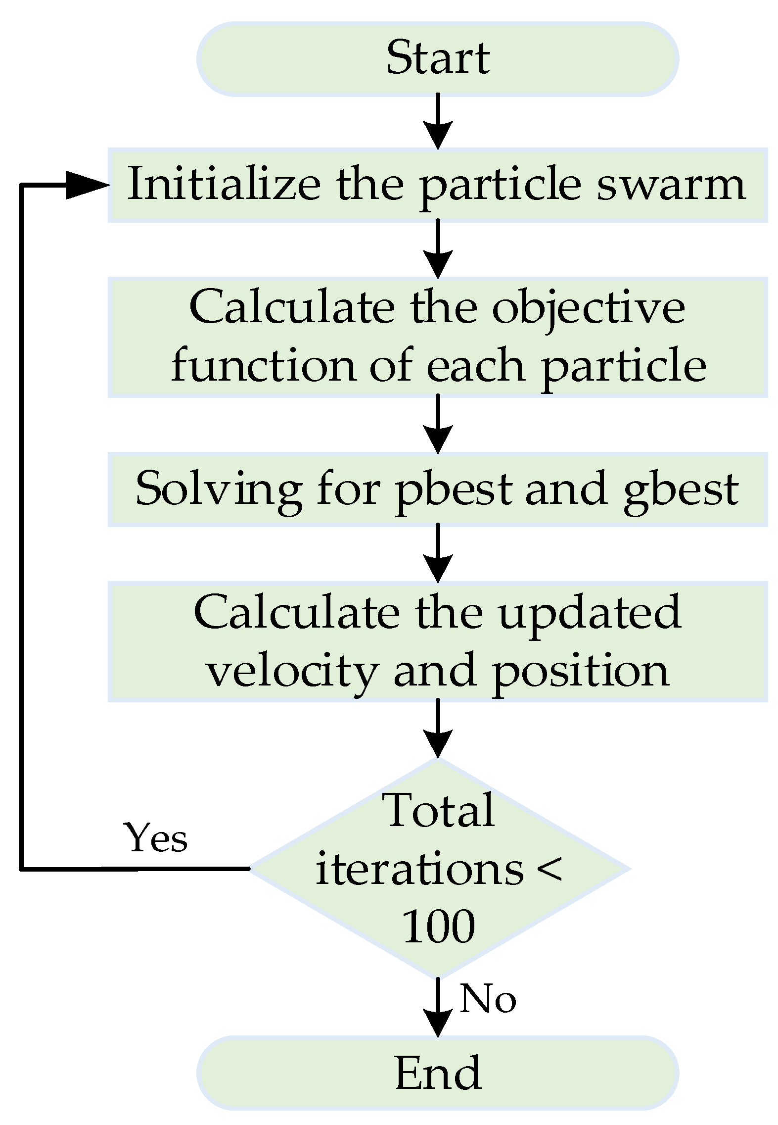
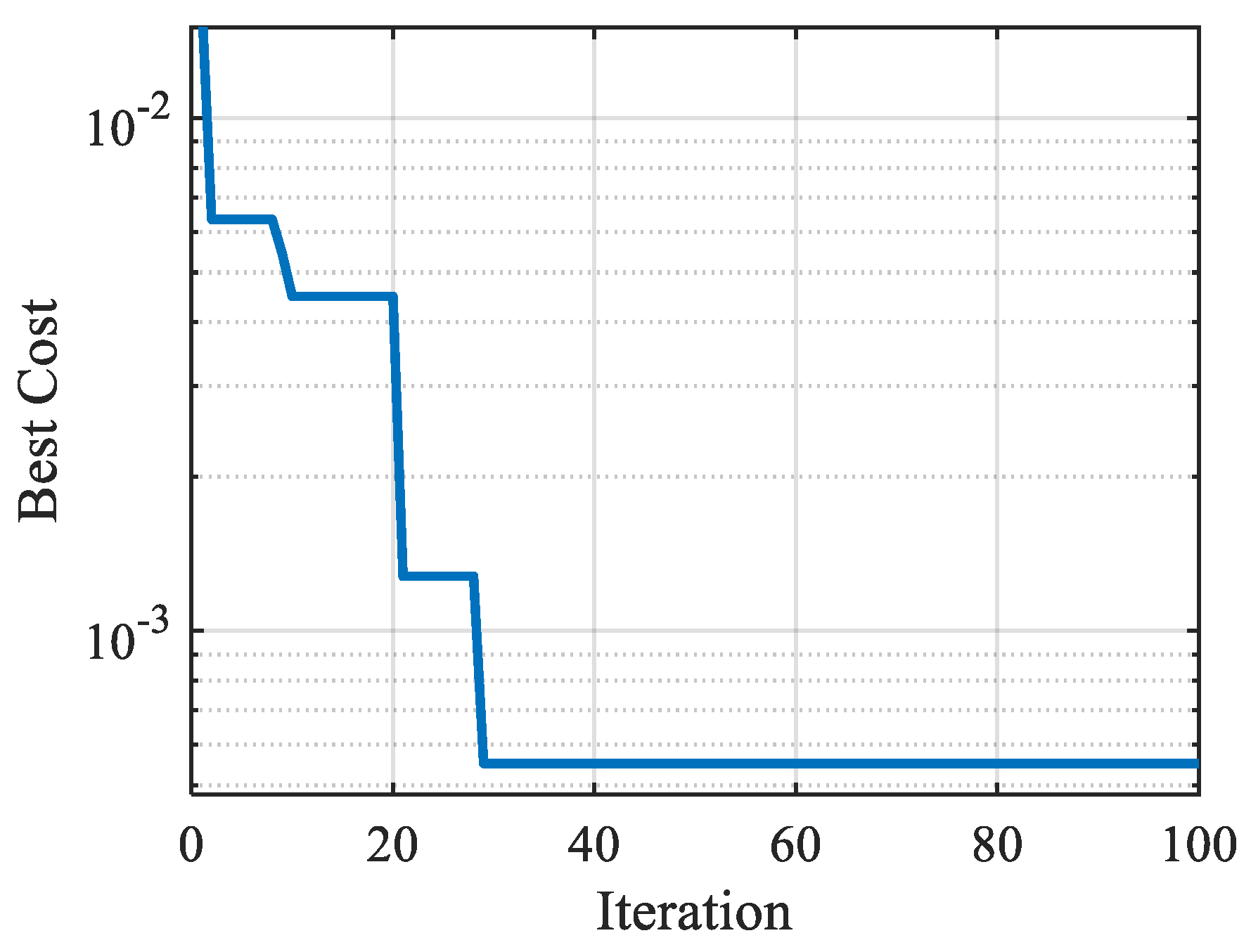
3.2.2. PSO Algorithm
3.3. ASTSM Observer Design
3.3.1. Fault Compensator
3.3.2. The ASTSM Observer
4. Simulation Results and Discussion
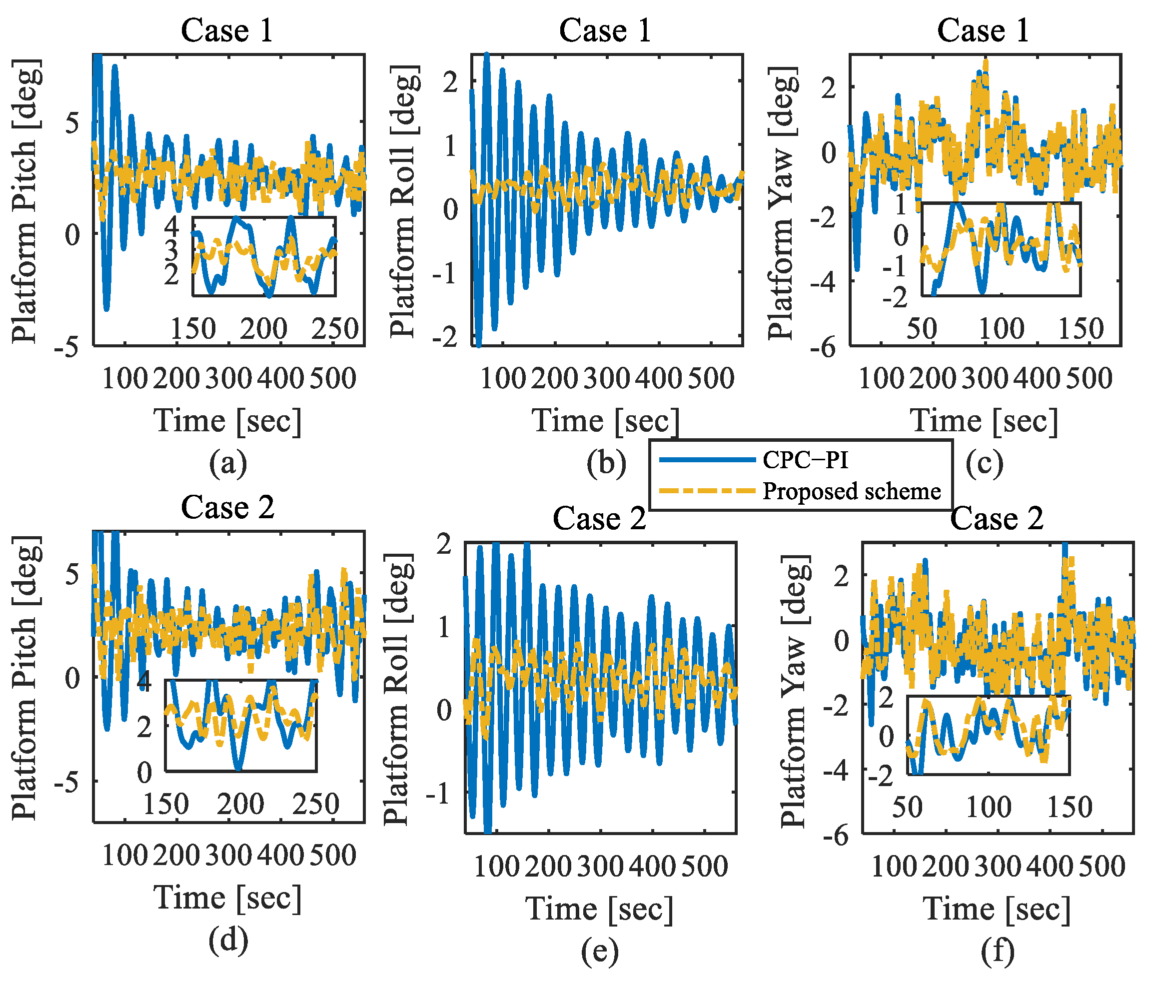
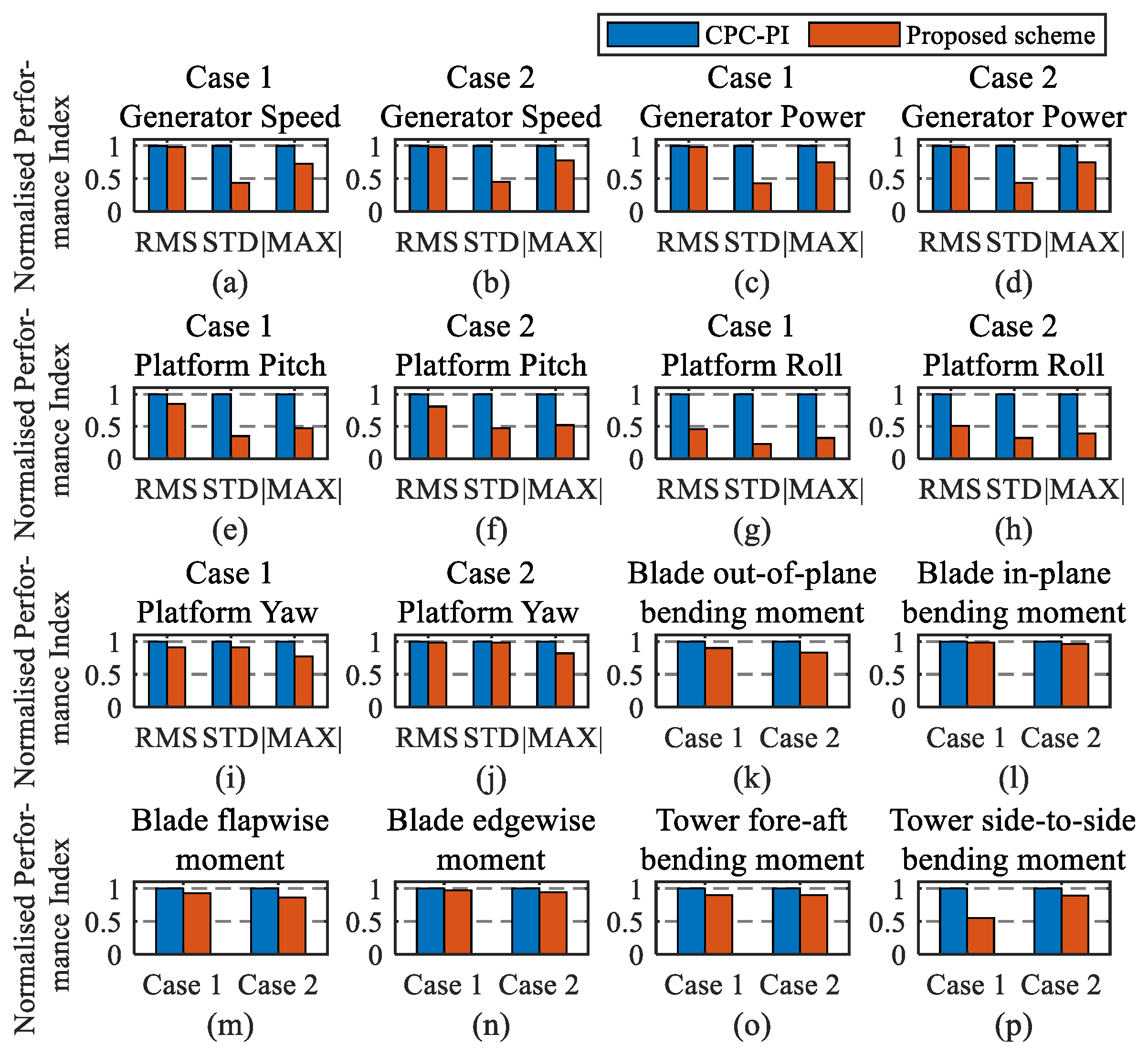
4.1. Control Performance Analysis
4.2. Performance in the Presence of Actuator Fault
5. Conclusions
Author Contributions
Funding
Institutional Review Board Statement
Informed Consent Statement
Data Availability Statement
Conflicts of Interest
References
- Ha, K.; Truong, H.V.A.; Dang, T.D.; Ahn, K.K. Recent Control Technologies for Floating Offshore Wind Energy System: A Review. Int. J. Precis. Eng. Manuf.-Green Tech. 2021, 8, 281–301. [Google Scholar] [CrossRef]
- Gambier, A.; Nazaruddin, Y.Y. Collective pitch control with active tower damping of a wind turbine by using a nonlinear PID approach. IFAC-Pap. 2018, 51, 238–243. [Google Scholar] [CrossRef]
- Lasheen, A.; Elnaggar, M.; Yassin, H. Adaptive control design and implementation for collective pitch in wind energy conversion systems. ISA Trans. 2020, 102, 251–263. [Google Scholar] [CrossRef]
- Li, S.; Han, Y.; Pan, W.; Liu, S.; Hou, M. Variable-Gain Higher-Order Sliding Mode Pitch Control of Floating Offshore Wind Turbine. J. Mar. Sci. Eng. 2021, 9, 1172. [Google Scholar] [CrossRef]
- Jongerius, S.R.; Lentink, D. Structural analysis of a dragonfly wing. Exp. Mech. 2010, 50, 1323–1334. [Google Scholar] [CrossRef]
- da Cunha Barroso Ramos, R.L. Effect of turbulence intensity on the linear quadratic control of spar buoy floating wind turbines. Mar. Syst. Ocean. Technol. 2021, 16, 84–98. [Google Scholar] [CrossRef]
- Collet, D.; Alamir, M.; Di Domenico, D.; Sabiron, G. Data-driven fatigue-oriented MPC applied to wind turbines Individual Pitch Control. Renew. Energy 2021, 170, 1008–1019. [Google Scholar] [CrossRef]
- Sarkar, S.; Fitzgerald, B.; Basu, B. Individual Blade Pitch Control Strategies for Spar-Type Floating Offshore Wind Turbines. Ph.D. Thesis, Trinity College Dublin, Dublin, Ireland, 2020. [Google Scholar]
- Bossanyi, E.A. Individual blade pitch control for load reduction. Wind. Energy Int. J. Prog. Appl. Wind. Power Convers. Technol. 2003, 6, 119–128. [Google Scholar] [CrossRef]
- Roh, C.; Ha, Y.J.; Ahn, H.J.; Kim, K.H. A Comparative Analysis of the Characteristics of Platform Motion of a Floating Offshore Wind Turbine Based on Pitch Controllers. Energies 2022, 15, 716. [Google Scholar] [CrossRef]
- Pustina, L.; Lugni, C.; Bernardini, G.; Serafini, J.; Gennaretti, M. Control of power generated by a floating offshore wind turbine perturbed by sea waves. Renew. Sustain. Energy Rev. 2020, 132, 109984. [Google Scholar] [CrossRef]
- Raach, S.; Schlipf, D.; Sandner, F.; Matha, D.; Cheng, P.W. Nonlinear model predictive control of floating wind turbines with individual pitch control. In Proceedings of the 2014 American Control Conference, Portland, OR, USA, 4–6 June 2014; IEEE: Stuttgart, Germany; pp. 4434–4439. [Google Scholar]
- Tong, X.; Zhao, X. Vibration and power regulation control of a floating wind turbine with hydrostatic transmission. Renew. Energy 2021, 167, 899–906. [Google Scholar] [CrossRef]
- Ma, Y.; Sclavounos, P.D.; Cross-Whiter, J.; Arora, D. Wave forecast and its application to the optimal control of offshore floating wind turbine for load mitigation. Renew. Energy 2018, 128, 163–176. [Google Scholar] [CrossRef]
- Namik, H.; Stol, K. Individual blade pitch control of floating offshore wind turbines. Wind. Energy Int. J. Prog. Appl. Wind. Power Convers. Technol. 2010, 13, 74–85. [Google Scholar] [CrossRef]
- Wang, L.; Ni, H.; Zhou, W.; Pardalos, P.M.; Fang, J.; Fei, M. MBPOA-based LQR controller and its application to the double-parallel inverted pendulum system. Eng. Appl. Artif. Intell. 2014, 36, 262–268. [Google Scholar] [CrossRef]
- Joelianto, E.; Christian, D.; Samsi, A. Swarm control of an unmanned quadrotor model with LQR weighting matrix optimization using genetic algorithm. J. Mechatron. Electr. Power Veh. Technol. 2020, 11, 1–10. [Google Scholar] [CrossRef]
- Al-Khazraji, H.; Rasheed, L.T. Performance Evaluation of Pole Placement and Linear Quadratic Regulator Strategies Designed for Mass-Spring-Damper System Based on Simulated Annealing and Ant Colony Optimization. J. Eng. 2021, 27, 15–31. [Google Scholar] [CrossRef]
- Murari, A.L.L.F.; Rodrigues, L.L.; Altuna, J.A.T.; Potts, A.S.; Almeida, L.A.L.; Sguarezi Filho, A.J. A LQRI power control for DFIG tuned by a weighted-PSO. Control. Eng. Pract. 2019, 85, 41–49. [Google Scholar] [CrossRef]
- Namik, H.; Stol, K. Individual blade pitch control of a spar-buoy floating wind turbine. IEEE Trans. Control. Syst. Technol. 2013, 22, 214–223. [Google Scholar] [CrossRef]
- Kim, K.; Kim, H.G.; Song, Y.; Paek, I. Design and simulation of an LQR-PI control algorithm for medium wind turbine. Energies 2019, 12, 2248. [Google Scholar] [CrossRef]
- Sarkar, S.; Chen, L.; Fitzgerald, B.; Basu, B. Multi-resolution wavelet pitch controller for spar-type floating offshore wind turbines including wave-current interactions. J. Sound Vib. 2020, 470, 115170. [Google Scholar] [CrossRef]
- Sarkar, S.; Fitzgerald, B.; Basu, B. Individual blade pitch control of floating offshore wind turbines for load mitigation and power regulation. IEEE Trans. Control. Syst. Technol. 2020, 29, 305–315. [Google Scholar] [CrossRef]
- Gao, Z.; Liu, X. An overview on fault diagnosis, prognosis and resilient control for wind turbine systems. Processes 2021, 9, 300. [Google Scholar] [CrossRef]
- Shi, F.; Patton, R.J. A robust adaptive approach to wind turbine pitch actuator component fault estimation. In Proceedings of the 2014 UKACC International Conference on Control (CONTROL), Loughborough, UK, 9–11 July 2014; IEEE: Hull, UK; pp. 468–473. [Google Scholar]
- Sun, X.; Patton, R.J. Robust actuator multiplicative fault estimation with unknown input decoupling for a wind turbine system. In Proceedings of the 2013 Conference on Control and Fault-Tolerant Systems (SysTol), Nice, France, 9–11 October 2013; IEEE: Hull, UK; pp. 263–268. [Google Scholar]
- Bai, H.; Yu, B.; Gu, W. Research on Position Sensorless Control of RDT Motor Based on Improved SMO with Continuous Hyperbolic Tangent Function and Improved Feedforward PLL. J. Mar. Sci. Eng. 2023, 11, 642. [Google Scholar] [CrossRef]
- Georg, S.; Schulte, H. Diagnosis of actuator parameter faults in wind turbines using a takagi-sugeno sliding mode observer. In Intelligent Systems in Technical and Medical Diagnostics; Springer: Berlin/Heidelberg, Germany, 2014; pp. 29–40. [Google Scholar]
- Rahnavard, M.; Ayati, M.; Yazdi, M.R.H.; Mousavi, M. Finite time estimation of actuator faults, states, and aerodynamic load of a realistic wind turbine. Renew. Energy 2019, 130, 256–267. [Google Scholar] [CrossRef]
- Lan, J.; Patton, R.J.; Zhu, X. Fault-tolerant wind turbine pitch control using adaptive sliding mode estimation. Renew. Energy 2018, 116, 219–231. [Google Scholar] [CrossRef]
- Liu, Y.; Patton, R.J.; Lan, J. Fault-tolerant individual pitch control using adaptive sliding mode observer. IFAC-Pap. 2018, 51, 1127–1132. [Google Scholar] [CrossRef]
- Jonkman, J.M.; Buhl, M.L. FAST User’s Guide; National Renewable Energy Laboratory: Golden, CO, USA, 2005. [Google Scholar]
- Asgharnia, A.; Shahnazi, R.; Jamali, A. Performance and robustness of optimal fractional fuzzy PID controllers for pitch control of a wind turbine using chaotic optimization algorithms. ISA Trans. 2018, 79, 27–44. [Google Scholar] [CrossRef]
- Liu, S.; Han, Y.; Du, C.; Li, S.; Zhang, H. Fuzzy PI Control for Grid-side Converter of DFIG-based Wind Turbine System. In Proceedings of the 2021 40th Chinese Control Conference (CCC), Shanghai, China, 26–28 July 2021; IEEE: Jinan, China; pp. 5788–5793. [Google Scholar]
- Han, Y.; Liu, X. Continuous higher-order sliding mode control with time-varying gain for a class of uncertain nonlinear systems. ISA Trans. 2016, 62, 193–201. [Google Scholar] [CrossRef]
- Jonkman, B.J.; Buhl, M.L., Jr. TurbSim User’s Guide; National Renewable Energy Laboratory (NREL): Golden, CO, USA, 2006. [Google Scholar]
- Hayman, G.J. MLife Theory Manual for Version 1.00; National Renewable Energy Laboratory: Golden, CO, USA, 2012; Volume 74, p. 106. [Google Scholar]
- Hussain, J.; Mishra, M.K. An efficient wind speed computation method using sliding mode observers in wind energy conversion system control applications. IEEE Trans. Ind. Appl. 2019, 56, 730–739. [Google Scholar] [CrossRef]
- González, J.A.C.; Salas-Peña, O.; De León-Morales, J. Observer-based super twisting design: A comparative study on quadrotor altitude control. ISA Trans. 2021, 109, 307–314. [Google Scholar] [CrossRef]


| ASTSM | Adaptive super-twisting sliding mode |
| CPC | Collective pitch control |
| CSM | Classical sliding mode |
| DOF | Degree of freedom |
| DEL | Damage-equivalent load |
| FTC | Fault-tolerant control |
| FOWT | Floating offshore wind turbine |
| IPC | Individual pitch control |
| LQR | Linear quadratic regulator |
| MIMO | Multiple input–multiple output |
| |MAX| | Maximum absolute value |
| PID | Proportional integral derivative |
| PSO | Particle swarm optimization |
| RMS | Root mean square |
| SISO | Single input–single output |
| SMO | Sliding-mode observer |
| STSM | Super-twisting sliding mode |
| STD | Standard deviation |
| Parameter | Value |
|---|---|
| Rated power | 5 MW |
| Number of blades | 3 |
| Rotor, hub diameter | 126 m, 3 m |
| Hub height | 90 m |
| Cut-in, rated, cut-out wind speed | 3 m/s, 11.4 m/s, 25 m/s |
| Cut-in, rated rotor speed | 6.9 rpm, 12.1 rpm |
| Rotor mass | 110,000 kg |
| Nacelle mass | 240,000 kg |
| Tower mass | 347,460 kg |
| Generator inertia | 534.116 kg·m2 |
| Nacelle inertia | 2607.89 × 103 kg·m2 |
| Hub inertia | 115.926 × 10³ kg·m2 |
| Parameter | Value |
|---|---|
| Draft | 120 m |
| Center of gravity | 89.92 m |
| Displacement | 8029 m3 |
| Total mass of the floating platform | 7.466 × 10⁶ kg |
| Roll Inertia | 4.229 × 10⁹ kg·m2 |
| Pitch Inertia | 4.229 × 10⁹ kg·m2 |
| Yaw Inertia | 1.642 × 10⁸ kg·m2 |
| Number of mooring lines | 3 |
| Cable stiffness | 3.842 × 10⁸ N |
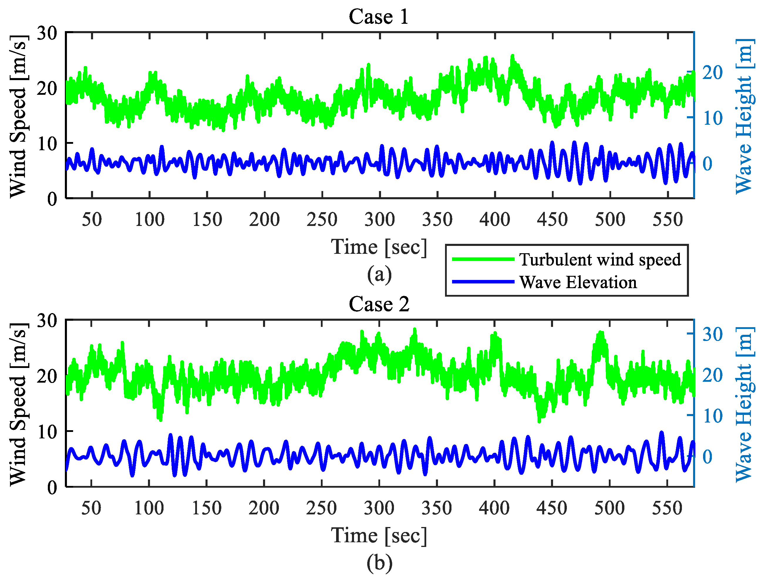
| Case No. | Wind Speed (m/s) | Turbulence Intensity (%) | Wave Height Hs (m) | Peak Spectral Period Tp (s) |
|---|---|---|---|---|
| 1 | 18 | 12.733 | 6 | 10 |
| 2 | 20 | 12.36 | 9 | 13 |
| Pitch System | Performance Indicators | CSM Observer | STSM Observer | ASTSM Observer |
|---|---|---|---|---|
| Pitch system 1 | 5.64 | 0.26 | 0.16 | |
| 0.16 | 0.01 | 0.01 | ||
| Pitch system 2 | 49.2 | 0.38 | 0.02 | |
| 13.17 | 0.11 | 0.004 | ||
| Pitch system 3 | 6.22 | 0.39 | 0.22 | |
| 0.15 | 0.03 | 0.02 |
Disclaimer/Publisher’s Note: The statements, opinions and data contained in all publications are solely those of the individual author(s) and contributor(s) and not of MDPI and/or the editor(s). MDPI and/or the editor(s) disclaim responsibility for any injury to people or property resulting from any ideas, methods, instructions or products referred to in the content. |
© 2023 by the authors. Licensee MDPI, Basel, Switzerland. This article is an open access article distributed under the terms and conditions of the Creative Commons Attribution (CC BY) license (https://creativecommons.org/licenses/by/4.0/).
Share and Cite
Liu, S.; Han, Y.; Ma, R.; Hou, M.; Kang, C. A Novel Composite Pitch Control Scheme for Floating Offshore Wind Turbines with Actuator Fault Consideration. J. Mar. Sci. Eng. 2023, 11, 2272. https://doi.org/10.3390/jmse11122272
Liu S, Han Y, Ma R, Hou M, Kang C. A Novel Composite Pitch Control Scheme for Floating Offshore Wind Turbines with Actuator Fault Consideration. Journal of Marine Science and Engineering. 2023; 11(12):2272. https://doi.org/10.3390/jmse11122272
Chicago/Turabian StyleLiu, Shuang, Yaozhen Han, Ronglin Ma, Mingdong Hou, and Chao Kang. 2023. "A Novel Composite Pitch Control Scheme for Floating Offshore Wind Turbines with Actuator Fault Consideration" Journal of Marine Science and Engineering 11, no. 12: 2272. https://doi.org/10.3390/jmse11122272
APA StyleLiu, S., Han, Y., Ma, R., Hou, M., & Kang, C. (2023). A Novel Composite Pitch Control Scheme for Floating Offshore Wind Turbines with Actuator Fault Consideration. Journal of Marine Science and Engineering, 11(12), 2272. https://doi.org/10.3390/jmse11122272