Article

Wavelet Neural Network-Based Half-Period Predictive Roll-Reduction Control Using a Fin Stabilizer at Zero Speed

1
College of Intelligent System Science and Engineering, Harbin Engineering University, Harbin 150001, China
2
College of Mechanical Electrical Engineering, Tangshan University, Tangshan 063000, China
3
Shanghai Merchant Ship Design and Research Institute, Shanghai 201203, China
*
Authors to whom correspondence should be addressed.
J. Mar. Sci. Eng. 2023, 11(11), 2205; https://doi.org/10.3390/jmse11112205
Submission received: 18 September 2023 / Revised: 31 October 2023 / Accepted: 18 November 2023 / Published: 20 November 2023
(This article belongs to the Section Ocean Engineering)

Abstract

:
Among the commonly used ship-stabilizing devices, the fin stabilizer is the most effective. Since the lift force of the conventional fin stabilizer is proportional to the square of the incoming flow velocity, it has a better anti-rolling effect at higher speeds but a poor anti-rolling effect at low speeds and even no effect at zero speed. A combination of modelling analysis, simulation, and a model ship experiment is used in this paper to study the zero-speed roll-reduction control problem of the fin stabilizer. A simulation model of the rolling motion of a polar expedition ship is established. The lift model of the fin stabilizer at zero speed is established using the theory of fluid mechanics. The proportional–integral–differential (PID) controller is selected to control the fin to achieve zero-speed roll reduction. To obtain a better anti-rolling control effect under variable sea conditions, a wavelet neural network (WNN)-based half-period prediction algorithm is adopted to update and adjust PID control parameters in real time. A simulation was carried out, and the effectiveness of the proposed predictive control algorithm is proved. A reduced-scale ship model was established to carry out the water tank experiment, and the results verify the theoretical analysis and simulation. The results also verify the effectiveness of the proposed control strategy.

1. Introduction and Background

1.1. Rolling and Its Harm

Due to the ship’s geometric characteristics, its roll damping is relatively tiny, and it is easy to produce a violent roll when it is interfered with by the sea winds, currents, and waves during marine navigation [1]. Ship rolling will increase the probability of crew seasickness and increase the risk of cargo boxes falling from container ships. For warships, it affects the accuracy of shipborne weapons and the take-off and landing of carrier-based aircraft [2].

1.2. Anti-Rolling Device

To reduce ship roll motion, devices such as gyrostabilizers [3], Magnus rotating roll stabilizers [4,5], anti-rolling tanks [6], and fin stabilizers [7] have been designed and manufactured. Among them, the fin stabilizer is the most widely used and effective anti-rolling device currently in use [2,8]. The proportion of its occupied displacement is tiny compared with other anti-rolling devices, and it has no impact on the initial stability of the ship. Therefore, its installation does not need to consider the impact on the ship’s stability. However, due to the limitation of the traditional fin’s hydrodynamic mechanism, its anti-rolling effect is poor at low speed, and there is even no effect at zero speed [1,9,10].
With the development of ship roll-reduction technology, more and more fin stabilizers need to function at low speed. In addition to fin shape factors, the study of low-speed control strategies for fin stabilizers is particularly important. Most traditional ship roll-reduction devices have sound roll-reduction effects only in a specific speed range, while the roll-reduction effect decreases in other speed ranges. In order to adapt to the diversification of ship development and meet the needs of ship operation under zero navigation, researchers have developed a variety of zero-speed roll-reduction devices. The gyrostabilizer has a good anti-rolling effect at zero speed but is limited by its weight, structure, and energy consumption [3]. The moving weight has the effect of anti-rolling at all speeds and in all the berths but simultaneously has relatively high power consumption [2,7]. The anti-rolling tank can achieve roll reduction at all speeds and has the advantages of simple structure and low cost, but it needs to occupy an ample space within the ship [6,11]. The Magnus rotor has good roll-reduction effect at low speed, but it needs to swing at zero speed to produce lifting force, and it produces much resistance at high speeds [4,5,12].

1.3. Roll-Reduction Control at Zero Speed

VT Naiad Marine first developed a zero-speed fin stabilizer in 1998 and carried out a real ship test on the yacht Boadicea, achieving an excellent anti-rolling effect [13,14]. To achieve zero-speed roll reduction, the fin stabilizer quickly beats the fluid and generates a stable torque. The resistance generated by the flapping fluid can resist the disturbing torque of the sea waves [14,15]. In order to obtain the greatest anti-rolling force possible, the zero-speed fin stabilizer has a smaller aspect ratio than conventional fins, and the fin shaft is closer to the leading edge. A small aspect ratio can reduce the navigation resistance, but due to the reduction of the lift coefficient, the anti-rolling effect at medium and high speeds is reduced [16]. Traditional fin stabilizers are usually designed for medium and high speeds, and the aspect ratio is large, especially for the retractable fin stabilizer. This makes its anti-rolling effect at zero and low speeds poor. This study addresses the control challenge of reducing ship roll motion at zero speed, especially for ships equipped with conventional fin stabilizers.
In addition, traditional PID controllers are designed for linear ship models, determining parameters, and specific sea conditions. The traditional method uses a PID control algorithm to design its controller. Due to its simple structure, fast calculation, and easy engineering implementation, the PID control algorithm is still the most important control algorithm for the fin stabilizer control system [2]. However, in practical applications, ship parameters are time-varying, nonlinear, and affected by the sea conditions, resulting in uncertainties in ship parameters. As a result, the fin stabilizer system can only have an excellent anti-rolling effect under specific conditions, and its control effect will be reduced when the external sea conditions change significantly. In view of the hazards of rolling and the time-varying and nonlinear characteristics of the ship rolling motion, accurate prediction of ship state is of great significance to ship navigation safety. Early predictions of ship attitude mainly included the convolution method [17], time series analysis method [18], and Kalman filter method [19]. With the development of artificial intelligence technology, machine learning theories such as neural networks and support vector machines have also been widely used in ship attitude prediction [20,21,22,23]. Among them, the neural network method has the advantages of strong learning ability and high adaptability, and has high application value in nonlinear research [24]. Wavelet neural networks, first proposed by Zhang and Nenveniste, are categorized as feedback neural networks, but do not use the traditional Sigmoid function, instead using the wavelet basis function as the conversion function [25]. In complex system modeling, wavelet neural networks have good local time–frequency characteristics, so they have received more and more attention and research. Zhang et al. based their research on wavelet neural networks combined with MMG model research to predict ship motion [26]. Zhang et al. predicted ship motion in real time based on a wavelet neural network [27]. Yin et al. studied and predicted ship roll motion based on wavelet transform and RBF neural networks [28]. Inoussa et al. used wavelet neural networks to model and forecast five different time series [29]. Zhang et al. proposed time-delay wavelet neural networks to study and predict ship motion [30]. Huang et al. applied a wavelet neural network to predict ship rolling motion online [31]. Cao et al. realized real-time prediction of ship motion based on adaptive wavelet transform and dynamic neural networks [32]. Some experts and scholars have begun to try to use the latest technological advancements and frameworks such as artificial intelligence (AI) and deep learning to optimize vessel operations [33,34].

1.4. Research Content and Arrangement

In this paper, aiming at addressing the poor effect of traditional fin stabilizers at zero speed, we propose a rolling period prediction algorithm based on a wavelet neural network to improve the rolling effect of fin stabilizers at zero speed. A combination of modelling analysis, simulation, and model ship experiment was used to study the zero-speed roll-reduction control problem of the fin stabilizer. Firstly, the mathematical model of fin force at zero speed and ship roll motion was established. The traditional PID controller was adopted to control the fin. Considering the correlation between the parameters of the PID controller and the rolling period of the ship, a half-rolling period prediction algorithm based on wavelet neural networks is proposed. The ship roll cycle is predicted by well-trained wavelet neural networks, and the parameters of the PID controller are adjusted in real time to achieve better anti-roll control effect.
The paper structure is arranged as follows. Section 2 obtains the model of ship roll motion and fin force at zero speed. Section 3 establishes the zero-speed roll-reduction system and presents the design of a PID controller based on a wavelet neural network. Section 4 gives and analyzes the results of simulations and model ship tank experiments. Finally, the conclusion is given.

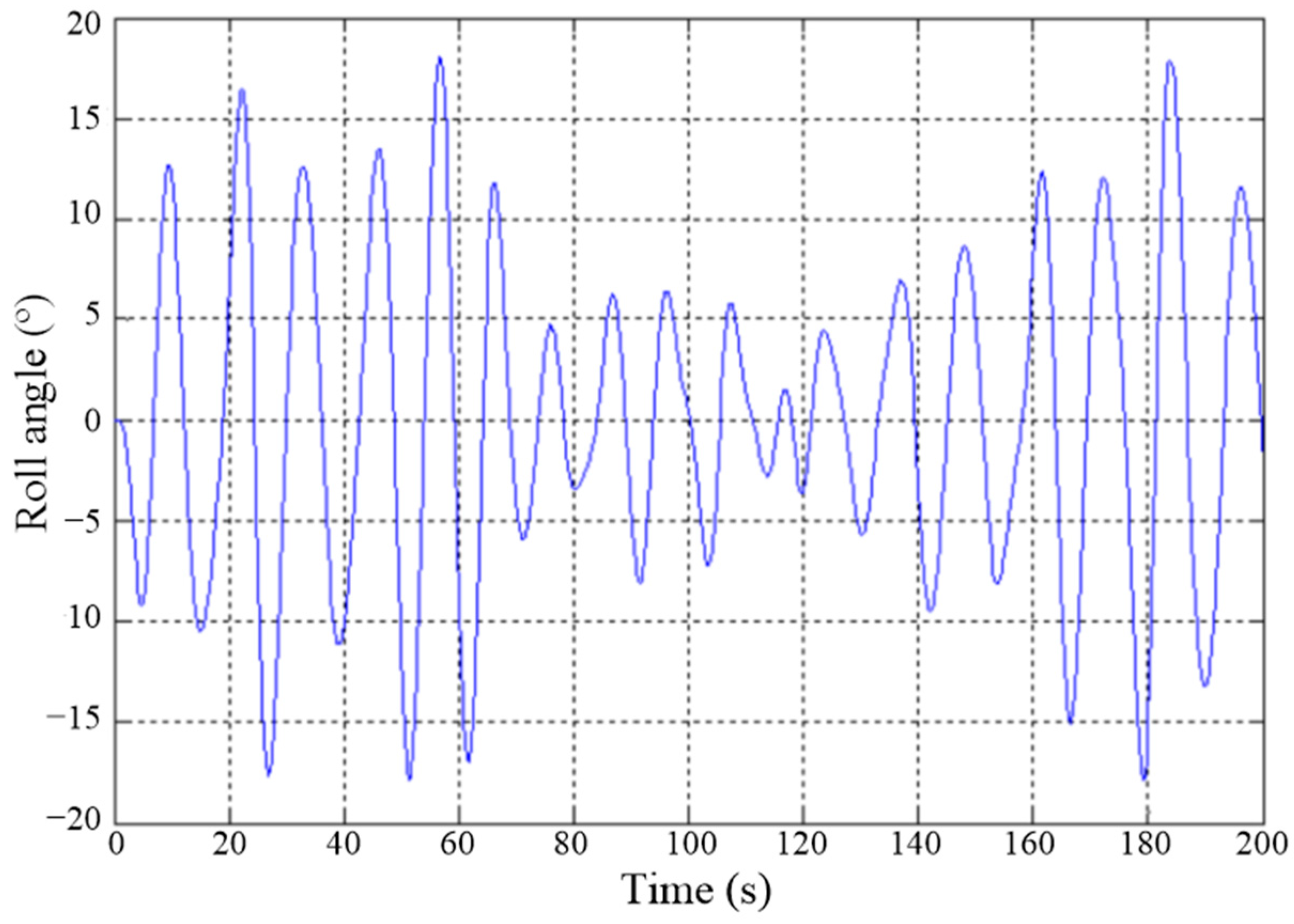
2. Modeling of Ship Rolling Motion

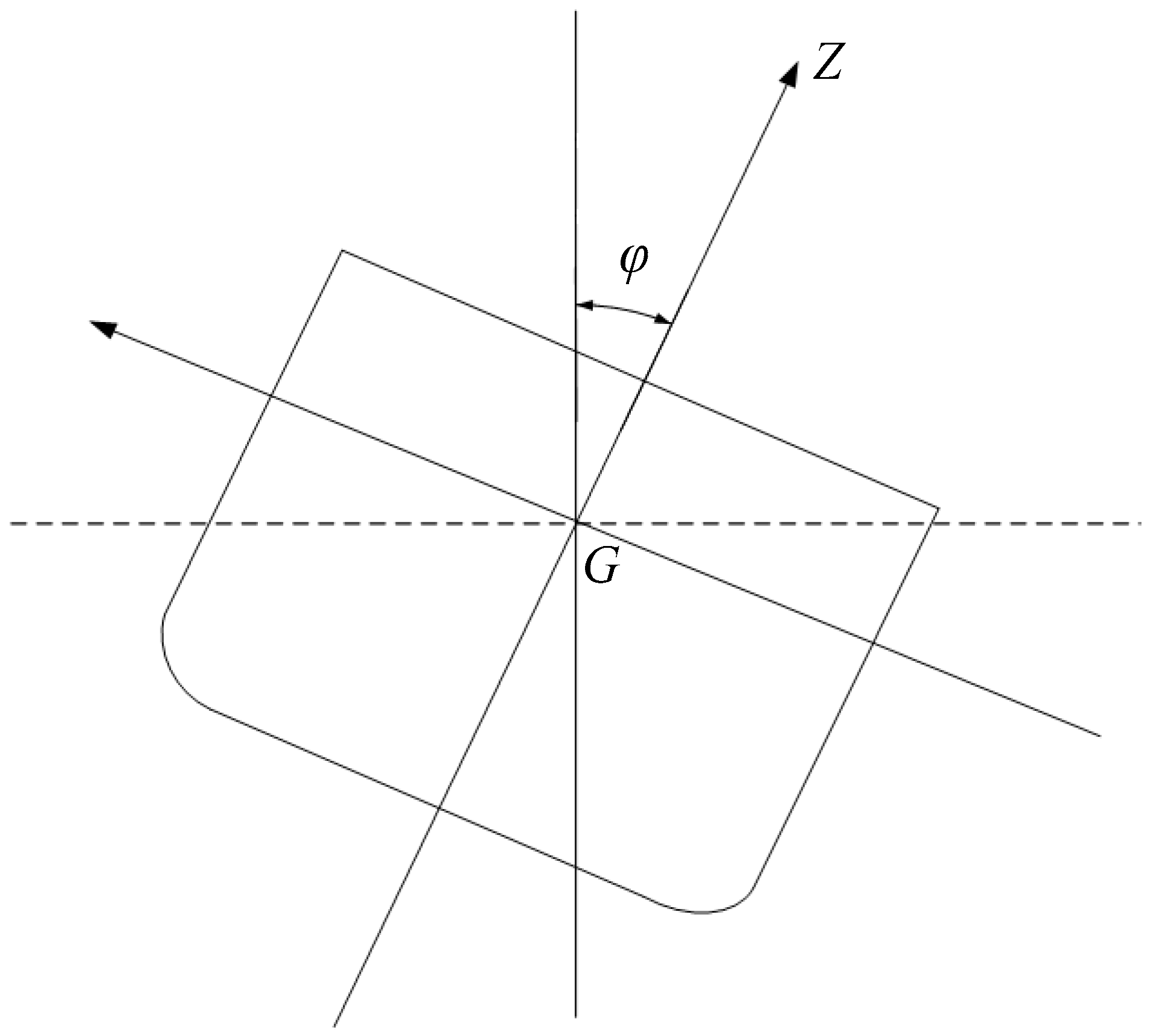
2.1. Mathematical Model of Ship Roll Motion

Ships sailing at sea experience rolling due to interference from the marine environment, as shown in Figure 1, where G is the center of gravity of the ship and φ is the roll angle. It is stipulated that the clockwise direction is positive, and the counter-clockwise direction is negative when looking from stern to bow. Ship roll is mainly affected by inertia moment, damping moment, and restoring moment [2].
According to the principle of rotating balance of objects, the balance condition of the ship is that the sum moment is zero. Therefore, the rolling motion can be expressed as [2]:
I x x + J x x φ .. + 2 N φ . + D h φ = D h α m
where Ixx and Jxx are the moment of inertia and additional moment of inertia, respectively, N is the roll damping coefficient, D and h are the displacement and initial metacentric height, respectively, αm is the wave slope angle, and φ ˙ and φ ¨ are the roll rate and roll acceleration, respectively.
Under zero initial condition, perform the Laplace transform to Equation (1), and we can obtain:
W φ ( s ) = φ ( s ) a m ( s ) = 1 K φ 2 s 2 + 2 B 44 K φ s + 1
where 1/Kφ represents the natural rolling frequency and B44 represents the dimensionless roll damping coefficient.
K φ = I x x + J x x D h , 2 B 44 = 2 N D h I x x + J x x
Equation (2) gives the equation of ship rolling motion under wave disturbance. In this paper, a polar exploration ship is selected to study the rolling characteristics at zero speed. The ship parameters are given in Table 1, where OG is the vertical distance between the rolling axis and the still water surface.
Incorporating the ship parameters, the ship roll model at zero speed can be obtained as:
W φ 0 ( s ) = 1 3.9291 s 2 + 0.4757 s + 1

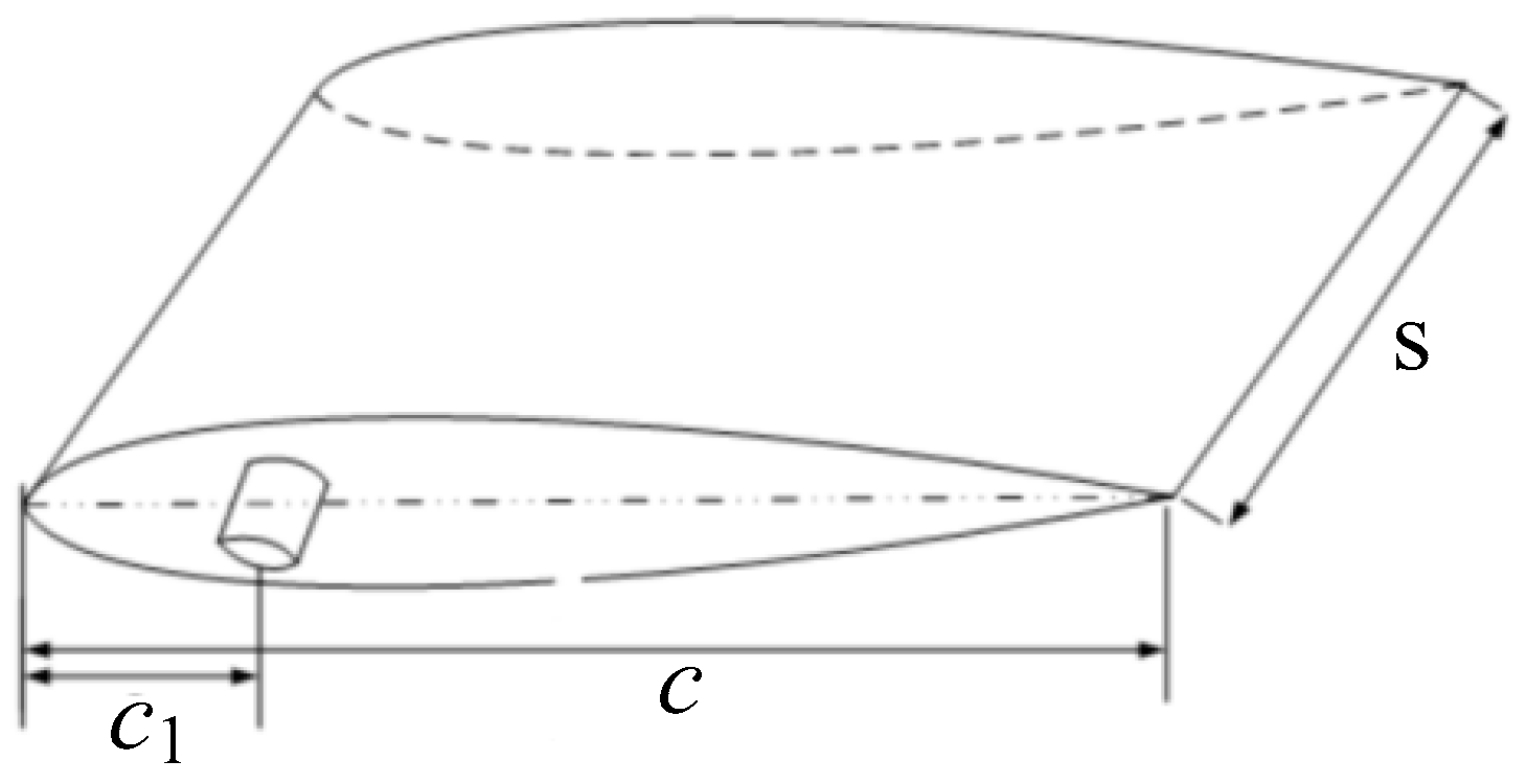
2.2. Mathematical Model of Fin Force

According to the theory of fluid mechanics, the force generated on the fin rotating around the fin axis in water is mainly composed of shape resistance, vortex resistance, and additional mass force [35,36]. This paper discusses the hydrodynamic solution of an NACA (National Advisory Committee for Aeronautics) airfoil shown in Figure 2, where c is the chord, c1 is the distance between the fin shaft and the leading edge, and s is the span.

2.2.1. Shape Resistance

As shown in Figure 3, for a rotating fin, the fluid will produce a reaction force perpendicular to the fin surface, mainly related to the rotational speed and fin shape, known as shape resistance. Taking the fin shaft as the boundary, the fin stabilizer can be divided into two parts: I and II. The shape resistance Fsr can be calculated as [16]:
F s r = 1 6 C d ρ s ω 2 c c 1 3 c 1 3
where Cd is the resistance coefficient, ρ is the fluid density, and ω is fin angular velocity.

2.2.2. Vortex Resistance

As shown in Figure 4, in the non-ideal fluid, the existence of a vortex will increase the resistance of fin area movement, which will increase the fin shape resistance. The fin can be divided into two parts, Part I and Part II, bounded by the fin shaft. Considering the size of these two parts, the vortex resistance of Part I can be ignored. Therefore, the vortex resistance can be calculated as [36,37]:
F v r = 1 6 ρ s ω 2 3 k 2 c c 1 2 3 k 2 2 c c 1 + k 2 3 c 1 3
where k2 is the length of the vortex of Part II along the chord direction.

2.2.3. Added Mass Resistance

The movement of the fin will change the state of the fluid around it. However, the inertia of the fluid hinders the state change. This adversarial effect creates added mass resistance [16,36]. According to [16], the added mass resistance can be approximately calculated as:
F a m r = 1 8 k a π ρ e c 2 c 2 c 1 ω ˙
where ka is a coefficient related to the fin angular velocity.

2.2.4. Hydrodynamic Force

The hydrodynamic force can be obtained by adding the three parts of resistance as follows:
F = 1 6 C d ρ s ω ω c c 1 3 c 1 3 + 1 8 k a π ρ e c 2 c 2 c 1 ω ˙ + 1 6 ρ s ω ω 3 k 2 c c 1 2 3 k 2 2 c c 1 + k 2 3 c 1 3
where the ω2 is replaced by ω|ω| considering the movement direction.
It can be seen from the above equation that the total hydrodynamic force is quantitively related to the fin’s rotating angular velocity and acceleration. Their relationship is nonlinear, which brings great difficulty to the controller design.

3. Zero-Speed Roll-Reduction Control Using Fin Stabilizer

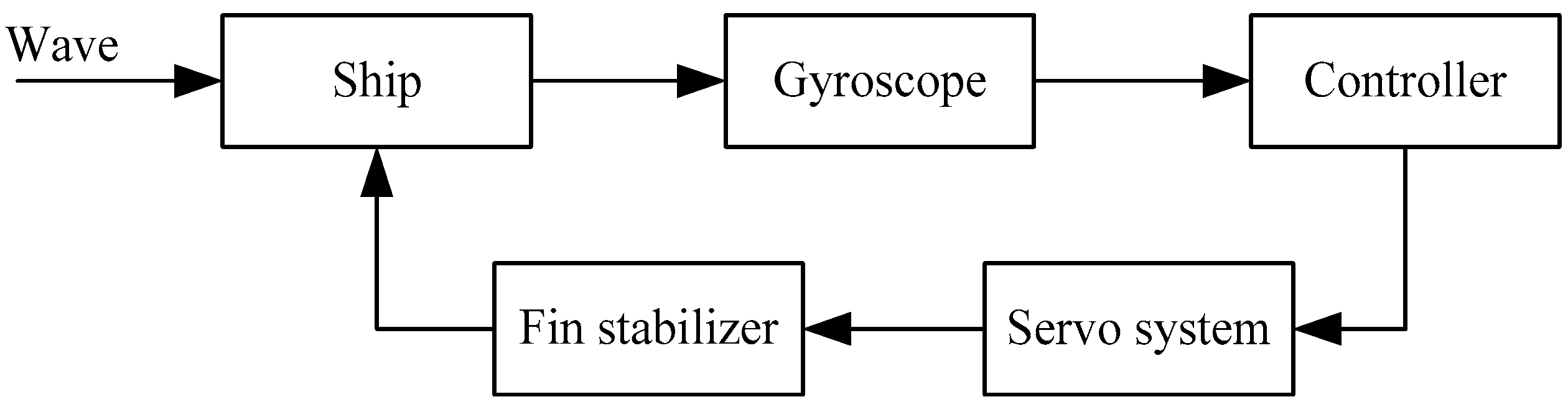
3.1. Mathematical Model of Roll-Reduction Control System

The zero-speed roll-reduction control block diagram using fins is shown in Figure 5. The angular velocity gyroscope detects the ship’s rolling and transmits it to the controller in the form of an electric signal. The controller calculates the control signal according to the received rolling information and sends it to the servo system. Subsequently, the fin acts under the drive of the servo system to resist the action of waves.

3.1.1. Ship Rolling Motion Equation

According to the principle of torque confrontation, the rolling motion with a fin can be expressed as follows [2]:
I t φ + 2 B 44 φ + D h φ = M w + M f i n
where Mfin is the stabilizing moment caused by fin stabilizers.

3.1.2. Angular Velocity Gyroscope

The primary function of angular velocity gyroscope is to detect the rolling information. Its transfer function is as follows [38]:
G r r g ( s ) = 400 s s 2 + 80 s + 4000

3.1.3. Servo System

The transfer function of the pump-controlled hydraulic cylinder system used in the fin stabilizer is as follows [39]:
G s s ( s ) = 1 s ( 0.0063 s + 1 ) ( s 2 33.4 2 + 0.6 s 33.4 + 1 )

3.1.4. Wave Disturbance

The motion of sea waves is somewhat complicated. When studying the effect of waves on ships, waves can be regarded as a stationary random process, which can usually be described by the power spectral density [1]. The Pierson–Moskowitz spectrum with one parameter of the significant wave height h1/3 is often used to describe the motion of ocean waves, and its expression is shown below [2]:
S ζ ( ω ) = 0.0081 g 2 ω 5 exp 3.11 h 1 / 3 2 ω 4
where g is gravity acceleration and ω is the wave frequency. The subscript ζ indicates that Equation (11) describes the wave-height spectrum, which is usually shifted to the wave-slope spectrum Sα(ω), as shown below, to simulate the rolling motion of the ship:
S α ( ω ) = ω 4 g 2 S ζ ( ω )
The sea wave can be seen as a superposition of countless harmonic components with different frequencies and phases. For a sailing ship, the frequency of encountering waves is not the same as the actual frequency of waves. The encounter frequency ωe can be obtained as:
ω e = ω ω 2 V g cos χ
where χ is the encounter angle.
The wave angle acting on the ship can be calculated as:
α t = i = 1 N 2 S α ω Δ ω cos ω e i t + ε i
where N is the number of superimposed regular waves, and ωei and εi are the encounter frequency and random phase of the ith regular waves, respectively.

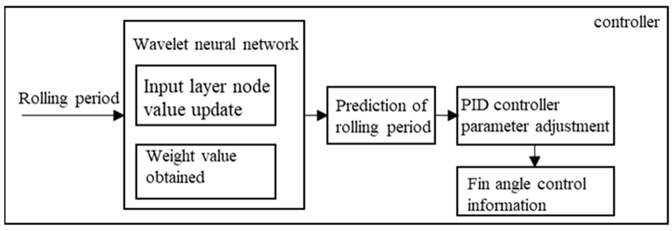
3.2. Controller Design

3.2.1. PID Controller

The expression of using the traditional PID control algorithm to control the fin stabilizer is as follows [2,38]:
M f i n = K P ( φ d φ ) K D φ + K I 0 t ( φ φ ( t ) ) d t
where φd = 0 is the reference value of roll angle. KP, KI, and KD are the controller parameters to be adjusted and can be obtained by the following empirical formula:
ω φ = K P T ,   B 44 = 1 + K D 2 T K P ,   K I = K P 10 ω φ
where T is the roll period.
Considering the time-varying nature of ship roll periods caused by random waves, if the fixed constant T is used to design a PID controller, the effect of the control system can only be achieved in a particular sea state. To solve this problem, an adaptive algorithm based on a wavelet neural network is proposed. The future roll period is predicted by WNN, allowing real-time adjustment of control parameters to meet the roll-reduction control effect in multiple sea conditions.

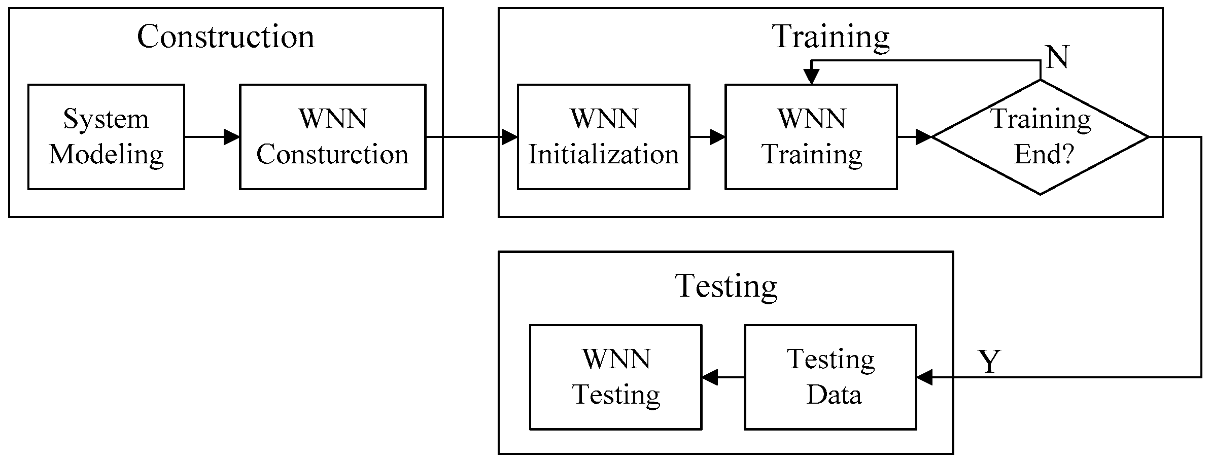
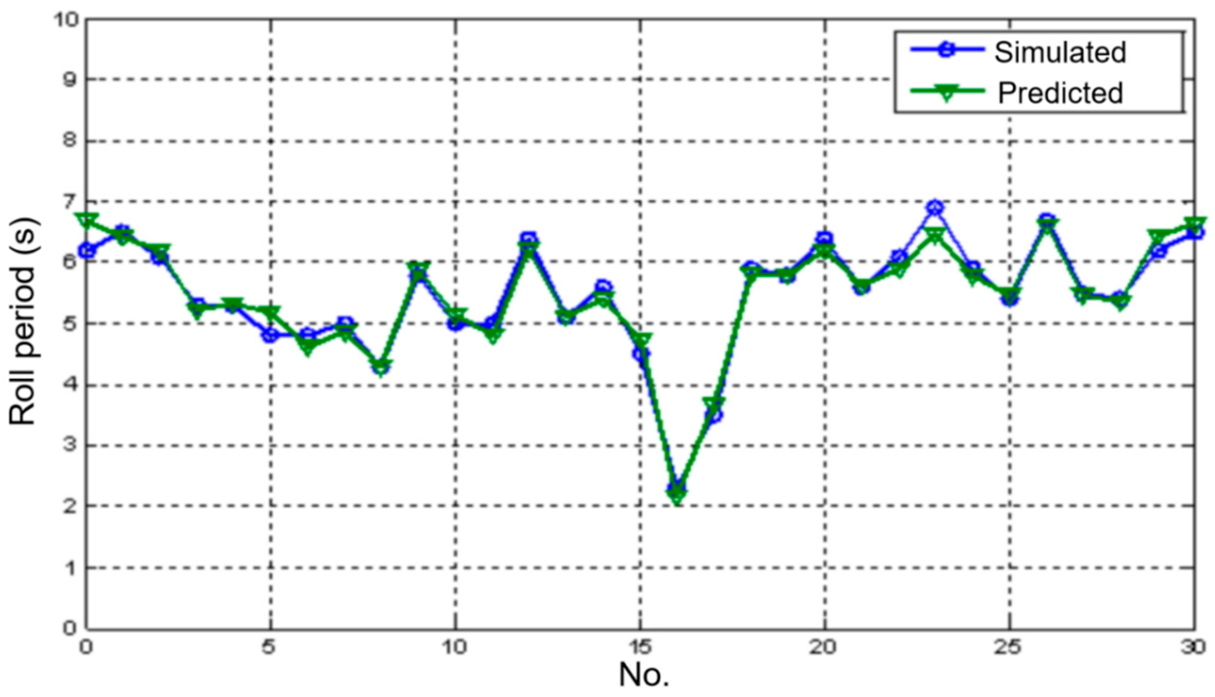
3.2.2. Half-Period Prediction Based on Wavelet Neural Network

The wavelet neural network is based on the topological structure of the back propagation (BP) neural network and uses the wavelet basis function as the transfer function of the hidden layer nodes. It has the characteristics of forward signal propagation with error backpropagation [40,41]. The topological structure of the WNN is shown in Figure 6. X1, X2, …, Xn and Y1, Y2, …, Ym are the input parameters and predicted outputs of the WNN, respectively. ωij and ωjk are the weight values of the WNN. WBF in Figure 6 represents wavelet basis function.
When the input signal sequence is xi (i = 1,2,…,k), the hidden layer output is:
h j = h j i = 1 k ω i j x i b j a j j = 1 , 2 , , l
where h(j) is the output of the jth node in the hidden layer, hj is the wavelet basis function, ωij is the connection weight value between the input layer and the hidden layer, and aj and bj are the expansion and translation factors, respectively. The Morlet mother wavelet basis function is used here.
h = cos ( 1.75 x ) e x 2 / 2
The output of WNN can be calculated as:
y k = i = 1 l ω i k h i k = 1 , 2 , , m
where ωik is the connection weight between the hidden layer and the output layer, H(i) is the output of the ith node in the hidden layer, and l and m are the number of nodes in the hidden layer and output layer, respectively.
The wavelet neural network uses a gradient correction method to modify the network’s weights and wavelet basis function parameters, so that the predicted output of the wavelet neural network continuously approaches the expected output.
The network prediction error can be calculated as:
e = k = 1 m y n k y k
where yn(k) is the expected output and y(k) is the predicted output of the WNN.
Therefore, the network’s weights and wavelet basis function parameters can be modified as:
ω n , k i + 1 = ω n , k i + Δ ω n , k i + 1
a k i + 1 = a k i + Δ a k i + 1
b k i + 1 = b k i + Δ b k i + 1
where Δ ω n , k i + 1 , Δ a k i + 1 , and Δ b k i + 1 can be calculated based on the network prediction error as follows:
Δ ω n , k i + 1 = η e ω n , k i
Δ a k i + 1 = η e a k i
Δ b k i + 1 = η e b k i
where η is the learning rate.
The roll period prediction algorithm based on the wavelet neural network is shown in Figure 7, which mainly includes the construction, training, and testing of the WNN.
The construction of wavelet neural networks determines the structure of wavelet neural networks. The wavelet neural network used in this paper includes an input layer, a hidden layer, and an output layer. For wavelet neural networks, the selection of network layers and the number of neural nodes in each layer are two very important aspects. According to the analysis in Section 3.2.1, the key to adjusting control parameters is to obtain the rolling period of the ship, which is also the purpose of introducing a wavelet neural network. Therefore, the number of output layer nodes was selected as one. After many attempts, considering accuracy and timeliness, the number of input layer nodes was selected as five. According to [42], if the number of input layer nodes is m, the number of hidden layer nodes can be determined to be about 2m + 1. In this paper, the number of the input layer nodes is five; therefore, the number of the hidden layer nodes can be chosen as 11. After many attempts, we found that the effect is better when the number of hidden layer nodes is selected as 15. The network weight and learning rate were selected as 0.01 and 0.001.
By simulating the ship rolling motion under irregular waves, a series of a time sequence of the ship rolling zero-crossing point was obtained. The simulation result of the ship roll motion with a significant wave height of 2.5 m and the encounter angle of 90° is shown in Figure 8.
Some roll period data are shown in Table 2. These data can be used for the training and validation of wavelet neural networks. From the simulation results of the ship’s rolling motion, 500 rolling periods were extracted, of which the first 450 values were used as training samples, and the last 50 values were used as test data.
Through good training, the prediction results are shown in Figure 9. The simulation results demonstrate the effectiveness of roll period prediction based on the WNN.

3.2.3. Zero-Speed Fin Stabilizer Controller

The controller structure is shown in Figure 10. The controller needs to judge the roll angle information first. When the roll angle is zero, the current time is recorded. When the controller detects that the roll angle information is zero, the time when the second roll angle is zero is recorded. The rolling period can be obtained by the difference between the time and the previous time. Taking the rolling period as the input of the WNN and combining the weight matrix obtained off-line, the next rolling period of the ship can be predicted. The PID control parameters can be solved and updated in real-time according to the formula. The new PID parameters are used to solve the fin angle control signal size.

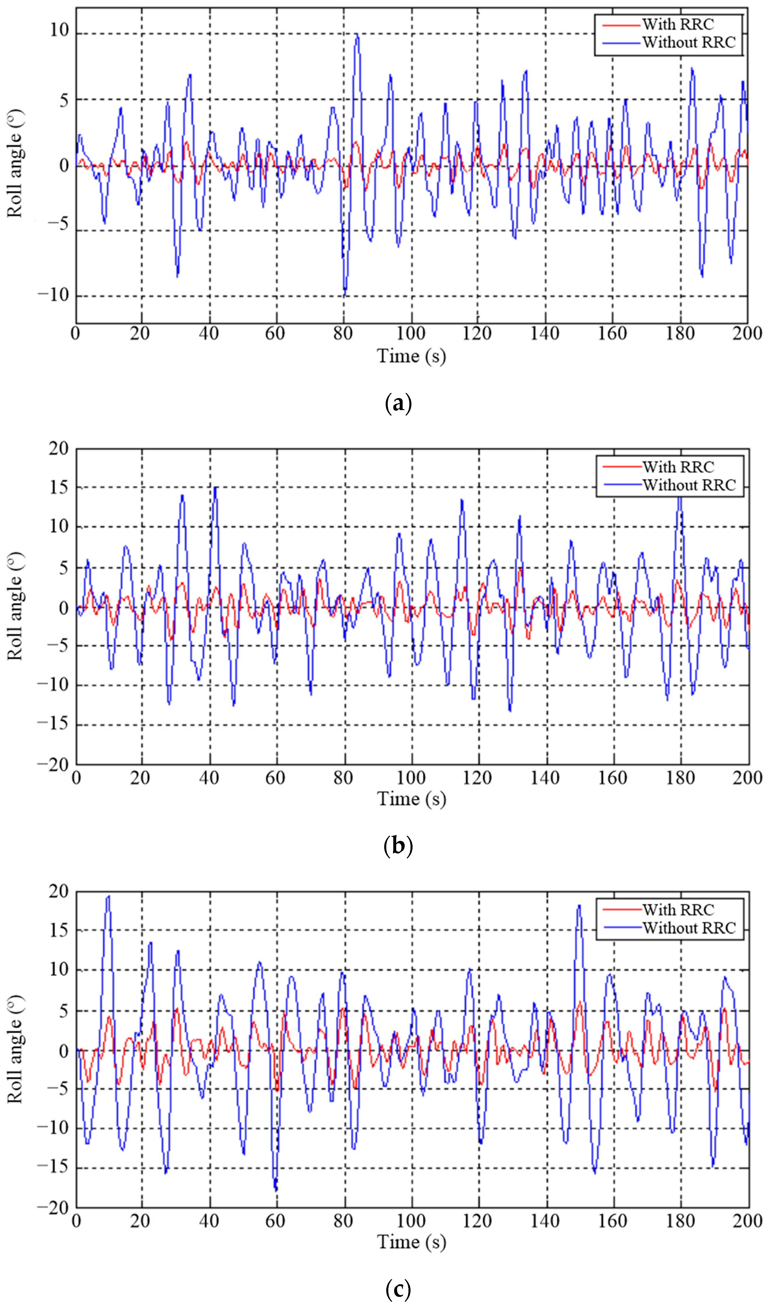
4. Simulation and Experiments

4.1. Simulation and Discussion

To verify the effectiveness of the designed zero-speed roll-reduction controller, the simulation model of a polar ship was established. The zero-speed roll-stabilization simulation under different sea conditions was carried out. The simulation results with significant wave heights of 2 m, 2.5 m, and 3 m are shown in Figure 11, where RRC represents roll reduction control. The following formula is used to evaluate the anti-rolling effect γ:
γ = σ u σ s σ u × 100 %
where σs and σu are the RMS of the roll angle with and without RRC, respectively.
The simulation results show that the designed WNN-based zero-speed roll-reduction controller can effectively reduce the roll motion of the polar ship. The roll angles before and after the stabilization under a significant wave height of 2 m are 6.18° and 1.62°, respectively, and the anti-rolling effect is about 73.8%. When the significant wave height is 2.5 m, the roll angles before and after the stabilization are 11.55° and 3.36°, respectively, and the anti-rolling effect is about 70.9%. The roll angles before and after the stabilization under a significant wave height of 3 m are 13.84° and 4.32°, respectively, and the anti-rolling effect is about 68.8%.
It can be seen that the anti-rolling effect decreases to a certain extent with the increase of sea conditions. However, the overall anti-rolling effect is about 70%, indicating that the proposed control strategy has a better effect under changing sea conditions.

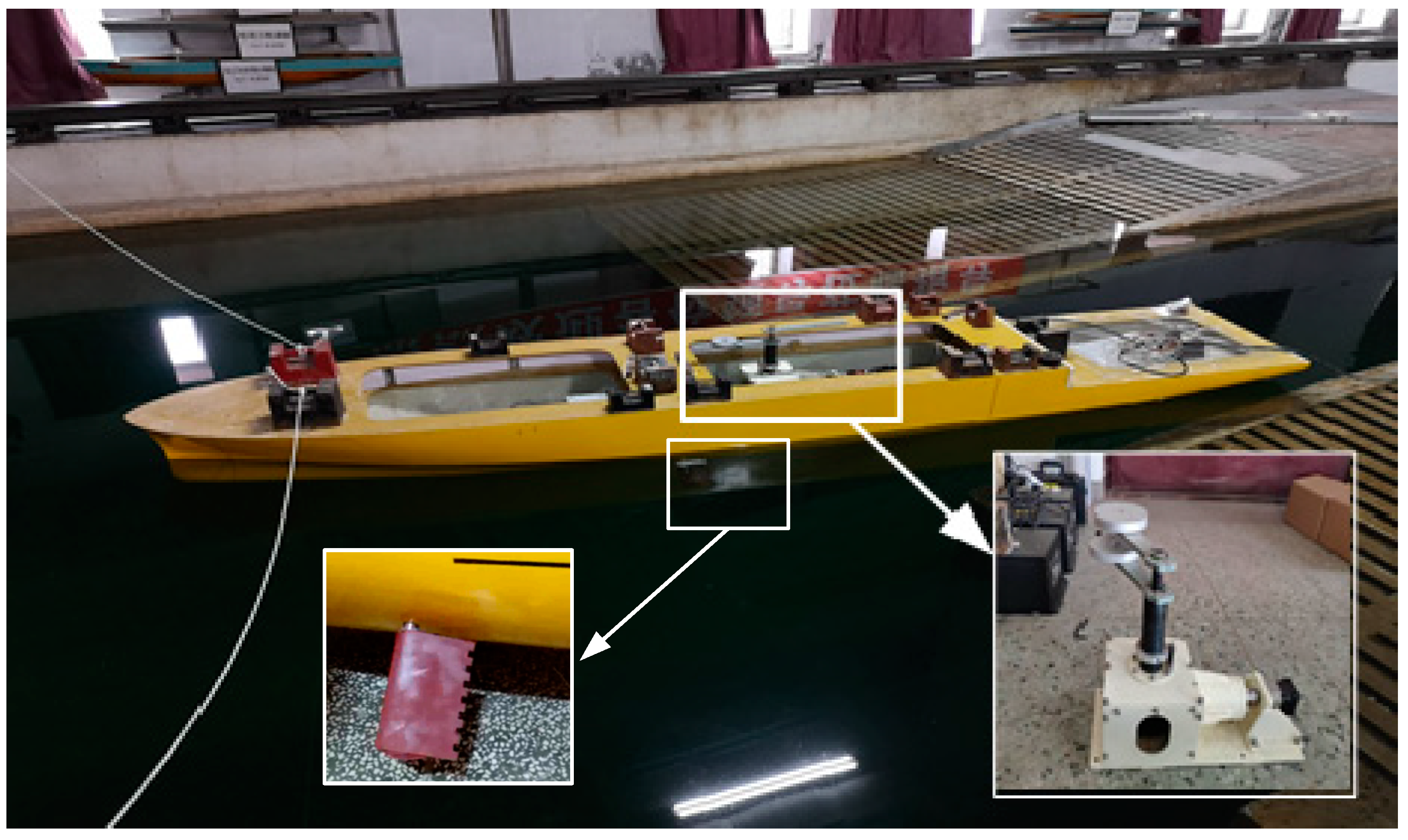
4.2. Model Ship Tank Experiment

To further verify the method’s practicability and effectiveness, model tank experiments were carried out. A 1:24 scale model of the polar exploration ship was built. As shown in Figure 12, the model ship mainly includes the hull, a pair of fins and their driving device, a forced rolling device, a roll attitude sensor, and data-acquisition and other modules.
The natural roll period of the model ship was obtained by the free decay test, and was about 2.5 s. As shown in Figure 10, the forced rolling device drives the weights to rotate periodically through the rotating arm to generate disturbance moments to force the hull to roll. The relationship of the roll angle and time of the model ship under different rotating periods of the forced rolling device is given in Figure 13. The relationship of the maximum roll angle of the model ship and the rotating period of the forced rolling device is given in Figure 14. It can be seen that when the rotation period of the forced rolling device is consistent with the natural roll period of the model ship, the model ship rolls most violently, and the corresponding roll angle is the largest.
The period of the forced rolling equipment was set to be the same as the rolling period of the model ship, to maximize the rolling motion of the model ship. Several anti-rolling control experiments were carried out, and the experimental results of one group are shown in Figure 15.
It can be seen from Figure 15 that the model’s rolling was significantly reduced after starting the roll reduction control. The peak roll angles with and without roll reduction control were about 4.1° and 12.5°, respectively. The anti-roll effect of this group of experiments was about 67.2%. The results of the model ship experiment are consistent with the simulation results, indicating that the proposed half-period predictive roll-reduction control strategy based on the WNN is applicable and practical.
Liang et al. showed that the anti-rolling effect of a small aspect ratio fin stabilizer in a model ship anti-rolling test in still water was 71.7% [43]. In terms of anti-rolling effect, that is higher than the results of the tank experiment in this paper. In this context, the anti-rolling effect of the pool test under the control of the proposed algorithm can reach 67.2%, which is quite satisfactory.

5. Conclusions

In this paper, roll-reduction control using fin stabilizers at zero speed is studied through a combination of model analysis, simulation, and model ship experiment. The mathematical model of the rolling motion of a polar exploration ship was established by analyzing the forces and moments on the hull. The hydrodynamic force model on the fin was established based on the hydromechanics theory when the fin stabilizer flaps at zero speed. On this basis, the simulation model of the ship’s zero-speed roll-reduction control system is established. The PID controller was adopted to control the fins to stabilize the ship. The parameters of the traditional fin stabilizer PID controller are generally designed and determined for typical sea conditions, making its anti-rolling control effect decrease when the sea conditions change. A half-period predictive anti-rolling control strategy based on a wavelet neural network is proposed considering the relationship between PID controller parameters and ship rolling period. The wavelet neural network is trained to predict the next roll period, and the control parameters of the PID controller are adjusted in real time according to the predicted roll period to adapt to changes in sea conditions. The simulation results show that the proposed control strategy can effectively reduce the roll motion of the ship at zero speed, and the anti-rolling effect can reach about 73.8%. The model ship tank experiment results further verify the effectiveness and applicability of the proposed control strategy.
In this study, only one parameter of roll period was used as the input for the wavelet neural network, and the factors affecting roll period, such as speed, wind speed and so on, were not considered. In the future, a more refined and informed model can be obtained by incorporating other influencing factors. In addition, considering the coupling relationship between the various degrees of freedom of the ship, the attitude control of multiple degrees of freedom at zero speed can be considered in the future.

Author Contributions

Conceptualization, S.Z., M.G. and P.Z.; methodology, S.Z.; software, S.Z.; validation, S.Z., P.Z. and M.G.; formal analysis, S.Z. and P.Z.; investigation, S.Z., P.Z. and M.G.; resources, S.Z. and M.G.; data curation, S.Z. and P.Z.; writing—original draft preparation, P.Z. and S.Z.; writing—review and editing, P.Z., S.Z. and L.L.; visualization, S.Z. and P.Z.; supervision, S.Z. and L.L.; project administration, S.Z.; funding acquisition, S.Z., P.Z. and L.L. All authors have read and agreed to the published version of the manuscript.

Funding

This research was funded by the Doctorial Innovation Funds of Tangshan University under Grant 1402001, the Fundamental Research Funds for the Central Universities under grant HEUCFM170404 and Harbin Science and Technology Innovation Talent Research Special Fund under grant 2017RC2017XK009006.

Institutional Review Board Statement

Not applicable.

Informed Consent Statement

Not applicable.

Data Availability Statement

The authors confirm that the data supporting the findings of this study are available within the article.

Conflicts of Interest

The authors declare no conflict of interest.

References

  1. Perez, T. Ship Motion Control: Course Keeping and Roll Stabilisation Using Rudder and Fins; Springer: London, UK, 2005. [Google Scholar]
  2. Jin, H.; Yao, X. Ship Control Principle, 2nd ed.; Harbin Engineering University Press: Harbin, China, 2013. [Google Scholar]
  3. Talha, M.; Asghar, F.; Kim, S. Design of fuzzy tuned PID controller for anti rolling gyro (ARG) stabilizer in ships. Int. J. Fuzzy Log. Intell. Syst. 2017, 17, 210–220. [Google Scholar] [CrossRef]
  4. Liang, L.; Zhao, P.; Zhang, S.; Yuan, J.; Wen, Y. Simulation and analysis of Magnus rotating roll stabilizer at low speed. Ocean Eng. 2017, 142, 491–500. [Google Scholar] [CrossRef]
  5. Ozturk, D. Performance of a Magnus effect-based cylindrical roll stabilizer on a full-scale Motor-yacht. Ocean Eng. 2020, 218, 108247. [Google Scholar] [CrossRef]
  6. Gerrge, A.; Cho, I. Anti-sloshing effects of a vertical porous baffle in a rolling rectangular tank. Ocean Eng. 2020, 214, 107871. [Google Scholar] [CrossRef]
  7. Lewis, E. Principles of Naval Architecture, 2nd ed.; SNAME: Jersey City, NJ, USA, 1989; Volume 3. [Google Scholar]
  8. Perez, T.; Blanke, M. Ship roll damping control. Annu. Rev. Control. 2012, 36, 129–147. [Google Scholar] [CrossRef]
  9. Crossland, J. The effect of roll stabilization controllers on warship operational performance. Contr. Eng. Pract. 2003, 11, 423–431. [Google Scholar] [CrossRef]
  10. Zhang, S.; You, P.; Zhao, P.; Liang, L.; Li, R. Experimental study on the control form of fin stabilizer at zero speed. PLoS ONE 2018, 13, e0204446. [Google Scholar] [CrossRef]
  11. Moaleji, R.; Greig, A. On the development of ship anti-roll tanks. Ocean Eng. 2007, 34, 103–121. [Google Scholar] [CrossRef]
  12. Liang, L.; Jiang, Y.; Zhang, Q.; Le, Z. Aspect ratio effects on hydrodynamic characteristics of Magnus stabilizers. Ocean Eng. 2020, 216, 107699. [Google Scholar] [CrossRef]
  13. Dallinga, R. Roll Stabilization at Anchor: Hydrodynamic Aspects of the Comparison of Anti-Roll Tanks and Fins; Maritime Research Institute Netherlands: Amsterdam, The Netherlands, 2002. [Google Scholar]
  14. Ooms, J. The use of roll stabilisers fins at zero speed. In Quantum Controls BV, Nuth, Holland, Project; TU Delft Library: Delft, The Netherlands, 2002. [Google Scholar]
  15. Song, J.; Zhao, P.; Liang, L.; Ji, M. Force modeling of zero/low-velocity fin stabilizer and hydrofoil profile optimization. Ocean Eng. 2020, 213, 107635. [Google Scholar] [CrossRef]
  16. Jin, H.; Qi, Z.; Song, J. Ship Anti-Rolling Control Device and System at Zero Speed; National Defense Industry Press: Beijing, China, 2015. [Google Scholar]
  17. Kaplan, P. A study of prediction techniques for aircraft carrier motions at sea. J. Hydronautics 1969, 3, 121–131. [Google Scholar] [CrossRef]
  18. Yumori, I. Real time prediction of ship response to ocean waves using time series analysis. In Proceedings of the OCEANS 81, Boston, MA, USA, 16–18 September 1981; pp. 1082–1089. [Google Scholar]
  19. Triantafyllou, M.; Bodson, M.; Athans, M. Real time estimation of ship motions using Kalman filtering techniques. IEEE J. Ocean. Eng. 1983, 8, 9–20. [Google Scholar] [CrossRef]
  20. Masi, G.; Gaggiotti, F.; Bruschi, R.; Venturi, M. Ship motion prediction by radial basis neural networks. In Proceedings of the IEEE Workshop on Hybrid Intelligent Medels and Applications, Paris, France, 11–15 April 2011; pp. 28–32. [Google Scholar]
  21. Huang, B.; Zou, Z. Shipt-term prediction of ship pitching motion based on artificial neural networks. In Proceedings of the The 35th International Conference on Ocean, Offshore and Arctic Engineering, Busan, Republic of Korea, 19–24 June 2016. [Google Scholar]
  22. Xu, F.; Zou, Z.; Yin, J.; Cao, J. Identification modeling of underwater vehicles’ nonlinear dynamics based on support vector machines. Ocean Eng. 2013, 67, 68–76. [Google Scholar] [CrossRef]
  23. Hou, X.; Zou, Z. SUR-based identification of nonlinear roll motion equation for FPSOs in regular waves. Ocean Eng. 2015, 109, 531–538. [Google Scholar] [CrossRef]
  24. Huang, B. Online Modeling and Predicting of Ship Motions in Waves Based on Wavelet Neural Network; Shanghai Jiao Tong University: Shanghai, China, 2019. [Google Scholar]
  25. Zhang, Q.; Benveniste, A. Wavelet network. IEEE Trans. Neural Netw. 1992, 3, 889–898. [Google Scholar] [CrossRef] [PubMed]
  26. Zhang, T.; Wang, Z.; Wang, P. Pitch angle prediction of container ship based on improved wavelet neural network. J. Guangdong Ocean. Univ. 2022, 42, 117–121. [Google Scholar]
  27. Zhang, W.; Liu, Z. Online ship motion prediction based on wavelet neural network. J. Dalian Marit. Univ. 2013, 39, 25–28. [Google Scholar]
  28. Yin, J.; Perakis, A.; Wang, N. A real-time ship roll motion prediction using wavelet transform and variable RBF network. Ocean Eng. 2018, 160, 10–19. [Google Scholar] [CrossRef]
  29. Inoussa, G.; Peng, H.; Wu, J. Nonlinear times series modeling and predction using functional weights wavelet neural network-based state-dependent AR model. Neurocomputing 2012, 86, 59–74. [Google Scholar] [CrossRef]
  30. Zhang, W.; Liu, Z. Real-time ship motion prediction based on time delay wavelet neural network. J. Appl. Math. 2014, 2014, 176297. [Google Scholar] [CrossRef]
  31. Huang, B.; Zou, Z.; Ding, W. Online prediction of ship roll motion based on a coarse and fine tuning fixed grid wavelet network. Ocean Eng. 2018, 160, 425–437. [Google Scholar] [CrossRef]
  32. Gao, N.; Hu, A.; Hou, L.; Chang, X. Real-time ship motion prediction based on adaptive wavelet transform and dynamic neural network. Ocean Eng. 2023, 280, 114466. [Google Scholar] [CrossRef]
  33. Dimitrios, K.; Iraklis, V.; George, G.; Takis, J.; Constantine, D. Enabling digital twins in the maritime sector through the lens of AI and industry 4.0. Int. J. Inf. Manag. Data Insights 2023, 3, 100178. [Google Scholar]
  34. Ferrandis, J.; Triantafyllou, M.; Chryssostomidis, C.; Karniadakis, G. Learning functionals via LSTM neural networks for predicting vessel dynamics in extreme sea states. Proc. R. Soc. A 2019, 477, 20190897. [Google Scholar] [CrossRef]
  35. Dallinga, R. Roll Stabilization of Motor Yachts: Use of Fin Stabilizers in Anchored Conditions. MARIN: Wageningen, The Netherlands, 1998. Available online: http://http://resolver.tudelft.nl/uuid:3aa9c3a8-1653-4029-b347-82f4f35d45c4 (accessed on 19 October 2023).
  36. Wang, F.; Jin, H.; Qi, Z. Modeling for active fin stabilizers at zero speed. Ocean Eng. 2009, 36, 1425–1437. [Google Scholar]
  37. Song, J.; Jin, H.; Meng, L. Optimum design of aerofoil for fin stabilizer at whole speed range. Ship Build. China 2013, 54, 1–10. [Google Scholar]
  38. Jin, H.; Wang, K.; Ji, M. Application of Intelligent Technique to Fin Stabilizers; National Defense Industry Press: Beijing, China, 2003. [Google Scholar]
  39. Liang, L. Hydraulic Transmission and Electro-Hydraulic Servo System; Harbin Engineering University Press: Harbin, China, 2005. [Google Scholar]
  40. Zhao, Y.; Yang, Q.; Su, D.; Zou, L.; Wang, A. Rogue wave prediction based on wavelet neural network. J. Harbin Inst. Technol. 2021, 53, 112–117. [Google Scholar]
  41. Wang, X.; Shi, F.; Yu, L.; Li, Y. Matlab Neural Network Analysis of 43 Cases; Beijing University of Aeronautics and Astronautics Press: Beijing, China, 2013; pp. 279–287. [Google Scholar]
  42. Kong, L. Matlab Wavelet Analysis, Super Learning Manual; Posts & Telecom Press: Beijing, China, 2023. [Google Scholar]
  43. Liang, L.; Zhao, P.; Zhang, S.; Ji, M.; Song, J.; Yuan, J. Simulation and experimental study on control strategy of zero-speed fin stabilizer based on disturbance and compensation. PLoS ONE 2018, 14, e0204446. [Google Scholar] [CrossRef]
Figure 1. Ship rolling state diagram.
Jmse 11 02205 g001
Figure 2. NACA airfoil.
Jmse 11 02205 g002
Figure 3. Schematic diagram of shape resistance.
Jmse 11 02205 g003
Figure 4. Vortex at zero speed.
Jmse 11 02205 g004
Figure 5. Roll reduction control system.
Jmse 11 02205 g005
Figure 6. Structure of wavelet neural network.
Jmse 11 02205 g006
Figure 7. Algorithm flow of wavelet neural network.
Jmse 11 02205 g007
Figure 8. Simulation curve of ship rolling motion.
Jmse 11 02205 g008
Figure 9. Prediction results for the rolling half-period.
Jmse 11 02205 g009
Figure 10. Structure of fin stabilizer controller.
Jmse 11 02205 g010
Figure 11. Ship roll motion under different sea conditions. (a) h1/3 = 2 m. (b) h1/3 = 2.5 m. (c) h1/3 = 3 m.
Jmse 11 02205 g011
Figure 12. Model of the polar exploration ship.
Jmse 11 02205 g012
Figure 13. Roll response of model ships under different rotating periods.
Jmse 11 02205 g013
Figure 14. Relationship of the maximum roll angle and the rotation period.
Jmse 11 02205 g014
Figure 15. Results of anti-rolling experiment.
Jmse 11 02205 g015
Table 1. Ship parameters.
DescriptionSymbolValueDescriptionSymbolValue
Length of shipLpp109 mDisplacementD6500 t
Natural roll periodT12.5 sWidth of shipB19 m
Transverse metacentric heighth1.5 mDraftd6 m
Midship section coefficientCm0.98Square coefficientCb0.56
Bilge keel lengthlBk21.8 mBilge keel widthbBk0.49 m
OG/d1.38B/d3.25
lBk/Lpp0.2bBk/B0.025
Table 2. Part of the sample data of the rolling half-period.
No.Rolling Half-Period (s)No.Rolling Half-Period (s)No.Rolling Half-Period (s)
15.6115.9214.8
24.5125.4224.8
32.3136.7235.0
43.5145.5244.3
55.9155.4255.7
65.8166.2265.1
76.4176.5274.9
85.6186.1286.5
96.1195.3295.1
106.9205.3305.6
Disclaimer/Publisher’s Note: The statements, opinions and data contained in all publications are solely those of the individual author(s) and contributor(s) and not of MDPI and/or the editor(s). MDPI and/or the editor(s) disclaim responsibility for any injury to people or property resulting from any ideas, methods, instructions or products referred to in the content.

