Article

Theoretical Analysis of Plastic Behavior of Sandwich Beam with Metal Foam under Repeated Impacts

1
Key Laboratory of High Performance Ship Technology, Wuhan University of Technology, Ministry of Education, Wuhan 430063, China
2
School of Naval Architecture, Ocean and Energy Power Engineering, Wuhan University of Technology, Wuhan 430063, China
3
State Key Laboratory of Materials Synthesis and Processing, Wuhan University of Technology, Wuhan 430070, China
4
Marine Design and Research Institute of China, Shanghai 200021, China
*
Authors to whom correspondence should be addressed.
J. Mar. Sci. Eng. 2023, 11(10), 1974; https://doi.org/10.3390/jmse11101974
Submission received: 1 September 2023 / Revised: 23 September 2023 / Accepted: 8 October 2023 / Published: 12 October 2023
(This article belongs to the Special Issue Advances in Marine Mechanical and Structural Engineering)

Abstract

:
The phenomenon of repeated impacts on engineering structures is very common, especially in naval and ocean engineering. When marine structures are subjected to repeated impact loadings, deformation and damage will accumulate as the impact number increases, resulting in the failure and damage of the structures, even causing serious accidents. Based on the rigid-plastic assumption, a theoretical model is established to analyze the plastic mechanical behavior of metal foam sandwich beams (MFSBs) suffering from repeated impacts, in which the membrane factor method (MFM) is applied to derive analytical solutions for the plastic responses of MFSBs. The theoretical predictions agree well with the results of impact tests and numerical simulations, indicating that the theoretical model is accurate and reliable. In addition, the dynamic responses of MFSBs are analyzed based on the MFM, and the effects of the core strength and the face thickness on the deflection responses are determined. The results show that the dimensionless permanent deflection of MFSBs is sensitive to the core strength ratio and the face thickness ratio, and as the core strength ratio or the face thickness ratio increases, the dimensionless permanent deflection decreases gradually in an exponential form. In addition, the influence of the core strength ratio and face thickness ratio becomes more significant as the impact number increases. The proposed theoretical method can provide a theoretical reference and technical support for the design of metal foam sandwich structures with improved impact resistance under repeated impact loadings.

1. Introduction

Marine structures are frequently subjected to repeated impact loadings, such as from supply ships, dropped objects, and floe ice. During navigation and operation, damage will accumulate, resulting in the failure of the structures and even causing serious accidents. Therefore, it is necessary to study the dynamic behavior of marine structures under repeated impact loadings.
In order to investigate the dynamic behavior of marine structures subjected to repeated impacts, theoretical analysis, numerical simulations, and impact tests have been performed by many academics. Zhu [1] conducted repeated collision tests on fully clamped rectangular plates and developed a numerical program based on the finite difference method to study the dynamic behavior of ship plates subjected to repeated loadings, and an expression of permanent deflection was given. In order to investigate the effect of low temperatures, Truong et al. [2,3] performed experimental and numerical investigations on steel beam and grillage structures subjected to repeated lateral impacts under low temperatures. The results showed that the permanent deflections at low temperatures were smaller than those at room temperature, and the influence was enhanced with the increase in the impact number. Zhu et al. [4] carried out repeated-impact tests on stiffened plates and proposed a theoretical method based on inscribing and circumscribing a yield surface, which provided analytical predictions of the permanent deflection. Zeng et al. [5] conducted experiments on circular mild-steel plates with surface cracks suffering from repeated impacts at low temperatures, and the effects of low temperatures as well as surface cracks on the peak impact force and permanent deflection were determined.
Recently, the pseudo-shakedown phenomenon of structures, caused by repeated impacts, has attracted more and more attention. Jones [6] applied a rigid-plastic method of analysis to plates subjected to repeated mass impacts and discussed the occurrence conditions of the pseudo-shakedown phenomenon. The results showed that plates subjected to repeated identical mass impact loadings would not achieve a pseudo-shakedown state for most impact cases, except in the special case when a small enough impact energy could be absorbed. He and Soares [7,8,9,10] performed experimental and numerical studies on the dynamic behavior of beams under repeated impacts, and the phenomenon of pseudo-shakedown was discussed. Cai et al. [11] employed experimental and numerical methods to determine the dynamic behavior of steel plates suffering from repeated ice impacts and discussed the conditions of the occurrence of pseudo-shakedown considering the energy consumption of ice during repeated impacts. The results showed that the pseudo-shakedown phenomenon occurred when the initial impact energy was smaller than the elastic energy of the structures.
Recently, increasing attention has been paid to the dynamic behavior of marine structures suffering from repeated impact loadings, and some new kinds of structures have been investigated, such as sandwich structures. Zhang et al. [12] performed repeated-impact experiments and numerical simulations on honeycomb sandwich plates, and the energy-absorption performance was analyzed. Zeng et al. [13] conducted experimental studies on aluminum corrugated-core sandwich structures subjected to repeated impacts, and the failure modes and energy absorption of the sandwich structures were explored.
As sandwich structures with lightweight metal cores exhibit excellent energy absorption and impact resistance, they have been widely used in the engineering field [14,15,16,17,18], resulting in an increasing number of investigations into the dynamic behavior of lightweight metal-core sandwich structures. Jing et al. [19] conducted impact tests on metal foam sandwich beams (MFSBs) subjected to aluminum foam projectiles, and the dynamic impact process was recorded using a high-speed camera system. The deformation and failure modes of the sandwich beam were analyzed. In order to investigate the dynamic responses of MFSBs suffering from blast loadings, Qin et al. [20] established a rigid-plastic model considering the combined effects of the member force and moment and derived analytical expressions of the dimensionless deflection. In addition, Qin et al. [21] performed a theoretical analysis of MFSBs subjected to low-velocity mass impacts, in which both quasi-static and dynamic methods were employed and the permanent deflections obtained from those methods were compared. In order to improve the accuracy of the theoretical solution, local denting of the front face sheet was taken into account by Qin et al. [22,23]. The results showed that local denting would absorb impact energy, resulting in the permanent deflections of MFSBs being decreased. Recently, increasing attention has been paid to sandwich structures with gradient cores [24,25,26]. Zhang et al. [27] investigated the stepwise gradient of the dynamic failure of composite sandwich beams with metal foam cores subjected to low-velocity impacts. Fang et al. [28] performed studies on the high-velocity impact resistance of stepwise gradient sandwich beams with metal foam cores. Zhou et al. [29] proposed an analytical model of fully clamped sandwich beams with layered-gradient foam cores subjected to low-velocity impact, and the dynamic solutions for the deflection responses of three-layer-graded core sandwich beams were attained. Recently, some studies have been performed on MFSBs subjected to repeated-impact loadings. Guo et al. [30,31] applied experimental and numerical methods to MFSBs subjected to repeated impact loadings, and the deformation modes and failure modes of the MFSBs were discussed. Meanwhile, the effects of the impact location and face thickness distribution on permanent deflections were evaluated.
There have been many investigations into the dynamic responses of marine structures subjected to repeated impacts and metal foam sandwich structures suffering from a single impact, in which some theoretical models have been established. However, there are few studies that provide a theoretical analysis of the dynamic mechanical behavior of metal foam sandwich structures under repeated-impact loadings. Therefore, establishing a theoretical model is essential to reveal the mechanism of deformation accumulation in metal foam sandwich structures suffering from repeated-impact loadings.
The objective of this work is to propose an efficient analytical method to predict the plastic responses of MFSBs subjected to repeated mass impacts, in which the theoretical model is established and the rebound effect of the sandwich beam is taken into account. Meanwhile, based on the maximum normal yield surface, the incorporation between the moment and membrane force is considered in the theoretical model, and the membrane factor method (MFM) is developed and applied to the solutions, the results of which are much more accurate than those of previous works. Moreover, the bound solutions based on the square yield surface are derived, and the dimensionless permanent deflections are given. In addition, the deflections obtained from the proposed theoretical model are compared with those of impact tests and numerical simulations, and the accuracy of the theoretical model is verified. At last, the effects of core strength and face thickness on permanent deflections are determined. Figure 1 presents a flowchart that summarizes the sequence of the developed analytical model.
The main content of this paper includes the following:
(1) Formula derivation for a unified yield criterion for sandwich structures.
(2) Theoretical derivation of analytical solutions based on the membrane factor method and square yield surface.
(3) Validation of the theoretical model by comparing the results of analytical solutions with those of impact tests and numerical simulations.
(4) Discussion of the dynamic responses of MFSBs, including dimensionless permanent deflection, dimensionless impact force, and the relationship between them and impact number.
(5) Investigation of parameter influences, including the effect of core strength and face thickness.
(6) Summary of the main findings and presentation of our main conclusions.

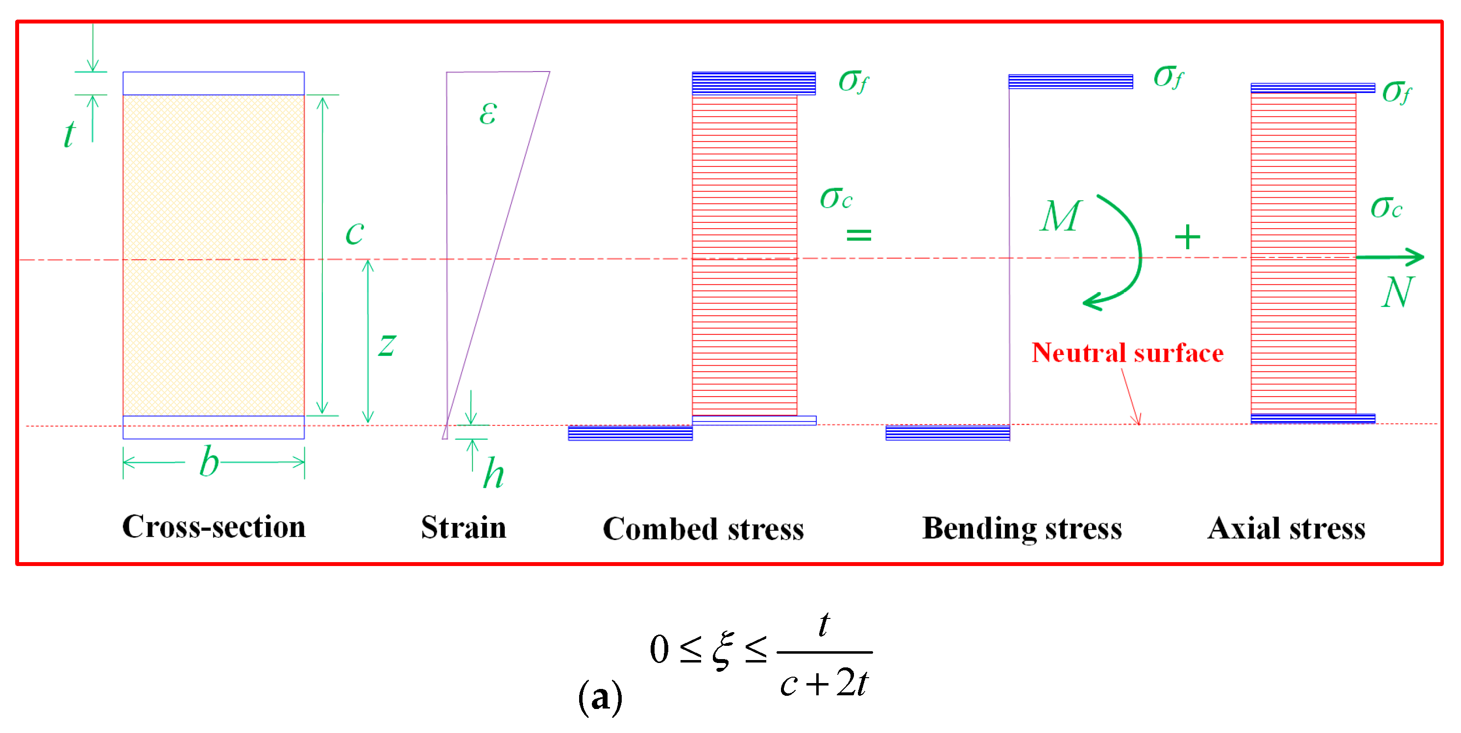
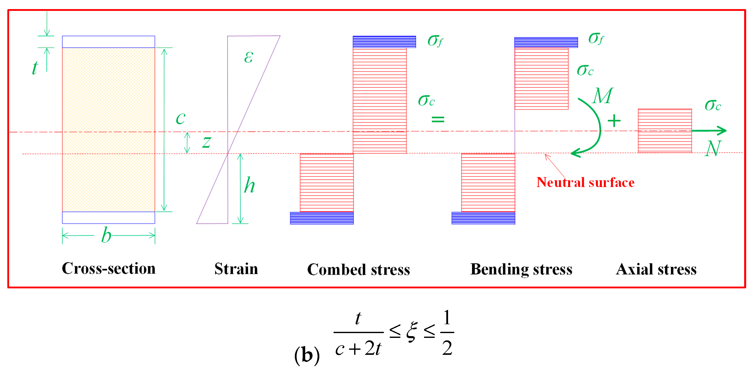
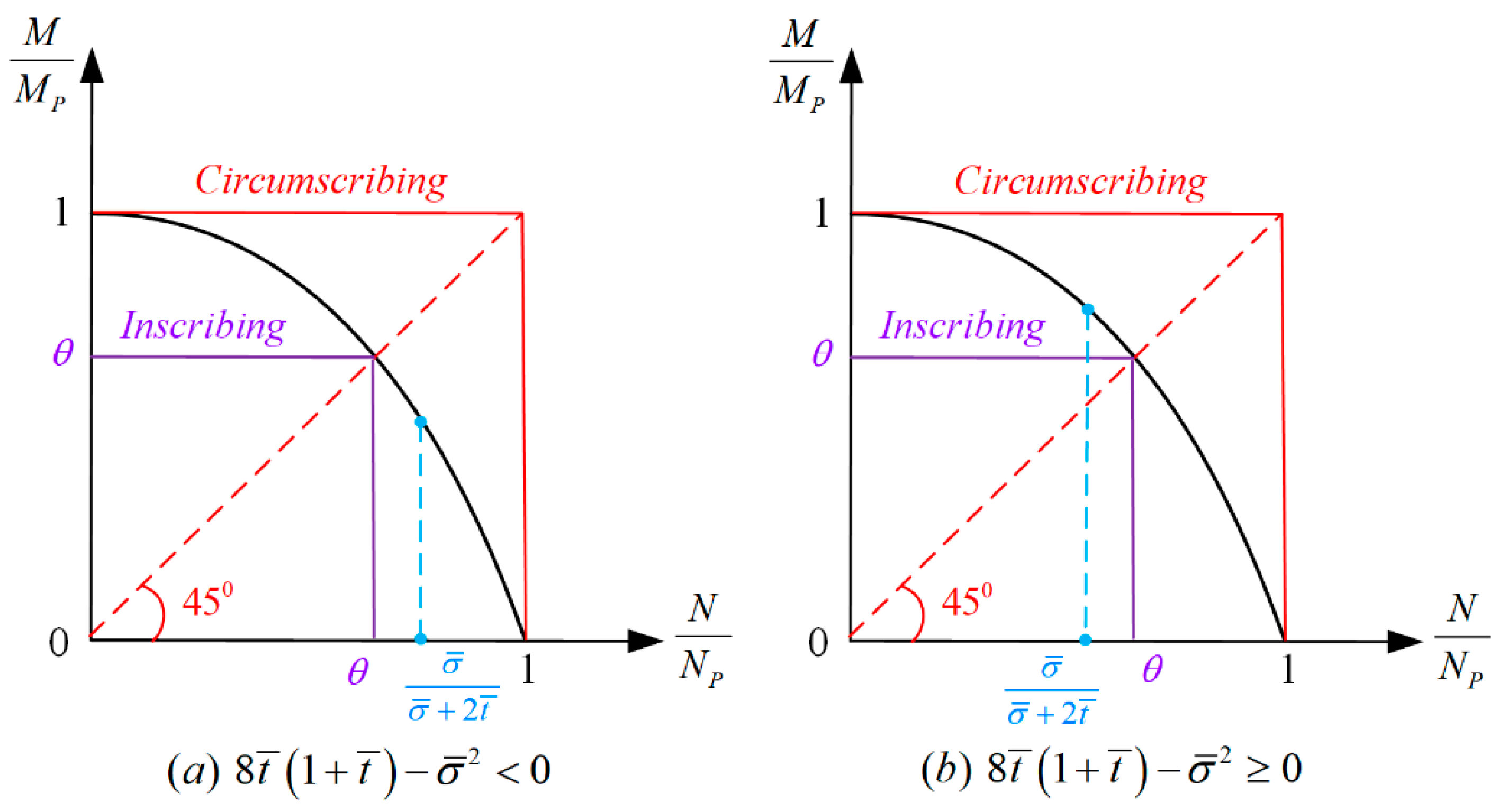
2. A Unified Yield Criterion for Sandwich Structures

When suffering from external loadings, the structures may appear deformed, including bending and axial tension. Therefore, when establishing the yield criteria, the interaction between the bending moment and the membrane force should be taken into account [32]. As for the sandwich beam, it is composed of three parts, including the front and back face sheets and the core layer, and its stress state is much more complex than that of the single-layer beam. According to the superposition principle of force, the complex stress state of a sandwich beam can be decomposed into pure bending and uniaxial tension. When the position of the neutral axis is different, the corresponding force state and direction are different.
It can be observed in reference [30] that, when MFSBs are subjected to repeated impacts, there is no delamination between the face sheets and the metal foam core. Thus, it is assumed that the face sheets are perfectly bonded to the core, and the face sheets and metal foam core obey the perfectly rigid plastic law. Meanwhile, the shear force is negligible compared to the bending moment and the axial force. Therefore, the slip interaction between the three layers is neglected in the theoretical model.
It is assumed that the thickness of the front and back face sheets is t, the thickness of the metal core is c, the width of the MFSB is b, and the distance from the bottom of the back face to the neutral axis is h. The yield strength of the face sheet and the metal foam is assumed to be σ f and σ c , respectively. Meanwhile, the moment and axial force of the MFSB are defined as M and N, respectively, and the plastic yield moment and plastic yield axial force are MP and NP. It is assumed that ξ = h / ( c + 2 t ) is a dimensionless distance from the neutral axis; then, the stress state of the MFSB can be divided into two forms according to the position of the neutral axis, as shown in Figure 2.
If 0 ξ t c + 2 t ,
N = σ c b c + 2 σ f b t ξ ( c + 2 t )
M = σ f b c + 2 t 1 2 ξ
Otherwise, if t c + 2 t ξ 1 2 ,
N = b σ c ( c + 2 t ) 1 2 ξ
M = b 4 σ c c 2 ( c + 2 t ) 2 ( 1 2 ξ ) 2 + σ f ( c + 2 t ) 2 c 2
The plastic yield moment and plastic yield axial force can be expressed as
N P = b c σ c + 2 b t σ f
M P = b 4 c 2 σ c + b t c + t σ f
Dimensionless parameters can be introduced, i.e., σ ¯ = σ c / σ f , t ¯ = t / c . Then, combining Equations (5) and (6), we can obtain
N P c M P = 4 σ ¯ + 2 t ¯ σ ¯ + 4 t ¯ ( 1 + t ¯ )
It can be derived from Equations (1)–(7):
N N P = σ ¯ + 2 t ¯ ξ ( 1 + 2 t ¯ ) σ ¯ + 2 t ¯ 0 ξ t c + 2 t σ ¯ ( 1 + 2 t ¯ ) ( 1 2 ξ ) σ ¯ + 2 t ¯ t c + 2 t ξ 1 2
M M P = 4 ( 1 + 2 t ¯ ) 2 1 ξ ξ σ ¯ + 2 t ¯ 0 ξ t c + 2 t 1 ( 1 + 2 t ¯ ) 2 ( 1 2 ξ ) 2 σ ¯ + 4 t ¯ ( 1 + t ¯ ) σ ¯ t c + 2 t ξ 1 2
Introduce dimensionless moment and axial force, i.e., m = M / M P and n = N / N P .
If 0 ξ t c + 2 t , i.e., σ ¯ σ ¯ + 2 t ¯ n 1 , then ξ = 1 n σ ¯ + 2 t ¯ 2 1 + 2 t ¯ , substitute it into Equations (8) and (9):
m + σ ¯ + 2 t ¯ n + 2 t σ + 2 n 1 σ ¯ + 2 t ¯ σ ¯ + 4 t ¯ ( 1 + t ¯ ) = 0
Otherwise, if t c + 2 t ξ 1 , i.e., 0 n σ ¯ σ ¯ + 2 t ¯ , then ξ = 1 2 1 n σ ¯ + 2 t ¯ σ ¯ 1 + 2 t ¯ , substitute it into Equations (8) and (9):
m + σ ¯ + 2 t ¯ 2 σ ¯ 2 + 4 σ ¯ t ¯ ( 1 + t ¯ ) n 2 = 1
Combine Equations (10) and (11), and the yield criterion [20] can be obtained:
m + σ ¯ + 2 t ¯ 2 σ ¯ 2 + 4 σ ¯ t ¯ ( 1 + t ¯ ) n 2 = 1 0 n σ ¯ σ ¯ + 2 t ¯ m + σ ¯ + 2 t ¯ n + 2 t σ + 2 n 1 σ ¯ + 2 t ¯ σ ¯ + 4 t ¯ ( 1 + t ¯ ) = 0 σ ¯ σ ¯ + 2 t ¯ n 1
When the sandwich beam reduces to a solid beam, namely, σ ¯ = 1 , t ¯ = 0 , then Equation (12) can be rewritten as m + n 2 = 1   , which is the same as the yield criterion of the solid beam. The yield surface of metal foam sandwich structures is illustrated in Figure 3.

3. Analytical Solutions

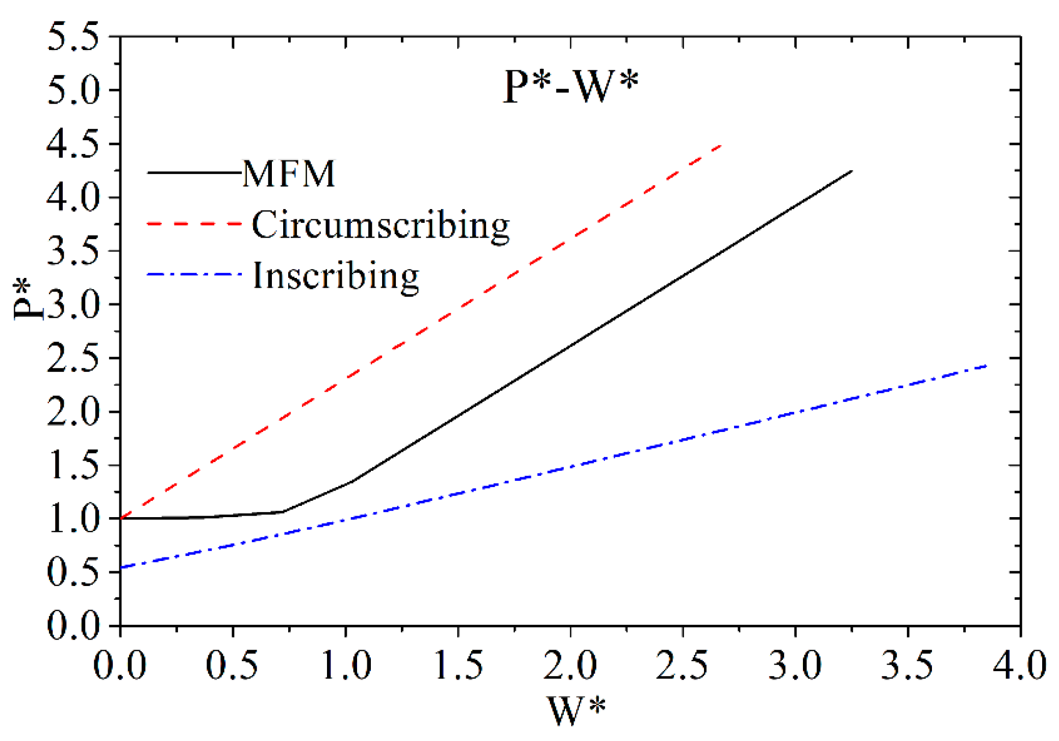
3.1. Solutions Based on the Membrane Factor Method

In order to obtain much more accurate solutions and reduce the difficulty to solve the equation, the membrane factor method (MFM) was proposed and developed by Yu and Strong [33,34,35] based on maximal normal stress yield criteria. In this method, the effects of the bending moment and the axial force were both considered, and the axial force was connected with the bending moment by the membrane factor. Thus, in this paper, the MFM will be employed and developed to analyze the dynamic responses of MFSBs suffering from repeated wedge mass impacts.
As shown in Figure 4, the MFSB is subjected to a low-velocity impact from a rigid wedge striker. The length of the beam is 2L, the width is b, and the thickness of the metal foam core is c. The mass of the wedge impactor is Gs, and the initial impact velocity is V0.
According to associated flow rules, it can be expressed as
ε ˙ κ ˙ = M P N P d m d n
(i) If 0 n σ ¯ σ ¯ + 2 t ¯ , we obtain
ε ˙ κ ˙ = M P N P σ ¯ + 2 t ¯ 2 4 σ ¯ t ¯ ( 1 + t ¯ ) + σ 2 2 n = σ ¯ + 2 t ¯ 2 σ ¯ n c
(ii) Otherwise, if σ ¯ σ ¯ + 2 t ¯ n 1 , we have
ε ˙ κ ˙ = M P N P σ ¯ + 2 t ¯ 2 n σ ¯ + 2 t ¯ + 2 2 σ ¯ 4 σ ¯ t ¯ ( 1 + t ¯ ) + σ 2 = n ( σ ¯ + 2 t ¯ ) + 1 σ ¯ 2 c
As for a fully clamped MFSB, based on the results of the repeated-impact tests conducted by Guo [30], it can be assumed that the displacement of the sandwich beam is almost linearly distributed, as displayed in Figure 5.
From the geometrical compatibility equation, we obtain
ε ˙ κ ˙ = W 0 2
Combining Equations (14)–(16), the dimensionless deflection can be given by
W = W 0 c + 2 t = σ ¯ + 2 t ¯ σ ¯ ( 1 + 2 t ¯ ) n ( 0 n σ ¯ σ ¯ + 2 t ¯ ) ( σ ¯ + 2 t ¯ ) n σ ¯ + 1 1 + 2 t ¯ ( σ ¯ σ ¯ + 2 t ¯ n 1 )
Taking the interaction between the moment and the axial force, the energy dissipation of the MFSB can be expressed as follows:
J m n = M P κ ˙ ( m + n N P M P ε ˙ κ ˙ )
When only the moment is considered, the energy dissipation of the MFSB can be written as follows:
J m = M P κ ˙
From Equations (18) and (19), the membrane force factor fn [34] can be obtained:
f n = J m n J m = m + n N P M P W 2
Due to the sandwich beam being symmetrical, half the beam can be taken as an example to perform a force analysis, as presented in Figure 6.
The moment equilibrium equation of the MFSB is
2 M + N W 0 P 2 L = 0
It can be reduced to
P = 4 M 0 L m + n N 0 M 0 W 0 2
The initial static collapse load is assumed to be
P i = 4 M 0 L
Then, the dimensionless reaction force can be expressed as
P = P P i = m + n N 0 M 0 W 0 2
Then, from Equations (20) and (24), the dimensionless reaction force can be reduced to
P = f n
Combine Equations (5), (6) and (20) and we have
f n = m + 2 σ ¯ + 2 t ¯ ( 1 + 2 t ¯ ) σ ¯ + 4 t ¯ ( 1 + t ¯ ) n W
(i) If 0 n σ ¯ σ ¯ + 2 t ¯ , then 0 W 1 1 + 2 t ¯
From Equation (17), we obtain
n = σ ¯ ( 1 + 2 t ¯ ) σ ¯ + 2 t ¯ W
Substitute Equation (27) into Equation (12) and we have
m = 1 - σ ¯ ( 1 + 2 t ¯ ) 2 4 t ¯ ( 1 + t ¯ ) + σ ¯ W 2
Substitute Equations (27) and (28) into Equation (26), and the membrane force factor can be expressed as
f n = 1 + σ ¯ ( 1 + 2 t ¯ ) 2 σ ¯ + 4 t ¯ ( 1 + t ¯ ) W 2
(ii) If σ ¯ σ ¯ + 2 t ¯ n 1 , then 1 1 + 2 t ¯ W 1
According to Equation (17), we obtain
n = ( 1 + 2 t ¯ ) W + σ ¯ 1 σ ¯ + 2 t ¯
Substitute the above equation into Equation (26) and we have
m = ( 1 + 2 t ¯ ) 2 4 t ¯ ( 1 + t ¯ ) + σ ¯ ( 1 W 2 )
Substitute Equations (30) and (31) into Equation (26), and the membrane force factor can be rewritten as
f n = ( 1 + 2 t ¯ ) ( 1 + 2 t ¯ ) ( W 2 + 1 ) + 2 ( σ ¯ 1 ) W σ ¯ + 4 t ¯ ( 1 + t ¯ )
(iii) If the deflection of the beam increases to a specific value, the beam will become like a string, which only suffers from axial force. At this moment, n = 1, m = 0, W 1 , and from Equation (26), we have
f n = 2 σ ¯ + 2 t ¯ ( 1 + 2 t ¯ ) σ ¯ + 4 t ¯ ( 1 + t ¯ ) W
Combine Equations (29), (32) and (33), and the membrane force factor can be expressed as
f n = 1 + σ ¯ ( 1 + 2 t ¯ ) 2 σ ¯ + 4 t ¯ ( 1 + t ¯ ) W 2 0 W 1 1 + 2 t ¯ ( 1 + 2 t ¯ ) ( 1 + 2 t ¯ ) ( W 2 + 1 ) + 2 ( σ ¯ 1 ) W σ ¯ + 4 t ¯ ( 1 + t ¯ ) 1 1 + 2 t ¯ W 1 2 σ ¯ + 2 t ¯ ( 1 + 2 t ¯ ) σ ¯ + 4 t ¯ ( 1 + t ¯ ) W W 1
If only the moment works, the energy dissipation of the MFSB can be given by
D m = 0 θ 4 M P d θ = 0 W 0 4 M P L ( c + 2 t ) d W
However, when both the moment and the axial force are considered, the energy dissipation of the MFSB can be written as
D m n = 0 θ 4 M P f n d θ = 0 W 0 4 M P L ( c + 2 t ) f n d W = 4 M P c ¯ ( 1 + 2 t ¯ ) 0 W 0 f n d W
Assuming that the mass of impactor is Gs and the initial impact velocity is V0, then the initial impact energy is
E K = 1 2 G s V 0 2
Define dimensionless kinetic energy and plastic energy as
E K = E K 4 M P c ¯ ( 1 + 2 t ¯ )
D m n = D m n 4 M P c ¯ ( 1 + 2 t ¯ )
Combine Equations (36)–(38) and we have
D m n = σ ¯ ( 1 + 2 t ¯ ) 2 3 σ ¯ + 4 t ¯ ( 1 + t ¯ ) W 0 3 + W 0   ,   0 W 1 1 + 2 t ¯ ( 1 + 2 t ¯ ) 2 3 σ ¯ + 4 t ¯ ( 1 + t ¯ ) W 0 3 + ( 1 + 2 t ¯ ) ( σ ¯ 1 ) σ ¯ + 4 t ¯ ( 1 + t ¯ ) W 0 2 + ( 1 + 2 t ¯ ) 2 σ ¯ + 4 t ¯ ( 1 + t ¯ ) W 0 + σ ¯ 1 3 σ ¯ + 4 t ¯ ( 1 + t ¯ ) 1 + 2 t ¯   ,   1 1 + 2 t ¯ W 1 ( 1 + 2 t ¯ ) ( σ ¯ + 2 t ¯ ) σ ¯ + 4 t ¯ ( 1 + t ¯ ) W 0 2 1 + 4 ( 1 + 2 t ¯ ) 3 + 4 ( 3 t ¯ 2 + 3 t ¯ + 1 ) ( σ ¯ 1 ) 3 σ ¯ + 4 t ¯ ( 1 + t ¯ ) 1 + 2 t ¯   ,   W 1
Define W 0 = δ , and introduce a, b, c, and d as coefficients of δ, namely
a 1 = σ ¯ ( 1 + 2 t ¯ ) 2 3 σ ¯ + 4 t ¯ ( 1 + t ¯ ) , a 2 = ( 1 + 2 t ¯ ) 2 3 σ ¯ + 4 t ¯ ( 1 + t ¯ ) , a 3 = ( 1 + 2 t ¯ ) ( σ ¯ + 2 t ¯ ) σ ¯ + 4 t ¯ ( 1 + t ¯ )
b 2 = ( 1 + 2 t ¯ ) ( σ ¯ 1 ) σ ¯ + 4 t ¯ ( 1 + t ¯ ) , c 2 = ( 1 + 2 t ¯ ) 2 σ ¯ + 4 t ¯ ( 1 + t ¯ )
d 2 = σ ¯ 1 3 σ ¯ + 4 t ¯ ( 1 + t ¯ ) 1 + 2 t ¯   , d 3 = 4 ( 1 + 2 t ¯ ) 3 + 4 ( 3 t ¯ 2 + 3 t ¯ + 1 ) ( σ ¯ 1 ) 3 σ ¯ + 4 t ¯ ( 1 + t ¯ ) 1 + 2 t ¯ ( 1 + 2 t ¯ ) ( σ ¯ + 2 t ¯ ) σ ¯ + 4 t ¯ ( 1 + t ¯ )
Then, Equation (39) can be reduced to
D m n = a 1 δ 3 + δ   ,   0 δ 1 1 + 2 t ¯ a 2 δ 3 + b 2 δ 2 + c 2 δ + d 2   ,   1 1 + 2 t ¯ δ 1 b 3 δ 2 + d 3   ,   δ 1
Assume the impact number is i; then, according to the energy conservation theorem, we have
a 1 δ i 3 + δ i = 0 i E K n   ,   0 δ i 1 1 + 2 t ¯ a 2 δ i 3 + b 2 δ i 2 + c 2 δ i + d 2 = 0 i E K n   ,   1 1 + 2 t ¯ δ i 1 1 a 3 δ i 2 + d 3 = 0 i E K n   ,   δ i 1
The analytical expression of permanent deflection of MFSBs in the ith impact number can be obtained from Equation (41), as follows:
(1) If 0 δ i 1 1 + 2 t ¯
Assume that
p 1 = 1 a 1 = 3 σ ¯ + 4 t ¯ ( 1 + t ¯ ) σ ¯ ( 1 + 2 t ¯ ) 2 q 1 = i E K 0 a 1 = 3 σ ¯ + 4 t ¯ ( 1 + t ¯ ) σ ¯ ( 1 + 2 t ¯ ) 2 0 i E K n
Equation (41) can be reduced
δ i 3 + p 1 δ i + q 1 = 0
Define
Δ 1 = q 1 2 4 + p 1 3 27
Then, the expression of a dimensionless deflection can be given as
δ i = q 1 2 + Δ 1 3 + q 1 2 + Δ 1 3
(2) If 1 1 + 2 t ¯ δ i 1 1
Define
φ = δ i + b 2 3 a 2 p 2 = 3 a 2 c 2 b 2 2 3 a 2 2 q 2 = 2 b 2 3 9 a 2 b 2 c 2 + 27 a 2 2 d 2 27 a 2 3 d 2 = d 2 0 i E K n
Then, we have
φ 3 + p 2 φ + q 2 = 0
Δ 2 = q 2 2 4 + p 2 3 27
φ = q 2 2 + Δ 2 3 + q 2 2 + Δ 2 3
Then, we can obtain the following:
δ i = q 2 2 + Δ 2 3 + q 2 2 + Δ 2 3 b 2 3 a 2
(3) If δ i 1
δ i 2 + d 3 a 3 1 a 3 0 i E K n = 0
δ i = 0 i E K n d 3 b 3

3.2. Solutions Based on Square Yield Surface

Similar to solid structures, the square yield surface can be employed to solve the plastic responses of sandwich beams subjected to repeated-impact loadings, and the corresponding bounds of solutions can be obtained.
As for circumscribing yield surface, m = n = 1 , i.e., M = M P , N = N P
On the other hand, for inscribing yield surface, it is assumed that N = θ N P and M = θ M P , namely,
m = n = θ
(i) If θ σ ¯ σ ¯ + 2 t ¯
Substituting Equation (53) into Equation (12), we obtain
θ + σ ¯ + 2 t ¯ 2 4 σ ¯ t ¯ ( 1 + t ¯ ) + σ ¯ 2 θ 2 = 1
Assume k 0 = σ ¯ + 2 t ¯ 2 4 σ ¯ t ¯ ( 1 + t ¯ ) + σ ¯ 2
Then, Equation (54) can be reduced to
θ = 1 + 4 k 0 1 2 k 0
Meanwhile, θ σ ¯ σ ¯ + 2 t ¯ ; then, from Equation (55), we obtain
8 t ¯ 1 + t ¯ σ ¯ 2 0
(ii) If θ σ ¯ σ ¯ + 2 t ¯
Substitute Equation (53) into Equation (12) and we obtain
θ 2 + 1 σ ¯ 3 σ ¯ + 8 t ¯ σ ¯ + 2 t ¯ 2 + 1 θ 2 ( 1 σ ¯ ) σ ¯ + 2 t ¯ + 1 = 0
Assume k 1 = 1 σ ¯ 3 σ ¯ + 8 t ¯ σ ¯ + 2 t ¯ 2 + 1 , k 2 = 2 ( 1 σ ¯ ) σ ¯ + 2 t ¯ + 1
Then, Equation (57) can be reduced to
θ = k 1 2 + 4 k 2 k 1 2
And we obtain
8 t ¯ 1 + t ¯ σ ¯ 2 0
Then, the square yield surface of sandwich structures can be obtained, as presented in Figure 7.
For a fully clamped sandwich beam, when only the plastic yield moment works, the plastic energy dissipation rate can be expressed as
D ˙ m = 4 M P θ m
While both the moment and the axial force are considered for the plastic energy dissipation, the energy dissipation rate can be written as
D ˙ m n = 4 M P 1 + N P M P W 2 θ m
Integrate the above equation and we can obtain
D m n = 0 θ m 4 M P 1 + N P M P W 2 θ m d θ = 0 W 4 M P c ¯ ( 1 + 2 t ¯ ) 1 + N P M P W 2 d W
Based on energy conservation Dmn = EK0, we obtain
E K 0 * = ( σ ¯ + 2 t ¯ ) ( 1 + 2 t ¯ ) σ ¯ + 4 t ¯ ( 1 + t ¯ ) W * 2 + W *
Solve Equation (63), and the dimensionless deflection of the MFSB based on circumscribing the yield surface can be derived as
W 0 c = σ ¯ + 4 t ¯ ( 1 + t ¯ ) 2 ( σ ¯ + 2 t ¯ ) ( 1 + 2 t ¯ ) 1 + 4 ( σ ¯ + 2 t ¯ ) ( 1 + 2 t ¯ ) σ ¯ + 4 t ¯ ( 1 + t ¯ ) E K 0 1
Similarly, the dimensionless deflection of the MFSB based on inscribing yield surface can be given as
W 0 i = σ ¯ + 4 t ¯ ( 1 + t ¯ ) 2 ( σ ¯ + 2 t ¯ ) ( 1 + 2 t ¯ ) 1 + 4 ( σ ¯ + 2 t ¯ ) ( 1 + 2 t ¯ ) σ ¯ + 4 t ¯ ( 1 + t ¯ ) E K 0 θ 1
As for repeated impacts, employing the principle of energy and deformation accumulation, the dimensionless deflection for the ith impact can be derived as follows:
W 0 c i = σ ¯ + 4 t ¯ ( 1 + t ¯ ) 2 ( σ ¯ + 2 t ¯ ) ( 1 + 2 t ¯ ) 1 + 4 ( σ ¯ + 2 t ¯ ) ( 1 + 2 t ¯ ) σ ¯ + 4 t ¯ ( 1 + t ¯ ) i E K 0 1
W 0 i i = σ ¯ + 4 t ¯ ( 1 + t ¯ ) 2 ( σ ¯ + 2 t ¯ ) ( 1 + 2 t ¯ ) 1 + 4 ( σ ¯ + 2 t ¯ ) ( 1 + 2 t ¯ ) σ ¯ + 4 t ¯ ( 1 + t ¯ ) i E K 0 θ 1

4. Results and Discussion

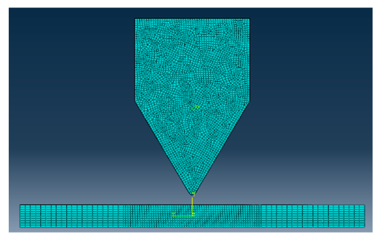
4.1. Validation of Theoretical Model

In order to verify the accuracy of the theoretical model, the permanent deflections predicted by the theoretical method are compared with those of repeated-impact tests [30] and numerical simulations [31].
The metal foam sandwich beam was composed of a front face sheet, a back face sheet, and an aluminum foam core. Epoxy resin was used to glue the face sheets and the core. The material of the face sheets was mild steel, and the core material was closed-cell aluminum foam with a density of 0.5 g/cm3. The thicknesses of the face sheets and the core were t = 1 mm and c = 10 mm, respectively. The total length and the span length of the MFSB were LB = 250 mm and LS = 150 mm, respectively, and the width of the beam was B = 30 mm. The impactor mass was 7.884 kg, and the impact velocity was 2.12 m/s, i.e., the impact energy was 17.8 J. The apparatus used for repeated-impact tests is presented in Figure 8.
Dynamic responses of MFSBs obtained from repeated-impact tests are illustrated in Table 1, comprising permanent deflections, rebound energy, and absorbed energy.
The numerical model is created by ABAQUS. In the numerical model, the length of the sandwich beam is 150 mm, the width of the beam is 30 mm, and the thickness of the core and the face sheet is 10 mm and 1 mm, respectively. The width of the wedge impactor is 40 mm, the included angle of the wedge is 60°, and the fillet radius is 1.5 mm. In the numerical model, the face sheet is specified as an elastic/plastic material, and the elastic part is defined by the following parameters: Young’s modulus and Poisson’s ratio, and the hardening behavior is defined using the true plastic stress–strain curve. As for the metal foam core, the material model is defined as crushable foam. As for aluminum foam, the elastic and plastic Poisson’s ratios are 0.3 and 0, respectively, and the plastic stress ratio is 1.73. The plastic stress–strain curves of mild steel and aluminum foam obtained from material tests are presented in Figure 9.
As for the mesh, the width of the refined area is 60 mm, and the mesh sizes of refined and non-refined areas are 1 mm and 2.5 mm, respectively. The mesh sizes of the beam along the direction of thickness and width are 1 mm and 1.5 mm, respectively. The mesh convergence was analyzed in our previous study [31], and the mesh size for face sheets and foam core in the present numerical model was satisfied with convergence requirements. The wedge impactor is defined as a discrete rigid body, and a quadrilateral shell element (R3D4) is chosen. Meanwhile, a core layer and face sheets adopt linear reduction integral hexahedral element (C3DR8) and quadrilateral shell element (S4R), respectively. The finite-element model of numerical simulations is illustrated in Figure 10.
The rebound effect of the MFSB is considered to be a form of the energy-absorption coefficient obtained from impact tests. Ek and Eir are defined as initial impact energy and rebound energy, respectively. Meanwhile, V0 and Vir are defined as initial impact velocity and rebound velocity, respectively. When considering the influence of rebound of the impactor, the elastic energy should be subtracted from the total energy, that is, the plastic dissipation energy of the MFSB can be expressed as
D m n = 1 i E K E i r = 1 i 1 2 m V 0 2 V i r 2
The relationship between absorbed energy and the impact number (N) can be obtained from repeated-impact tests [30], as presented in Table 1. Meanwhile, the expression of the energy-absorption coefficient in the form of an impact number (N) can be obtained, as illustrated in Equation (69).
E K E i r E K = 0.997 0.014 N
As for mild steel, the yield stress in the theoretical model is assumed to be the average value between the initial yield stress and the ultimate strength, as follows:
σ f = σ y + σ u 2
For the metal foam core, the yield stress can be assumed to be equal to plateau stress, i.e.,
σ c = σ p
In the theoretical model, the material properties and geometric parameters are the same as in the impact tests. Meanwhile, the boundary condition, impact mass, and impact velocity also stay the same as in the impact tests. In the repeated-impact tests, the impact mass is 7.884 kg, the impact velocity is 2.12 m/s, and the impact energy is 17.8 J. The geometric parameters and material properties as well as the dimensionless parameters of the MFSB are presented in Table 2.
The correlation curves between dimensionless deflections with the impact number obtained from the membrane factor method, the square yield surface, the repeated-impact tests, and numerical simulations are illustrated in Table 3 and Figure 11. It can be observed that the dimensionless deflections predicted by the membrane factor method are very close to those of the impact tests and numerical simulations, and the discrepancies between the above three different methods are very small, which all lie between the results of inscribing and circumscribing yield surface. When the impact number is small, the differences in dimensionless deflections between different methods are relatively small. As the impact number increases, however, the discrepancy between dimensionless deflections obtained by the membrane force method, the square yield surface, repeated-impact tests, and numerical simulations increase gradually.
Some assumptions have been made in the theoretical model, resulting in differences between the results of the theoretical analysis and those of the impact tests. On the one hand, the influence of friction has not been considered in the theoretical model, which would consume energy in the impact tests. On the other hand, in the theoretical model, the yield stress of the face sheet is assumed to be the average value of the initial yield stress and ultimate stress. While in the impact tests, the yield stress of the face sheet would change as the strain increases. Thus, when the deflection is small, the yield stress of the theoretical model would be larger than impact tests, but it would be smaller when the deflection is larger. Therefore, when the impact number is small, the permanent deflections obtained by the membrane factor method are smaller than those of impact tests and numerical simulations. By contrast, when the impact number is larger, the permanent deflections predicted by the membrane factor method are larger than those of impact tests and numerical simulations. The deformation profiles of the MFSB for the first, fifth, and tenth impact are presented in Figure 12. The deformation profiles obtained from MFM lie between those of circumscribing yield surface and inscribing yield surface, which are very close to those of impact tests and numerical simulations.
Based on the above comparisons and analyses, it is confirmed that the predictions of the membrane factor method agree well with those of the corresponding impact tests and numerical simulations, indicating that the theoretical method proposed in this paper has high accuracy in analyzing the plastic responses of MFSBs suffering from repeated impacts.

4.2. Dynamic Responses of MFSBs

The correlation between dimensionless permanent deflections and the impact number is shown in Figure 13. As the impact number increases, the dimensionless deflection increases gradually, while the increment decreases. Meanwhile, the deflections derived from the MFM are between the upper and lower solutions obtained by the method based on the square yield surface. When a deflection is smaller than the total thickness of the sandwich beam ( W * 1 ), both the moment and the membrane force work and consume energy. Therefore, the results obtained by the MFM are much closer to those of the inscribing yield surface. When deflection exceeds the total thickness of the sandwich beams ( W * > 1 ), the sandwich beams are in the membrane state and behave like a stretched plastic sting, and only the membrane force works. Thus, the impact number increases, and the results obtained by the MFM become much closer to those of circumscribing yield surface. The correlation between the dimensionless impact force and the impact number is shown in Figure 14. The dimensionless impact force predicted by the membrane factor method is between the upper and lower solutions based on the square yield surface. The initial collapse force solved by the membrane factor method is equal to that of the method based on circumscribing the yield surface. With the increase in the impact number, the dimensionless impact force predicted by the membrane factor method approaches the result obtained by the circumscribing yield surface.
The correlations between the dimensionless impact force and dimensionless deflection are presented in Figure 15. As for the results obtained from the square yield surface, the dimensionless impact force increases linearly with the increase in dimensionless deflection. Meanwhile, the results derived from the MFM lie between those of the inscribing and circumscribing yield surface. When W * 1 , the slopes of the membrane factor method solutions are equal to those of the square yield surface solutions. The correlation between dimensionless deflection and dimensionless impact energy is displayed in Figure 16. The results obtained from the MFM are between the solutions of the upper and lower yield surfaces, and as impact energy increases, the results of the MFM become closer to those of the circumscribing yield surface.
Through the above analysis, it can be seen that the results of the membrane factor method are within the upper and lower limits obtained by the square yield. When the impact number is small, the deflection obtained by the membrane factor method is close to the result of the inscribing yield surface solution. However, when the impact number is large, the deflection value obtained by the membrane factor method is close to the result of the circumscribing yield surface solution.

4.3. Effect of Core Strength

The core strength ratio (CSR) is defined as variation that can be used to study the effect of core strength on the dynamic responses of MFSBs, and seven cases are selected, as illustrated in Table 4, namely, CSR-0.01, CSR-0.05, CSR-0.1, CSR-0.2, CSR-0.3, CSR-0.5, and CSR-1. Most of the geometric parameters and energy parameters remain the same, as listed in Table 1, and only some parameters related to core yield strength are changed accordingly.
The effect of core strength on the dynamic responses of MFSBs is shown in Figure 15. Core strength has a significant effect on the permanent deflections of MFSBs. It can be seen from Figure 17a, as for different CSRs, that the trends of the W*-N curves are almost the same, i.e., W* increases gradually with the increasing impact number while the increment slope decreases. As the impact number increases, the total energy absorbed by the MFSB increases, and the deformation of the MFSB accumulates gradually, resulting in the effect of the core strength ratio becoming more significant with the increase in impact number. The relationship between dimensionless deflection and core strength ratio is presented in Figure 17b. It can be seen, both for different impact numbers, that the dimensionless permanent deflection decreases with the increase in the core strength ratio in exponential form. Meanwhile, the core strength ratio is smaller, and the effect on dimensionless deflection is much more significant. When the geometric parameters and impact energy as well as face strength remain unchanged, if the core strength ratio increases, both MP and NP increase, meaning the load-carrying capacity of the MFSB improves, resulting in a decrease in the dimensionless permanent deflection with the increase in the core strength ratio.
In conclusion, the dimensionless permanent deflection of the MFSB is sensitive to the core strength ratio, and as the impact number increases, the dimensionless permanent deflection decreases gradually. Meanwhile, the influence of core strength becomes more significant as the impact number increases.

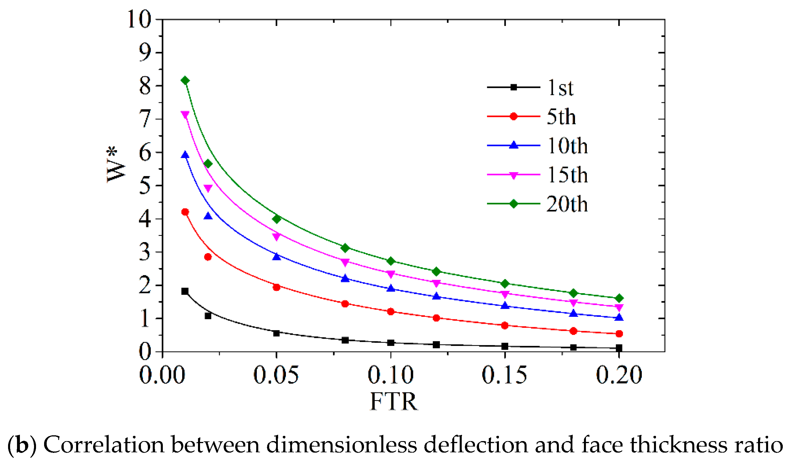
4.4. Effect of Face Thickness

In order to determine the effect of face thickness on the dynamic responses of MFSB, nine cases are selected, as illustrated in Table 5, and the face thickness ratio (FTR) is defined as the variation. Most of the geometric parameters and energy parameters remain the same as those listed in Table 1; only some parameters related to face thickness are changed accordingly.
The effect of the face thickness ratio on the dynamic responses of the MFSB is shown in Figure 16. From Figure 18a, it can be observed that the dimensionless permanent deflection increases with impact number, while the increment decreases, and for different cases, the trends are very similar. Meanwhile, discrepancies between each case grow as the impact number increases. The correlation between dimensionless deflection and the face thickness ratio is displayed in Figure 18b. As the face thickness ratio increases, the dimensionless permanent deflection decreases gradually in exponential form. Meanwhile, when the face thickness ratio becomes smaller, the effect of face thickness becomes more significant. When the face thickness increases, the load-carrying capacity of the MFSB increases; thus, once subjected to identical impact energy, the permanent deflection decreases.

5. Conclusions

In this paper, a theoretical model based on a perfect rigid-plasticity assumption is established, and the membrane factor method is employed to derive the dynamic plastic responses of MFSBs under repeated mass impact. Meanwhile, the rebound effect of MFSBs is taken into account based on the results of impact tests. In addition, the yield criterion based on the square yield surface is employed to obtain upper and lower bounds for plastic responses. In addition, the results obtained from the membrane factor method are compared with those from impact tests and numerical simulations to verify the accuracy of the proposed theoretical model. In addition, the effects of core strength ratio and face thickness ratio on the deflection responses of MFSBs are analyzed based on the MFM. Thus, the following conclusions can be drawn:
(1) The dimensionless permanent deflections derived from the membrane factor method agree well with those of repeated-impact tests and numerical simulations, indicating that the proposed method is of high accuracy for predicting the plastic responses of MFSBs suffering from repeated impacts.
(2) The process of solving the equation based on the square yield surface is much simpler, but the result of the membrane factor method is more accurate, which is within the bound solution range of the square yield surface.
(3) The dimensionless permanent deflection of MFSBs is sensitive to the core strength ratio, and as the core strength ratio increases, the dimensionless permanent deflection decreases gradually in exponential form. Meanwhile, the influence of core strength becomes more significant as the impact number increases.
(4) The face thickness ratio has a visible effect on the dimensionless permanent deflection of MFSBs, which is more significant in the case of small face thickness ratios. As the face thickness ratio increases, the dimensionless permanent deflection decreases gradually in exponential form. Meanwhile, the influence of the face thickness ratio becomes more significant as the impact number increases.
Though the proposed theoretical method based on the MFM can predict the plastic responses of MFSBs subjected to repeated impacts with high accuracy, the corresponding theoretical model for metal foam sandwich plates (MFSPs) has not been established due to the complex structural forms and force states of the MFSPs. Thus, future investigations must establish the theoretical model of MFSPs suffering from repeated impacts and employ the MFM to obtain accurate solutions for plastic responses.

Author Contributions

Conceptualization, K.G.; methodology, L.Z.; formal analysis and investigation, B.X. and M.M.; writing—original draft preparation, K.G.; writing—review and editing, W.C. All authors have read and agreed to the published version of the manuscript.

Funding

This work was financially supported by the project of National Natural Science Foundation of China (Grant number: 12202328, 12172265), and the project of Key Laboratory of Impact and Safety Engineering (Ningbo University), Ministry of Education (Grant number: CJ202203).

Institutional Review Board Statement

Not applicable.

Informed Consent Statement

Not applicable.

Data Availability Statement

Not applicable.

Acknowledgments

The authors gratefully acknowledge the support from the project of National Natural Science Foundation of China (Grant number: 12202328, 12172265), and the project of Key Laboratory of Impact and Safety Engineering (Ningbo University), Ministry of Education (Grant number: CJ202203).

Conflicts of Interest

The authors declare no conflict of interest.

References

  1. Zhu, L.; Faulkner, D. Damage estimate for plating of ships and platforms under repeated impacts. Mar. Struct. 1996, 9, 697–720. [Google Scholar] [CrossRef]
  2. Truong, D.D.; Jung, H.J.; Shin, H.K.; Cho, S.R. Response of low-temperature steel beams subjected to single and repeated lateral impacts. Int. J. Nav. Arch. Ocean 2018, 10, 670–682. [Google Scholar] [CrossRef]
  3. Truong, D.D.; Shin, H.K.; Cho, S.R. Repeated lateral impacts on steel grillage structures at room and sub-zero temperatures. Int. J. Impact Eng. 2018, 113, 40–53. [Google Scholar] [CrossRef]
  4. Zhu, L.; Shi, S.; Jones, N. Dynamic response of stiffened plates under repeated impacts. Int. J. Impact Eng. 2018, 117, 113–122. [Google Scholar] [CrossRef]
  5. Zeng, Y.; Chen, H.; Yu, R.; Shen, Z.; Yu, Z.; Liu, J. Experimental research on dynamic behavior of circular mild steel plates with surface cracks subjected to repeated impacts in low temperature. Shock Vib. 2020, 2020, 3713709. [Google Scholar] [CrossRef]
  6. Jones, N. Pseudo-shakedown phenomenon for the mass impact loading of plating. Int. J. Impact Eng. 2014, 65, 33–39. [Google Scholar] [CrossRef]
  7. He, X.; Soares, C.G. Experimental study on the dynamic behavior of beams under repeated impacts. Int. J. Impact Eng. 2021, 147, 103724. [Google Scholar] [CrossRef]
  8. He, X.; Soares, C.G. Numerical study on the pseudo-shakedown of beams under repeated impacts. Ocean Eng. 2021, 242, 110137. [Google Scholar] [CrossRef]
  9. He, X.; Garbatov, Y.; Soares, C.G. Analysis of pseudo-shakedown of rectangular plates under repeated impacts. Ocean Eng. 2022, 265, 112609. [Google Scholar] [CrossRef]
  10. He, X.; Garbatov, Y.; Soares, C.G. Pseudo-shakedown of rectangular plates under repeated impacts. Mar. Struct. 2022, 85, 103258. [Google Scholar] [CrossRef]
  11. Cai, W.; Zhu, L.; Qian, X. Dynamic responses of steel plates under repeated ice impacts. Int. J. Impact Eng. 2022, 162, 104129. [Google Scholar] [CrossRef]
  12. Zhang, Y.; Li, Y.G.; Guo, K.L.; Zhu, L. Dynamic mechanical behaviour and energy absorption of aluminium honeycomb sandwich panels under repeated impact loads. Ocean Eng. 2021, 209, 108344. [Google Scholar] [CrossRef]
  13. Zeng, Y.; Liu, J.X.; Zhao, Y.J. Experimental research on the repeated impacts behavior of aluminium corrugated-core sandwich structures. Shock Vib. 2022, 2022, 4644029. [Google Scholar]
  14. Palomba, G.; Epasto, G.; Sutherland, L.; Crupi, V. Aluminium honeycomb sandwich as a design alternative for lightweight marine structures. Ships Offshore Struct. 2022, 17, 2355–2366. [Google Scholar] [CrossRef]
  15. Mozafari, H.; Distefano, F.; Epasto, G.; Gu, L.; Linul, E.; Crupi, V. Design of an Innovative Hybrid Sandwich Protective Device for Offshore Structures. J. Mar. Sci. Eng. 2022, 10, 1385. [Google Scholar] [CrossRef]
  16. Lin, H.; Han, C.; Yang, L.; Karampour, H.; Luan, H.; Han, P.; Xu, H.; Zhang, S. Dynamic Performance and Crashworthiness Assessment of Honeycomb Reinforced Tubular Pipe in the Jacket Platform under Ship Collision. J. Mar. Sci. Eng. 2022, 10, 1194. [Google Scholar] [CrossRef]
  17. Corigliano, P.; Palomba, G.; Crupi, V.; Garbatov, Y. Stress–Strain Assessment of Honeycomb Sandwich Panel Subjected to Uniaxial Compressive Load. J. Mar. Sci. Eng. 2023, 11, 365. [Google Scholar] [CrossRef]
  18. Guo, H.Y.; Zhang, J.X. Expansion of sandwich tubes with metal foam core under axial compression. J. Appl. Mech. 2023, 90, 051008. [Google Scholar] [CrossRef]
  19. Jing, L.; Wang, Z.; Ning, J.; Zhao, L.M. The dynamic response of sandwich beams with open-cell metal foam cores. Compos. Part B-Eng. 2011, 42, 1–10. [Google Scholar] [CrossRef]
  20. Qin, Q.H.; Wang, T.J. A theoretical analysis of the dynamic response of metallic sandwich beam under impulsive loading. Eur. J. Mech. A-Solid 2009, 28, 1014–1025. [Google Scholar] [CrossRef]
  21. Qin, Q.H.; Wang, T.J. Low-velocity heavy-mass impact response of slender metal foam core sandwich beam. Compos. Struct. 2011, 93, 1526–1537. [Google Scholar] [CrossRef]
  22. Qin, Q.H.; Wang, T.J. Plastic Analysis of Metal Foam Core Sandwich Beam Transversely Loaded by a Flat Punch: Combined Local Denting and Overall Deformation. Int. J. Appl. Mech. 2012, 79, 041010. [Google Scholar] [CrossRef]
  23. Qin, Q.H.; Wang, T.J. Low-velocity impact response of fully clamped metal foam core sandwich beam incorporating local denting effect. Compos. Struct. 2013, 96, 346–356. [Google Scholar] [CrossRef]
  24. Asemi, K.; Salami, S.J. A study on low velocity impact response of FGM rectangular plates with 3D elasticity based graded finite element modeling. J. Theor. Appl. Mech. 2015, 53, 859–872. [Google Scholar] [CrossRef]
  25. Zafarmand, H.; Salehi, M.; Asemi, K. Three dimensional free vibration and transient analysis of two directional functionally graded thick cylindrical panels under impact loading. Lat. Am. J. Solids Struct. 2015, 12, 205–225. [Google Scholar] [CrossRef]
  26. Khatounabadia, M.; Jafariaand, M.; Asemi, K. Low-velocity impact analysis of functionally graded porous circular plate reinforced with graphene platelets. Wave Random Complex Media 2022, 6, 2091182. [Google Scholar] [CrossRef]
  27. Zhang, W.; Qin, Q.H.; Li, K.; Li, J.F.; Wang, Q. Effect of stepwise gradient on dynamic failure of composite sandwich beams with metal foam core subject to low-velocity impact. Int. J. Solids Struct. 2021, 228, 111125. [Google Scholar] [CrossRef]
  28. Fang, B.; Huang, W.; Xu, H.; Jiang, C.; Liu, J. High-velocity impact resistance of stepwise gradient sandwich beams with metal foam cores. Thin Wall Struct. 2022, 181, 110054. [Google Scholar] [CrossRef]
  29. Zhou, X.F.; Jing, L. Large deflection response of sandwich beams with layered-gradient foam cores subjected to low-velocity impact. Int. J. Impact Eng. 2023, 172, 104429. [Google Scholar] [CrossRef]
  30. Guo, K.L.; Mu, M.Y.; Zhou, S. Investigation on the dynamic behaviors of aluminum foam sandwich beams subjected to repeated low-velocity impacts. Metals 2023, 13, 1115. [Google Scholar] [CrossRef]
  31. Guo, K.L.; Mu, M.Y.; Zhou, S.; Zhang, Y.J. Dynamic responses of metal foam sandwich beam under repeated impacts considering impact location and face thickness distribution. Compos. Part C-Open 2023, 11, 100372. [Google Scholar] [CrossRef]
  32. Qin, Q.H.; Wang, T.J. An analytical solution for the large deflections of a slender sandwich beam with a metallic foam core under transverse loading by a flat punch. Compos. Struct. 2009, 88, 509–518. [Google Scholar] [CrossRef]
  33. Yu, T.X.; Stronge, W.J. Large deflections of a rigid-plastic beam-on-foundation from impact. Int. J. Impact Eng. 1990, 9, 115–126. [Google Scholar] [CrossRef]
  34. Yu, T.X.; Chen, F.L. Analysis of large deflection dynamic response of rigid-plastic beams. J. Eng. Mech. 1993, 119, 1293–1301. [Google Scholar]
  35. Zhu, L.; Tian, L.R.; Chen, F.L.; Yu, T.X. A new equivalent method for complex- shaped pulse loading based on saturation analysis and membrane factor method. Int. J. Impact Eng. 2021, 158, 104018. [Google Scholar] [CrossRef]
Figure 1. Flowchart of sequence of the developed analytical model.
Jmse 11 01974 g001
Figure 2. Distribution of the strain and stress in the sandwich cross-section.
Jmse 11 01974 g002aJmse 11 01974 g002b
Figure 3. Yield surface of metal foam sandwich structures.
Jmse 11 01974 g003
Figure 4. Sketch of fully clamped sandwich beam under impact from wedge mass.
Jmse 11 01974 g004
Figure 5. Deformation pattern of the neutral axis of the fully clamped MFSB.
Jmse 11 01974 g005
Figure 6. Sketch of the force state for the fully clamped MFSB.
Jmse 11 01974 g006
Figure 7. Square yield surface of sandwich structures.
Jmse 11 01974 g007
Figure 8. Apparatus of repeated-impact test [30].
Jmse 11 01974 g008
Figure 9. Plastic stress–strain curve.
Jmse 11 01974 g009
Figure 10. Finite-element model of numerical simulations [31].
Jmse 11 01974 g010
Figure 11. Correlation curves between dimensionless deflections with impact number.
Jmse 11 01974 g011
Figure 12. Deformation profile of the MFSB for different impact numbers.
Jmse 11 01974 g012
Figure 13. Dimensionless permanent deflection vs. impact number.
Jmse 11 01974 g013
Figure 14. Dimensionless impact force vs. impact number.
Jmse 11 01974 g014
Figure 15. Dimensionless impact force vs. deflection.
Jmse 11 01974 g015
Figure 16. Dimensionless deflection vs. impact energy.
Jmse 11 01974 g016
Figure 17. Effect of core strength on dynamic responses of MFSB.
Jmse 11 01974 g017
Figure 18. Effect of face thickness on dynamic responses of MFSB.
Jmse 11 01974 g018aJmse 11 01974 g018b
Table 1. Dynamic responses of MFSBs in repeated-impact tests.
Impact
Number
Permanent Deflection
(mm)
Rebound Energy
(J)
Absorbed Energy
(J)
13.850.4117.39
26.860.5317.27
39.460.6817.12
411.781.0316.77
513.851.4116.39
615.611.5016.30
717.041.6916.11
818.352.1215.68
919.302.2815.52
1020.052.6015.20
Table 2. Parameters employed in repeated-impact tests and theoretical model.
ParameterSymbolUnitValue
Geometric ParametersBeam Length2Lmm150
Face Thicknesstmm1
Core Thicknesscmm10
Beam WidthBmm30
Material
Properties
Face Densityu1kg/mm37.8 × 10−6
Core Densityu2kg/mm35.0 × 10−7
Line Density of the Beamukg/mm2.06 × 10−6
Face Yield StressσfGPa0.25
Core Yield StressσcGPa0.01
Face Young’s ModuliEfGPa201
Core Young’s ModuliEcGPa0.42
Fully Plastic MomentMPkg.mm2/ms23.00
Fully Plastic Axial ForceNPkg.mm/ms20.60
EnergyBeam MassGBkg9.27 × 10−3
Impactor MassGSkg7.884
Mass Ratio G* = GS/GS/850
Impact VelocityVm/s2.12
Impact EnergyEK0J17.8
Dimensionless parametersYield Stress σ ¯ /0.04
Thickness t ¯ /0.10
Thickness to length c ¯ /0.133
Kinetic energyEK0*/0.25664
Table 3. Dimensionless permanent deflections of MFSB.
Impact NumberMFMCircumscribingInscribingNumerical [31]Test [30]
10.2680.2360.4050.3320.321
20.5300.4250.7030.6130.572
30.7810.5860.9470.8450.788
41.0140.7281.1571.0350.982
51.2080.8561.3441.1951.154
61.3740.9721.5131.3331.301
71.5201.0801.6671.4561.420
81.6521.1791.8091.5671.529
91.7731.2721.9411.6691.608
101.8861.3592.0651.7651.671
Table 4. Core strength ratio cases (unit system: kg/mm/ms).
CaseσcσfCSR
CSR-0.010.00250.250.01
CSR-0.050.01250.250.05
CSR-0.10.0250.250.1
CSR-0.20.0500.250.2
CSR-0.30.0750.250.3
CSR-0.50.1250.250.5
CSR-10.2500.251
Table 5. Face thickness ratio cases (unit system: kg/mm/ms).
CasetcCSR
FTR-0.010.1100.01
FTR-0.020.2100.02
FTR-0.050.5100.05
FTR-0.080.8100.08
FTR-0.11.0100.1
FTR-0.121.2100.12
FTR-0.151.5100.15
FTR-0.181.8100.18
FTR-0.22.0100.2
Disclaimer/Publisher’s Note: The statements, opinions and data contained in all publications are solely those of the individual author(s) and contributor(s) and not of MDPI and/or the editor(s). MDPI and/or the editor(s) disclaim responsibility for any injury to people or property resulting from any ideas, methods, instructions or products referred to in the content.

