Article

Step Approximation on Water Wave Breaking and Dissipation over Variable Bottoms across the Surf Zone

1
General Education Center, Tainan University of Technology, Tainan 710302, Taiwan
2
Bachelor Degree Program in Ocean Engineering and Technology, National Taiwan Ocean University, Keelung 202301, Taiwan
3
Center of Excellence for Ocean Engineering, National Taiwan Ocean University, Keelung 202301, Taiwan
*
Author to whom correspondence should be addressed.
J. Mar. Sci. Eng. 2023, 11(1), 62; https://doi.org/10.3390/jmse11010062
Submission received: 12 November 2022 / Revised: 14 December 2022 / Accepted: 15 December 2022 / Published: 1 January 2023
(This article belongs to the Special Issue Energy Dissipation during Wave Propagation)

Abstract

:
This study investigates the combined effect of the breaking and energy dissipation of water waves by variable bottoms across the surf zone. The shoreline is set up as a partially reflecting vertical wall in the solution technique, with shelves between the steps that approximate the geometric profile of the varied bottom over the surf zone. The eigenfunctions over the shelves are matched on the connecting step using the conservations of mass and momentum. The impacts of breaking and energy dissipation are implemented in the proposed eigenfunction matching method using the energy-dissipation factors, which are modeled by empirical formulas. The proposed model is validated by comparing its results with the experimental data available in the literature. Some benchmark results of wave scattering by a rectangular breakwater near a partially reflecting vertical wall are provided and discussed. In addition, wave breaking and dissipation in the proposed model using different empirical formulas are discussed.

1. Introduction

When a wave train propagates from the deep ocean into the surf zone, it experiences shoaling, refraction, diffraction, reflection, and breaking. Among these processes, wave breaking and associated energy dissipation are the most significant phenomena to be considered across the surf zone. Wave breaking not only results in large forces on coastal structures, but also induces nearshore currents that produce sediment transport. To protect wharfs, shorelines, and harbors from wave attacks, breakwaters are frequently adopted as they can additionally dissipate wave energies. Therefore, an approach that considers the breaking and dissipation of waves to accurately predict the transformation of waves in the surf zone is essential for applications in coastal engineering and the design of coastal structures or breakwaters.
Occasionally, shorelines are protected by seawalls or vertical breakwaters, which are typically treated as partially reflecting structures. Goda [1] studied several common coastal structures and provided guidelines for approximating the partially reflecting effects. Subsequently, Isaacson and Qu [2] formulated a partially reflecting boundary condition to model these effects. This condition was successfully applied for normal [3] and oblique [4] wave scattering by breakwaters placed near a partially reflecting vertical breakwater or seawall. In this study, a numerical model was developed to evaluate wave transformations in the surf zone in which the shoreline is approximated using a partially reflecting vertical wall.
Depth-integrated models are computationally efficient for solving problems of water wave scattering compared with depth-resolved models, such as the finite volume method [5] and finite element method [6]. Two of the well-known depth-integrated models are the mild-slope equation (MSE) [7] and eigenfunction matching method (EMM) [8]. Basically, the MSE is solved using numerical methods and was successfully applied to problems of the scattering of waves by breakwaters [9], wave–current interactions [10], and nonlinear waves [11]. On the other hand, the EMM is a semi-analytical technique for analyzing the scattering of water waves by an undulated sea bottom [12,13,14,15,16,17]. The eigenfunction matching method has a simplified mathematical formulation and its solutions are as accurate as the MSE solutions. [18]. Nevertheless, further investigation is required to apply the eigenfunction matching method to three-dimensional, nonlinear, and/or time-dependent problems.
Experimental results of breaking and dissipation of water waves are usually formulated using the energy-dissipation factors through empirical formulas. Generally, shoaling waves break when the energy-dissipation factor reaches a certain value, denoted the wave-breaking index, which was studied by McCowan [19], Goda [20], Weggel [21], and Svendsen [22]. Comprehensive reviews have been published recently [23,24]. Dally et al. [25], Battjes and Janssen [26], and Isobe [27] studied energy dissipations after wave breaking based on hydraulic jump models, periodic bores, and turbulence, respectively. Their results were also formulated empirically using the energy-dissipation factors.
When considering numerical models for analyzing wave transformations with breaking and dissipation in the surf zone, Isobe [27] was among the first to use the MSE incorporated with energy-dissipation factors to estimate the wave breaking and dissipation. Following this study, Tsai and his co-authors considered the empirical formulas for the energy-dissipation factor with nonlinear shoaling [28] and the bottoms of steep slopes [29]. Subsequently, Lan et al. [30] added the bottom curvature and slope-squared terms to the MSE to improve the accuracy of the proposed method. Then, Hsu et al. [31] employed the method for water-wave breaking problems and dissipation by permeable breakwaters.
However, the energy-dissipation factor was rarely used with the EMM for the analysis of water-wave breaking and dissipation across the surf zone. Following Hsu et al. [31], Tsai et al. [32] applied the EMM with energy-dissipation factors to estimate wave breaking and dissipation by permeable breakwaters. This study investigates the application of the eigenfunction matching method incorporated with energy-dissipation factors for estimating the breaking and dissipation of water waves by variable bottoms across the surf zone. The proposed EMM model was validated with numerical and experimental results given in the literature. Other applications and discussions are also presented.
The study is organized as follows. In Section 2, the detailed formulation and solution are elaborated. In Section 3, the EMM results are validated. Section 4 presents the discussions and further applications. In Section 5, the work is summarized and the significance of the study is highlighted.

2. Materials and Methods

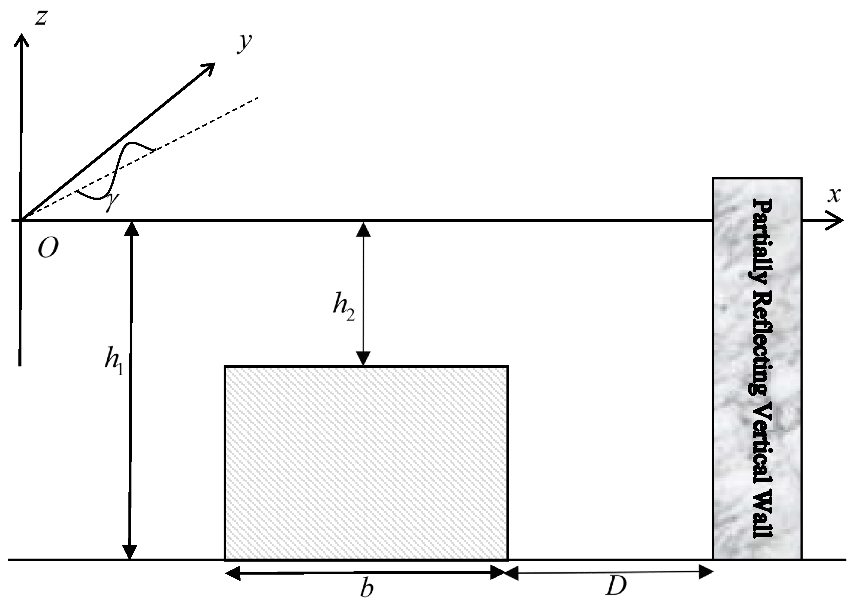
2.1. Problem Definition

The problem of wave scattering by breakwaters close to a partially reflecting vertical wall over an uneven bottom is examined in this subsection. A train of monochromatic waves with incidence angle γ , amplitude a ¯ , angular frequency σ , and wavelength λ , propagating from the left-hand side towards porous breakwaters and ending at a partially reflecting vertical wall over an uneven bottom is considered. Furthermore, the fluid is assumed to be irrotational and incompressible under the hypothesis of the small amplitude linear water wave theory [33] with continuous surface elevations. A schematic of this problem is shown in Figure 1. A Cartesian coordinate system is used, where the z -axis is considered vertically upwards and the x -axis denoting the horizontal plane. The wave motion is presumed to be time-harmonic by e i σ t , where t is the time, i is the unit of complex numbers, and σ is equal to 2 π / T with T being the wave period. The permeable breakwaters and uneven bottom are divided into M 1 shelves in the interval of x m 1 x x m for m = 1 , 2 , , M 1 in the step approximation. The shelves are separated by M 2 steps at x = x m for m = 1 , 2 , , M 2 . In addition, x 0 = is assumed and a partially reflecting vertical wall is located at x = x M 1 .
The velocity field ( x m 1 x x m ) on the m -th shelf for m = 1 , 2 , , M 1 is defined by
u m = ϕ m ,
where = ( / x , / y , / z ) and ϕ m are the velocity potential. The pressures in the water and porous layers are respectively defined as [34]:
P m = ρ i σ ϕ m + g z .
Sequentially, by applying the continuity condition to Equation (1), the Laplace equation results in:
2 ϕ m = 0 ,
Furthermore, the kinematic and dynamic boundary conditions are defined as follows:
i σ η m ϕ m z = 0
and
i σ ϕ m + g η m = 0   at   z = 0 ,
where η m represents the surface elevation. Combining Equations (4) and (5) yields
ϕ m z σ 2 g ϕ m = 0 ,
and the bottom boundary condition is
ϕ m z = 0   on   z = h m .
At the m -th step located at x = x m , the velocity potentials ϕ m and ϕ m + 1 require interface conditions
ϕ m x x = x m = ϕ m + 1 x x = x m
and
ϕ m x = x m = ϕ m + 1 x = x m ,   for min ( h m , h m + 1 ) z 0 ,
where
min ( h m , h m + 1 ) = h m   if   h m h m + 1 h m + 1   if   h m > h m + 1 .
In addition, the condition at the vertical wall reads as
ϕ x = 0   for max ( h m , h m + 1 ) z min ( h m , h m + 1 ) ,
where
max ( h m , h m + 1 ) = h m + 1   if   h m h m + 1 h m   if   h m > h m + 1
and ϕ refers to either ϕ m or ϕ m + 1 . Additionally, the partially reflecting condition of the vertical wall is expressed as:
ϕ M 1 x i k ^ M 1 , 0 1 K w 1 + K w ϕ M 1 x = x M 1 = 0 ,
where k ^ M 1 , 0 is the wavenumber defined in the next subsection and K w is a priori given as the partially reflecting factor of the vertical wall [2,33,35,36]. It needs to be mentioned that Equation (13) was originally developed without the effects of evanescent modes.
The far-field condition for the surface elevation of the incident wave is defined as:
η 1 = a ¯ e i k ^ 1 , 0 x + K R e i θ R e i k ^ 1 , 0 x e i k y y   as   x ,
where the reflection coefficient K R and phase angle θ R are real numbers, such that K R = K R e i θ R . In Equation (14), k y and k ^ 1 , 0 are positive real wavenumbers expressed as:
k ^ m , n = k m , n 2 k y 2
and
k y = k 1 , 0 sin γ ,
where k 1 , 0 = 2 π / λ > 0 and k M , 0 > 0 are the progressive wavenumbers satisfying the dispersion relation
σ 2 g = k m , 0 tanh k m , 0 h m .
In Equation (17), the indices vary as in m = 1 , 2 , , M 1 and n = 0 , 1 , . In addition, the evanescent wavenumbers k m , n in Equation (17) are defined as:
k m , n = i κ m , n ,
where the smallest positive root κ m , n satisfies the dispersion relation
σ 2 g = κ m , n tan κ m , n h m .

2.2. Eigenfunction Matching Method

In the eigenfunction expansion method, the velocity potential is defined as
ϕ m x , y , z = n = 0 N A m , n ξ m , n 1 x + B m , n ξ m , n 2 x ζ m , n z e i k y y
for m = 1 , 2 , 3 , , M 1 . In addition, A m , n and B m , n are unknowns. The eigenfunctions in Equation (20) can be defined as
ζ m , n z = cosh k m , n z + h m cosh k m , n h m ,
ξ m , n 1 x = e i k ^ m , n x x ¯ m 1 ,
and
ξ m , n 2 x = e i k ^ m , n x x ¯ m ,
where
x ¯ m = x m   for   m = 1 , 2 , , M 1 x ¯ 0 = 0 .
In Equation (20), k y denotes the incident wave transverse wavenumber, which is a constant according to Snell’s law [37] and the linear wave theory [33].
It can be noticed that the solutions defined by Equation (20) satisfy Equations (3), (6) and (7) analytically, and the unknowns A m , n and B m , n are determined by using Equations (8), (9), (11), (13) and (14).
The conversion of mass in Equations (8) and (11) can be formulated as
ϕ m x | ζ m , l larger = ϕ m + 1 x | ζ m , l larger   for   m = 1 , 2 , , M 2   and   l = 0 , 1 , , N ,
where the inner product of two vertical eigenfunctions is written as
G 1 | G 2 = h ˜ 0 G 1 z G 2 x d z
where G 1 and G 2 are the vertical eigenfunctions of ζ m , n with arbitrary m and n , and h ˜ denotes the water depth of the vertical eigenfunction G 1 . In Equation (25), the depth eigenfunction, ζ m , l larger , is defined as
ζ m , l larger = ζ m , l   for   h m > h m + 1 ζ m + 1 , l   for   h m + 1 > h m .
Furthermore, Equation (9) is represented as
ζ m , l smaller | ϕ m = ζ m , l smaller | ϕ m + 1   for   m = 1 , 2 , , M 2   and   l = 0 , 1 , , N ,
where
ζ m , l smaller = ζ m , l   for   h m < h m + 1 ζ m + 1 , l   for   h m + 1 < h m .
Furthermore, Equations (25) and (28) are valid for both h m > h m + 1 and h m + 1 > h m .
Then, based on Equations (5), (14), and (21), the far-field solution can be expressed as
ϕ 1 = i a ¯ g σ ζ 1 , 0 z e i k ^ 1 , 0 x + K R e i θ R e i k ^ 1 , 0 x e i k y y   as   x .
Substituting Equation (30) into Equation (20), yields
B 1 , 0 e i k ^ m , n x ¯ = i a ¯ K R e i θ R g σ ,
A 1 , 0 = i a ¯ g σ ,
and
A 1 , n = 0 ,  
where n = 1 , 2 , , N . In addition, combining the solution expression (20) and partially reflecting condition (13) yields
n = 0 N i k ^ M 1 , n A M 1 , n ξ M 1 , n 1 x M 1 i k ^ M 1 , n B M 1 , n ξ M 1 , n 2 x M 1 ζ M 1 , n ζ M 1 , l = i k ^ M 1 , 0 1 K w 1 + K w n = 0 N A M 1 , n ξ M 1 , n 1 x M 1 + B M 1 , n ξ M 1 , n 2 x M 1 ζ M 1 , l ζ M 1 , n
Finally, substituting the solution expression (20) into the conservation of mass (25) and momentum (28) results in
n = 0 N i k ^ m , n A m , n ξ m , n 1 x m i k ^ m , n B m , n ξ m , n 2 x m ζ m , n ζ m , l larger = n = 0 N i k ^ m + 1 , n A m + 1 , n ξ m + 1 , n 1 x m i k ^ m + 1 , n B m + 1 , n ξ m , n 2 x m ζ m + 1 , n ζ m , l larger
and
n = 0 N A m , n ξ m , n 1 x m + B m , n ξ m , n 2 x m ζ m , l smaller ζ m , n = n = 0 N A m + 1 , n ξ m , n 1 x m + B m + 1 , n ξ m , n 2 x m ζ m , l smaller ζ m + 1 , n ,
For m = 1 , 2 , , M 2 . Finally, the system of 2 M 1 ( N + 1 ) Equations (32)–(36) is solved to determine the unknowns A m , n and B m , n if the matrix system of the linear equations is nonsingular. Equation (31) is then used to evaluate the reflection coefficient K R . The SuperLU library is utilized in this study to evaluate the sparse matrix of the system of linear equations [38].

2.3. Wave Breaking and Dissipation

With the aid of the wave breaking and dissipation theory in MSE [27,28,30], the propagating wave number k ¯ m , 0 is described by the energy-dissipation factor f d as
k ¯ m , 0 2 = k ^ m , 0 2 1 + i f d .
Furthermore, Equations (22) and (23) are replaced by
ξ m , 0 1 x = e i k ¯ m , 0 x x ¯ m 1
and
ξ m , 0 2 x = e i k ¯ m , 0 x x ¯ m .
Based on the velocity potential (20), Equations (5) and (21), the surface elevation is expressed as
η m x , y = n = 0 N i σ A m , n g ξ m , n 1 x + i σ B m , n g ξ m , n 2 x e i k y y ,
where A m , n and B m , n are solved by Equations (32)–(36) by replacing Equations (22) and (23) and k ^ m , 0 by Equations (38) and (39) and k ¯ m , 0 , respectively.
The energy-dissipation factor f d is defined to complete the solution procedure. Therefore, empirical formulas are frequently used. In the literature [23,24], several wave-breaking indices have been presented. In the present study, the Goda [20] wave-breaking index is used as
γ b = 0.17 1 exp 1.5 π h m λ 1 + 15 β 4 3 ,
where β is the bottom slope. Therefore, wave breaking occurs when
2 η m h m > γ b ,
where η m is calculated by Equation (40). When the condition (42) is satisfied in the breaking zone, the energy dissipation factor f d is assessed by
f d = 0.15 k m , 0 h m 1 0.2 h m η m 2
or
f d = 2.5 β 1 k 1 , 0 h m η m / h m 0.135 0.4 0.57 + 5.3 β 0.135 ,
as defined by Dally et al. [25] and Isobe [27], respectively. Wave breaking occurs only when the slope is not negative since the wave comes from the left-hand side. In Equation (41), only slopes that are non-negative are taken into account.
Iterations are required in the solution process because the surface elevation η m and the energy-dissipation factor f d are interdependent. More precisely, the wave-breaking condition (42) was employed from the surface elevation η m determined by f d = 0 . The energy-dissipation factor and surface elevation are iteratively updated until the maximum norm between two consecutive surface elevations is less than 10 5 m . This leads to a surface elevation as a result of transformation of waves owing to the breaking, dissipating, and variable bottoms.

2.4. Wave Force

The dynamic pressure on the wall can be evaluated using Equation (2) as
p M 1 x = x M 1 = i ρ σ ϕ M 1 x = x M 1 .
By integrating the dynamic pressure along the vertical wall, the dimensionless horizontal wave force is obtained by the normalization factor 2 a ¯ ρ g h M 1 as
K F = i σ h M 1 0 ϕ M 1 d z x = x M 1 2 a ¯ g h M 1 .
Sequentially, substituting the solution expression Equation (20) into the above equation gives the required formula for the non-dimensional wave force on the wall as
K F = i σ n = 0 N A M 1 , n ξ M 1 , n 1 x M 1 + B M 1 , n ξ M 1 , n 2 x M 1 h M 1 0 ζ M 1 , n z d z 2 a ¯ g h M 1 .
In deriving Equation (40), the transverse wave function e i k y y is neglected as the equation is normalized by considering its maximum value in the transverse direction.

3. Results

In this section, the EMM model is validated by comparing its results with those found in the literature. Several cases of wave scattering, breaking, and dissipation by breakwaters or variable bottoms in front of a partially reflecting wall are considered. The convergence is assessed by examining the test cases.

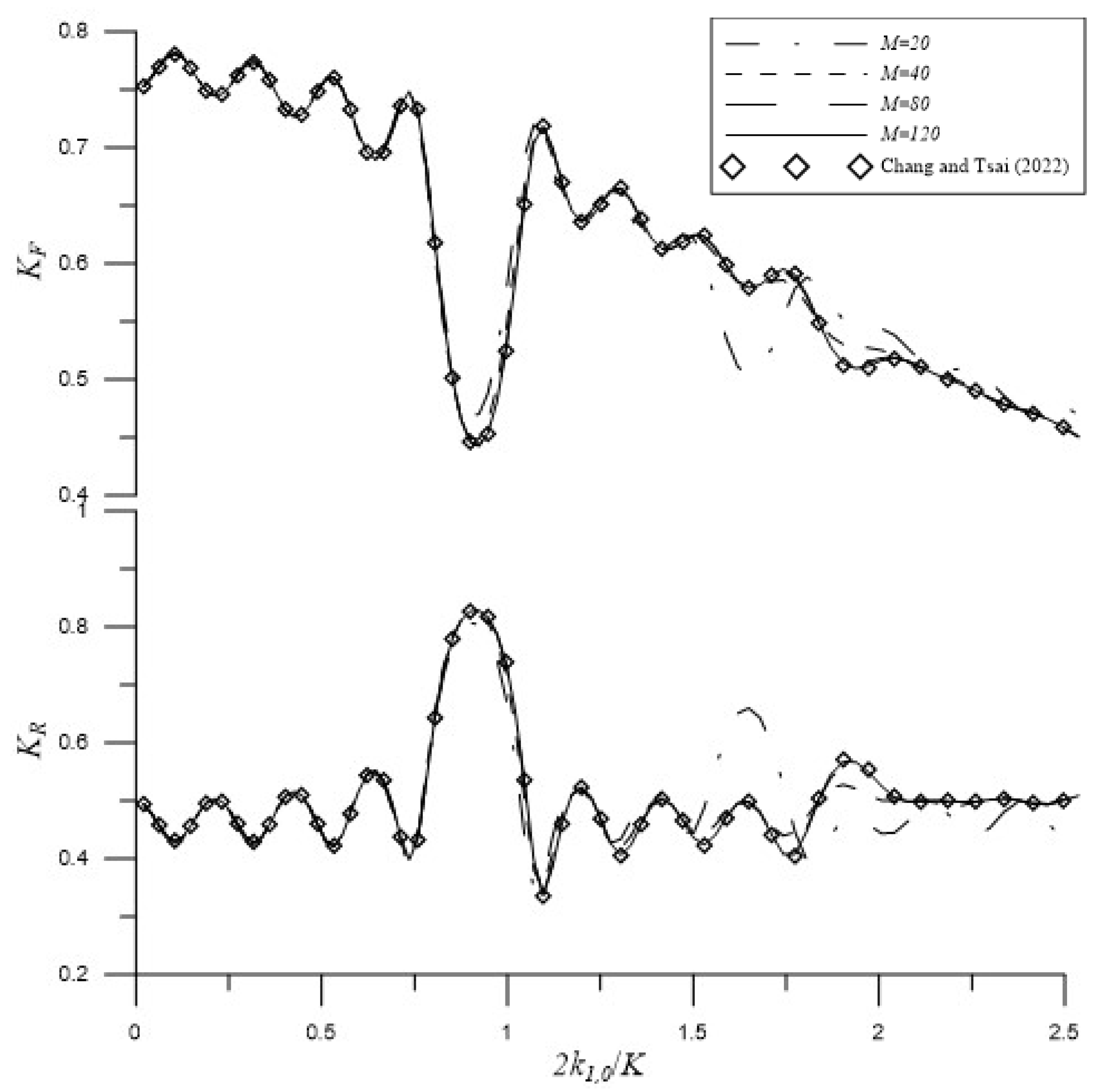
3.1. Rectangular Breakwater Close to a Partially Reflecting Vertical Wall

Following Zhao et al. [35], we consider the problem of water wave scattering by a rectangular breakwater near a partially reflecting vertical wall over a uniform bottom with k 1 , 0 h 1 = 1.2 , γ = 0 , K w = 0.8 , D / h 1 = 3 , and h 2 / h 1 = 0.5 as depicted in Figure 2. To study the convergence of the solution, the dimensionless wave force K F is plotted against the dimensionless breakwater width b / λ as depicted in Figure 3. Here, Equation (47) is used for evaluating the dimensionless wave force. From the figures, it can be seen that the convergence is obtained for N = 4 . Furthermore, the computational results based on the present theory coincide with those of Zhao et al. [35].
Overall, this numerical example illustrates that the eigenfunction matching method can be utilized to solve the normal scattering of water waves by a rectangular permeable breakwater near a partially reflecting vertical wall.

3.2. Constructive and Destructive Bragg Scattering by Periodic Half-Cosine Shaped Breakwaters

Subsequently, the proposed EMM is validated for solving problems with variable bottoms. Following Chang and Tsai [39], we consider the constructive and destructive Bragg scattering by four periodic half-cosine-shaped breakwaters placed near a partially reflecting wall as depicted in Figure 4. Following Kirby and Anton [40] and Tsai et al. [41], the water depth and amplitude of the half-cosine-shaped breakwaters are set as h 1 = 0.15 m and a = 0.05 m , respectively. Additionally, the wavelength of the periodic bottom and the separation distance between the half-cosine-shaped breakwaters are defined by 2 π / K = 0.8 m and d = 0.5 m , respectively. The vertical wall is separated from the toe of the last breakwater by D .
Chang and Tsai [39] initially investigated the constructive Bragg scattering, in which multiple breakwaters should be periodically located with the wavelength equal to half of the significant wavelength of the coastal wave environment, and the partially vertical wall should be located by a quarter of the significant wavelength away from the last breakwater. In this situation, the wave forces on the wall can be significantly reduced. Figure 5. describes the reflection coefficient and dimensionless wave force obtained using the proposed EMM model with D = 0.4 m and K w = 0.5 . Similar to the previous example, N = 4 is adopted in this subsection. In the figure, it can be observed that the convergence is obtained for shelf numbers up to M = 120 , and the results agree with those in the literature. In addition, the primary Bragg resonances can be observed to be constructive as the wave forces migrate significantly, especially when 2 k 1 , 0 / K .
Similarly, the destructive Bragg scattering is configured by D = 0.8 m and K w = 0.5 . Figure 6 depicts the reflection coefficient and dimensionless wave force obtained using the proposed model. In the figure, convergent results can be found with M = 120 and the results agree well with those in Chang and Tsai [39]. In addition, the Bragg resonances can be observed to be destructive. These results suggest that the separation distance should not be close to the wavelength of the periodic bottom so that extreme wave forces on the vertical wall can be avoided.
In summary, this numerical example demonstrates that the EMM can be used to solve the problem of the typical scattering of waves by variable breakwaters placed near a partially reflecting vertical wall.

3.3. Oblique Incidence

Then, the proposed EMM is also validated for its capacity to solve problems of oblique Bragg scattering as the significant wave angle, γ , is sometimes not parallel to the normal direction of the shoreline in real coastal environments.
In this subsection, the constructive Bragg scattering in Figure 5 is extended by considering γ = 30 ° and K w = 0.2 with the separation distance maintained as D = 0.4 m . Figure 7 gives the convergence results of the reflection coefficient and dimensionless wave force with respect to the shelf numbers. In the figure, it is significant to observe that the Bragg resonances are constructive, particularly at 2 k 1 , 0 cos γ / K ~ 1 . This confirms Bragg’s theory for oblique waves [42,43].

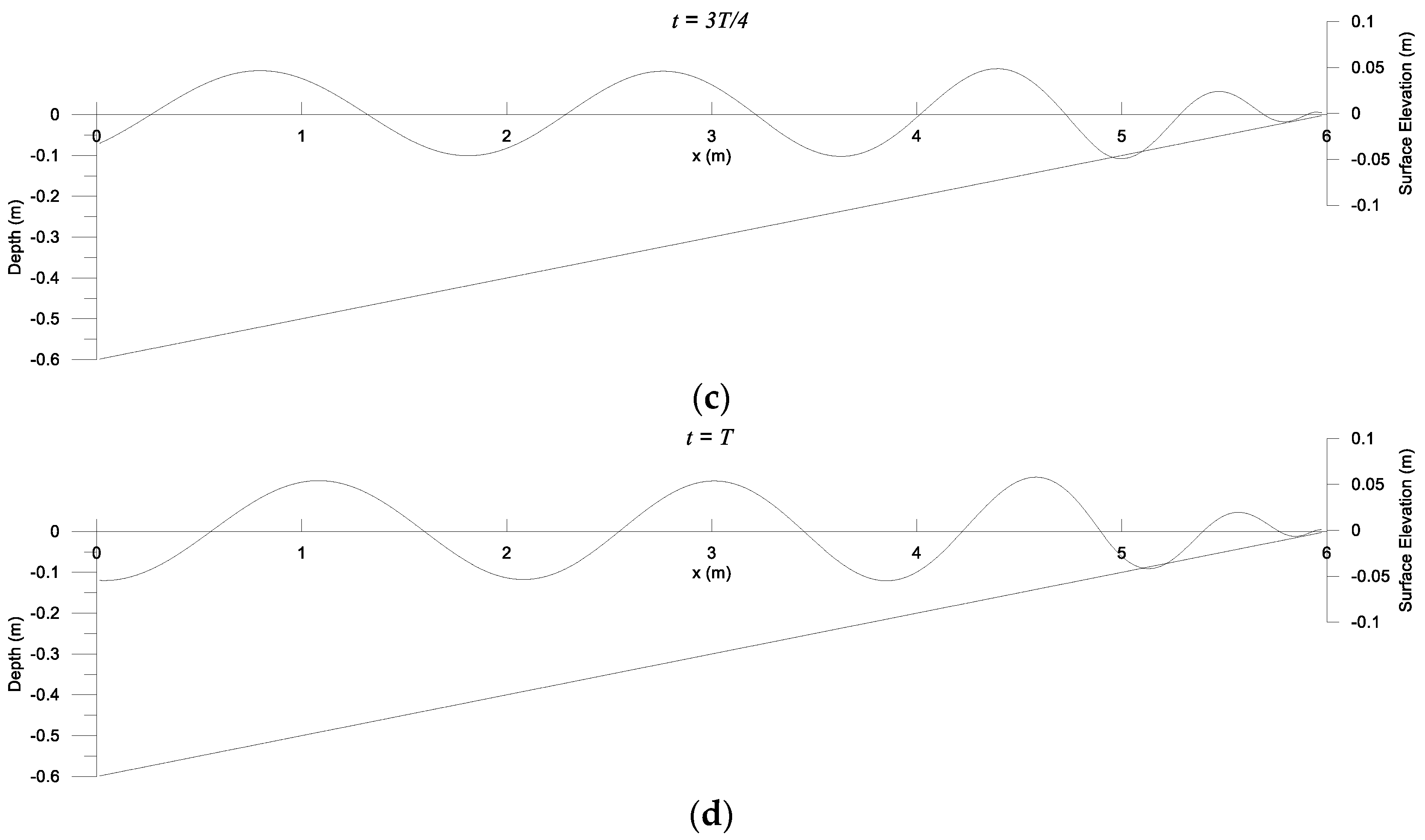
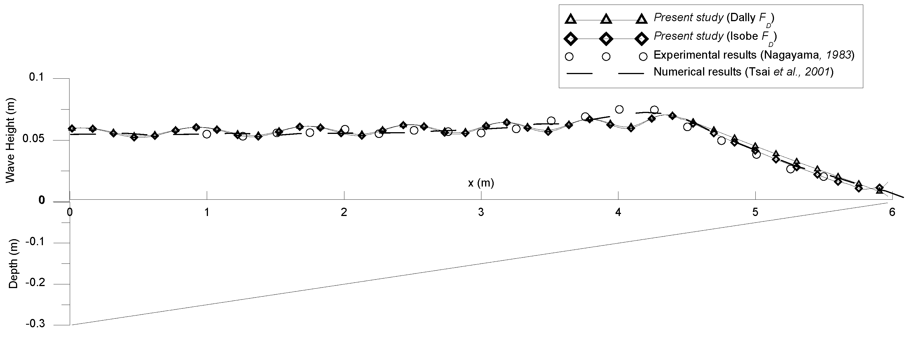
3.4. Water Wave Breaking and Dissipation by Mild Slopes

In this subsection, the eigenfunction matching method is validated for its capacity to analyze water-wave breaking and dissipation by mild slopes.
Following Tsai et al. [28], we consider water-wave breaking and dissipation by a slope of 1 / 10 with the normally incident wave of period T = 1.205 s and wave height 2 a ¯ = 0.1104 m from the far field with a water depth of h 1 = 0.6 m . Figure 8 demonstrates the numerical wave heights attained by the EMM with various numbers of evanescent modes N and shelves M . Here, K w = 0 is adopted to approximate the shoreline. From the figures, it is noticeable that the convergence is attained for M = 200 and N = 2 , which are then adopted in this subsection. The EMM solutions are subsequently validated as they agree well with the experimental data [44] and the MSE numerical results [28], as shown in Figure 9. In the figures, the energy-dissipation factors are evaluated by the empirical Formulas (43) and (44) of Dally et al. [25] and Isobe [27], respectively.
Figure 10 depicts the surface elevations at various wave phases, with the energy-dissipation factor calculated using Isobe’s formula [27]. It is also noticeable that the wave shoaling and energy dissipation are due to the slope.
Subsequently, a second example is considered for the water-wave breaking and dissipation by a slope of 1 / 20 with the wave of period T = 1.19 s and height 2 a ¯ = 0.06 m from the far field with a water depth of h 1 = 0.6 m . Figure 11 depicts the comparison between the numerical wave heights attained using the EMM, experimental data obtained by Nagayama [45], and the MSE numerical results [28]. A good agreement can also be observed from the figure.
Overall, the numerical solutions given in this subsection validate the applications of the proposed EMM for solving water-wave breaking and dissipation by mild slopes.

4. Discussion

In this section, a parametric analysis will be performed for the problem considered in Section 3.1. Subsequently, the EMM will be further applied to problems of wave breaking and dissipation by steep slopes, composite slopes, and a barred beach. Some discussions will be provided.

4.1. Parametric Analysis on Wave Scattring by Rectangular Breakwater in Front of Partially Reflecting Vertical Wall

As analytical solutions for scattering of waves by breakwaters placed near a partially reflecting vertical wall have rarely been reported in the literature. Parametric analysis will be performed for the problem considered in Section 3.1 as described in Figure 2. These results provide benchmark data for future studies on similar problems. Following the studies presented in Section 3.1, N = 4 is considered in this subsection.
To study the effects of the wall partially reflecting factors K w on the hydrodynamic quantities, the other parameters are fixed as those in Section 3.1. Figure 12 depicts the dimensionless wave force K F and reflection coefficient K R as functions of the dimensionless breakwater width b / λ with normal incidence. As shown in the figure, the values of the reflection coefficient K R are basically proportional to the partially reflecting factors K w . In addition, the cases with larger partially reflecting factors yield larger wave forces on the vertical walls. Similar results can also been found in Figure 13 but with an oblique incidence of γ = 30 ° .
.
Subsequently, the effects of the breakwater heights were studied with the other parameters fixed as those in Section 3.1. Figure 14 describes the dimensionless wave force K F and reflection coefficient K R as functions of the dimensionless breakwater width b / λ with different values of h 2 / h 1 . As shown in the figure, the cases with larger breakwater heights, smaller values of h 2 / h 1 , have the larger wave forces and smaller reflection coefficients, as expected.

4.2. Wave Breaking and Dissipation by Steep Slopes

Section 3.4 is extended by considering steep slopes of 1 / 5 and 1 / 3 , and the numerical results will be compared with the experimental data of Tsai et al. [29]. Following the numerical studies presented in Section 3.4, M = 200 and N = 2 are adopted in this subsection.
First, we consider the problem of a slope of 1 / 5 with a wave period of T = 2.6 s and a wave height of 2 a ¯ = 0.106 m from the far field with a water depth of h 1 = 0.885 m . The EMM solutions shown in Figure 15. indicate that the numerical wave height obtained using the EMM based on the energy-dissipation factor of Dally et al. [25] agree well with the experimental data of Tsai et al. [29]. However, the numerical wave heights based on Isobe’s [27] energy-dissipation factor cease to dissipate on the downstream flat bottom as f d = 0 if β = 0 in Equation (44).
Second, we consider an example that has a slope of 1 / 3 , a wave period of T = 1.8 s , and a wave height of 2 a ¯ = 0.202 m from the far field with a water depth of h 1 = 0.970 m . Figure 16 depicts a comparison between numerical wave heights obtained by the EMM and the experimental data obtained by Tsai et al. [29]. A good agreement is also observed for the numerical wave height obtained by the EMM based on the energy-dissipation factor formulated by Dally et al. [25], as shown in the figure.
Overall, the numerical solutions given in this subsection validate the applications of the proposed EMM for solving water-wave breaking and dissipation by steep slopes. In addition, the energy-dissipation factor formulated by Dally et al. [25] is preferred if wave dissipation occurs on a flat bottom.

4.3. Wave Breaking and Dissipation by Composite Slopes

Next, we consider the breaking and dissipation of waves by composite slopes of 1 / 20 separated by a flat region of length 2 m . The normal incident wave has a period of T = 1.18 s and a wave height of 2 a ¯ = 0.07 m and is from the far field with a water depth of h 1 = 0.25 m . In this subsection, M = 200 and N = 2 are also adopted. In addition, K w = 0 is adopted to approximate the shoreline. Figure 17 shows a comparison between the numerical wave heights obtained by the EMM, the experimental data of Nagayama [45], and the MSE numerical results of Lan et al. [30]. Good agreements can also be observed from the figure for the numerical wave heights attained by the EMM based on the energy-dissipation factor formulated by Dally et al. [25] as the wave dissipation occurs on the flat separation.

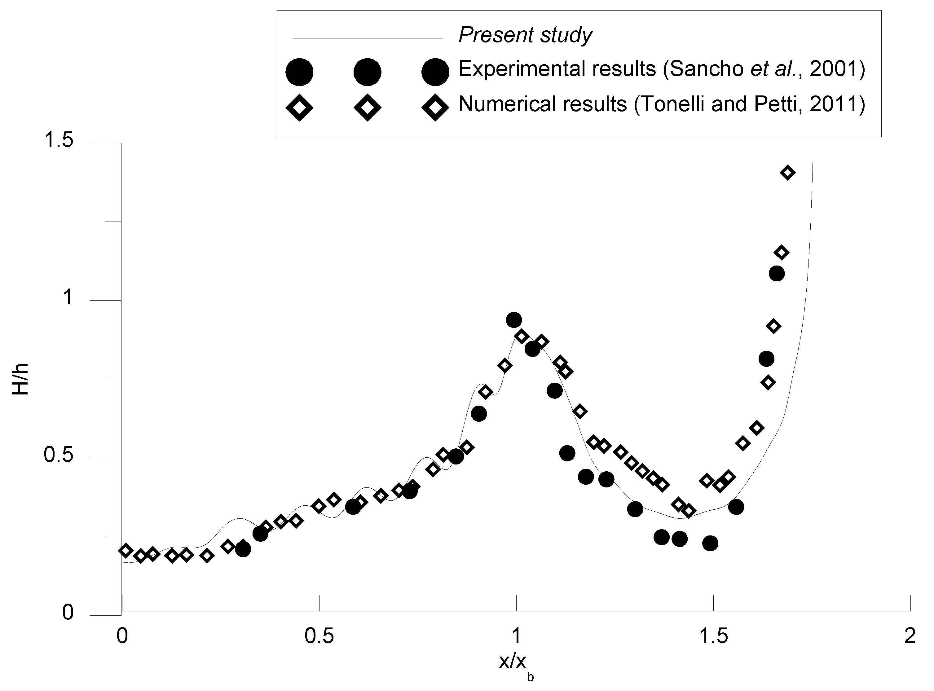
4.4. Wave Breaking and Dissipation by a Barred Beach

Sancho et al. [46] conducted experiments on the wave breaking and dissipation of water waves by a barred beach. The barred beach has a variable bottom profile as depicted in Figure 18. Two cases of spilling and plunging breakings are considered by the incident waves of T = 2.5 s & 2 a ¯ = 0.21 m and T = 3.5 s & 2 a ¯ = 0.38 m , respectively. Figure 18. demonstrates the numerical wave heights obtained by the EMM with different numbers of evanescent shelves M and N = 2 . Here, K w = 0 is adopted to approximate the shoreline. The figures show that the convergence is obtained for M = 1000 and N = 2 , which are then adopted in this subsection. Based on the previous discussions, the energy-dissipation factor was modeled by the empirical formula developed by Dally et al. [25] in this subsection.
For the spilling breaking case, the EMM solutions are compared with the experimental data [46] and numerical results obtained using the Boussinesq equations of Tonelli and Petti [47] and D’Alessandro and Tomasicchio [48], as shown in Figure 19. In the figure, good agreements can be observed. For the plunging case, the EMM solutions are compared with the experimental data of Sancho et al. [46] and the Boussinesq numerical results obtained by Tonelli and Petti [47], as depicted in Figure 20.
Overall, the numerical results presented in this subsection indicate that the proposed model can be implemented to solve problems of wave dissipation with variable bottoms after both spilling and plunging breakings.

5. Conclusions

In this study, the scattering, breaking, and dissipation of water waves by variable bottoms across the surf zone were investigated. In the solution procedure, shelves among steps are employed to approximate the geometric profiles of the varied bottom across the surf zone, and the coastline is set up as a partially reflective vertical wall. By employing the conservations of mass and momentum on the steps, the eigenfunctions over the shelves are matched. The impacts of breaking and energy dissipation are implemented in the proposed eigenfunction matching method using the energy-dissipation factors, which are modeled using empirical formulae. The results of the proposed model agree well with experimental data available in the literature. Some benchmark results for oblique wave scattering by a rectangular breakwater placed near a partially reflecting vertical wall were provided and discussed. In addition, the proposed model with different empirical formulae was discussed and applied to solve the breaking and dissipation of water waves by different variable bottoms. The numerical results indicate that the proposed method with the energy-dissipation factor modelled by the empirical formula developed by Dally et al. [25] is more suitable, especially when wave dissipations occur on a flat region of the bottom.
The proposed EMM is a depth-integrated model that assumes irrational, harmonic, and linear waves. The impacts of the breaking and dissipation of waves can be affected by the energy-dissipation factor in the EMM formulation. In addition, the current model is computationally efficient and can be used as preliminary calculations, followed by modern three-dimensional numerical models. These are currently under investigation.

Author Contributions

Conceptualization, C.-C.T.; methodology, J.-Y.C. and C.-C.T.; software, C.-C.T.; writing-original draft, J.-Y.C.; visualization, J.-Y.C. All authors have read and agreed to the published version of the manuscript.

Funding

This research was funded by the Ministry of Science and Technology of Taiwan under the Grant No. MOST 109-2221-E-992-046-MY3.

Institutional Review Board Statement

Not applicable.

Informed Consent Statement

Not applicable.

Data Availability Statement

Not applicable.

Acknowledgments

The Ministry of Science and Technology of Taiwan is gratefully acknowledged for providing financial support.

Conflicts of Interest

The authors declare no conflict of interest exist.

References

  1. Goda, Y. Random Seas and Design of Maritime Structures; World Scientific Publishing: Singapore, 2010. [Google Scholar]
  2. Isaacson, M.; Qu, S. Waves in a harbour with partially reflecting boundaries. Coast. Eng. 1990, 14, 193–214. [Google Scholar] [CrossRef]
  3. Elchahal, G.; Younes, R.; Lafon, P. The effects of reflection coefficient of the harbour sidewall on the performance of floating breakwaters. Ocean Eng. 2008, 35, 1102–1112. [Google Scholar] [CrossRef]
  4. Behera, H.; Khan, M.B. Numerical modeling for wave attenuation in double trapezoidal porous structures. Ocean Eng. 2019, 184, 91–106. [Google Scholar] [CrossRef]
  5. Pakozdi, C.; Kendon, T.E.; Stansberg, C.-T. Breaking Wave Impact on a Platform Column: An Introductory CFD Study. In Proceedings of the ASME 2011 30th International Conference on Ocean, Offshore and Arctic Engineering, Rotterdam, The Netherlands, 19–24 June 2011; pp. 645–654. [Google Scholar]
  6. Xiang, T.; Istrati, D.; Yim, S.C.; Buckle, I.G.; Lomonaco, P. Tsunami loads on a representative coastal bridge deck: Experimental study and validation of design equations. J. Waterw. Port Coast. Ocean. Eng. 2020, 146, 04020022. [Google Scholar] [CrossRef]
  7. Berkhoff, J.C.W. Computation of combined refraction-diffraction. In Proceedings of the 13th International Conference on Coastal Engineering, Vancouver, BC, Canada, 10–14 July 1972; pp. 471–490. [Google Scholar]
  8. Takano, K. Effets d’un obstacle parallelepipedique sur la propagation de la houle. La Houille Blanche 1960, 15, 247–267. [Google Scholar] [CrossRef] [Green Version]
  9. Massel, S.R. Extended refraction-diffraction equation for surface waves. Coast Eng. 1993, 19, 97–126. [Google Scholar] [CrossRef]
  10. Belibassakis, K.; Touboul, J.; Laffitte, E.; Rey, V. A mild-slope system for bragg scattering of water waves by sinusoidal bathymetry in the presence of vertically sheared currents. J. Mar. Sci. Eng. 2019, 7, 9. [Google Scholar] [CrossRef] [Green Version]
  11. Belibassakis, K.; Touboul, J. A nonlinear coupled-mode model for waves propagating in vertically sheared currents in variable bathymetry—Collinear waves and currents. Fluids 2019, 4, 61. [Google Scholar] [CrossRef] [Green Version]
  12. O’Hare, T.J.; Davies, A.G. A comparison of two models for surface-wave propagation over rapidly varying topography. Appl. Ocean Res. 1993, 15, 1–11. [Google Scholar] [CrossRef]
  13. Devillard, P.; Dunlop, F.; Souillard, B. Localization of gravity waves on a channel with a random bottom. J. Fluid Mech. 1988, 186, 521–538. [Google Scholar] [CrossRef]
  14. Tsai, C.C.; Lin, Y.-T.; Hsu, T.-W. On the weak viscous effect of the reflection and transmission over an arbitrary topography. Phys. Fluids 2013, 25, 043103–043121. [Google Scholar] [CrossRef]
  15. Tsai, C.-C.; Tai, W.; Hsu, T.-W.; Hsiao, S.-C. Step approximation of water wave scattering caused by tension-leg structures over uneven bottoms. Ocean Eng. 2018, 166, 208–225. [Google Scholar] [CrossRef]
  16. Tseng, I.-F.; You, C.-S.; Tsai, C.-C. Bragg reflections of oblique water waves by periodic surface-piercing and submerged breakwaters. J. Mar. Sci. Eng. 2020, 8, 522. [Google Scholar] [CrossRef]
  17. Tran, C.-T.; Chang, J.-Y.; Tsai, C.-C. Step approximation for water wave scattering by multiple thin barriers over undulated bottoms. J. Mar. Sci. Eng. 2021, 9, 629. [Google Scholar] [CrossRef]
  18. Tsai, C.-C.; Chou, W.-R. Comparison between consistent coupled-mode system and eigenfunction matching method for solving water wave scattering. J. Mar. Sci. Technol.-Taiw. 2015, 23, 870–881. [Google Scholar] [CrossRef]
  19. McCowan, J. XXXIX. On the highest wave of permanent type. Lond. Edinb. Dublin Philos. Mag. J. Sci. 1894, 38, 351–358. [Google Scholar] [CrossRef] [Green Version]
  20. Goda, Y. A Synthesis of Breaker Indices. Proc. Jpn. Soc. Civ. Eng. 1970, 1970, 39–49. [Google Scholar] [CrossRef] [PubMed]
  21. Weggel, R.J. Maximum Breaker Height. J. Waterw. Harb. Coast. Eng. Div. 1972, 98, 529–548. [Google Scholar] [CrossRef]
  22. Svendsen, I. Analysis of surf zone turbulence. J. Geophys. Res. 1987, 92, 5115–5124. [Google Scholar] [CrossRef]
  23. Goda, Y. Reanalysis of Regular and random breaking wave statistics. Coast. Eng. J. 2010, 52, 71–106. [Google Scholar] [CrossRef]
  24. Robertson, B.; Hall, K.; Zytner, R.; Nistor, I. Breaking Waves: Review of Characteristic Relationships. Coast. Eng. J. 2013, 55, 1350002. [Google Scholar] [CrossRef]
  25. Dally, W.R.; Dean, R.G.; Dalrymple, R.A. Wave height variation across beaches of arbitrary profile. J. Geophys. Res. 1985, 90, 11917–11927. [Google Scholar] [CrossRef]
  26. Battjes, J.A.; Janssen, J.P.F.M. Energy loss and set-up due to breaking of random waves. Coast. Eng. Proc. 1978, 1, 32. [Google Scholar] [CrossRef] [Green Version]
  27. Isobe, M. A parabolic equation model for transformation of irregular waves due to refraction, diffraction and breaking. Coast. Eng. Jpn. 1987, 30, 33–47. [Google Scholar] [CrossRef]
  28. Tsai, C.-P.; Chen, H.-B.; Hsu, J.R.C. Calculations of wave transformation across the surf zone. Ocean Eng. 2001, 28, 941–955. [Google Scholar] [CrossRef]
  29. Tsai, C.-P.; Chen, H.-B.; Hwung, H.-H.; Huang, M.-J. Examination of empirical formulas for wave shoaling and breaking on steep slopes. Ocean Eng. 2005, 32, 469–483. [Google Scholar] [CrossRef]
  30. Lan, Y.-J.; Kuo, Y.-S.; Hsu, T.-W.; Lin, T.-Y. Numerical simulation of wave transformation across the surf zone over a steep bottom. Ocean Eng. 2012, 41, 33–38. [Google Scholar] [CrossRef]
  31. Hsu, T.-W.; Chang, J.-Y.; Lan, Y.-J.; Lai, J.-W.; Ou, S.-H. A parabolic equation for wave propagation over porous structures. Coast Eng. 2008, 55, 1148–1158. [Google Scholar] [CrossRef] [Green Version]
  32. Tsai, C.-C.; Chang, Y.-H.; Hsu, T.-W. Step approximation on oblique water wave scattering and breaking by variable porous breakwaters over uneven bottoms. Ocean Eng. 2022, 253, 111325. [Google Scholar] [CrossRef]
  33. Mei, C.C.; Stiassnie, M.A.; Yue, D.K.-P. Theory and Applications of Ocean Surface Waves: Part 1: Linear Aspects; World Scientific: Singapore, 2005. [Google Scholar]
  34. Silva, R.; Salles, P.; Palacio, A. Linear waves propagating over a rapidly varying finite porous bed. Coast Eng. 2002, 44, 239–260. [Google Scholar] [CrossRef]
  35. Zhao, Y.; Liu, Y.; Li, H. Wave interaction with a partially reflecting vertical wall protected by a submerged porous bar. J. Ocean. Univ. China 2016, 15, 619–626. [Google Scholar] [CrossRef]
  36. Zhao, Y.; Li, H.-j.; Liu, Y. Oblique wave scattering by a submerged porous breakwater with a partially reflecting sidewall. J. Mar. Sci. Technol. 2017, 25, 3. [Google Scholar]
  37. Meade, R.; Winn, J.N.; Joannopoulos, J. Photonic Crystals: Molding the Flow of Light; Pinceton Univiversity Press: Princeton, NJ, USA, 2008; p. 305. [Google Scholar]
  38. Li, X.S. An overview of SuperLU: Algorithms, implementation, and user interface. ACM Trans. Math. Softw. 2005, 31, 302–325. [Google Scholar] [CrossRef]
  39. Chang, J.-Y.; Tsai, C.-C. Wave forces on a partially reflecting wall by oblique Bragg scattering with porous breakwaters over uneven bottoms. J. Mar. Sci. Eng. 2022, 10, 409. [Google Scholar] [CrossRef]
  40. Kirby, J.T.; Anton, J.P. Bragg Reflection of Waves by Artificial Bars. In Coastal Engineering 1990; ASCE: Reston, VA, USA, 1991; pp. 757–768. [Google Scholar]
  41. Tsai, C.-C.; Lin, Y.-T.; Chang, J.-Y.; Hsu, T.-W. A coupled-mode study on weakly viscous Bragg scattering of surface gravity waves. Ocean Eng. 2016, 122, 136–144. [Google Scholar] [CrossRef]
  42. Mei, C.C. Resonant reflection of surface water waves by periodic sandbars. J. Fluid Mech. 1985, 152, 315–335. [Google Scholar] [CrossRef]
  43. Dalrymple, R.A.; Kirby, J.T. Water waves over ripples. J. Waterw. Port Coast. Ocean. Eng. 1986, 112, 309–319. [Google Scholar] [CrossRef] [Green Version]
  44. Tsai, C.-P.; Chen, H.-B.; Hsu, H.T. Estimation of wave height deformation in surf zone. J. Harb. Technol. 1995, 10, 93–111. [Google Scholar]
  45. Nagayama, S. Study on the Change of Wave Height and Energy in the Surf Zone. Bachelor’s Thesis, Yokohama National University, Yokohama, Japan, 1983. [Google Scholar]
  46. Sancho, F.; Mendes, P.; Carmo, J.; Neves, M.; Tomasicchio, G.; Archetti, R.; Damiani, L.; Mossa, M.; Rinaldi, A.; Gironella, X. Wave Hydrodynamics over a Barred Beach. In Ocean Wave Measurement and Analysis 2001; ASCE: Reston, VA, USA, 2002; pp. 1170–1179. [Google Scholar]
  47. Tonelli, M.; Petti, M. Simulation of wave breaking over complex bathymetries by a Boussinesq model. J. Hydraul. Res. 2011, 49, 473–486. [Google Scholar] [CrossRef]
  48. D’Alessandro, F.; Tomasicchio, G.R. The BCI criterion for the initiation of breaking process in Boussinesq-type equations wave models. Coast Eng. 2008, 55, 1174–1184. [Google Scholar] [CrossRef]
Figure 1. Wave scattering by variable bottoms near a partially reflecting vertical wall.
Jmse 11 00062 g001
Figure 2. Problem definition of wave scattering by a rectangular breakwater near a partially reflecting wall.
Jmse 11 00062 g002
Figure 3. Dimensionless wave force varying against dimensionless breakwater width for scattering of incident waves by a rectangular structure placed near a partially reflecting vertical wall [35].
Jmse 11 00062 g003
Figure 4. Problem definition of the oblique constructive and destructive Bragg scattering by four periodic half-cosine-shaped breakwaters placed near a partially reflecting wall.
Jmse 11 00062 g004
Figure 5. Variation of wave reflection and dimensionless wave force varying against 2 k 1 , 0 / K for the constructive Bragg scattering by four periodic half-cosine-shaped breakwaters placed near a partially reflecting wall [39].
Jmse 11 00062 g005
Figure 6. Variation of wave reflection and dimensionless wave force varying against 2 k 1 , 0 / K for the destructive Bragg scattering by four periodic half-cosine-shaped breakwaters placed close to a partially reflecting vertical wall [39].
Jmse 11 00062 g006
Figure 7. Reflection coefficient and dimensionless wave force varying against 2 k 1 , 0 cos γ / K for the oblique constructive Bragg scattering by four periodic half-cosine shaped breakwaters placed near a partially reflecting vertical wall [39].
Jmse 11 00062 g007
Figure 8. Wave heights for breaking and dissipation of waves by a slope of 1 / 10 for various numbers of (a) evanescent modes and (b) shelves.
Jmse 11 00062 g008
Figure 9. Wave heights for breaking and dissipation of waves by a slope of 1 / 10 with various formulas of energy dissipation factors [25,27,28,44].
Jmse 11 00062 g009
Figure 10. The change in surface elevations at various wave phases for scattering of waves (a) t = T/4 (b) t = T/2 (c) t = T3/4 (d) t = T by a slope of 1 / 10 .
Jmse 11 00062 g010aJmse 11 00062 g010b
Figure 11. Wave heights for breaking and dissipation of waves by a slope of 1 / 20 for varying formulas of energy dissipation factors [25,27,28,45].
Jmse 11 00062 g011
Figure 12. Effects of the wall partially reflecting factors Kw on the dimensionless wave force and reflection coefficient with normal incidence.
Jmse 11 00062 g012
Figure 13. Effects of the wall partially reflecting factors Kw on the dimensionless wave force and reflection coefficient with oblique incidence of γ = 30 ° .
Jmse 11 00062 g013
Figure 14. Effects of the breakwater heights on the dimensionless wave force and reflection coefficient.
Jmse 11 00062 g014
Figure 15. Wave heights for breaking and dissipation of wave by a slope of 1 / 5 with varying formulas of energy dissipation factors [25,27,29].
Jmse 11 00062 g015
Figure 16. Wave heights for breaking and dissipation of wave by a slope of 1 / 3 with varying formulas of energy dissipation factors [25,27,29].
Jmse 11 00062 g016
Figure 17. Wave heights for breaking and dissipation of waves by composite slopes of 1 / 20 with varying formulas of energy dissipation factors [25,27,30,45].
Jmse 11 00062 g017
Figure 18. Wave heights for wave breaking and dissipation by a barred beach with various numbers of shelves for the (up) spilling and (down) plunging breaking cases.
Jmse 11 00062 g018aJmse 11 00062 g018b
Figure 19. Comparisons of wave heights for breaking and dissipation of waves by a barred beach for the spilling breaking case [46,47,48].
Jmse 11 00062 g019
Figure 20. Comparisons of wave heights for breaking and dissipation of waves by a barred beach for the plunging breaking case [46,47].
Jmse 11 00062 g020
Disclaimer/Publisher’s Note: The statements, opinions and data contained in all publications are solely those of the individual author(s) and contributor(s) and not of MDPI and/or the editor(s). MDPI and/or the editor(s) disclaim responsibility for any injury to people or property resulting from any ideas, methods, instructions or products referred to in the content.

