Article

Optimization Design of Pressure Hull for Long-Range Underwater Glider Based on Energy Consumption Constraints

Institute of Marine Mechatronics Equipment, School of Mechanical Science and Engineering, Huazhong University of Science and Technology, Wuhan 430074, China
*
Author to whom correspondence should be addressed.
J. Mar. Sci. Eng. 2023, 11(1), 202; https://doi.org/10.3390/jmse11010202
Submission received: 21 November 2022 / Revised: 28 December 2022 / Accepted: 3 January 2023 / Published: 12 January 2023
(This article belongs to the Section Ocean Engineering)

Abstract

:
Underwater gliders are a class of ocean observation equipment driven by buoyancy, and their energy consumption source is mainly generated by the active regulation of buoyancy. The periodic elastic deformation of the pressure hull during the upward and downward movement of the underwater glider can have a large impact on its driving buoyancy. This paper relates the optimization problem of the pressure hull with the energy consumption of underwater glider, and the energy improvement factor is taken as the optimization objective. Based on the mechanical theory, the theoretical optimization model and constraint model are derived. A hybrid genetic simulated annealing algorithm (HGSAA) is adopted to optimize the pressure hull of the underwater glider developed by Huazhong University of Science and Technology (HUST). Additionally, the effectiveness of the optimized mathematical model and optimization results were verified by the tests. The sea trial results show that after the pressure hull optimization, the energy consumption of the buoyancy regulation unit decreased by 21.9%, and the total energy carried increased by 12.4%.

1. Introduction

Underwater gliders are a class of ocean observation platforms that originated from drifting buoys. The gliders achieve a zigzag profile gliding by changing their net buoyancy periodically and using lift forces generated by the fixed wings to convert this vertical motion into forwarding velocity [1]. It is a typical weakly controllable platform, drifting by buoyancy engine only, without propulsion. Compared with other equipment, underwater gliders have the advantages of long endurance, low noise, and low cost [2]. Nowadays, several types of underwater gliders are widely used in ocean observation missions [3], such as Seaglider [4], Spray [5], Slocum [6], and Sea Explorer [7].
Generally, the drainage volume of the pressure hull accounts for more than 90% of the total drainage volume, and it is an important part of the underwater glider. During the descent phase of the underwater glider, on the one hand, the increasing density of seawater brings an increase in buoyancy; on the other hand, the increase in seawater pressure and the decrease in temperature will bring the deformation of the pressure hull, which will cause the decrease in buoyancy. However, the overall trend is to show an increase in buoyancy, which will cause the underwater glider to continue diving. To achieve the purpose of diving at a certain speed, the glider should actively adjust its buoyancy or increase the volume of buoyancy adjustment before diving, which will inevitably increase the energy consumption [8]. It is worth mentioning that the energy consumption generated by active buoyancy adjustment accounts for more than 40% of the total energy consumption of the system [9]. In addition, for deep-sea vehicles, the pressure hull is generally the heaviest structure in terms of mass, which limits the power carrying capacity [10].
In recent years, with the development of optimization algorithms, there are many scholars who have conducted research on the optimization of the pressure hull. Simitses et al. studied the ring-ribbed cylindrical shell with minimum mass with penalty factor as the objective function, which was simplified and diagrammed to obtain the design parameters by means of reverse search [11]. Mahdi et al. used a genetic algorithm to optimize the parameters of the shell and ribs under frequency and weight constraints. In addition, the shape and material properties of the ribs were also optimized, and the results showed that the optimized shell had better vibration characteristics [12]. Akl et al. optimized a submerged pressure hull using a multi-objective optimization strategy with the objectives of shell vibration, noise, and mass [13]. Masatoshi et al. designed a free shape-based optimization method where the objective function in the optimization is the flexural coefficient. This method is particularly suitable for shape optimization in the out-of-plane direction [14]. Liang et al. proposed a minimum weight design of a submarine pressure hull under hydrostatic pressure with constraints on factors such as general instability, buckling of shell between frames, plate yielding, and frame yielding [15]. Barski et al. adopted the method of generating the shape of a middle surface and based on approximation by the fifth-order Bézier polynomial as well as the algorithm of evaluation of the wall thickness, both coupled with the simulating annealing algorithm give very promising results [16]. Peng et al. introduced a framework of surrogate-based optimization including load-carrying capacity and imperfection sensitivity for stiffened shells [17]. Tang et al. adopted the bi-directional evolutionary structural optimization method for the optimization of a ring-stiffened cylindrical hull for an underwater glider [18]. Foryś et al. investigated the optimization problem of an inner-ring-reinforced simply supported cylindrical shell using the modified particle swarm optimization method (MPSO). A material volume and a slope of a post-critical path are assumed as optimization constraints [19]. Yang et al. designed a multiple intersecting spheres (MIS) pressure hull, established a mechanical model of the hull by using the thin shell theory, and carried out structural optimization of the hull by combining the penalty functions method (PFM) and multiple population genetic algorithm (MPGA) [20]. Liu et al. used finite element analysis (FEA) and response surface method (RSM) to investigate the strength and stability of the carbon fiber composite cylindrical shell of an autonomous underwater vehicle. The response surface optimization is carried out using the Screening and Multi-objective genetic algorithm (MOGA) [21].
In summary, the optimization of the pressure hull is generally aimed at reducing mass, improving pressure strength and stability, and changing the intrinsic frequency. However, for underwater gliders, such equipment engaged in long-time series ocean observation generally have extremely severe restrictions on system energy consumption. Therefore, it is necessary to consider the impact on energy consumption when discussing the optimization of its pressure hull. In fact, few studies have been carried out to optimize pressure hulls from an energy consumption perspective. Under the premise of ensuring the structural strength and stability of the pressure hull, adjust the structural parameters as much as possible to increase its deformation, which can effectively reduce the volume of actively regulated buoyancy and, thus, reduce the power consumption of the buoyancy adjustment unit. In addition, the lightweight design of the hull can bring considerable available space, which can further increase the energy-carrying capacity. The optimization ideas mentioned above for the pressure hull are necessary to improve the endurance of underwater gliders. In this paper, the optimization of pressure hulls for underwater gliders is carried out from the perspective of energy consumption constraints. The main contributions of this paper are the following two aspects. (1) This paper takes energy consumption as the constraint and establishes the energy improvement factor E I F   as the optimization objective of the pressure hull from both increasing energy carrying and decreasing energy consumption aspects. (2) The mechanical model of a typical cylindrical pressure hull is derived, and the accuracy of the model is verified through experiments.
The rest of this paper is organized as follows. Section 2 analyzes the optimization problem of pressure hulls for underwater gliders. Section 3 establishes the deformation and mass calculation models. Section 4 establishes the strength and stability constraint models. Section 5 introduces the optimization method and gives the results. Section 6 describes the test verification. Finally, Section 7 provides the conclusion.

2. Optimization Problem of Pressure Hull for Underwater Gliders

2.1. Underwater Gliders Buoyancy Variation

Underwater gliders are driven by its net buoyancy in sawtooth gliding motion, where the net buoyancy is labeled as B n . The changes in net buoyancy mainly includes two aspects, the buoyancy changes induced by the ocean environment are denoted as B E , and the buoyancy changes caused by active buoyancy regulations are denoted as B b . Additionally, the relationship between them can be expressed as:
B n = B b B E
In the descent phase, the platform shows negative buoyancy; that is, B is less than 0. In the ascent phase, the platform shows positive buoyancy; that is, B is greater than 0. Taking the descent phase as an example, with increasing depth, there are changes in the parameters of the ocean environment, which includes an increase in pressure, an increase in density, and a decrease in temperature. The increase in pressure and decrease in temperature will cause compressional deformation of the pressure hull, which will reduce its drainage volume and thus cause a decrease in the buoyancy of the glider. At the same time, the increase in seawater density will also cause the buoyancy of the underwater glider to increase [22]. Then, we can obtain Equation (2).
B E = B ρ B P B T
where B ρ , B P , and B T denotes the buoyancy changes caused by changes in density, pressure and temperature, respectively. The B P and ∆BT are also related to the structural parameters and material of the pressure hull. Generally, B ρ are greater than the sum of B P and B T ; that is, ∆BE > 0. From Equation (1), in order to achieve glider diving—that is, B < 0 —we need to actively adjust the buoyancy volume of the underwater glider to overcome the increase in B E . If B P and B T can be increased by optimizing the pressure hull structure, the B b can be reduced, and the energy consumption of the buoyancy adjustment unit can be reduced.

2.2. Conventional Optimization Problems of the Pressure Hull

The conventional optimization problems of the pressure hull mainly include strength, stability, and weight reduction. Generally, the failure form of the pressure hull includes strength failure and stability failure. With the development of materials technology, the yield strength of pressure hull materials σ s has been greatly improved, but the parameter elastic modulus E , which plays an important role in the stability of the hull, is not significantly improved. Therefore, the damage form of the pressure hull is mainly caused by stability failure.
A series of reinforcing ribs arranged on the pressure hull is currently the most common and effective measure to improve the stability of the pressure hull. The ring-stiffened cylindrical shell is the most common form of the pressure hull structure for underwater gliders at present. The optimization problem for this type of pressure hull is mainly to optimize the structural parameters and the layout parameters of the ring-stiffened.

2.3. Optimization Objective of the Pressure Hull

Analyzing the sea trial data of the underwater glider developed by HUST in the northern South China Sea in 2019, the average energy consumption data of each subsystem in 206 profiles are shown in Table 1. The average depth of this sea trials is 1003.1 m.
The average energy consumption of the buoyancy adjustment unit is 19,008 J, and the proportion of the total energy consumption is 45.36%, which is the largest energy consumption unit in the glider. Theoretically, the energy consumption can be effectively improved by optimizing the shell parameters to reduce the buoyancy regulation volume. In addition, the weight of the pressure hull is 27,571 g, accounting for more than 30% of the total weight, which is the heaviest component of the glider developed by HUST. Therefore, there is a great potential for optimization with the goal of weight reduction, which is important for improving the battery carrying capacity of the underwater glider.
In this paper, the idea of optimizing the pressure hull based on energy constraint is accomplished in two aspects: increase energy and decrease consumption, as shown in Figure 1. By increasing the shell deformation and reducing the shell weight, the purpose of increasing the energy carrying capacity and reducing the energy consumption of the buoyancy adjustment unit is achieved. Thus, this paper defines the pressure hull optimization objective as the energy improvement factor E I F , as expressed in Equation (3).
E I F = ω m m + ω v V d
where m is the optimized pressure hull weight reduction, V d is the increase in deformation of the optimized pressure hull, ω m is the additional energy that can be added for each gram of shell mass reduction, and ω v is the energy that can be saved in a gliding profile for each milliliter of shell deformation increase. The specific meaning of E I F can be considered as the energy improvement effect of the underwater glider after the pressure hull optimization. The larger the value of E I F , the greater the contribution of the pressure hull optimization results to the energy improvement of the underwater glider.

3. Deformation and Mass Calculation Models

3.1. Geometric Structure and Parameter Definition

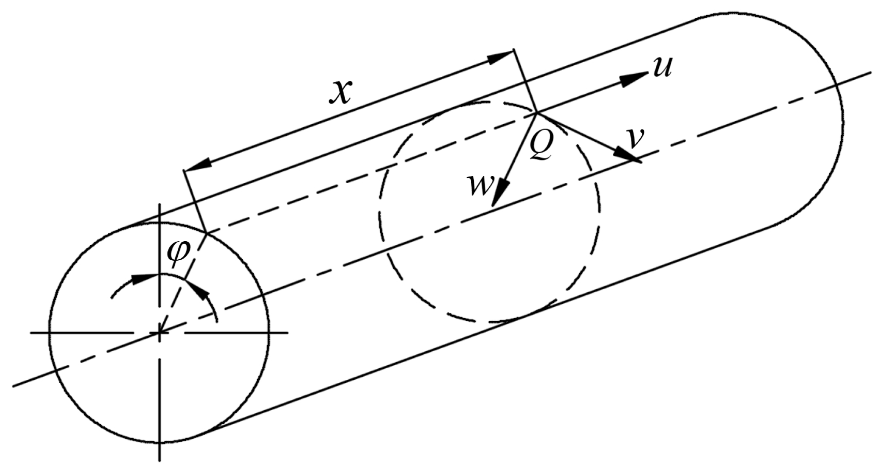
In general, the underwater glider pressure hull is a thin shell structure for which the ratio of maximum thickness and radius of curvature is not greater than 1 / 20 . The object of study in this paper is a typical cylindrical shell with equally spaced ribs. To facilitate the study, a cylindrical coordinate system is required in the establishment of the pressure hull model, as shown in Figure 2. The position of any point Q ( x , φ ) on the middle surface of the pressure hull can be expressed in two coordinates x and φ . There are some concepts defined as follows. A straight line made when φ is constant and x varies is called the mainline. A circle made when x is constant and φ varies is called the subline. The section resulting from cutting the shell with a plane parallel to the subline is called the cross-section. The section resulting from cutting the shell with a plane through the central axis is called the longitudinal section. A rectangular coordinates system in space is established at point Q , where u denotes the axial displacement of the point, v denotes the circumferential displacement of the point, and w denotes the radial displacement of the point.
The ring rib cylindrical shell structure parameters are defined as shown in Figure 3. The reinforcement ribs include both ordinary ribs and oversized ribs. The ordinary ribs are more commonly used. Without special remarks, all ribs mentioned in this paper are ordinary ribs. L is the length of the pressure hull, R is the radius of the pressure hull, t is the thickness of the pressure hull, h 1 is the height of the ordinary rib, b 1 is the width of the ordinary rib, l is the spacing between the ordinary ribs, h 2 is the height of the oversized rib, and b 2 is the width of the oversized rib.

3.2. Calculation Model of Deformation under External Pressure

For the cylindrical pressure shell with equally spaced ribs, the key to the deformation calculation of the pressure hull is to obtain the radial displacement of the shell. The following paragraphs of this paper will derive the radial displacement calculation model.
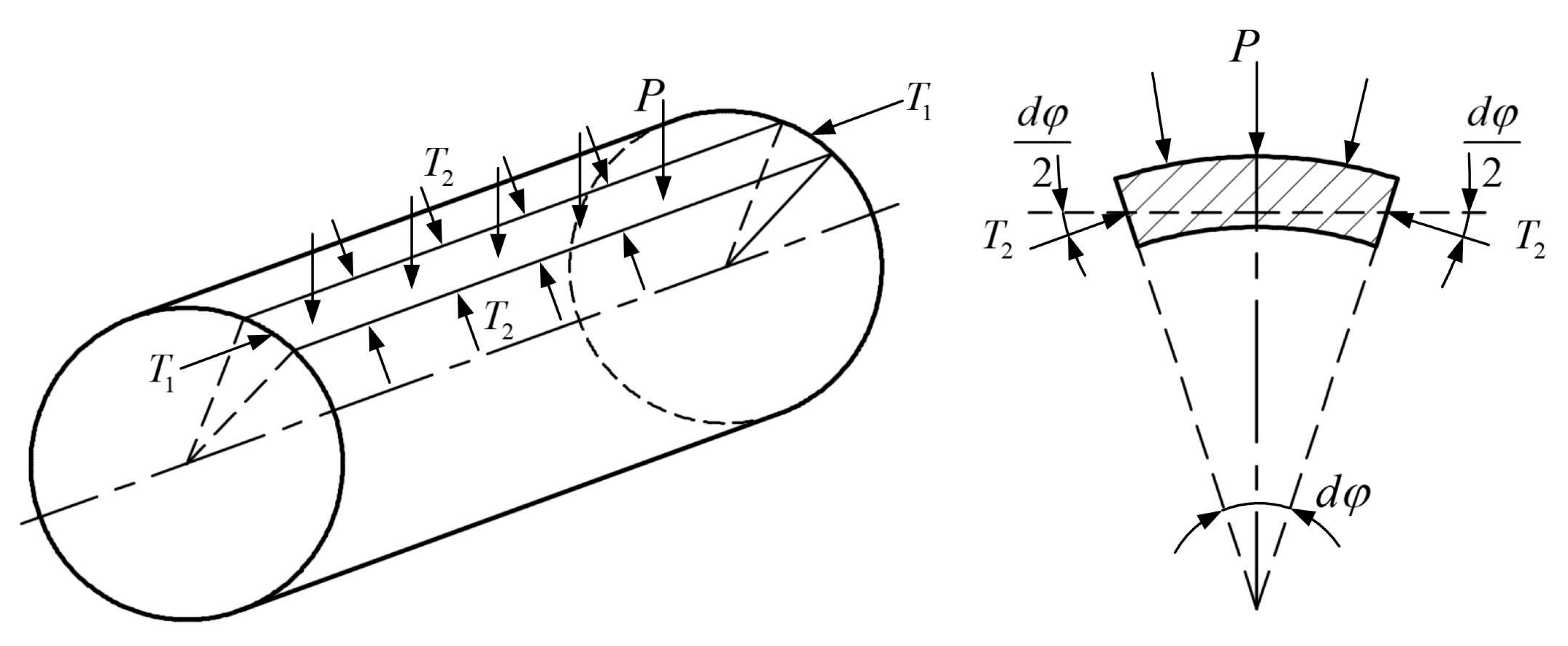
A slicing unit of length d s = R d φ = 1 is taken out of the cylindrical shell cross-section as shown in Figure 4. Since the external pressure is uniformly distributed on the outer surface of the cylindrical shell, the stresses and displacements are the same on each slicing unit. Therefore, the stresses on the entire cylindrical shell can be obtained by studying a single slicing unit only.
The forces on each slicing unit are define as follows: P is the water pressure on the external surface, T 1 is the squeezing force in the axial direction, and T 2 is the interaction force between each slicing unit. T 1 can be expressed as:
T 1 = π R 2 P 2 π R = P R 2
The combined force direction of T 2 is the same as the direction of P . Then, the force perpendicular to the slicing unit and pointing to the direction of curvature center T p can be expressed as:
T p = P + 2 T 2 sin d φ 2 P + T 2 d φ = P + T 2 R
By Kirchhoff’s assumption, the thin shell structure subjected to uniform external pressure is not required to consider the effect of tangential stress, which means that the thin shell can considered to be in a state of biaxial stress [23]. Then, the linear strain in the direction of the subline tangential on the middle surface of the shell ε 2 0 can be expressed as:
ε 2 0 = 1 E ( σ 2 0 μ σ 1 0 )
where E is the modulus of elasticity of the shell material, μ is the Poisson’s ratio of the shell material, σ 1 0 is the normal stress in the direction of the mainline on the middle surface, and σ 2 0 is the normal stress in the direction of the subline on the middle surface. Substituting T 1 = σ 1 0 t and T 2 = σ 2 0 t into Equation (6), the following equation can be obtained.
ε 2 0 = 1 E t ( T 2 μ T 1 )
By the geometric relations, we can also obtain the following equation.
ε 2 0 = 2 π ( R w ) 2 π R 2 π R = w R
where w is the radial displacement. Substituting Equations (4) and (7) into Equation (8), we can obtain the expression as follows:
T 2 = E t w R μ 2 P R
The bending differential equation for the slicing unit is shown as:
D w ( 4 ) + T 1 w ( 2 ) = P + T 2 R
where D is the bending rigidity of the slicing unit. Additionally, D can be expressed as:
D = E t 3 12 ( 1 μ 2 )
Substituting Equations (4) and (9) into Equation (10), we can obtain the expression as follows:
D w ( 4 ) + P R 2 w ( 2 ) + E t R 2 w = P ( 1 μ 2 )
The above equation is a fourth-order non-homogeneous differential equation whose general solution can be expressed as the general solution of the homogeneous differential equation plus a particular solution of the non- homogeneous equation. It can be expressed as follows:
w = w 0 + w 1 = P R 2 E t ( 1 1 2 μ ) + C 1 cosh α 1 x cos α 2 x + C 2 sinh α 1 x cos α 2 x + C 3 cosh α 1 x sin α 2 x + C 4 sinh α 1 x sin α 2 x
where C 1 , C 2 , C 3 , and C 4 are the integration constants which are determined by the boundary conditions of the pressure hull. Additionally, α 1 , α 2 can be expressed as:
{ α 1 = 3 ( 1 μ 2 ) R 2 t 2 4 1 λ α 2 = 3 ( 1 μ 2 ) R 2 t 2 4 1 + λ λ = 1 2 3 ( 1 μ 2 ) P R 2 E t 2
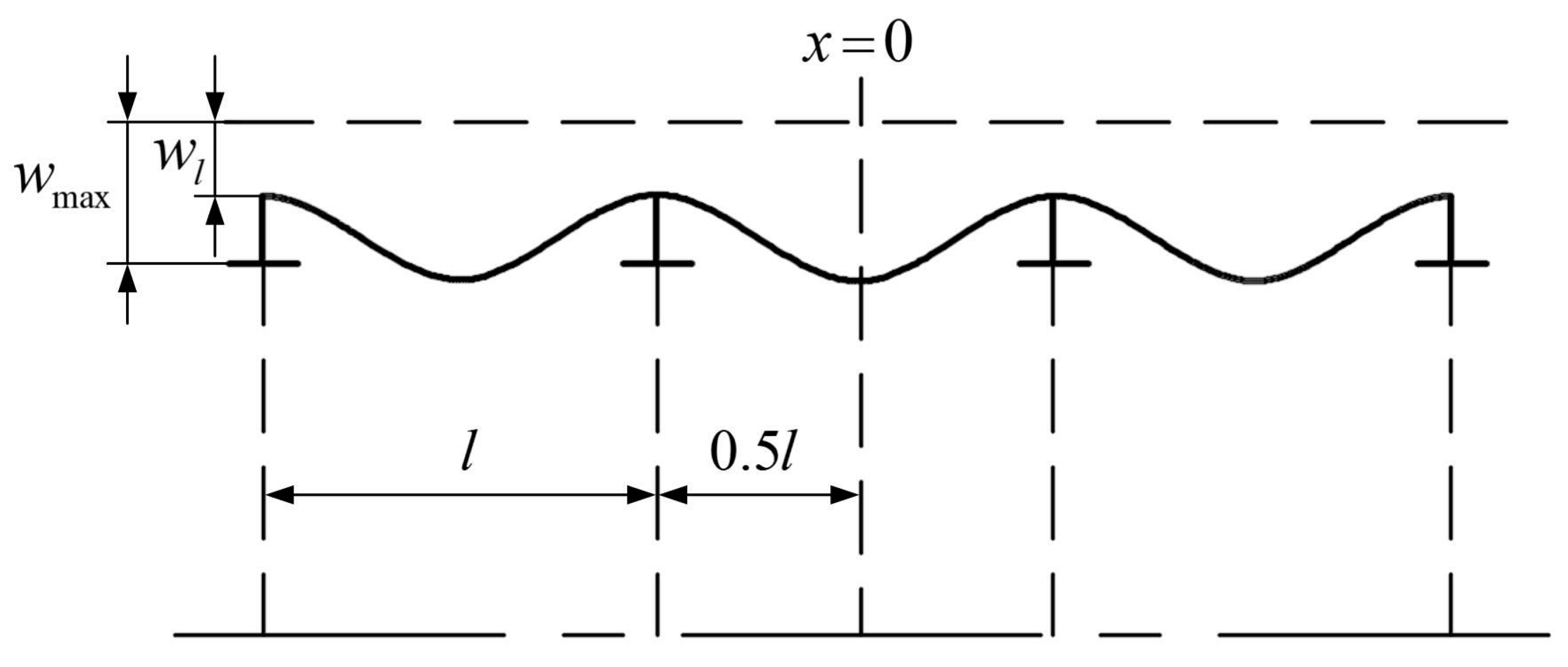
The cylindrical pressure hull is arranged with ribs, and the ribs will have a supporting effect on the shell. When the water pressure acts uniformly on the surface of the cylindrical shell, the deformation is shown in Figure 5. Additionally, the deformation is symmetrical to the central axis.
At the midpoint of the span rib, the displacement has a maximum value w m a x , and at the rib, the displacement has a minimum value w l . Establishing the coordinate system at the midpoint of the span rib, the displacement of the mainline in the radial direction is an even function about x. In Equation (13), C 2 and C 3 are odd function terms, then C 2 = C 3 = 0 , w x = 0 = w x = ± 0.5 l , and Equation (13) can be simplified as:
w = w 0 + w 1 = P R 2 E t ( 1 1 2 μ ) + C 1 cosh α 1 x cos α 2 x + C 4 sinh α 1 x sin α 2 x
Here, we have obtained a general solution for the bending deformation of a general ring-ribbed cylindrical shell. Thus, we have obtained the expression for the radial displacement w of the pressure hull. In addition, the axial displacement between two ribs after compression deformation of the pressure hull can be expressed as:
l = l l = P R 0 2 E [ R 0 2 ( R 0 2 t ) 2 ] ( 1 2 μ ) l
where l is the length of the section of the shell after deformation, l is the difference in axial displacement before and after deformation. Then, this volume of the pressure hull between the two ribs after deformation can be expressed as:
V l = l l 0.5 l 0.5 l π ( R 0 w ) 2 d x
Considering that the actual deformation is small and the deformation is symmetric, the above equation can be simplified as:
{ V l = l ( R 0 w e ) 2 w e = w x = 0 + w x = 0.5 l 2 w x = 0.5 l = P R 0 2 E t ( 0.85 0.85 ε 1 ) w x = 0 = P R 0 2 E t ( 0.85 ε 4 )
Then, the volume deformation of the entire pressure hull can be expressed as:
Δ V P = L l ( V l V l ) = L l [ l π R 0 2 l π ( R 0 w e ) 2 ] = L π R 0 2 L π R 0 2 { 1 P R 0 2 E [ R 0 2 ( R 0 t ) 2 ] ( 1 2 μ ) } [ 1 P R 0 2 E t ( 1.7 0.85 ε 1 ε 4 ) ] 2 = L π R 0 2 ( 1 κ 1 κ 2 ) = L π R 0 2 κ
Here, mark κ as the compression rate of the pressure shell, which is related to the structural parameters and materials of the pressure shell. The greater the compression rate κ , the greater the deformation.

3.3. Calculation Model of Deformation Casued by Temperature Reduction

When the underwater glider dives and floats, its drainage volume will change due to the change in seawater temperature, which is called the drainage volume temperature deformation Δ V T . Additionally, it can be expressed as:
Δ V T = 3 α v T V 0 = ζ V 0
where α v is the coefficient of thermal expansion of the material and V 0 is the initial volume. Here, ζ is defined as the temperature difference deformation coefficient and ζ = 3 α v T .
In summary, the total deformation of the pressure shell of the underwater glider in marine environment V d can be expressed as:
V d = V T + V P = ( ζ + κ ) V 0

3.4. Calculation Model of the Pressure Hull Mass

In this paper, the mass of pressure shell m o p is composed of three parts: the shell plate mass m s , the ordinary ribs mass m r 1 , and the oversized ribs mass m r 2 . The total number of the ribs is L / l 1 , the number of the oversized ribs is y , and the number of ordinary ribs is L / l y 1 . The mass of the pressure hull can be expressed as:
{ m o p = m s + m r 1 + m r 2 m s = ρ π L [ R 0 2 ( R 0 t ) 2 ] m r 1 = ρ π b 1 [ ( R 0 t ) 2 ( R 0 t h 1 ) 2 ] ( L l y 1 ) m r 2 = ρ π b 2 y [ ( R 0 t ) 2 ( R 0 t h 2 ) 2 ]

4. Strength and Stability Constraint Models

4.1. Strength Calculation Model for the Pressure Hull

As shown in Figure 5, the maximum stress of the pressure hull may occur at the midpoint across the ribs and also at the ribs. Therefore, it is necessary to calculate the stresses and displacements at these special positions.

4.1.1. Axial Normal Stress on the Shell Plate

The axial normal stress on the shell plate σ 1 is composed of two parts. One part is generated by the axial pressure T 1 and the other part is generated by the bending stress, as shown in Figure 4. It can be expressed as:
σ 1 = P R 2 t ± 6 D w t 2
Substituting x = 0.5 l and x = 0 into Equation (23), we can obtain the maximum axial normal stress on the shell plate at the midpoint across the ribs σ 1 m and the axial normal stress on the shell plate at the ribs σ 1 r . Additionally, they can be expressed as:
{ σ 1 m = ( σ 1 ) x = 0 = P R t ( 0.5 ± ε 3 ) σ 1 r = ( σ 1 ) x = 0.5 l = P R t ( 0.56 ε 2 )

4.1.2. Circumferential Stress on the Shell Plate

For the thin shell structures, the circumferential stress on the shell plate σ 2 can be expressed as:
σ 2 = E ε 2 0 + μ σ 1 = E w R + μ σ 1
Substituting Equations (23) and (24) into Equation (25), we can obtain the circumferential stress on the shell plate across the midpoint of the rib σ 2 m , the circumferential stress on the middle surface of the shell plate at the midpoint across the rib σ 2 0 , and the circumferential stress in the shell plate at the rib σ 2 r , as shown in Equation (26).
{ σ 2 m = P R t ( 1 ε 4 ± μ ε 3 ) σ 2 r = P R t ( 1 0.5 μ ) ( 1 ε 1 ) + μ σ 1 r σ 2 0 = P R t ( 1 ε 4 )

4.1.3. Axial Normal Stress on the Ribs

The axial positive stress on the ribs σ f can be expressed as Equation (27).
σ f = E w l R = σ 2 r μ σ 1 r = P R t ( 1 0.5 μ ) ( 1 ε 1 )
Equations (24), (26) and (27) can be written in the following unified form.
σ 2 0 = K 2 0 P R t           σ 1 r = K 1 r P R t           σ f = K f P R t
{ K 2 0 = 1 F 4 ( u 1 , u 2 ) 1 + β F 1 ( u 1 , u 2 ) K 1 r = 0.56 + F 2 ( u 1 , u 2 ) 1 + β F 1 ( u 1 , u 2 ) K f = ( 1 0.5 μ ) F 1 ( u 1 , u 2 ) 1 + β F 1 ( u 1 , u 2 )
where β = l t / A , K 2 0 , K 1 r , and K f are the stress coefficients corresponding to the above stresses, respectively.

4.1.4. Strength Constraint Conditions

With reference to the strength calibration equations of the China Classification Society (CCS) specification [24], we select σ 2 0 , σ 1 r , and σ f as the parameters of the strength constraint equation. In this paper, the strength constraint conditions can be expressed as:
{ σ 2 0 = P R t ( 1 ε 4 ) 0.85 σ s σ 1 r = P R t ( 0.56 ε 2 ) 1.15 σ s σ f = P R t ( 1 0.5 μ ) ( 1 ε 1 ) 0.6 σ s

4.2. Stability Calculation Model for the Pressure Hull

The instability of pressure hull is closely related to its materials, structures, sizes, loads and other factors. When the rigidity of the ring rib is greater than the critical rigidity of the whole cabin, the local instability will occur with the increase in uniform external pressure, which is called shell plate instability. Conversely, the general instability of pressure hull will occur and is defined as rib instability.
Based on the shape of the pressure hull rib instability, the coordinate system is established as shown in Figure 6. In this paper, the Ritz energy method is used to derive the stability model of the pressure hull [25]. The total potential energy Π of the pressure hull is the sum of the strain energy U of the pressure hull and the work W of the external force. The strain energy of the pressure hull includes the strain energy of the shell plate and the strain energy of the ribs. The strain energy of the shell plate is composed of the bending strain energy of the shell plate and the middle surface strain energy of the shell plate. The external force work includes longitudinal force work and transverse force work.
In the case of rib instability, the two ends of the shell can be considered as freely supported on the rigid support, and the displacement in the tangential direction v and the displacement in the radial direction w at both ends are zero. The displacement function can be expressed as:
{ u = A sin n φ cos m π x / L v = B sin n φ cos m π x / L w = C cos n φ sin m π x / L
where m is the number of half waves on the longitudinal profile at the time of instability, n is the number of whole waves on the cross-section at the time of instability. A , B and C are the constants to be determined.

4.2.1. Strain Energy of Pressure Hull

In elastic mechanics [26], the strain energy can be expressed in Equation (32).
U = 1 2 ( σ x ε x + σ y ε y + σ z ε z + τ x y γ x y + τ y z γ y z + τ z x γ z x )
  • According to Kirchhoff’s assumption [23], there is the expression γ y z = γ z x = σ z = 0 . The shell is in a bi-directional stress condition, and its stress–strain relationship as shown in Equation (33).
    { σ x = E 1 μ 2 ( ε x + μ ε y ) σ y = E 1 μ 2 ( ε y + μ ε x ) τ x y = E 2 ( 1 μ ) γ x y
Substituting Equation (33) into Equation (32), the strain energy expression of the ring rib cylindrical shell as shown in Equation (34).
U = E 2 ( 1 μ 2 ) [ ε 1 2 + ε 2 2 + 2 μ ε 1 ε 2 + 1 2 ( 1 μ ) γ 2 ] R d x d φ
Substituting Equations (A8), (A11) and (A12) from the Appendix A into Equation (34), integrating from z = 0.5 t to  z = 0.5 t , the following equation is obtained.
{ U = U 1 + U 2 U 1 = D 2 [ ( χ 1 + χ 2 ) 2 2 ( 1 μ ) ( χ 1 χ 2 χ 12 2 ) ] R d x d φ U 2 = E t 2 ( 1 μ ) { ( ε 1 0 + ε 2 0 ) 2 2 ( 1 μ ) [ ε 1 0 ε 2 0 1 4 ( γ 0 ) 2 ] } R d x d φ
where D = E t 3 / [ 12 ( 1 μ 2 ) ] . U 1 is called the bending strain energy which contains three variables χ 1 , χ 2 , and χ 12 . U 2 is called the middle surface strain energy which contains three variables ε 1 , ε 2 , and γ 0 .
The strain energy of the rib can be considered as the sum of strain energy of several individual ribs. The strain energy for a single rib can be expressed as:
( U 3 i ) x = i l = E I 2 0 2 π ( ε 2 0 ) 2 R d φ + E I 2 0 2 π χ 2 2 R d φ
The second term of the above equation is the bending strain energy, which is much larger than the compression strain energy represented by the first term of the above equation. Then, the above equation can be simplified as:
( U 3 i ) x = i l = E I 2 0 2 π χ 2 2 R d φ
As shown in the Figure A1 from the Appendix A, we substitute Equation (A6) into Equation (37), it can be obtained as:
( U 3 i ) x = i l = E I π 2 R 3 ( n 2 1 ) 2 C 2 sin 2 m π x L
The total number of ribs is L / l 1 , so the total rib strain energy is shown as:
U 3 = i = 1 L / l 1 ( V 3 i ) x = i l = E I π 2 R 3 ( n 2 1 ) 2 C 2 i = 1 L / l 1 sin 2 i m π l L = π L 4 R E I R 2 L ( n 2 1 ) C 2

4.2.2. External Work on Pressure Hull

Define a slicing unit with length d x , arc length d s = R d φ , and thickness t , which is called A B C D . As shown in Figure 7a, in the equilibrium state before destabilization, the external forces are the water pressure on the external surface P , the axial squeezing force on the transverse profile T 1 , and the circumferential squeezing force on the longitudinal profile T 2 . For the slicing unit ABCD, when the shell is destabilized, the slicing unit will have a displacement variation, and the above mentioned three forces will perform work on the unit.
As shown in Figure 7b, the longitudinal force is the axial squeezing force T 1 . When instability occurs in the shell, an angle of rotation w / x is generated on the mainline, then its work can be expressed as Equation (40).
d W 1 = 1 2 ( T 1 R d φ w x d x ) · w x = 1 2 T 1 ( w x ) 2 R d φ d x
Substituting Equation (31) into Equation (40), the expression for the work performed by the longitudinal force is obtained as Equation (41).
W 1 = T 1 2 0 L 0 2 π ( w x ) 2 R d φ d x = π L 4 R T 1 α 2 m 2 C 2
As shown in Figure 7c, the transverse forces include the water pressure on the outer surface P and the circumferential squeezing force on the longitudinal profile T 2 . When instability occurs in the shell, the B C and A D sides yield a turning angle χ 2 R d φ , then the work performed can be expressed as:
d W 2 = 1 2 T 2 χ 2 w R d φ d x
After integration, the work performed by the transverse forces can be expressed as:
W 2 = T 2 2 0 1 0 2 π χ 2 w R d φ d x = π L 4 R T 2 ( n 2 1 ) C 2

4.2.3. Stability Constraint Conditions

The sum of the strain energy U and the external work W of the pressure shell is obtained above. Then, the total potential energy of the pressure shell Π can be expressed as:
Π = U 1 + U 2 + U 3 + W 1 + W 2 = π L 4 R D R 2 { 2 ( 1 μ ) m 2 α 2 B 2 + 4 ( 1 μ ) m 2 α 2 n B C + [ ( m 2 α 2 + n 2 1 ) 2 + 2 ( 1 μ ) m 2 α 2 ] C 2 } + π L 4 R E t ( 1 μ 2 ) { A 2 [ m 2 α 2 + 1 2 ( 1 μ ) n 2 ] + ( 1 + μ ) m n α A B + [ n 2 + 1 2 ( 1 μ ) m 2 α 2 ] B 2 + 2 n B C + 2 μ m α A C + C 2 } + π L 4 R E I R 2 L ( n 2 1 ) C 2 + π L 4 R T 1 α 2 m 2 C 2 + π L 4 R T 2 ( n 2 1 ) C 2
Omitting the higher order terms, Equation (44) can be simplified as:
Π = π L 4 R { [ D R 2 ( m 2 α 2 + n 2 1 ) 2 + E t ( 1 μ 2 ) + E I R 2 L ( n 2 1 ) T 1 m 2 α 2 T 2 ( n 2 1 ) ] C 2 + E t ( 1 μ 2 ) [ n 2 + 1 2 ( 1 μ ) m 2 α 2 ] B 2 + E t ( 1 μ 2 ) [ m 2 α 2 + 1 2 ( 1 μ ) n 2 ] A 2 + E t ( 1 μ 2 ) [ 2 n B C + 2 μ m α A C + ( 1 μ ) m n α A B ] }
The critical load needs to satisfy Equation (46).
Π A = 0 ,     Π B = 0 ,     Π C = 0
Then, the following equation can be obtained.
( a 11 a 12 a 13 a 21 a 22 a 23 a 31 a 32 a 33 ) ( A B C )
{ a 11 = Λ [ 2 m 2 α 2 + ( 1 μ ) n 2 ] a 12 = a 21 = Λ ( 1 + μ ) m n α a 13 = a 31 = 2 Λ μ m α a 22 = Λ [ ( 1 μ ) m 2 α 2 + 2 n 2 ] a 23 = a 32 = 2 Λ n a 33 = 2 [ D R 2 ( m 2 α 2 + n 2 1 ) 2 + Λ + E I R 2 L ( n 2 1 ) 2 T 1 m 2 α 2 T 2 ( n 2 1 ) ]
where Λ = E t 3 / [ 12 ( 1 μ 2 ) ] . If we make Euqations (47) holds and there are solutions of A , B , and C that are not zero, then the following equation must be satisfied.
| a 11 a 12 a 13 a 21 a 22 a 23 a 31 a 32 a 33 | = 0
Substituting Equation (48) into the above determinant, the theoretical stability formula of the cylindrical shell with ribs under external pressure can be expressed as:
T 1 m 2 α 2 + T 2 ( n 2 1 ) = D R 2 ( m 2 α 2 + n 2 1 ) 2 + E t m 4 α 4 ( m 2 α 2 + n 2 ) + E I R 2 L ( n 2 1 ) 2
where T 1 P R / 2 , T 2 P R , and substituted into the above equation, the theoretical critical pressure of instability of the cylindrical shell with ribs can be expressed as:
P E 2 = 1 n 2 1 + 0.5 m 2 α 2 [ D R 3 ( n 2 1 + m 2 α 2 ) 2 + E t R m 4 α 4 ( m 2 α 2 + n 2 ) 2 + E I R 3 L ( n 2 1 ) 2 ]
For the conventional pressure shell of commonly used materials, the above equation has the minimum value when m = 1 . Therefore, the above equation can be simplified as:
{ P E 2 = 1 n 2 1 + 0.5 α 2 [ D R 3 ( n 2 1 + α 2 ) 2 + E t R α 4 ( α 2 + n 2 ) 2 + E I R 3 L ( n 2 1 ) 2 ] I = I 0 + l t 3 12 + l t A l t + A ( Z 0 + t 2 ) 2
Make n = 2 , 3 , 4 ,   respectively , and substitute into the calculation. The minimum value is the theoretical instability critical pressure.
When the rib rigidity is greater than the critical rigidity of the whole shell, the first possible instability of the shell plate may occur at this time. The instability length at this time is the rib spacing l , and there is no rib in the spacing. Then, make I = 0 , and thus, we can obtain the theoretical critical pressure of the shell plate instability of the cylindrical shell with ribs, as shown in Equation (53).
P E 1 = 1 n 2 1 + 0.5 α 2 [ D R 3 ( n 2 1 + α 2 ) 2 + E t R α 4 ( α 2 + n 2 ) 2 ]
The stability of the pressure shell with oversized rib needs special discussion. We may define the moment of inertia of the oversized rib of the pressure shell as J , and we define the distance from the left end of the compartment as a. The oversized rib can be regarded as a combination of ordinary rib overlapping a special rib. The moment of inertia can be expressed as J = I + J*. The strain energy of this oversized rib can be expressed as:
U 4 = E J * 2 0 2 π     ( χ 2 ) x = a 2 R d φ = π E ( J I ) 2 R 3 ( n 2 1 ) 2 C 2 sin 2 π a L
Therefore, the total potential energy of pressure shell with oversized ribs Π can be expressed as Π = U 1 + U 2 + U 3 + U 4 + W 1 + W 2 . Then, the overall instability theoretical critical pressure shell containing oversized ribs can be expressed as:
P E 3 = 1 n 2 1 + 0.5 α 2 { D R 3 ( n 2 1 + α 2 ) 2 + E t α 4 R ( n 2 + α 2 ) 2 + E ( n 2 1 ) 2 R 3 [ L l + 2 ( J I ) L sin 2 π a L ] }
The actual instability pressure of the pressure hull is smaller than the theoretical instability critical pressure obtained above, there are two main reasons for the difference: Firstly, solving the theoretical instability critical pressure is based on the material is linearly elastic, the actual instability of the pressure-resistant shell has exceeded the elastic limit. Secondly, the theoretical instability critical pressure is solved by considering the structure as ideal cylindrical shape, while in reality, the structure will have initial defects. Therefore, the theoretical instability critical pressure needs to be corrected. We define P c r 1 , P c r 2 and P c r 3 as the corrected critical pressure for the shell plate, ribs and overall instability, respectively. In this paper, the stability constraint conditions can be expressed as:
{ P c r 1 P P c r 2 1.2 P P c r 3 1.3 P

5. Optimization Process and Results

The pre-assigned design parameters are defined as follows. The total length of the pressure hull L is 1440 m, the radius R is 135 mm, the mass m 0 is 27.571 kg, the maximum working depth is 1000 m, the maximum external pressure is 10 MPa, and the material of the pressure hull is chosen from aluminum alloy 7075-T6, the material properties of which are shown in Table 2.
In this paper, there are six parameters of the pressure hull to be optimized, which are the thickness of shell plate t , ordinary ribs spacing l , ordinary ribs width b 1 , ordinary ribs height h 1 , oversized ribs width b 2 , and oversized ribs height h 2 .

5.1. Optimization Function

The underwater glider developed by HUST has two modes for gliding navigation: normal gliding mode and constant speed gliding mode. The normal gliding mode is similar to the gliding motion of regular gliders, and it is used for large-scale ocean observation. The constant speed gliding mode is a special mode to ensure the observation of the vertical water layer uniformly, and the net buoyancy will be actively adjusted in real time with the environmental influence during ascend or descent to maintain the constant gliding speed. The normal gliding mode is more commonly used when actually executing observation tasks. In Equation (3), the ω v is related to the energy consumption of the buoyancy adjustment unit. To facilitate the determination of the coefficients ω v of the optimization objective, the normal gliding mode is selected for the analysis.
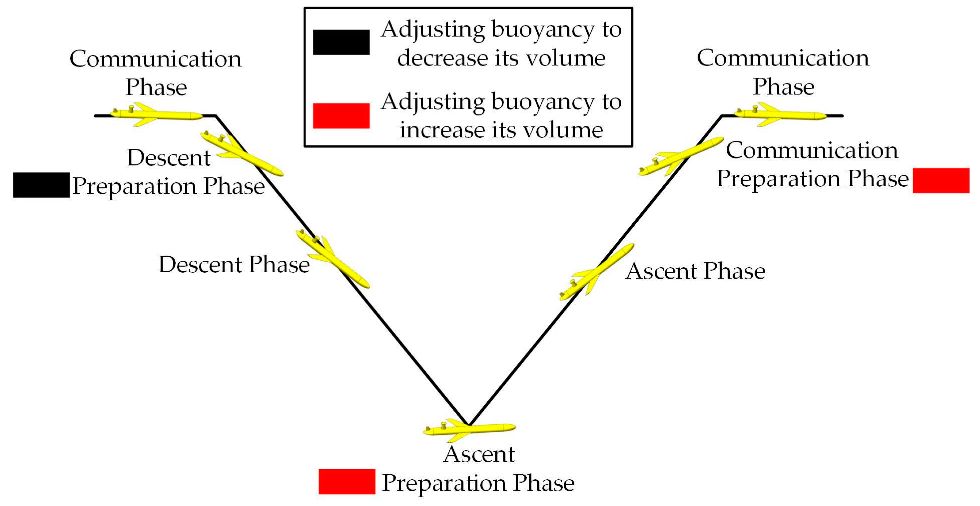
A complete gliding profile with the various working phases of the glider in the normal gliding mode is shown in Figure 8. In particular, the buoyancy adjustment unit was operated during the descent preparation phase, the ascent preparation phase, and the communication preparation phase.
In the descent preparation phase, the low-pressure pump is activated to transfer the oil from the external oil bladder to the internal tank, which makes the underwater glider drainage volume decrease. The volume change in this phase is noted as B d . The measured low-pressure pump power P d is 6 Watts, and its quantity Q d is 150 mL/min. In the ascent preparation phase, the high-pressure pump is activated to transfer the oil from the internal tank to the external oil bladder, which makes the underwater glider drainage volume increase. The volume change in this phase is noted as B a . The measured high-pressure pump power P a is 96 Watts at 1000 m depth, and its quantity Q a is 220 mL/min. In the communication preparation phase, the air pump is activated and the air valve is opened to inflate the external air bladder, which makes the underwater drainage volume increase. The volume change in this phase is noted as B c . The measured pneumatic components power P c is 1 Watts, and its quantity Q c is 850 mL/min. Then, the energy consumption of the buoyancy adjustment unit for one gliding profile at 1000 m depth E b u o can be expressed as:
E b u o = E d + E a + E c = P d B d Q d + P a B a Q a + P c B c Q c
The increase in shell deformation caused by the optimization of the pressure hull can affect the values of ∆Bd and B a . Therefore, we substitute the test measurements of each parameter into Equation (57), and ω v can be expressed as:
ω v = P d Q d + P a Q a = 28.58   J / m L
The underwater glider in this paper is equipped with a lithium battery. Specifically, the energy density of the lithium-thionyl chloride battery D b can reach 600 Wh/kg. After the optimization, the carrying space brought by the weight reduction cannot be fully used to carry the battery. The reason is as follows: the batteries are not uniformly distributed on the underwater glider, and if all the weight from the weight reduction is used to increase the batteries, it will inevitably disrupt the attitude balance of the underwater glider. Additionally, it is necessary to reserve weight for the weight blocks which balance the attitude of the underwater glider. Here, the space conversion factor K s c f is defined to represent the relationship between the increased space and the increased batteries, and the value of K s c f here is 0.9. In this paper, the maximum number of gliding profiles at 1000 m depth N 1000 m that can be accomplished by the underwater glider is designed to be 1000. Thus, the ω m in Equation (3) can be calculated by Equation (59).
ω m = D b K s c f N 1000 m = 1.944   J / g
From the analysis in Section 3 and Section 4, where Δ m can be expressed as Equation (22), Δ V d can be expressed as Equation (21), ωm can be expressed as Equation (59), and ω v can be expressed as Equation (58). The optimization constraints include strength constraints and stability constraints, which are given by Equations (30) and (56), respectively. In addition, an additional safety factor k s = 1.2 is added to the constraints in this paper. Additionally, the value ranges of the structural parameters need to be large enough to ensure the validity of the optimization results. In summary, the optimized mathematical models of the pressure hull are shown in the following equations.
{ m i n E I F = ( ω m m + ω v V d ) s . t . k s σ 2 0 0.85 σ s 0 k s σ 1 1.15 σ s 0 k s σ f 0.6 σ s 0 k s P P c r 1 0 1.2 k s P P c r 2 0 1.3 k s P P c r 3 0 3 t 8 30 l 200 5 b 1 30 5 h 1 15 20 b 2 80 10 h 2 30

5.2. Optimization Algorithm

This optimization problem involves six structural parameters of the pressure hull and six nonlinear constraint functions, which is a relatively complex optimization problem. Selecting a suitable optimization problem cannot merely improve the optimization efficiency, but it can also enhance the accuracy of the optimization results. To solve this optimization problem, a hybrid genetic simulated annealing algorithm (HGSAA) is adopted in this paper, which combines the global optimization ability of genetic algorithm (GA) and the local optimization ability of simulated annealing algorithm (SA).
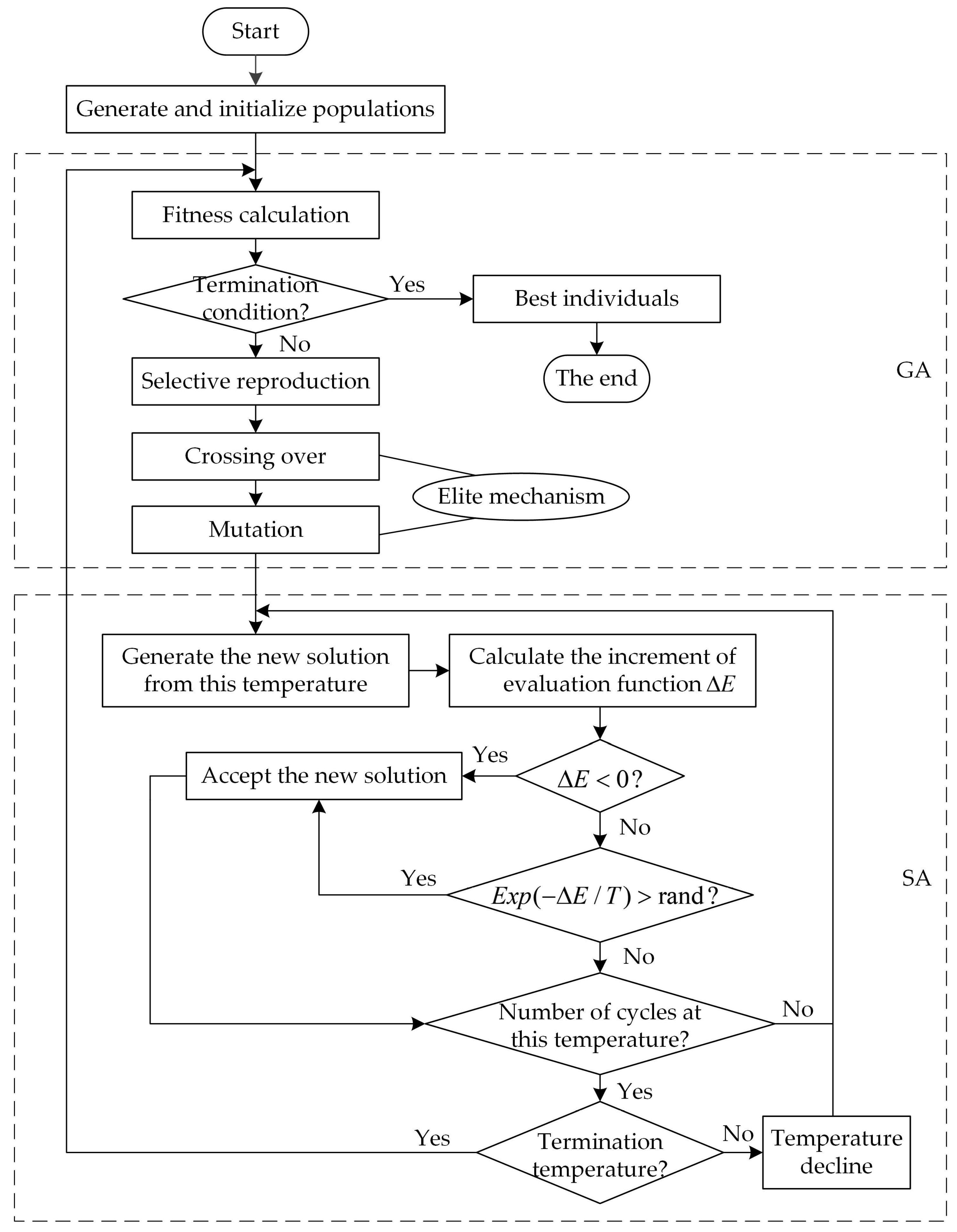
In the HGSAA algorithm flow, the solutions derived from the SA are used as the initial population for the GA. The elite mechanism is adopted in the crossover and mutation operations of the GA, and then the obtained solutions are used as the initial population of the SA. At higher temperatures, the algorithm exhibits a strong global search capability and it is perceived as a rough search for the population. At lower temperatures, the algorithm exhibits a strong local search capability and it is perceived as a thorough search for the population. The flow chart of HGSAA is shown in Figure 9. Additionally, the optimization process of HGSAA is described as follows.
Step 1: Assign values and initialize the population P ( k ) . The parameters are assigned as follows: population size N P is 100, crossover probability P c is 0.9, variation probability P m is 0.01, evolutionary generation G is 500, initial temperature t 0 is 200 , termination temperature t f is 0.01, Markov chain length L M is 600, and temperature decline coefficient α t is 0.95.
Step 2: Calculate the fitness of each individual in the current population P ( k ) and determine whether the termination condition is satisfied. The termination conditions are the number of evolutionary generations G , the maximum time of calculation T m a x , the number of consecutive non-evolutionary generations N c n , and the consecutive non-evolutionary time T c n , and one of the four conditions is satisfied, which means the current result is output as the best individual. Otherwise, Step 3 will be executed next.
Step 3: Selective reproduction. The selection operator is used for the population to select superior individuals to be inherited into the next generation population under certain rules and methods using fitness as a criterion.
Step 4: Crossing over. The individuals in population P ( k ) are crossed over to obtain population P ( k ) with the elite mechanism. The elite mechanism compares the fitness of the new individuals after crossing over with that of the old individuals. If the fitness of the new individuals is better than that of the old ones, then these new individuals will be retained in P ( k ) .
Step 5: Mutation operation. The population P ( k ) is obtained after mutation of individuals in P ( k ) , also with the elite mechanism.
Step 6: The elite individuals in population P ( k ) will enter the SA process while a new solution is generated based on the current temperature and these individuals.
Step 7: Based on the evaluation function to determine whether the new solution is accepted or not. If E < 0 , then the new solution is accepted as the current solution; otherwise, the new solution is accepted as the current solution with probability exp ( E / T ) .
Step 8: This step determines whether the search is sufficient at this temperature t k . If it has not been sufficiently searched, then skip to Step 6. If it has been sufficient searched, Step 9 will be executed next.
Step 9: Determine whether the termination temperature is reached. If the termination temperature is not reached, the temperature will be declined in a certain way, with the rule as t k = α t t k 1 , then skip to Step 6. If the termination temperature is reached, then skip to Step 2.

5.3. Analysis Optimization Results

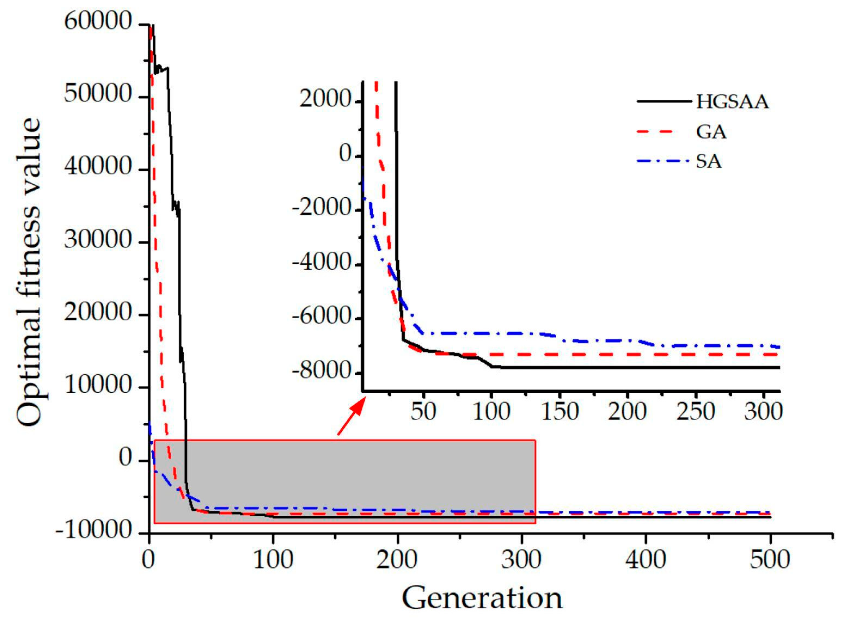
In this part, we will adopt HGSAA, GA, and SA to optimize the pressure hull, respectively. The fitness evolutionary curves of HGSAA, GA, and SA are shown in Figure 10.
As shown in Figure 10, the global search ability of the GA is stronger, and the optimal solution domain can be found quickly within a smaller number of iterations, but the thorough search ability of the optimal solution domain is weaker. Its final solution is inferior to that of the HGSAA. The SA has a strong local search capability, but its global search capability relies on the initial temperature t 0 and temperature decline factor α t , and it has the disadvantage of low efficiency. The final solution is also inferior to that of the HGSAA. In brief, when the energy consumption improvement E I F is the optimization objective, the comprehensive optimization effect of HGSAA is better than GA and SA.
The optimization results of HGSAA and the comparison of the original parameters are shown in Table 3. Compared with the original structural parameters, the optimized structural parameters show a decrease in the values of t , l , b 1 and h 2 , along with increased values of h 1 , b 2 . In the HGSAA optimization results, the increase in h1 is greater than the decrease in b 1 and the decreae in l , which makes the ribs rigidity increase and helps to increase the critical pressure of rib instability. An appropriate decrease in t can simultaneously reduce the mass of pressure shell and increase the deformation of pressure shell. Decreasing the h 2 and increasing the b 2 will increase the rigidity of the ribs. The above HGSAA optimization results are consistent with the trend of theoretical analysis.
The HGSAA optimization results of the performance parameters related to the pressure hull are shown in Table 4. The weight of the pressure hull m is reduced from 27,571 g to 24,877 g, an increase of 9.77%. The deformation of the pressure hull at 1000 m V d _ 1000 increased from 521 mL to 603 mL, an increase of 15.74%. The V d _ 1000 includes two parts: the first part is the volume deformation caused by the external pressure of seawater Δ V P _ 1000 , and the second part is the volume deformation caused by the lowering of seawater temperature Δ V T _ 1000 . Δ V T _ 1000 is easy to understand: as the temperature decreases, the shell structure contraction occurs, the shell volume appears to be reduced, which is mainly related to the material characteristics of the pressure hull. Δ V P _ 1000 is closely related to the parameters of the pressure hull. By rational optimization of the cylindrical pressure hull structure, especially the reinforced rib structure, the shell radial displacement and axial displacement are changed, which makes the whole shell compression increase and presents a reduced drainage volume. For the time series observation task with the profile depth of 1000 m and the number of profiles as 1000, the energy consumption of the buoyancy adjustment unit for a single profile E B decreased from 19,008 J to 16,664 J, a decrease of 12.33%. Additionally, the total energy E 0 increases from 33.12 MJ to 38.36 MJ, an increase of 15.82%.

6. Test Verification

6.1. Finite Element Simulation Test Verification

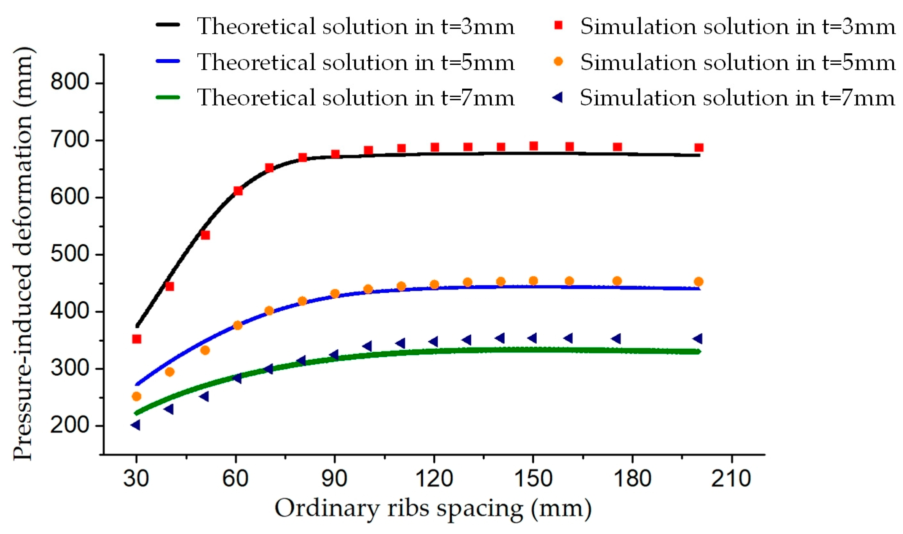
In order to verify the correctness of the optimized mathematical model and optimization results established in this paper, the theoretical method and finite element simulation method are used to calculate the strength and deformation of the pressure hull at a depth of 1000 m, respectively, where the external pressure is 10 MPa and the temperature difference is taken as 25 °C. The stress cloud diagram of finite element simulation analysis is shown in Figure 11. The maximum stress simulation value of the pressure hull is 368.72 MPa, which satisfies the strength constraints in this paper. Figure 12 shows the pressure-induced deformation of the pressure hull at different ordinary ribs spacing l and different thickness of shell plate t . The scatter points are the results of numerical simulation, and the curves are the results of theoretical calculation. The trend of the theoretical and simulation results remained consistent. By means of finite element simulation tests, the correctness of the strength constraint calculation model and the shell compression deformation calculation model established in the previous section is verified.
The comparison of the deformation caused by pressure V P , the deformation caused by temperature V T , and the total deformation V d by the theoretical model and the finite element simulation method are shown in Table 5. The simulation results are obtained by integration of the displacement variation on the mainline in the axial direction. The pressure-induced deformation accounts for more than 75% of the total deformation. The error of the theoretical value of temperature-induced deformation compared with the simulated value is only 2.05%. The error of the theoretical value of pressure-induced deformation compared with the simulated value is also no more than 6%, and these errors are probably caused by the mesh accuracy, force constraints, and simulated stiffness which can be negligible. Then, the correctness of the optimized mathematical model and the optimization results are verified.

6.2. Sea Trials Verification

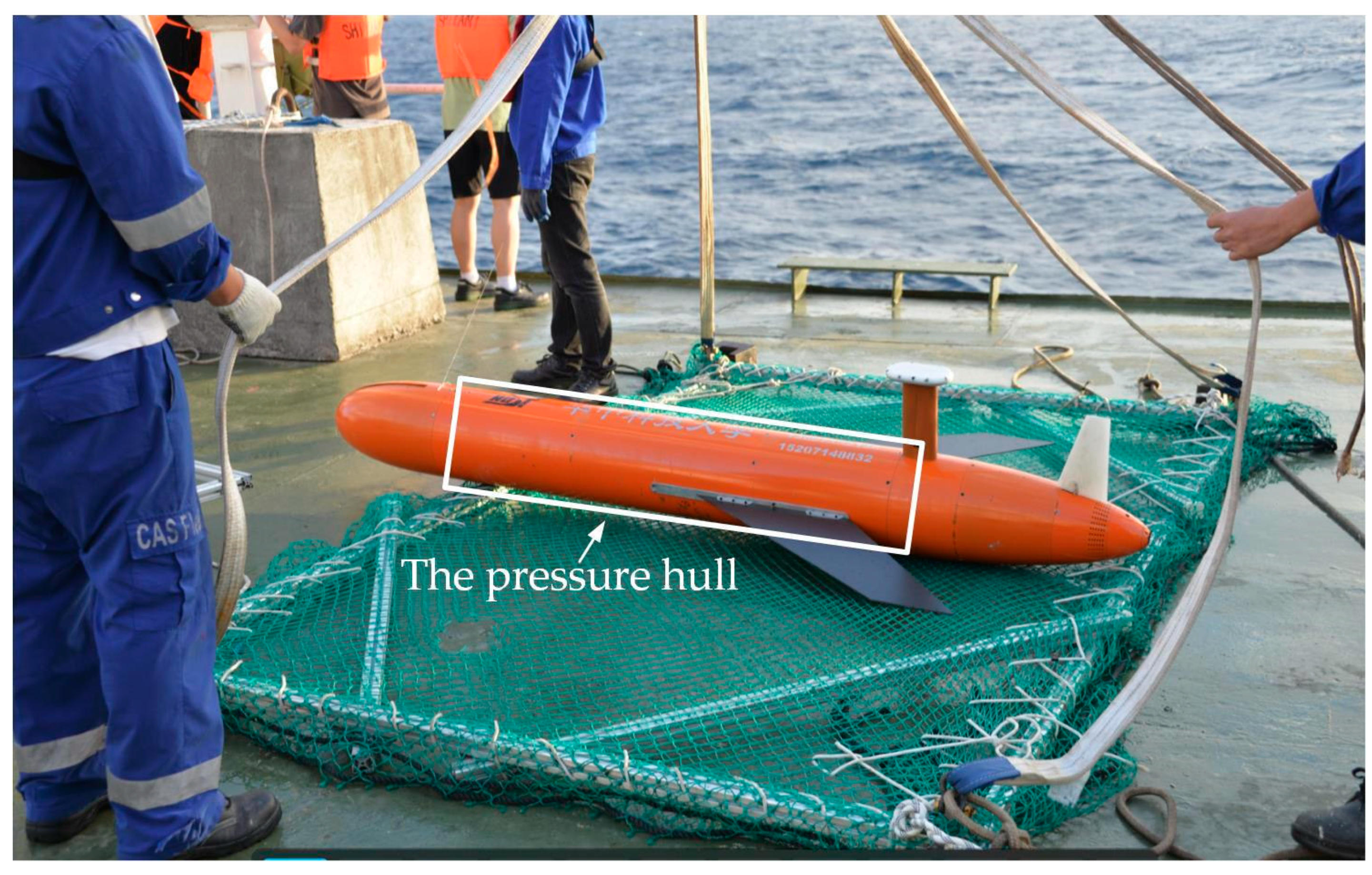
In order to facilitate the installation and assembly of the internal units of the underwater glider, the entire pressure hull was divided into two cabins in the actual manufacturing. As shown in Figure 13, the ribs layout of both cabins is same, and the structural parameters are all consistent with the optimization results in Table 3. Only the oversized rib was changed to split into two cabins of the connecting head for installing seals and screw connections. The connection of the two cabins can be regarded as a special oversized rib structure. The actual weight of optimized pressure hull is 25,147 g, which decreased by 2424 g compared with the original hull. Additionally, the actual energy carried increased by 4.1 MJ.
As shown in Figure 14, the optimized pressure hull is integrated into the underwater glider that is developed by HUST, which the total drainage volume of the underwater glider V 0 is 90.8 L. Additionally, the glider was launched the sea trial in December 2020, in the South China Sea.
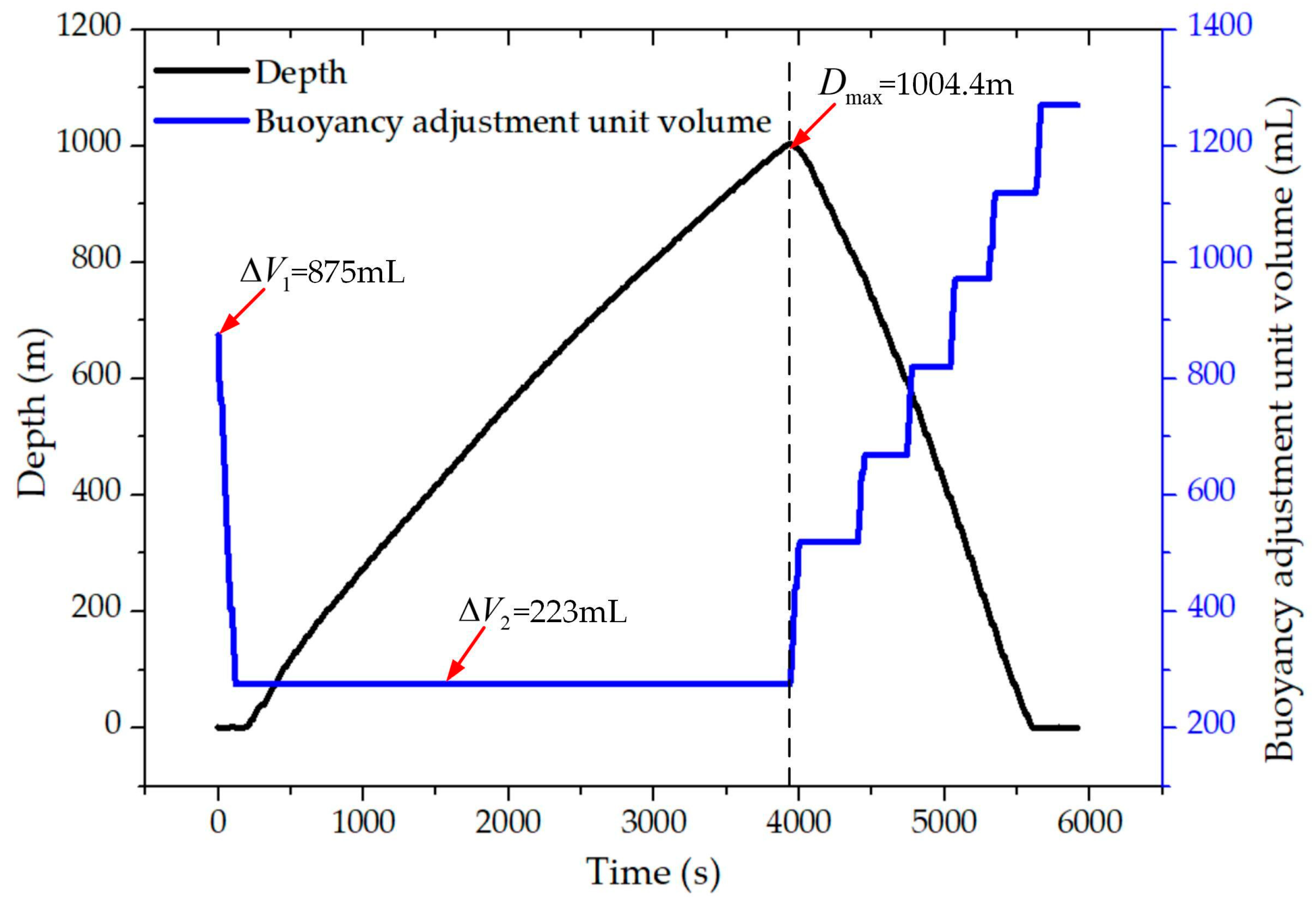
For the test data of a 1000 m depth gliding profile, we will analyze the actual deformation of the optimized pressure hull during gliding process and the effect on the energy consumption of the buoyancy adjustment unit. At the glider starts diving, the density on the sea surface ρ0 is 1020.85 kg/m2. Additionally, at the depth of 1000 m underwater, the density ρ 1000 is 1032.65 kg/m2. The depth and buoyancy adjustment unit volume curves for this profile are shown in Figure 15. The maximum depth of the profile D m a x is 1004.4 m. In the descent preparation phase, the volume value of the buoyancy adjustment unit was adjusted from 875 mL to 223 mL, with a volume change Δ V b of 652 mL. During the descent phase from the surface to the depth of 1000 m underwater, the buoyancy adjustment unit is not working. During the ascent preparation phase and ascent phase, for achieving the speed target, the buoyancy adjustment unit works several times in accordance with the speed change. In the communication preparation phase, the volume value of the buoyancy adjustment unit was adjusted from 875 mL to 1275 mL for better communication quality.
As shown in Figure 16, at the beginning of the descent phase, since the glider is in the thermocline, the density and temperature change drastically, and the glider pitch angle curve and velocity curve show a certain degree of change. After crossing the thermocline, the pitch angle remained stable through the descent phase, with an average value of −39.06°. The gliding speed gradually decreased with the increase in water depth as seawater density increases. During the ascent phase, the gliding angle was stable at about 60°, with an average value of 60.23°. Additionally, the gliding speed increased gradually with the intermittent work of the buoyancy adjustment unit.
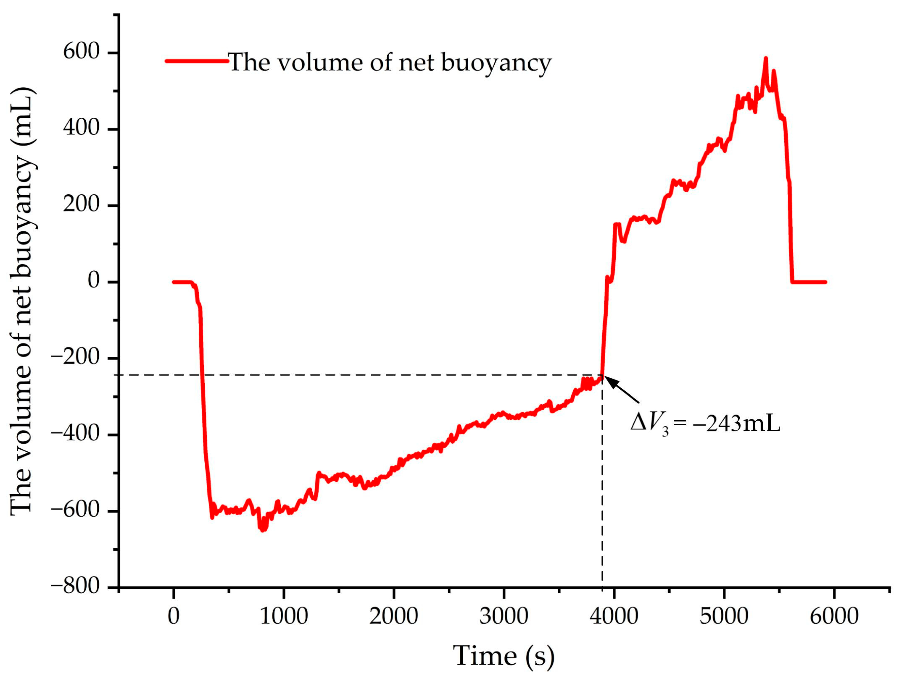
The net buoyancy volume V n of the underwater glider can be calculated from Equations (61) and (62) [27].
V n = 2 B n ρ g = 2 U 2 ( K L 0 + K L α ( γ ) ) ρ g c o s γ
α ( γ ) = K L 2 K D t a n γ ( 1 + 1 4 K D K L 2 c o t γ ( K D 0 c o t γ + K L 0 ) )
where K L 0 and K L are the lift coefficients, K D 0 and K D are the drag coefficients, U is the gliding speed, γ is the gliding angle, and B n is the net buoyancy.
Therefore, the volume of net buoyancy curve of the profile is shown in Figure 17. The trend of this curve is matched with the gliding speed in Figure 16. Additionally, the volume of net buoyancy of this profile at 1000 m depth V n _ 1000 is −243 mL. The volume compression of the pressure hull at the depth of 1000 m underwater V d _ 1000 can be expressed as:
V d _ 1000 = V ρ V b V n _ 1000
Then, the volume deformation of the glider at 1000 m depth V d _ 1000 can be calculated by Equation (63), which has a value of V d _ 1000 is 662 mL. Compared with the data in Table 5, the actual optimized pressure hull is different from the theoretical value by 59 mL with an error of 9.8%, and the difference from the simulation value is 30 mL with an error of 4.7%. The source of this error is analyzed as follows. On the one hand, it may be caused by the volume compression caused by the non-pressure hull part on the underwater glider, including the antenna and buoyancy materials. On the other hand, it may be caused by dividing the pressure hull into two cabins in the actual manufacturing, which leads to the change in the oversized rib structure.
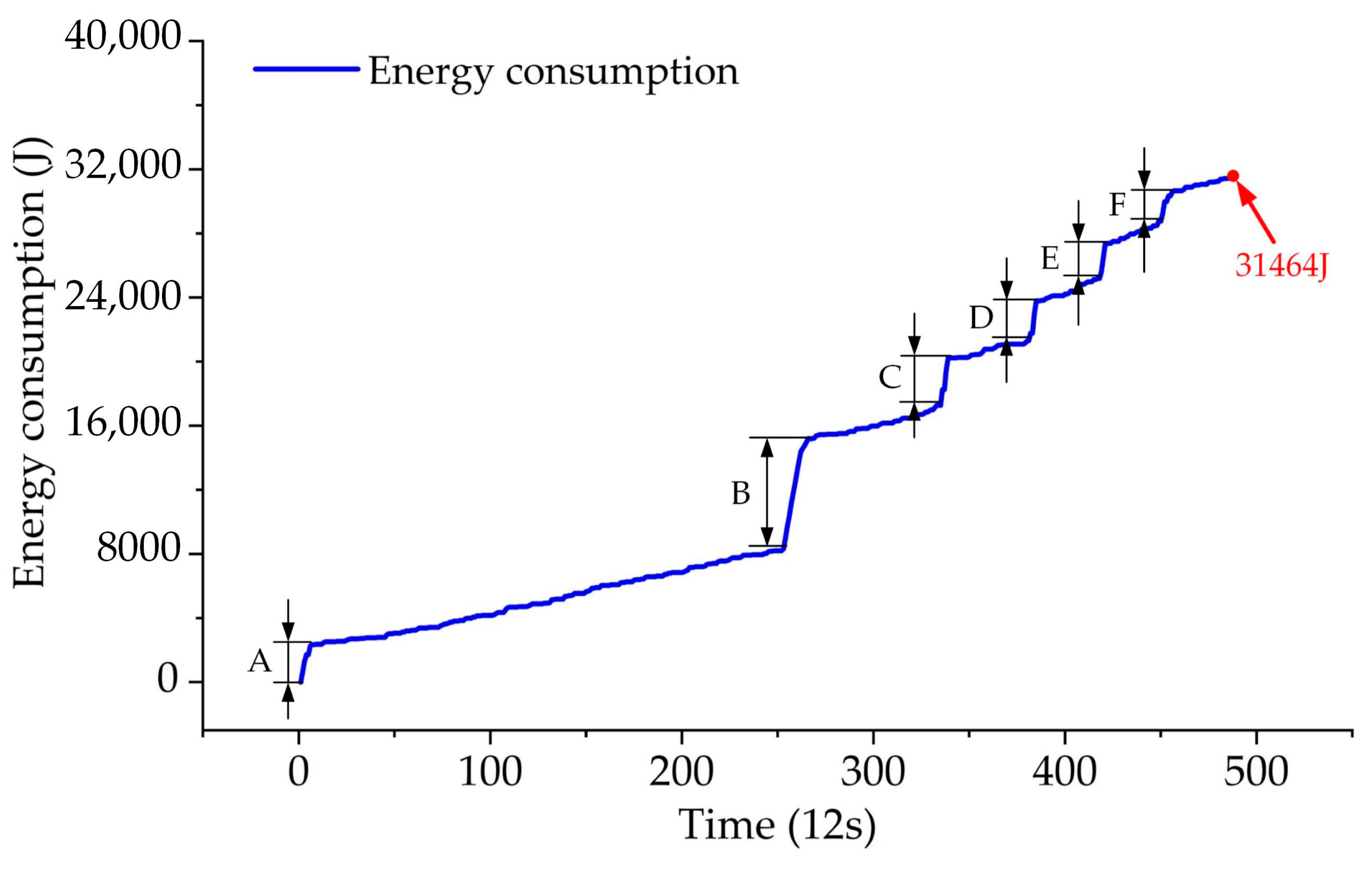
Additionally, the energy consumption curve of the profile is shown in Figure 18. The total energy consumption of this profile is 31,464 J. The energy consumption in the A~F phase increases faster, and it is mainly because the buoyancy adjustment unit is working. For the whole profile, the buoyancy adjustment unit energy consumption accounted for 47.1%.
The actual optimization results of the pressure hull based on energy consumption constraints are shown in Table 6. The weight of the pressure hull m decreased from 27,571 g to 25,147 g, a decrease of 8.8%. The V d _ 1000 increased from 521 mL to 662 mL, an increase of 27.1%. For the time series observation task with the profile depth of 1000 m and the number of profiles, the energy consumption of the buoyancy adjustment unit for a single profile E B decreased from 19,008 J to 14,835 J, a decrease of 21.9%. Additionally, the total energy E 0 increases form 33.12 MJ to 37.22 MJ, an increase of 12.4%. With the total energy consumption of a single 1000 m depth profile (shown in Figure 18), the increased energy of 4.1 MJ can enable the glider to complete an additional 130 observations of 1000 m depth profiles, which will greatly improve the endurance capability of the glider.
In general, by the sea trial tests, it is verified that the optimized pressure hull has a considerable improvement on the energy consumption situation of the underwater glider, and also validated the optimization model and ideas presented in this paper.

7. Conclusions

This paper firstly analyzes the optimization problem of the pressure hull with the working features of underwater glider and relates the optimization problem of the pressure hull with the energy consumption of underwater glider. An optimization model of the pressure hull was built from the perspectives of both increasing energy and reducing energy consumption. For the ring-ribbed cylindrical structure, a theoretical optimization model as well as a strength and stability constraint model for this shell is derived using material mechanics and elasticity mechanics. The HGSAA optimization algorithm was adopted to complete the optimization of the pressure hull. The optimization results show that the underwater glider battery carrying capacity and buoyancy regulation unit energy consumption have been improved considerably. Additionally, using numerical simulation method to verify the accuracy and optimization effect of the mathematical model established in this paper. Finally, the optimized pressure hull was integrated into the underwater glider to carry out the sea trial tests, which further verified the optimization method proposed in this paper and the actual optimization effect of the pressure hull. Specifically, with the optimization of the pressure hull, the total weight reduction in the shell is 2424 g, and the battery carrying capacity is increased by 12.4%. In addition, the volume compression of the pressure hull at 1000 m depth increased by 141 mL, and the energy consumption of the single profile buoyancy adjustment unit was reduced by 21.9%. Finally, the number of observation profiles has increased by 130. The optimization ideas in this paper can be applied to the optimization of the pressure hull for the long-duration underwater vehicles of the same type.
In future work, in order to fully exploit the contribution of the optimized pressure hull to the performance of the underwater glider, corresponding optimization studies can be conducted in terms of the control strategy of the system. Certainly, the new design and optimization of the pressure hull can be performed from the aspects of new structural forms and materials.

Author Contributions

Conceptualization, resources, writing—original draft, J.Z.; supervision, methodology, B.L.; methodology, simulation analysis, Y.P.; sea trial, theoretical analysis, D.Z.; methodology, writing—review and editing, G.Y. All authors have read and agreed to the published version of the manuscript.

Funding

This research is supported by the National Key Research and Development Program of China (No. 2016YFC0301204).

Institutional Review Board Statement

Not applicable.

Informed Consent Statement

Not applicable.

Data Availability Statement

Not applicable.

Acknowledgments

The authors are grateful to the underwater glider research team at HUST. In addition, the authors would like to express appreciation to the staff of the “Shiyan 1” research vessel for their support and assistance in the sea trial tests.

Conflicts of Interest

The authors declare no conflict of interest.

Appendix A

The underwater glider pressure hull is a thin shell, and its study is similar to that of a flat plate. The strain can be represented by six components, including the linear strain in the axial direction ε 1 0 , the linear strain in the circumferential direction ε 2 0 , the shear strain γ 0 , the curvature variation in the axial direction χ 1 , the curvature variation in the circumferential direction χ 2 , and the torsion rate χ 12 .
The linear strain in the axial direction of the middle surface of the pressure cylindrical shell can be expressed as:
ε 1 0 = u x + 1 2 ( w x ) 2
The second term in the above equation is a higher order term relative to the first term, and this paper studies the stability in the case of small deflection, then Equation (A1) can be simplified as:
ε 1 0 = u x
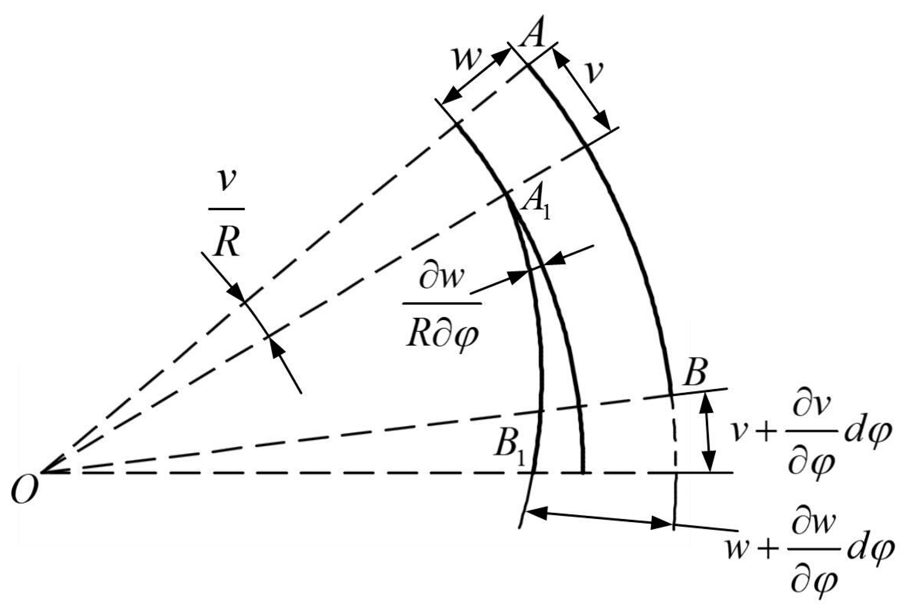
As shown in Figure A1, a section of arc on the middle surface of shell is selected and labeled as A B = R d φ . After its deformation, it is labeled as A 1 B 1 . Define the strain generated by radial displacement as ( ε 0 2 ) w and the strain generated by circumferential displacement as ( ε 0 2 ) v . Since the shell deformation is small, the linear strain in the circumferential direction ε 2 0 can be considered as a linear superposition of the above two variables, as shown in Equation (A3).
ε 2 0 = ( ε 0 2 ) w + ( ε 0 2 ) v = 1 R ( v φ w )
This paper studies the stability in the case of small deflections. Then, the shear strain γ 0 can be expressed as:
γ 0 = R u φ + v x
Additionally, the curvature variation in the axial direction χ 1 can be expressed as:
χ 1 = 2 w x 2
Taking point A as the research point, it can be seen from Figure A1 that the magnitude of angular change θ v generated by circumferential displacement v and satisfies the relation θ v = v / R . The angular change θ w generated by radial displacement w and satisfies the expression θ w = v / R + R w / φ . Then, the curvature variation in the circumferential direction can be expressed as:
χ 2 = 1 R θ A φ = 1 R 2 ( 2 w φ 2 + v φ ) = 1 R 2 ( 2 w φ 2 + w )
Figure A1. Deformation analysis on the circumferential direction.
Jmse 11 00202 g0a1
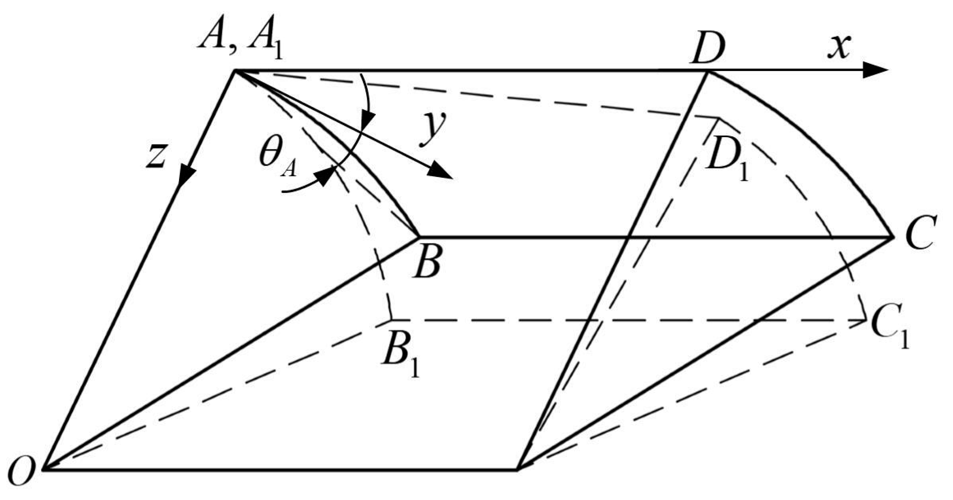
A section of the unit surface in the circumferential direction is taken out of the shell surface, and its variation torsion angle is calculated, which is called the torsion rate χ 12 . As shown in Figure A2, the surface A B C D is deformed to A 1 B 1 C 1 D 1 , and move point A 1 on the deformed surface to coincide with point A . Where the lengths of the arcs A B and C D are R d φ , the lengths of the segments A D and B C are d x , and the expression for the torsion rate can be expressed as:
χ 12 = θ A x = 1 R ( 2 w φ x + v x )
Figure A2. Torsional deformation of the unit body in the shell.
Jmse 11 00202 g0a2
For any point on the shell plate, the strain in the axial direction is shown in Equation (A8).
ε 1 = ε 1 0 z 2 w x 2 = ε 1 0 z χ 1
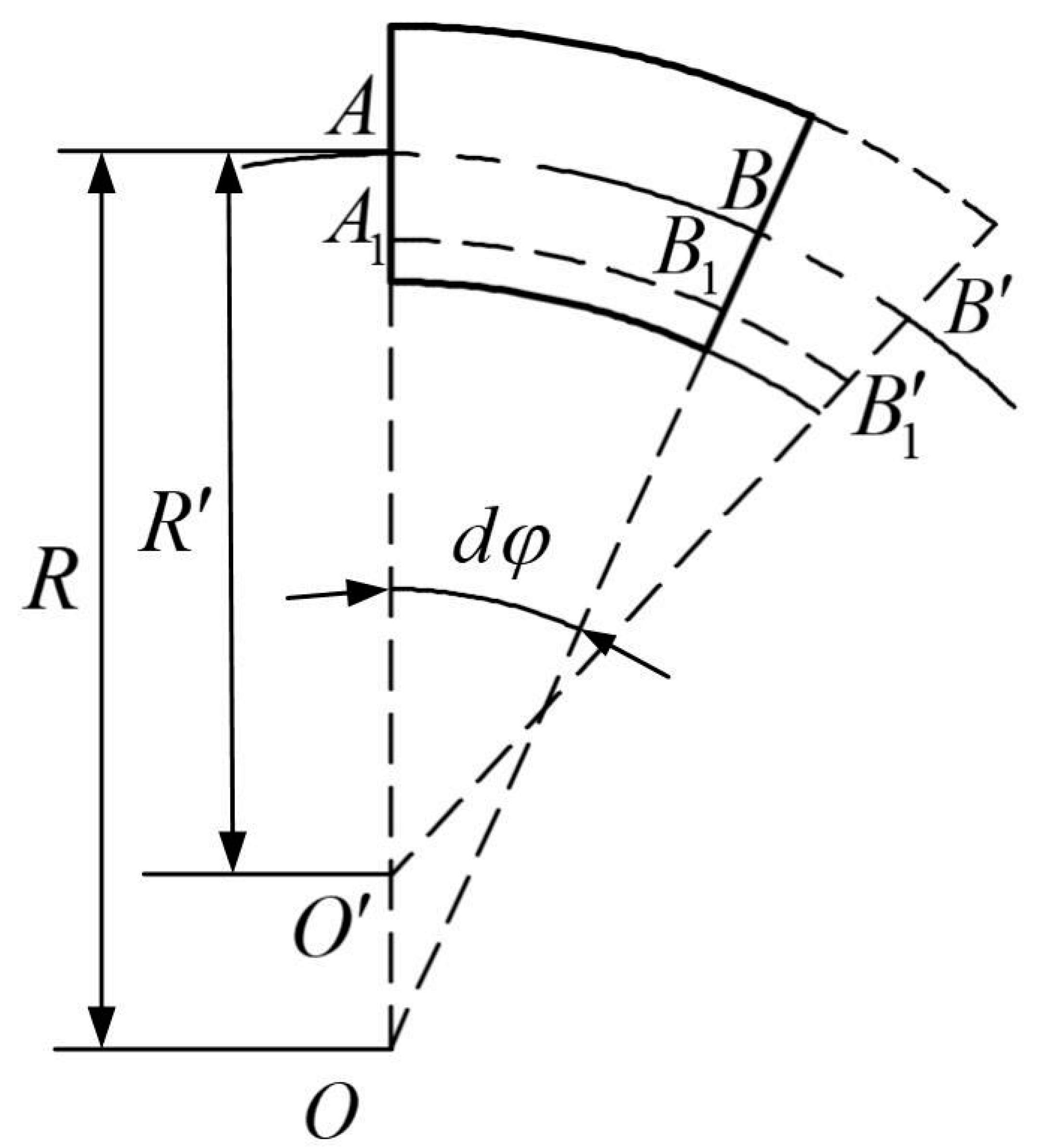
As shown in Figure A3, take any section of the unit arc length on the middle surface of the shell in cross-section, marked as A B , and marked as A B after deformation. Here, moving point A to coincide with point A . The unit arc length at distance z from the middle surface is defined as A 1 B 1 , and marked as A 1 B 1 after deformation. Here, moving point A 1 to coincide with point A 1 . R is the middle surface curvature, and R is the middle surface curvature after deformation. Then, the arc length of each section can be expressed as:
A B = d s ,   A B = d s ( 1 + ε 1 0 ) ,   A 1 B 1 = d s ( 1 z R ) ,   A 1 B 1 = d s ( 1 + ε 1 0 ) ( 1 z R )
Figure A3. Analysis of deformation at any point on the shell.
Jmse 11 00202 g0a3
Thus, the linear strain of the arc length at distance z from the middle surface A 1 B 1 can be expressed as:
ε 2 = A 1 B 1 A 1 B 1 A 1 B 1 = ε 0 2 1 z R z 1 z R [ ( 1 + ε 0 2 ) 1 R 1 R ]
In the above equation, both z / R and ε 0 2 are much less than 1 and can be neglected. So, Equation (A10) can be simplified as:
ε 2 = ε 0 2 z [ 1 R 1 R ] = ε 0 2 z χ 2
As shown in Figure A4, define a slicing unit with length d x , arc length d s , and thickness t . Where the face is A B C D , the parallel surface with distance z from the middle surface is noted as A 1 B 1 C 1 D 1 . The torsion angles around the x and y axes after deformation are marked as ( χ 12 ) 1   ( χ 12 ) 2 , respectively. Then, the shear strain γ is shown as:
γ = γ 0 z [ ( χ 12 ) 1 + ( χ 12 ) 2 ] = γ 0 z χ 12
Figure A4. The shell unit deformation force analysis.
Jmse 11 00202 g0a4

References

  1. Bender, A.; Steinberg, D.M.; Friedman, A.L.; Williams, S.B. Analysis of an autonomous underwater glider. In Proceedings of the Australasian Conference on Robotics and Automation, Canberra, Australia, 3–5 December 2008; pp. 1–10. [Google Scholar]
  2. Rudnick, D.L.; Davis, R.E.; Eriksen, C.C.; Fratantoni, D.M.; Perry, M.J. Underwater gliders for ocean research. Mar. Technol. Soc. J. 2004, 38, 73–84. [Google Scholar] [CrossRef]
  3. Leonard, N.; Paley, D.; Davis, R.; Fratantoni, D.; Lekien, F.; Zhang, F. Coordinated control of an underwater glider fleet in an adaptive ocean sampling field experiment in Monterey Bay. J. Field Robot. 2010, 27, 718–740. [Google Scholar] [CrossRef]
  4. Eriksen, C.C.; Osse, T.J.; Light, R.D.; Wen, T.; Lehman, T.W.; Sabin, P.L.; Ballard, J.W.; Chiodi, A.M. Seaglider: A long-range autonomous underwater vehicle for oceanographic research. IEEE J. Ocean. Eng. 2001, 26, 424–436. [Google Scholar] [CrossRef] [Green Version]
  5. Sherman, J.; Davis, R.E.; Owens, W.B.; Valdes, J. The autonomous underwater glider “Spray”. IEEE J. Ocean. Eng. 2001, 26, 437–446. [Google Scholar] [CrossRef] [Green Version]
  6. Webb, D.C.; Simonetti, P.J.; Jones, C.P. SLOCUM: An underwater glider propelled by environmental energy. IEEE J. Ocean. Eng. 2001, 26, 447–452. [Google Scholar] [CrossRef]
  7. Claustre, H.; Beguery, L.; Pla, P. SeaExplorer glider breaks two world records. Sea Technol. 2014, 55, 19–21. [Google Scholar]
  8. Yang, M.; Wang, Y.; Wang, S.; Yang, S.; Zhang, L. Motion parameter optimization for gliding strategy analysis of underwater gliders. Ocean Eng. 2019, 191, 106502. [Google Scholar] [CrossRef]
  9. Song, Y.; Wang, Y.; Yang, S.; Wang, S.; Yang, M. Sensitivity Analysis and Parameter Optimization of Energy Consumption for Underwater Gliders. Energy 2019, 191, 116506. [Google Scholar] [CrossRef]
  10. Osse, T.J.; Lee, T.J. Composite Pressure Hulls for Autonomous Underwater Vehicles. In Proceedings of the OCEANS 2007, Vancouver, BC, Canada, 29 September–4 October 2007; pp. 1–14. [Google Scholar]
  11. Simitses, G.J.; Aswani, M. Minimum-Weight Design of Stiffened Cylinders Under Hydrostatic Pressure. J. Ship Res. 1977, 21, 217–224. [Google Scholar] [CrossRef]
  12. Mehrabani, M.M.; Jafari, A.A.; Azadi, M. Multidisciplinary optimization of a stiffened shell by genetic algorithm. J. Mech. Sci. Technol. 2012, 26, 517–530. [Google Scholar] [CrossRef]
  13. Akl, W.; Ruzzene, M.; Baz, A. Optimal design of underwater stiffened shells. Struct. Multidiscip. Optim. 2002, 23, 297–310. [Google Scholar] [CrossRef]
  14. Shimoda, M.; Okada, T.; Nagano, T.; Shi, J. Free-form optimization method for buckling of shell structures under out-of-plane and in-plane shape variations. Struct. Multidiscip. Optim. 2016, 54, 275–288. [Google Scholar] [CrossRef]
  15. Liang, C.; Hsu, C.; Tsai, H. Minimum weight design of submersible pressure hull under hydrostatic pressure. Comput. Struct. 1997, 63, 187–201. [Google Scholar] [CrossRef]
  16. Barski, M.; Krużelecki, J. Optimal design of shells against buckling by means of the simulated annealing method. Struct. Multidiscip. Optim. 2005, 29, 61–72. [Google Scholar] [CrossRef]
  17. Hao, P.; Wang, B.; Li, G.; Tian, K.; Du, K.; Wang, X.; Tang, X. Surrogate-based optimization of stiffened shells including load-carrying capacity and imperfection sensitivity. Thin-Walled Struct. 2013, 72, 164–174. [Google Scholar] [CrossRef]
  18. Tang, T.; Li, B.; Fu, X.; Xi, Y.; Yang, G. Bi-directional evolutionary topology optimization for designing a neutrally buoyant underwater glider. Eng. Optimiz. 2018, 50, 1270–1286. [Google Scholar] [CrossRef]
  19. Foryś, P. Optimization of cylindrical shells stiffened by rings under external pressure including their post-buckling behaviour. Thin-Walled Struct. 2015, 95, 231–243. [Google Scholar] [CrossRef]
  20. Yang, M.; Yang, S.; Wang, Y.; Liang, Y.; Wang, S.; Zhang, L. Optimization design of neutrally buoyant hull for underwater gliders. Ocean Eng. 2020, 209, 107512. [Google Scholar] [CrossRef]
  21. Liu, J.; He, B.; Yan, T.; Yu, F.; Shen, Y. Study on carbon fiber composite hull for AUV based on response surface model and experiments. Ocean Eng. 2021, 239, 109850. [Google Scholar] [CrossRef]
  22. Yang, Y.; Liu, Y.; Wang, Y.; Zhang, H.; Zhang, L. Dynamic modeling and motion control strategy for deep-sea hybrid-driven underwater gliders considering hull deformation and seawater density variation. Ocean Eng. 2017, 143, 66–78. [Google Scholar] [CrossRef]
  23. Motygin, O.V.; Nazarov, S.A. Justification of the Kirchhoff hypotheses and error estimation for two-dimensional models of anisotropic and inhomogeneous plates, including laminated plates. IMA J. Appl. Math. 2000, 65, 1–28. [Google Scholar] [CrossRef]
  24. China, C.S. China Classification Society Rules for Classification of Diving Systems and Submersibles; China Communications Press: Beijing, China, 2018; pp. 1–127. [Google Scholar]
  25. Tian, J.; Wang, C.M.; Swaddiwudhipong, S. Elastic buckling analysis of ring-stiffened cylindrical shells under general pressure loading via the Ritz method. Thin-Walled Struct. 1999, 35, 1–24. [Google Scholar] [CrossRef]
  26. Libai, A.; Simmonds, J.G. Nonlinear Elastic Shell Theory. In Advances in Applied Mechanics; Hutchinson, J.W., Wu, T.Y., Eds.; Elsevier: Amsterdam, The Netherlands, 1983; Volume 23, pp. 271–371. [Google Scholar]
  27. Yu, J.; Zhang, F.; Zhang, A.; Jin, W.; Tian, J. Motion Parameter Optimization and Sensor Scheduling for the Sea-Wing Underwater Glider. IEEE J. Ocean. Eng. 2013, 38, 243–254. [Google Scholar] [CrossRef]
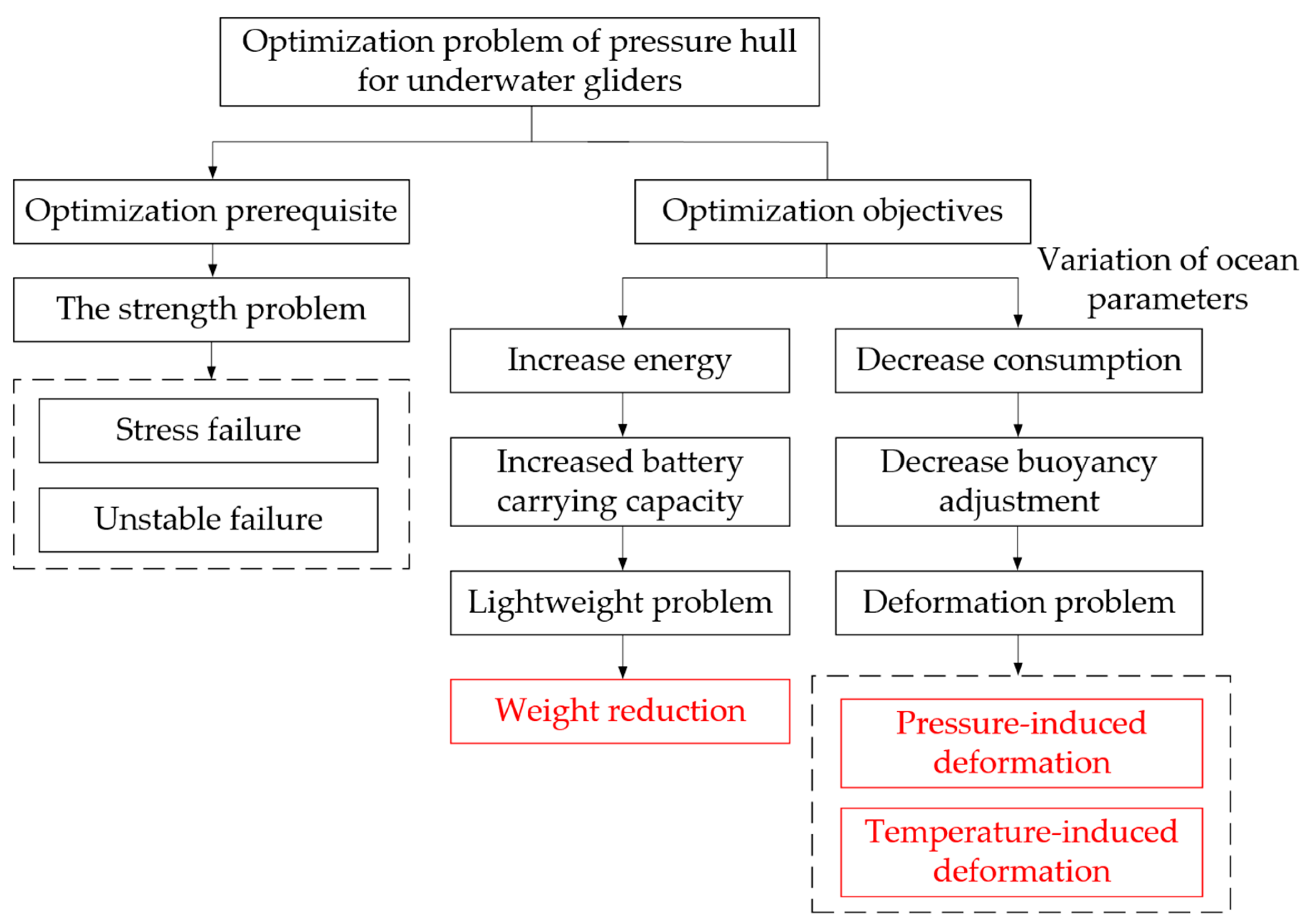
Figure 1. Optimization ideas for the pressure hull.
Jmse 11 00202 g001
Figure 2. Cylindrical coordinates system definition.
Jmse 11 00202 g002
Figure 3. Structural parameters definition of ring rib cylindrical shell.
Jmse 11 00202 g003
Figure 4. Schematic diagram of the slicing unit force.
Jmse 11 00202 g004
Figure 5. The bending deformation of the pressure hull in the direction of mainline.
Jmse 11 00202 g005
Figure 6. The coordinate system for rib stability analysis.
Jmse 11 00202 g006
Figure 7. Analysis of the work performed by external forces on the shell unit.
Jmse 11 00202 g007
Figure 8. Introduction of the various working phases of the glider in the normal gliding mode.
Jmse 11 00202 g008
Figure 9. The flow chart of the HGSAA.
Jmse 11 00202 g009
Figure 10. The fitness evolutionary curves of HGSAA, GA, and SA.
Jmse 11 00202 g010
Figure 11. The finite element simulation analysis of the optimized pressure hull.
Jmse 11 00202 g011
Figure 12. The pressure-induced deformation of pressure hull under different parameters.
Jmse 11 00202 g012
Figure 13. The physical picture of pressure hull.
Jmse 11 00202 g013
Figure 14. The underwater glider integrated optimized pressure hull.
Jmse 11 00202 g014
Figure 15. The depth and buoyancy adjustment unit volume curves of the profile.
Jmse 11 00202 g015
Figure 16. The gliding speed and pitch angle curves of the profile.
Jmse 11 00202 g016
Figure 17. The volume of the net buoyancy curve of the profile.
Jmse 11 00202 g017
Figure 18. The energy consumption curve of the profile.
Jmse 11 00202 g018
Table 1. Energy consumption data of each subsystem of the underwater glider.
Underwater Glider
Subsystems
Average Energy
Consumption (J)
Proportion of Energy Consumption
Buoyancy adjustment unit19,00845.36%
Pitch adjustment unit23765.67%
Rudder unit28446.79%
Control board unit928822.16%
Sensors unit583213.92%
Communication unit25566.1%
Table 2. Material properties of the pressure hull.
ParametersValues
Yield strength σ s 505 MPa
Modulus of elasticity E 72 GPa
Passion’s ratio μ 0.33
Coefficient of thermal expansion α v 2.36 × 10 5 /K
Density ρ 2.81 g/cm3
Table 3. The HGSAA optimization results of structural parameters of the pressure hull.
ParametersOriginal Values
(mm)
HGSAA Results
(mm)
Percentage of Change
t 54.84% decrease
l 12096.619.5% decrease
b 1 2019.24% decrease
h 1 1012.727% increase
b 2 4058.345.75% increase
h 2 2014.826% decrease
Table 4. The HGSAA optimization results of the performance parameters.
ParametersOriginal ValuesHGSAA ResultsPercentage of Change
m 27,571 g24,877 g9.77% decrease
V d _ 1000 521 mL603 mL15.74% increase
E B 19,008 J16,664 J12.33% decrease
E 0 33.12 MJ38.36 MJ15.82% increase
Table 5. Compression of the deformation caused by pressure and temperature.
Volume CompressionTheoretical Results
(mL)
Simulation Results
(mL)
Error
V p 4574835.69%
V T 1461492.05%
V d 6036324.81%
Table 6. The actual optimization results of the performance parameters.
ParametersOriginal ValuesActual Optimized ResultsPercentage of Change
m27,571 g25,147 g8.8% decrease
V d _ 1000 521 mL662 mL27.1% increase
E B 19,008 J14,835 J21.9% decrease
E 0 33.12 MJ37.22 MJ12.4% increase
Disclaimer/Publisher’s Note: The statements, opinions and data contained in all publications are solely those of the individual author(s) and contributor(s) and not of MDPI and/or the editor(s). MDPI and/or the editor(s) disclaim responsibility for any injury to people or property resulting from any ideas, methods, instructions or products referred to in the content.