Article

Numerical Investigation on the Hydrodynamic Response of Pentamaran—Resistance Analysis of Different Outrigger Inclination Angles

1
College of Electromechanical Engineering, Qingdao University of Science and Technology, Qingdao 266061, China
2
Mathematics and Physical Sciences, College of Engineering, University of Exeter, Devon EX4 4QJ, UK
*
Authors to whom correspondence should be addressed.
J. Mar. Sci. Eng. 2023, 11(1), 186; https://doi.org/10.3390/jmse11010186
Submission received: 2 December 2022 / Revised: 3 January 2023 / Accepted: 7 January 2023 / Published: 11 January 2023
(This article belongs to the Section Ocean Engineering)

Abstract

:
Due to the interference between the main hull and the outrigger of the pentamaran, resistance is greatly affected. Therefore, research on the pentamaran front outrigger inclination angle has further practical significance for reducing resistance. In this study, the pentamaran front outrigger inclination angle was analyzed by CFD method, the ship motion in waves was simulated by overlapping grid technology, and the resistance of the pentamaran in static water and waves was predicted by using the unsteady RANS equation. First, a series of validation studies were carried out for the numerical methods used in the study. Then, the influence of the front outrigger inclination angle on the pentamaran resistance performance under different working conditions is calculated and discussed. In order to analyze the influence of the change of the front outrigger inclination angle on the resistance, free surface wave-making and hull pressure are further discussed. The results show that the influence of the front outrigger inclination angle change on the resistance of the pentamaran has a certain rule, and the resistance of the pentamaran can be reduced by adjusting the front outrigger inclination angle.

1. Introduction

The pentamaran has shown great potential in both civil and military areas due to its cost-effective fuel consumption and higher weather capacity compared with the traditional monohull [1]. The pentamaran generally houses a single central slender hull and multi-outriggers, aiming to reduce the residual drag on the hull and increase the ship’s stability. This design can produce a significant lift when the ship cruises at a high speed, which can effectively reduce the wet areas on the hull [2]. Tarafder M S et al. [3] conducted a comprehensive study on the hydrodynamic characteristics of the pentamaran at different speeds. The results showed that when the Froude number Fr > 0.8, the interference between the pentamaran outriggers was very small and the wave-making resistance was significantly reduced. Sulistyawati W et al. [4] conducted a numerical study on the pentamaran outriggers position, and the results showed that the proper outrigger position could reduce the total resistance of the pentamaran by 20.38%. However, the pentamaran may experience large drag resistance when its speed is slow. Moreover, the interactions between the hulls can also influence the hydrodynamic response of the pentamaran. Several previous studies [5,6,7,8,9] concluded that the influence of wave-making interference between hulls can be reduced by properly adjusting the pentamaran outriggers (such as position, shape, etc.), so as to improve the hydrodynamic performance. Vernengo G et al. [10] studied the disturbance effect generated by the inclined outriggers in a small waterline surface catamaran to achieve the best drag performance at medium to high Froude number. The optimal hull shape was also analyzed based on the total drag reduction value and the free surface waveform. The results showed that the total drag value can be reduced by 10% by changing the outrigger structure. The outrigger inclination angle has an important effect on the generated wave disturbance. Deng R, Ni C et al. [11,12,13,14] used the CFD method to study the influence of longitudinal inclination and sinking on drag performance of multihull ships under different conditions. The results showed that the effect of hull attitude on the drag of a multihull ship is not negligible. Shahid M et al. [15] used two turbulence models and three grid sizes for drag prediction of a trimaran, analyzed the effect of the turbulence model and grid structure on the numerical results, and compared the total drag obtained with the experimental results. De Luca F et al. [16] used three hull models of baseline. Experimental data were used to verify the results of the non-constant Reynolds-averaged Navier-Stokes equations for drag coefficients, the wetted area with grid-independent, iterative and time-step convergence analysis. Bulian G, Francescutto A et al. [17] investigated the hull transverse separation distance through regular wave experiments with four different configurations of the trimaran and two configurations of quintuple hull Broglia R et al. [18] conducted an experimental study of the interference effects between the adjacent hulls of a Delft 372 catamaran and detailed the locations where the peaks and troughs of the total drag coefficient curve occur. Wang S M et al. [19] applied the linear wave resistance theory to calculate the wave resistance of a trimaran with a Wigley hull and gave the wave resistance equation for a trimaran in the form of monohull resistance and interference resistance between the main hull and outriggers. Duan W Y et al. [20] applied the 2.5D method to predict the vertical motion (droop and longitudinal rocking) and additional resistance of a trimaran in forwarding waves. In addition, trimaran model tests were conducted to analyze the relationship between the speed, outrigger arrangement, incident wave, vertical swing, longitudinal rocking amplitude and additional drag of the trimaran hull.
In addition, there are several numerical studies of the drag force of multi-hull ships, which can help to advance this study. Nowruzi et al. [21] studied the motion responses of trimaran models under different sea conditions using URANS (Unsteady Reynolds Averaged Navier-Stokes) method. The CFD method is more accurate than the strip theory in predicting the high-speed motion of trimaran because it also takes into account the effects of breaking waves. Gong et al. [22] studied the additional resistance of trimaran ships in inclined waves according to different wave steepness, wave length, wave incidence angle and Froude number. They deduced that ships affected by wave steepness and angle of incidence would increase resistance because the difference in increased resistance between minimum and maximum wave steepness was about 30%. Ghadimi et al. [23] also carried out numerical studies on the motion of trimaran ships in regular and irregular waves. CFD results were verified by experimental and 3D panel method data.
Although there have been many studies on the resistance of multi-hull ships in academic reviews, there are few reports on the influence of the front outrigger inclination angle of the pentamaran on the resistance, but the wave interference between the main hull and the outriggers of the pentamaran is very complex. Therefore, a validated CFD model was used to study the resistance characteristics of pentamaran ships with different front outrigger inclination angles. The resistance changes of pentamaran ships are also analyzed in combination with free surface wave-making and hull pressure. The remainder of this paper is organized as follows: The second section presents the pentamaran model studied in this paper and introduces the numerical model used for the simulation of the pentamaran. The third section verifies the numerical model with CFD through the monohull and the pentamaran. The fourth section introduces the hydrodynamic performance results of the pentamaran with different side angles. The fifth section discusses the main findings based on the CFD results of the pentamaran hydrodynamic characteristics, and the sixth section summarizes the main research conclusions.

2. Numerical Modelling
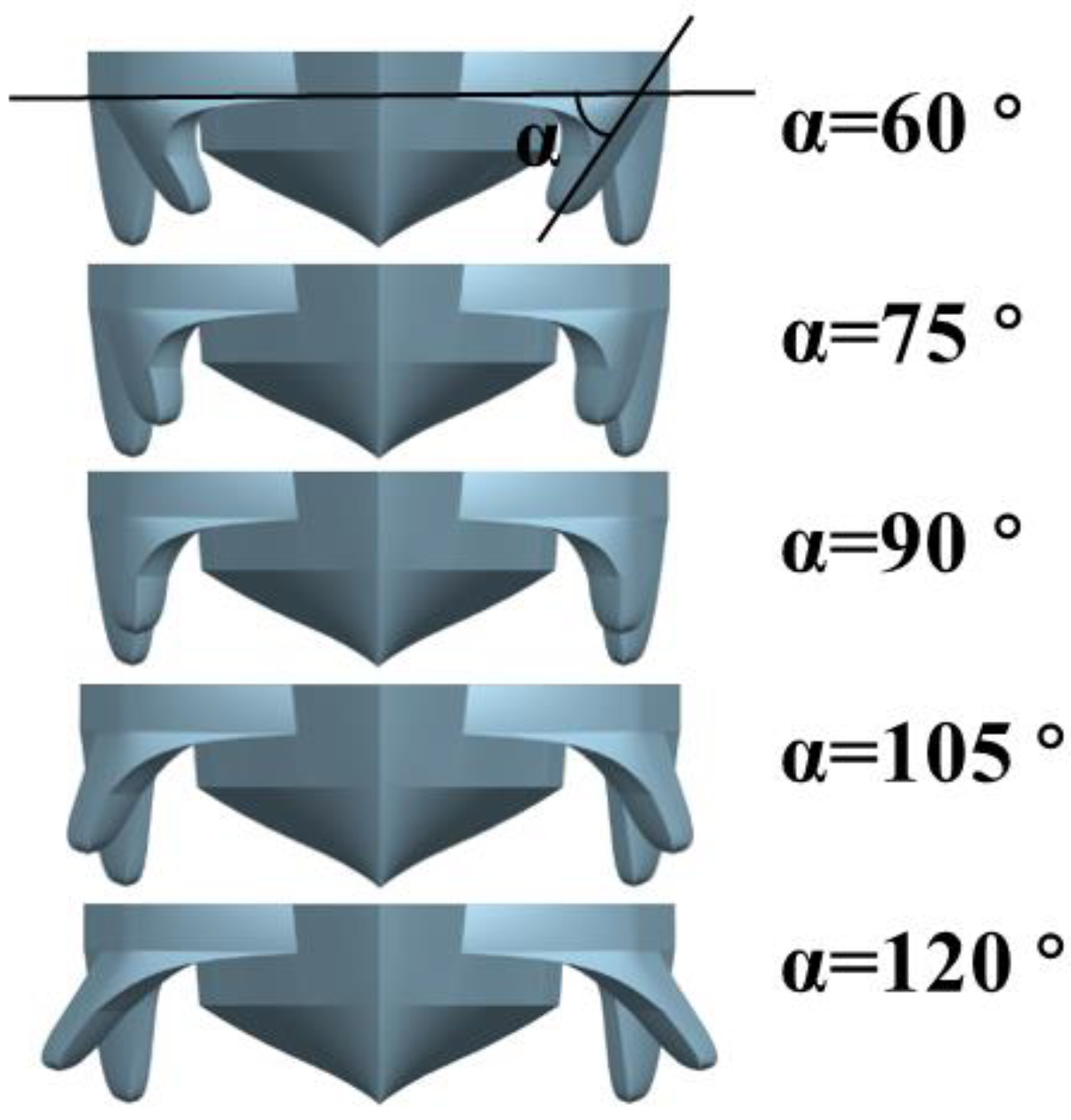
2.1. Pentamaran

An X-shaped symmetrical pentamaran was selected in this study and uses the Wigley hull as the main hull and outriggers. The Wigley hull is thin and long, which conforms to the small disturbance assumption of linear theory [24]. As shown in Figure 1, Table 1, the selected pentamaran consists of the main hull and four outriggers on both sides; two outriggers on each side are located in the same line. The front and rear outriggers are kept at the same distance from the mid-station surface. Considering the same wet surface area and computer performance, a pentamaran model is established every 15 ° in the range of 60 ° to 120 ° front outrigger inclination angle (as shown in Figure 2). Table 1 shows the specific dimensional details of the pentamaran with a total length of 21.464 m.

2.2. Model Configuration

The numerical calculation tool used in this paper is STAR-CCM+, which has been widely used in ship hull design and optimization. This section gives details of the simulation configuration, including the mesh information and boundary conditions.

2.2.1. Simulation Approaching

The vessel motion is a dynamical and nonlinear problem. CFD-based URANS (Unsteady Reynolds Averaged Navier-Stokes) are essential to simulate the vessel motion phenomenon by means of a fully nonlinear method [25]. The URANS solution is time accurate, as it is based on the Implicit Unsteady approach. In the Implicit Unsteady method, each physical time step involves some number of inner iterations to converge the solution for that given instant of time [26,27]. The governing equation of this fluid mechanics study consists of the continuity equation and momentum conservation equation. The governing equations is defined as:
u i / x i = 0
t ( ρ u i ) + x i ( ρ u i u j ) = P x i + x j [ μ ( u i x j + u j x i 2 3 δ i j u l x l ) ] + x j ( ρ u i u j ¯ ) + m i
where: i and   j are the components of variables in the i th and j th directions, respectively, in the coordinate system; P is the pressure;   u is the velocity vector; ρ is the fluid density;   m is the mass force.
To calculate the turbulent flow, additional turbulence equations are also required. The K-Epsilon [28,29] turbulence model was selected because it can solve the transport equations for turbulent kinetic energy and turbulent dissipation rate to determine the turbulent vortex viscosity. This turbulence model is applicable when there is no high pressure change along the hull, and is quite economical in terms of CPU time [30]. Compared with the SST turbulence model, for example, the SST turbulence model increases the required CPU time by almost 25% [31]. The transport equations of turbulent kinetic k energy and turbulent dissipation rate ε are as follows:
t ( ρ k ) + x i ( ρ k u i ) = x j [ ( μ + μ t σ k ) k x j ] + G k + G b ρ ε Y M + S k
t ( ρ ε ) + x i ( ρ ε u i ) = x j [ ( μ + μ t σ ε ) ε x j ] + C 1 ε ε k ( G k + C 3 ε G b ) C 2 ε ρ ε 2 k + S ε
where: G k represents turbulent kinetic energy generated by laminar velocity gradient, G b represents turbulent kinetic energy generated by buoyancy, and Y M represents wave motion generated by diffusion in compressible turbulence, C 1 ε , C 2 ε ,   C 3 ε is a constant, k   and   ε are turbulent Prandtl numbers of k equation and ε equation, S k and S ε are user-defined numbers.
The volume of fluid domain (VOF) method was used to solve the free surface problems. The VOF model can not only generate regular waves with different wave lengths and heights by defining boundary conditions, but also control the velocity and pressure parameters of the inlet and the influence of the hull attitude on the total drag; it is not negligible during the simulation [32]. The Dynamic fluid body interaction (DFBI) module was used to obtain the hull position and sailing attitudes in this research. The DFBI module includes solving force and moment on hull surface, and 6 DOF rigid body motion model. Two different coordinate systems are defined as shown in Figure 1: The Earth coordinate system OX0Y0Z0 and the ship coordinate system GXYZ with the ship’s center of gravity G as the origin, and the flow direction in the x-negative direction. To simulate waves and damping, and to improve the simulation accuracy, fifth-order VOF waves were created in the model, which was modeled using the fifth-order approximation of Stokes wave theory and is closer to the true wave than the wave generated by the first-order method [33]. A two-layer full-y+ wall treatment was used in the simulation, aiming to obtain a better corresponding to the K-Epsilon two-layer model [33]. The two-layer full-y+ wall treatment used for the boundary layer treatment is a hybrid model. For the coarse grid, it has y+ >30 and for the vicinity of the hull surface, y+ ≈ 1. This model can accurately predict the turbulence parameters of the entire wall boundary layer when dealing with most fluid problems of practical significance.

2.2.2. Computational Domain and Mesh Generation

Numerical simulations with different front outrigger inclination angles were selected to predict the drag characteristics of a pentamaran under hydrostatic and regular head waves in the range of Froude number (0.2–0.8). The computational domain and boundary condition settings of CFD simulations are vital for result accuracy. As shown in Figure 3, the ITTC recommendations were considered for the creation of the computational domain: five times the length of the ship and 1.5 times the length of the pentamaran from both sides of the boundary. The same size computational domain was used in all cases. Considering the symmetry of the pentamaran with respect to the centerline plane, half of the model was taken for the simulations to reduce the computational cost. The boundary conditions on both sides are set as symmetric planes, which do not allow the velocity and pressure to change through it, approaching an infinitely wide deep sea, and do not allow the Kelvin wake to reach the boundary in any case. The boundary conditions were set as shown in Figure 3 (the inlet, top, and bottom boundary conditions of the region were selected and set as velocity inlet, the boundary conditions of the outlet were set as pressure outlet, and the boundary conditions of the side, as well as the symmetry plane, were set as symmetry plane). To eliminate the wave reflection generated at the outlet boundary, VOF wave damping was added at the pressure outlet.
Grid generation used trimmed hexahedral types throughout the watershed [34,35], which are refined for hull parts with large curvature changes such as overlapping areas, free surfaces, bows and aft. In Begovic et al. [36], two hybrid meshes (polyhedral and trimmed) and two trimmed meshes were used to perform a detailed mesh types sensitivity analysis of the damaged ship movement. The simulation results indicate that the hybrid meshes are prohibitive due to high time consumption and poor simulation accuracy, while the trimmed meshes are recommended. When the ship is moving in still water or waves, the Overset grid around the hull will be deformed along with the ship’s motion. As shown in Figure 3, Figure 4 the cut-body grid cells were used with anisotropic grid refinement in the direction normal to the free liquid surface. This consideration can refine the sharp corners of the hull and improve the mesh resolution. Figure 4 shows the mesh refinement around the hull and hull. According to the numerical study by Dogrul A et al. [37], the prismatic layer mesh around the hull surface as near-wall refinement can increase the near-wall mesh density and decreases the numerical spread near the wall surface.

2.2.3. Sensitive Study of Mesh Numbers and Time Step

A sensitive study on the mesh numbers and time was conducted for the CFD model with the case of outrigger inclination angle α = 90 ° at a velocity of Fr = 0.3. In order to verify the convergence of the grid, six grids of different sizes were used. The size Convergence Study of A, B and C grids is based on 0.04 s of time step and that of D, E and F is based on 0.02 s of time step. Table 2 shows the number of specific grids and nodes as well as the simulation results. When the number of grids exceeds 3 million a more stable resistance value can be obtained, and the effect of further increasing the number is not significant; the total resistance value is stable at about 11290 N. Therefore, grid C has reached convergence. In the following research, grid C will be used for numerical research. Five time steps were selected for the time step convergence study (as shown in Table 3). The verification results show that when the time step is less than 0.04s, the simulated total resistance converges near 11290 N, which meets the requirement of convergence accuracy. Considering the computer performance and calculation time, we use 0.04 s time step for numerical study.

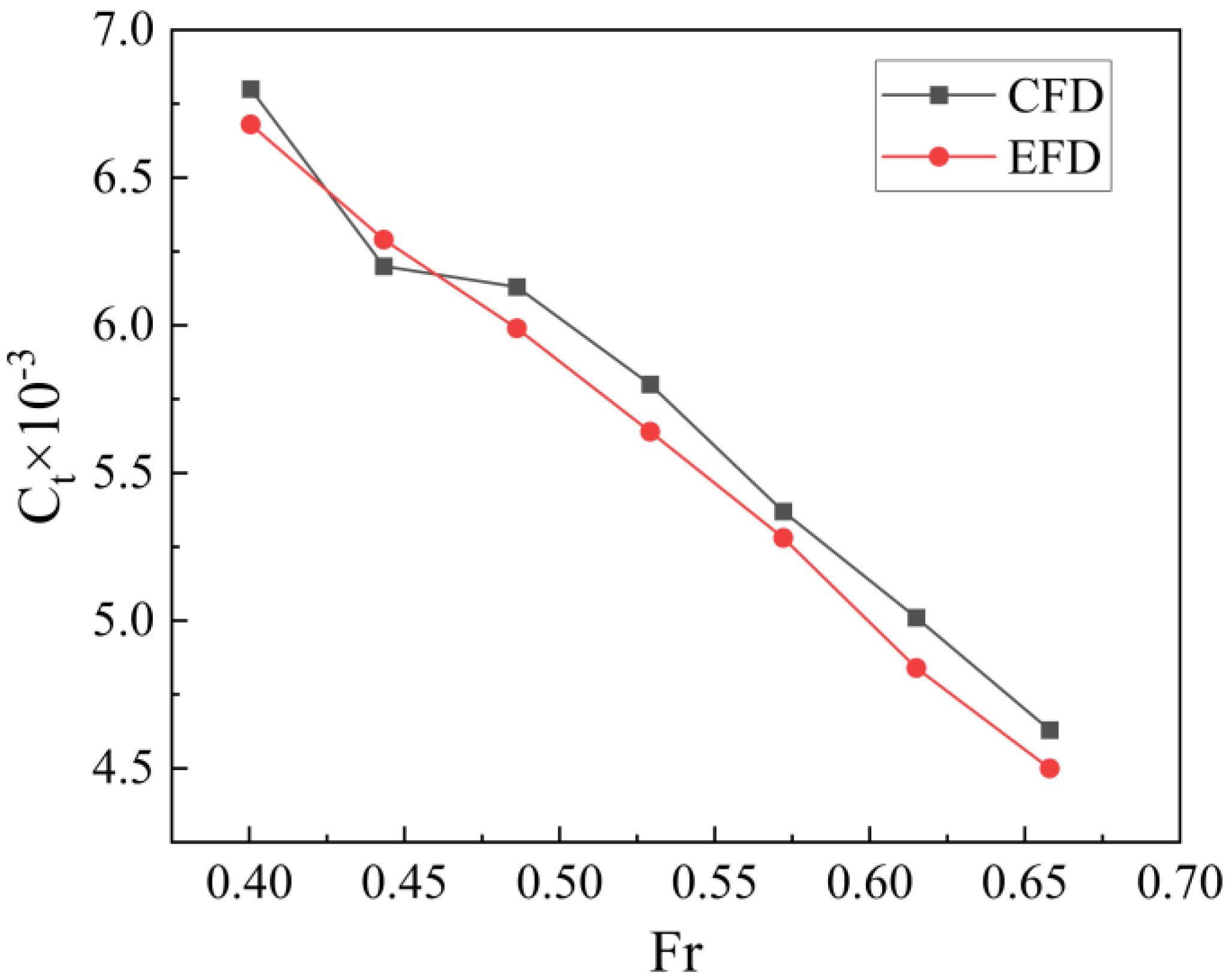
2.3. Model Validation

Considering the basin test of the pentamaran is incomplete, this model selected another ship, named KCS, to validate the above numerical approaching. Kim et al. [38] carried out towing pool tests on KCS ships and published resistance data. The KCS ship model is shown in Figure 5 and the main details of the KCS ship are shown in Table 4, with the Froude scaling ratio λ = 31.6. In the numerical model, the entrance velocity is specified at the upstream entrance boundary to simulate the towing speed. The heaving and pitching of the ship are considered in the simulation, calculated using the Froude number Fr = 0.2599.
Resistance coefficient calculation formula
C t = R t ρ 2   v 2 A
Here   C t is the drag coefficient, R t   is the total drag, v is the ship speed, and A is the scaled area of the hull and rudder. In order to reduce the computing time, the simulation was performed only for half of the ship model. Consequently, the drag coefficient was multiplied by 2. Shown by Table 5, the differences between the STAR-CCM+ model and other models are not significant (less than 1%). It can be seen from Figure 6 that the free surface waveforms obtained from the STAR-CCM+ simulations are closer to those obtained in the hydrostatic tests of Kim et al.
To further verify the accuracy of the numerical simulation of the resistance of the pentamaran by STAR-CCM+, we performed numerical simulations of hydrostatic resistance using the warp-chine pentamaran studied by Sulistyawati [10] with a length of 1.436 m and four identical outriggers of length 0.414 m distributed in an X-shape. The obtained numerical results were compared with the model test results of Sulistyawati et al. From the comparison results (Figure 7), it can be seen that the errors of CFD and EFD of warp-chine pentamaran at multiple speeds are small (about 4%). It should be pointed out that during the numerical validation of the above two types of ships, only the grid used has been enlarged or reduced equally in size. The numerical models used in this paper are validated by two different ship models of different sizes and types. The results show that the grid and physical models used in this paper have good migration characteristics, and reliable results can also be obtained when solving the pentamaran resistance problem studied in this paper.

3. Numerical Results and Discussion

This section reports the results of the pentamaran response in static water and waves.

3.1. Hydrostatic Results

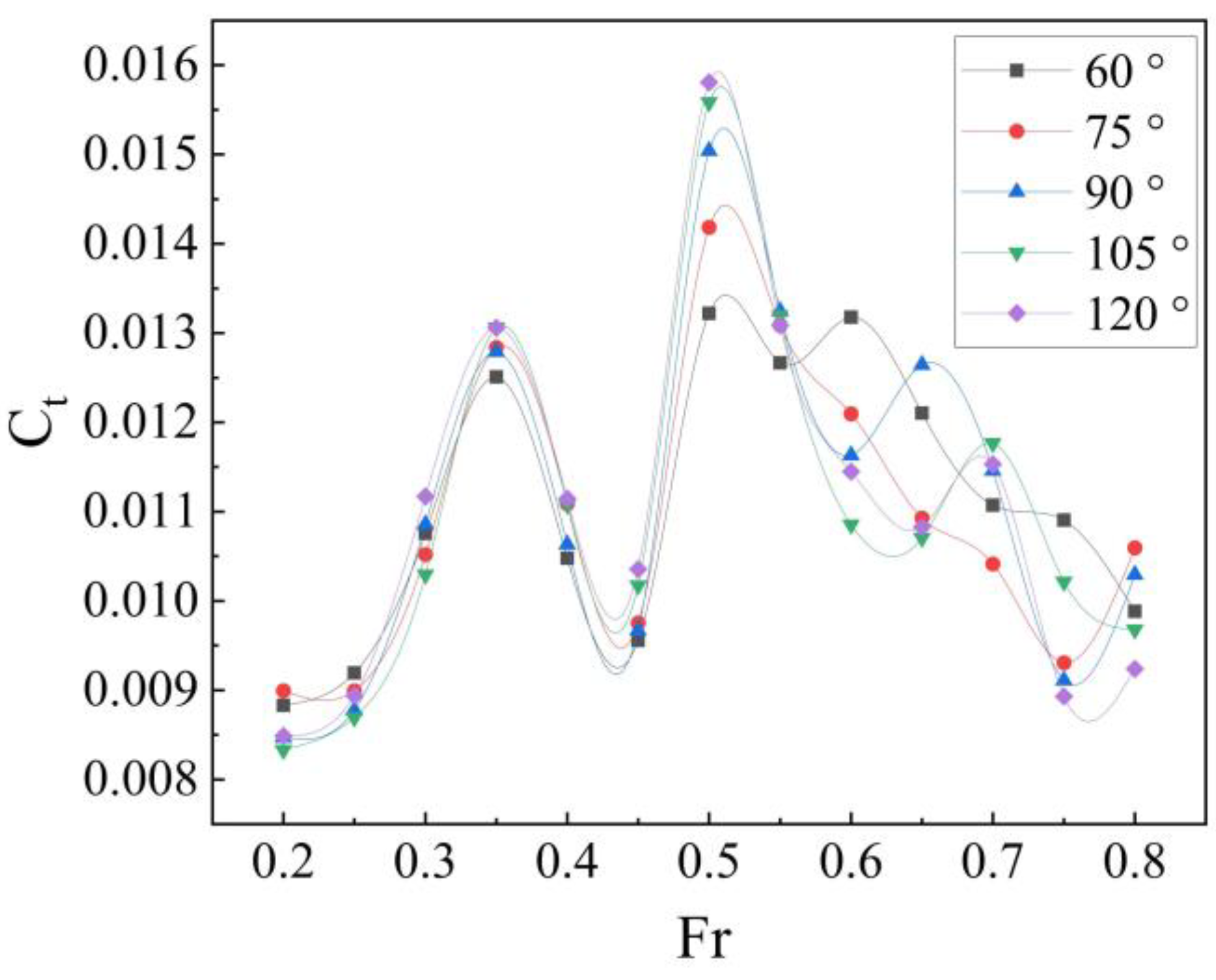
3.1.1. Total drag Coefficient under Static Water

Figure 8 shows the total drag coefficients of front outriggers with 5 different inclinations when Fr0.2–0.8. The variation of the total drag coefficients was analyzed to derive the outrigger inclination angles adapted to different speeds. Table 6 shows the shipping speed of the pentamaran corresponding to different Froude numbers.
Shown by Figure 8, the effects caused by the change of outrigger inclination are less significant with smaller Froude numbers. The C t value of 105 ° configurations is low relative to the other four configurations when Fr ≤ 0.3. The C t value of 60 ° configurations then becomes the smallest one in the interval of 0.3 < Fr ≤ 0.55; the inclination effect is the most significant under a Fr = 0.5 case, near the velocity Fr = 0.5, there will be a peak C w of the wave-making resistance coefficient, the similar results were obtained by Yuanr et al. [8]. Therefore, for low speed pentamaran with 0.2 < Fr ≤ 0.3, increasing the outriggers inclination will reduce the resistance. For pentamaran with speeds of 0.3 < Fr ≤ 0.55, reducing the outriggers inclination will reduce the resistance. When the Fr > 0.55, there is no single angle configuration that can maintain the lowest C t value consistently in the studied Froude number range.

3.1.2. Free Surface Wave Generation and Hull Pressure Analysis

The speed Fr = 0.5 was chosen for the analysis of free-surface wave-making and hull pressure. At this speed, the total drag coefficient of the pentamaran is the largest. Figure 9 compares the waves near the front outrigger of the five models when Fr = 0.5. The influence of the front outrigger inclination angles on the ship wave-making is mainly reflected in the head of the front outrigger. As can be clearly seen in Figure 9, the pentamaran with 60 ° front outrigger inclination has the lowest wave-making height at the head of the front outrigger. With the increase of the front outrigger inclination angles, the wave-making height at the head of the front outrigger has an obvious upward trend, which is also the reason for the increase of the total resistance. When Fr = 0.5, compared with the wave-making of the pentamaran with 90 ° front outrigger inclination, with the decrease of the front outrigger inclination angle (e.g., 60 °and 75 °) the front outrigger can better avoid the bow-rising waves, which will significantly reduce the resistance of the ship when sailing. With the increase of the front outrigger inclination angle (e.g., 105 °and 120 °), greater waves are formed when the wave from the front outrigger is coupled with the wave from the bow of the pentamaran, which increases the resistance of the ship.
Figure 10 compares the hull surface pressure coefficients of the five models when Fr = 0.5. It can be seen that with the increase of the front outrigger inclination angle, a larger area of high pressure occurs at the connection between the outrigger and the main body. This change in pressure is due to wave coupling, and results in a greater pressure difference between the bow and the stern, which increases the resistance of the pentamaran.
When Fr = 0.5, reducing the front outrigger inclination angle can reduce the wave energy loss in the flow field and optimize the wave height generated by the pentamaran. The phenomena in Figure 9 and Figure 10 explain why the total drag coefficient decreases with the decrease of the outrigger inclination angle when Fr = 0.5. The analysis of this phenomenon is also helpful to understand the effect of the changes in the outrigger inclination angle on the performance of the pentamaran.

3.2. Resistance of a Pentamaran in Waves

In this section, the pentamaran drag force analysis was performed in the case of regular waves with 1m wave amplitude and wave lengths λ of 1, 1.25 and 1.5 times the length of the ship at three speeds. Figure 11 shows the total drag coefficient of the pentamaran at three speeds. As can be seen in Figure 11, when Fr = 0.3, the total drag coefficient of the pentamaran with a 60 ° front outrigger inclination is the lowest under three different wave lengths. When Fr = 0.5 and Fr = 0.7, the 105 ° configuration has better resistance performance than other configurations under three conditions, which also shows that changes in the front outrigger inclination can improve the wave disturbance to reduce resistance. The average resistance of the pentamaran in regular waves is shown in Table 7. When Fr = 0.3, the maximum resistance reduction of the pentamaran with α = 60 ° configuration is 7.2% compared with the pentamaran with α = 90 ° configuration. When Fr = 0.5 and 0.7, the maximum drag reduction of the pentamaran with α = 105 ° is 3.8% compared with the pentamaran with α = 90 °. Figure 12 shows the total resistance time history of the pentamaran when λ/L = 1.25. The transverse axis represents the time, and the longitudinal axis represents the total resistance value. From Figure 12, it can be seen that the wave motion causes periodic changes in the resistance of the pentamaran, but the peak resistance values of the pentamaran with α = 60 ° and α = 120 ° configurations are significantly higher than those in other configurations, which also indicates that the pentamaran in these two configurations will generate large instantaneous resistance values.

3.3. Discussion

In this paper, a numerical simulation method was used to conduct a hydrodynamic study of an X-shaped symmetrical pentamaran, and the study focuses on the effect of the front outrigger inclination angle change on the pentamaran drag characteristics, which is in the range of 0.2–0.8 Froude number. Firstly, five models of the forward outrigger inclination were designed with outrigger inclination from 60 ° to 120 °. Secondly, the validation study was carried out based on the monohull and quintuple hull, and by comparing the CFD and EFD results; the errors of the monohull and the quintuple hull are less than 0.78% and 4%, respectively, and the convergence study was carried out on the grid and time step. The validation study was performed at a Froude number of 0.3, which is considered a critical point because after this Froude number, the pressure-based drag component increases sharply with increasing speed.
In the hydrostatic numerical simulation of the pentamaran, it was found that under different Fr, the influence of the front outrigger inclination angle change on the resistance of the pentamaran is different. However, when Fr = 0.5, the resistance of the pentamaran decreases significantly with the decrease of the front outrigger inclination angle. Through analysis of Figure 9 and Figure 10, it can be concluded that front outrigger inclination angle changes affect the wave-making height, resulting in significant changes in the pressure at the front outrigger connection, which is also the reason for the increase or decrease of resistance.
In the numerical simulation study of regular wave of the pentamaran, it was found that when Fr = 0.3, the drag reduction of pentamaran with α = 60 ° is remarkable under all conditions. Compared pentamaran with α = 90 °, the drag reduction is about 3.2% when λ/L = 1, 2.4% when λ/L = 1.25 and 7.2% when λ/L = 1.25. However, when Fr = 0.5 and 0.7, the resistance of pentamaran with α=105 ° is significantly reduced under the conditions of this study, with a maximum reduction of 3.8% compared with the pentamaran with α = 90 °. From the analysis of Figure 12, it can be concluded that the pentamaran with α = 60 ° and α = 120 ° configuration has large instantaneous resistance, which may affect the structural strength of the pentamaran to some extent. Therefore, when designing a pentamaran with seaworthy speed, it is possible for the pentamaran have optimal drag by changing the outrigger inclination angle. When multiple operating speeds are required, it is also possible to design a pentamaran with variable outrigger inclination.

4. Conclusions

In this paper, the influence of front outrigger inclination angle on total drag and total drag coefficient for five hulls in static water and regular wave conditions was investigated. The main conclusions that can be drawn are: (1) The front outrigger inclination change will change the pentamaran wave-making height. (2) When the speed range of the pentamaran with 120 ° front outrigger inclination is 0.2 < Fr ≤ 0.3, or when the speed range of the pentamaran with 60 ° front outrigger inclination is 0.3 < Fr ≤ 0.55, the front outrigger can avoid the bow wave crest and the resistance coefficient is significantly reduced. (3) At low speeds, the reduction of front outrigger inclination will significantly reduce the total resistance. At medium and high speed, the increase of front outrigger inclination can reduce the resistance, but when it exceeds 105 °, the resistance will increase. (4) For pentamaran in regular wave research, when Fr = 0.3, the pentamaran with α = 60 ° has the lowest total resistance, and when Fr = 0.5 and 0.7, the pentamaran with α = 105 ° has the lowest resistance.
The author demonstrates that a change of the forward outrigger inclination of a pentamaran can reduce the ship’s drag. The results may be of some reference value to researchers designing new pentamaran or ship type optimizations. However, there are also some shortcomings in the study. For example, because the force of the pentamaran is very complex, the force of different parts has not been studied in this paper. Since there is little research on the pentamaran, there is no comparative analysis with the same type of ship in this paper. In future research, the towing pool test will be carried out on the pentamaran model, and the force of different parts of the pentamaran will be considered separately as well as considering more operating conditions, including wind, wave and speed. This gradual improvement of the pentamaran will also present a greater challenge to the current approach.

Author Contributions

Conceptualization, Y.C. and P.H.; methodology, P.H.; software, P.H.; validation, P.H. and C.Z.; formal analysis, Y.L.; investigation, B.L.; resources, Y.C.; data curation, P.H.; writing—original draft preparation, P.H.; writing—review and editing, C.Z. and P.H.; visualization, P.H.; supervision, C.Z.; project administration, Y.C.; funding acquisition, Y.C. All authors have read and agreed to the published version of the manuscript.

Funding

The research is financially supported by the National Natural Science Foundation of China (Grant No. 51909127), the Key R & D Project of Shandong Province (Grant No.: 2018YFJH0704 and 2019GHZ007), and the Doctoral Scientific Research Starting Foundation of Qingdao University of Science and Technology.

Institutional Review Board Statement

Not applicable.

Informed Consent Statement

Not applicable.

Data Availability Statement

Not applicable.

Conflicts of Interest

The authors declare no conflict of interest.

References

  1. Zaghi, S.; Broglia, R.; Di Mascio, A. Analysis of the interference effects for high-speed catamarans by model tests and numerical simulations. Ocean Eng. 2011, 38, 2110–2122. [Google Scholar] [CrossRef]
  2. Sulistyawati, W.; Pamitran, A.S. Michell’s thin ship theory in optimization of warp-chine on pentamaran configuration. J. Appl. Fluid Mech. 2019, 13, 909–921. [Google Scholar]
  3. Tarafder, M.S.; Ali, M.T.; Nizam, M.S. Numerical prediction of wave-making resistance of pentamaran in unbounded water using a surface panel method. J. Procedia Eng. 2013, 56, 287–296. [Google Scholar] [CrossRef] [Green Version]
  4. Sulistyawati, W. CFD investigation of pentamaran ship model with chine hull form on the resistance characteristics. IOP Conf. Ser. Mater. Sci. Eng. 2018, 316, 012059. [Google Scholar]
  5. Sulistyawati, W.; Pamitran, A.S. Warp-chine on pentamaran hydrodynamics considering to reduction in ship power energy. Energy Procedia 2019, 156, 463–468. [Google Scholar] [CrossRef]
  6. Wang, C.-N.; Yang, F.-C.; Nguyen, V.T.T.; Vo, N.T.M. CFD Analysis and Optimum Design for a Centrifugal Pump Using an Effectively Artificial Intelligent Algorithm. Micromachines 2022, 13, 1208. [Google Scholar] [CrossRef]
  7. Waskito, K.T.; Karim, S.; Ichsan, M. Interference resistance of pentamaran ship model with asymmetric outrigger configura-tions. J. Mar. Sci. Appl. 2017, 16, 42–47. [Google Scholar]
  8. Wiwin, S. Pentamaran configuration design with modeling hull form for resistance minimization. In IOP Conference Series: Earth and Environmental Science; IOP Publishing: Bristol, UK, 2018; Volume 105, p. 012043. [Google Scholar]
  9. Nguyen, T.V.T.; Huynh, N.-T.; Vu, N.-C.; Kieu, V.N.D.; Huang, S.-C. Optimizing compliant gripper mechanism design by employing an effective bi-algorithm: Fuzzy logic and ANFIS. Microsyst. Technol. 2021, 27, 3389–3412. [Google Scholar] [CrossRef]
  10. Vernengo, G.; Brizzolara, S. Numerical investigation on the hydrodynamic performance of fast SWATHs with optimum canted struts arrangements. Appl. Ocean Res. 2017, 63, 76–89. [Google Scholar] [CrossRef] [Green Version]
  11. Deng, R.; Luo, F.; Wu, T.; Chen, S.; Li, Y. Time-domain numerical research of the hydrodynamic characteristics of a trimaran in calm water and regular waves. Ocean Eng. 2019, 194, 106669. [Google Scholar] [CrossRef]
  12. Le Chau, N.; Dao, T.-P.; Nguyen, V.T.T. An Efficient Hybrid Approach of Finite Element Method, Artificial Neural Network-Based Multiobjective Genetic Algorithm for Computational Optimization of a Linear Compliant Mechanism of Nanoindentation Tester. Math. Probl. Eng. 2018, 2018, 7070868. [Google Scholar]
  13. Ni, C.-B.; Zhu, R.-C.; Miao, G.-P.; Fan, J. Hull Gesture and Resistance Prediction of High-Speed Vessels. J. Hydrodyn. 2011, 23, 234–240. [Google Scholar] [CrossRef]
  14. Deng, R.; Li, C.; Huang, D.; Zhou, G. The Effect of Trimming and Sinkage on the Trimaran Resistance Calculation. Procedia Eng. 2015, 126, 327–331. [Google Scholar] [CrossRef] [Green Version]
  15. Shahid, M.; Huang, D. Resistance calculations of trimaran hull form using computational fluid dynamics. In Proceedings of the 2011 Fourth International Joint Conference on Computational Sciences and Optimization, Kunming and Lijiang, China, 15–19 April 2011; pp. 81–85. [Google Scholar]
  16. De Luca, F.; Mancini, S.; Miranda, S.; Pensa, C. An extended verification and validation study of CFD simulations for planing hulls. J. Ship Res. 2016, 60, 101–118. [Google Scholar] [CrossRef]
  17. Bulian, G.; Francescutto, A. Experimental results and numerical simulations on strongly non-linear rolling of multihull ships ship in moderate beam seas. Proc. Inst. Mech. Eng. Part M J. Eng. Marit. Environ. 2009, 223, 189–210. [Google Scholar]
  18. Broglia, R.; Jacob, B.; Zaghi, S.; Stern, F.; Olivieri, A. Experimental investigation of interference effects for high-speed catamarans. Ocean Eng. 2014, 76, 75–85. [Google Scholar] [CrossRef]
  19. Wang, S.; Duan, W.; Xu, Q.; Duan, F.; Deng, G.; Li, Y. Study on fast interference wave resistance optimization method for trimaran outrigger layout. Ocean Eng. 2021, 232, 109104. [Google Scholar] [CrossRef]
  20. Duan, W.Y.; Wang, S.M.; Ma, S. Verification of application of the 2.5 D method in high-speed trimaran vertical motion and added resistance prediction. J. Ocean. Eng. 2019, 187, 106177. [Google Scholar] [CrossRef]
  21. Nowruzi, L.; Enshaei, H.; Lavroff, J.; Kianejad, S.S.; Davis, M.R. CFD Simulation of Motion Response of a Trimaran in Regular Head Waves. Int. J. Marit. Eng. 2020, 162, 91. [Google Scholar] [CrossRef]
  22. Gong, J.; Yan, S.; Ma, Q.; Li, Y. Added resistance and seakeeping performance of trimarans in oblique waves. Ocean Eng. 2020, 216, 107721. [Google Scholar] [CrossRef]
  23. Ghadimi, P.; Nazemian, A.; Karam, S. Numerical simulation of the seakeeping of a military trimaran hull by a novel overset mesh method in regular and irregular waves. J. Marit. Univ. Szczec. 2021, 65, 38–50. [Google Scholar]
  24. Andrun, M.; Blagojević, B.; Bašić, J. The influence of numerical parameters in the finite-volume method on the Wigley hull resistance. Proceedings of the Institution of Mechanical Engineers, Part M. J. Eng. Marit. Environ. 2019, 233, 1123–1132. [Google Scholar]
  25. Mousaviraad, S.M.; Sadat-Hosseini, S.H.; Carrica, P.M.; Stern, F. Ship–Ship interactions in calm water and waves. Part 2: URANS validation in replenishment and overtaking conditions. J. Ocean. Eng. 2016, 111, 627–638. [Google Scholar] [CrossRef] [Green Version]
  26. Tezdogan, T.; Demirel, Y.K.; Kellett, P.; Khorasanchi, M.; Incecik, A.; Turan, O. Full-scale unsteady RANS CFD simulations of ship behaviour and performance in head seas due to slow steaming. Ocean Eng. 2015, 97, 186–206. [Google Scholar] [CrossRef] [Green Version]
  27. Ravenna, R.; Song, S.; Shi, W.; Sant, T.; Muscat-Fenech, C.D.M.; Tezdogan, T.; Demirel, Y.K. CFD analysis of the effect of heterogeneous hull roughness on ship resistance. Ocean Eng. 2022, 258, 111733. [Google Scholar] [CrossRef]
  28. Ji, S.C.; Ouahsine, A.; Smaoui, H.; Sergent, P. 3-D Numerical Simulation of Convoy-Generated Waves in a Restricted Waterway. J. Hydrodyn. 2012, 24, 420–429. [Google Scholar] [CrossRef]
  29. Nazemian, A.; Ghadimi, P. Multi-objective optimization of trimaran sidehull arrangement via surrogate-based approach for reducing resistance and improving the seakeeping performance. Proc. Inst. Mech. Eng. Part M J. Eng. Marit. Environ. 2021, 235, 944–956. [Google Scholar] [CrossRef]
  30. Farkas, A.; Degiuli, N.; Martić, I. Numerical simulation of viscous flow around a tanker model. Brodogr. Teor. I Praksa Brodogr. I Pomor. Teh. 2017, 68, 109–125. [Google Scholar]
  31. Quérard, A.; Temarel, P.; Turnock, S.R. Influence of viscous effects on the hydrodynamics of ship-like sections undergoing symmetric and anti-symmetric motions, using RANS. In Proceedings of the ASME 2008 27th International Conference on Offshore Mechanics and Arctic Engineering, Estoril, Portugal, 15–20 June 2008; Volume 48227, pp. 683–692. [Google Scholar]
  32. Li, Y.; Gong, J.; Ma, Q.; Yan, S. Effects of the terms associated with ϕzz in free surface condition on the attitudes and resistance of different ships. Eng. Anal. Bound. Elem. 2018, 95, 266–285. [Google Scholar] [CrossRef]
  33. Siemens, P.L.M. STAR-CCM+ User Guide Version 13.04.J.; Siemens PLM Software Inc.: Munich, Germany, 2019. [Google Scholar]
  34. Sun, H.B.; Yang, S.Q.; Xu, Y.F.; Xiao, J.F. Prediction of the Pitch and Heave Motions in Regular Waves of the DTMB 5415 Ship Using CFD and MMG. J. Mar. Sci. Eng. 2022, 10, 1358. [Google Scholar] [CrossRef]
  35. Zhang, X.; Lin, Z.; Mancini, S.; Li, P.; Liu, D.; Liu, F.; Pang, Z. Numerical Investigation into the Effect of Damage Openings on Ship Hydrodynamics by the Overset Mesh Technique. J. Mar. Sci. Eng. 2019, 8, 11. [Google Scholar] [CrossRef] [Green Version]
  36. Begovic, E.; Day, A.H.; Incecik, A.; Mancini, S.; Pizzirusso, D. Roll damping assessment of intact and damaged ship by CFD and EFD methods. In Proceedings of the 12th International Conference on the Stability of Ships and Ocean Vehicles, Glasgow, UK, 14–19 June 2015; pp. 19–24. [Google Scholar]
  37. Dogrul, A.; Song, S.; Demirel, Y.K. Scale effect on ship resistance components and form factor. Ocean Eng. 2020, 209, 107428. [Google Scholar] [CrossRef]
  38. Kim, W.J.; Van, S.H.; Kim, D.H. Measurement of flows around modern commercial ship models. Exp. Fluids 2001, 31, 567–578. [Google Scholar] [CrossRef]
Figure 1. Pentamaran.
Jmse 11 00186 g001
Figure 2. Pentamaran front outrigger inclination configuration.
Jmse 11 00186 g002
Figure 3. Calculation domain size and boundary conditions.
Jmse 11 00186 g003
Figure 4. Mesh refinement around hull and hull.
Jmse 11 00186 g004
Figure 5. KCS container ship geometry model.
Jmse 11 00186 g005
Figure 6. Comparison of simulated and measured waveforms.
Jmse 11 00186 g006
Figure 7. Comparison of CFD and EFD results for warp-chine pentamaran model.
Jmse 11 00186 g007
Figure 8. Total resistance coefficient at different Froude number.
Jmse 11 00186 g008
Figure 9. Hydrostatic free-surface emerging waves for five outrigger inclination configurations at Fr = 0.5.
Jmse 11 00186 g009
Figure 10. Hydrostatic hull outer surface pressure coefficient when Fr = 0.5.
Jmse 11 00186 g010
Figure 11. Total resistance coefficient of pentamaran with different front outrigger inclination angles in regular waves.
Jmse 11 00186 g011
Figure 12. Time course diagram of total drag variation at three speeds for a pentamaran (λ/L = 1.25).
Jmse 11 00186 g012
Table 1. Main dimensions of the pentamaran.
Main FeaturesSymbolValue
Length overallLOA21.464 m
Length between perpendicularsLPP21.464 m
Beam overall B3.431 m
Volume displaced33.457 m3
Draft Amidshipsd1 m
Wetted AreaS109.895 m2
Pitch radius of gyrationkyy5.366 m
Block coefficientCB0.454
Distance between front and rear outriggersS11.65 m
Distance between outrigger and sternS24.90 m
Distance between rear outrigger and centerlineH12.58 m
Distance between front outrigger and centerlineH22.58 m
Table 2. Mesh convergence study (α = 90 °).
No.Number of Grids (M)Number of Grid Nodes (M) R t (N)
A2.122.3611,493.8
B2.412.6611,551.4
C3.133.3911,291.7
D4.434.6911,288.3
E5.005.2711,290.2
F5.355.6211,290.8
Table 3. Time step convergence study (α = 90 °).
No.Time-Step (s) R t (N)
10.0511,335.2
20.0411,291.7
30.0311,307.2
40.0211,289.9
50.0111,290.3
Table 4. Main dimensions of KCS ship.
ItemShipModel
Lpp (m)230.07.2786
Lwl (m)232.57.3570
Bwl (m)32.21.0190
D (m)19.00.6013
T (m)10.80.3418
Displacement (t)52,0301.6490
Table 5. KCS simulation results comparison.
C t (Present CFD) C t   (EFD, (Kim)) C t   (CFD (Dogrul)) Discrepancy (EFD)Discrepancy (CFD)
3.528 × 10−33.556 × 10−33.544 × 10⁻³−0.78%−0.45%
Table 6. Fr corresponding to the ship speed V.
Fr v (m·s−1) Fr v (m·s−1)
0.22.9010.557.977
0.253.6260.68.700
0.34.3510.659.427
0.355.0760.710.152
0.45.8010.7510.878
0.456.5270.811.603
0.57.252
Table 7. Average resistance values in regular waves.
No.Fr v (m·s−1) Wave Length/ Captain λ/L 60   ° R t
(N)
75   ° R t
(N)
90   ° R t
(N)
105   ° R t
(N)
120   ° R t
(N)
10.34.351110,08910,36010,40210,29610,304
20.57.252121,83221,88021,92421,47723,469
30.710.152133,44129,18028,82927,72730,716
40.34.3511.2510,82810,99911,09911,02311,419
50.57.2521.2522,86522,26922,23621,91723,180
60.710.1521.2535,08729,69929,20428,48930,851
70.34.3511.510,26310,47411,05910,62111,751
80.57.2521.523,74022,54622,35622,04723,329
90.710.1521.536,50130,18929,66328,87932,002
Disclaimer/Publisher’s Note: The statements, opinions and data contained in all publications are solely those of the individual author(s) and contributor(s) and not of MDPI and/or the editor(s). MDPI and/or the editor(s) disclaim responsibility for any injury to people or property resulting from any ideas, methods, instructions or products referred to in the content.

