Article

Dynamic Performance and Crashworthiness Assessment of Honeycomb Reinforced Tubular Pipe in the Jacket Platform under Ship Collision

1
College of Pipeline and Civil Engineering, China University of Petroleum (East China), Qingdao 266580, China
2
Center for Offshore Engineering and Safety Technology (COEST), China University of Petroleum (East China), Qingdao 266580, China
3
College of Science, China University of Petroleum (East China), Qingdao 266580, China
4
School of Engineering and Built Environment, Griffith University, Gold Coast, QLD 4222, Australia
*
Authors to whom correspondence should be addressed.
J. Mar. Sci. Eng. 2022, 10(9), 1194; https://doi.org/10.3390/jmse10091194
Submission received: 21 July 2022 / Revised: 18 August 2022 / Accepted: 23 August 2022 / Published: 26 August 2022
(This article belongs to the Special Issue Subsea System Design)

Abstract

:
The collision between the pipe legs of jacket platforms and bypassing ships is of great concern for the safety assessment of platforms. Honeycomb structures have been widely used owing to their unique deformation and mechanical properties under dynamic impact loads. In this paper, two typical honeycomb structures, namely hexagonal honeycomb and arrow honeycomb, were constructed for the impact protection of inclined pipe legs in jacket platforms, and the present study aimed to assess the dynamical performance and crushing resistance of the designed honeycomb reinforced structure under ship collision by using the numerical simulation software ANSYS/LS-DYNA. The dynamical performance of the honeycomb reinforced pipe leg was investigated considering various influential parameters, including the impact velocity and impact direction. The crashworthiness of the two types of honeycomb was evaluated and compared by different criteria, namely the maximum impact depth (δmax), specific energy absorption (SEA) and the proposed index offset sliding (OS). The results demonstrated that both the hexagonal honeycomb structure and the arrow honeycomb structure can reduce the damage of inclined pipe legs caused by ship collision, while the hexagonal honeycomb can provide the better anti-collision capacity, which can well reduce the offset sliding and better protect the pipe leg from ship collision.

1. Introduction

In recent years, more and more offshore platforms are being built for the exploitation of oil and gas resources. Offshore jacket platforms, as the most important type of offshore facilities, will be confronted emergencies such as accidental collisions with bypassing ships [1,2,3]. Collision accidents may cause damage to the platform and/or ship, or even an overall collapse of platform structures, causing huge losses and endangering the safety of human life (e.g., the noticeable collision between Big Orange XVIII with the Ekofisk 2/4 three-legged jacket platform [4]). Therefore, some relevant codes and standards concerning collision analysis, including NORSOK N-003 [5], ISO 19902 [6], DNVGL [7], API [8], etc. have been developed.
Collision accident data indicate that most of the ship–platform collision accidents occurred at the pile legs or braces of the offshore platform. The collision of a jacket platform with a ship is a complex process involving contact nonlinearity, material nonlinearity and large geometric deformation. Numerical nonlinear finite element analysis (NLFEA) has been used as a powerful tool to study the structural response and evaluate the structural damage caused by the ship impact using commercial numerical simulation software such as ANSYS/LS-DYNA, ABAQUS and MSC.MARC et al. [9,10,11,12,13,14]. Moulas et al. [10] proposed a numerical nonlinear finite element analysis method which can be used to evaluate the structural damage caused by the ship impact, and analyzed the damage of a single pile and jacket foundation caused by the ship impact with the proposed method. These studies manifest the feasibility of numerical simulation in collision research.
Tubular members, as the key components in offshore structures such as jack-ups, offshore wind turbines (OWT) tripod and jacket platforms, play a great role in the safety of offshore structures. In order to reduce the damage to the tubular members caused by ship collision as much as possible, some protection measures or reinforcements on the tubular structures should be ensured. Currently, the fenders are mainly used in ship–marine platform collision. Han et al. (2019) [15] proposed four types of fenders of two materials namely rubber and aluminum, to make rubber–aluminum foam and aluminum foam–rubber fender to absorb the energy in the process of the collision between OWT and ships. Yue et al. [16] proposed a novel fender for OWT exposed to extreme collision using the fractal structure for reducing damage, and verified the anti-collision performance of the fender by numerical simulation. The microstructures of the carbon nanotubes, which have a high capacity in shock resistance and energy absorption, have been developed in recent years, and both experimentation and theoretical works have been conducted in various field [17]. Among them, Kiani et al. [17] investigated the free vibrations of a group of double-walled carbon nanotubes (DWCNTs) with a forest config using a nonlocal beam. Yousefi et al. [18] established a multi-scale model to study the damage of carbon nanotubes and analyzed the effect of carbon nanotubes on the mechanical properties of the materials.
Honeycomb structure, as an excellent anti-impact structure, has been widely used in various industries involving passive protection and safety due to its excellent energy absorption capacity [19,20,21]. Hexagonal honeycomb structure is one of the most common used among the honeycomb structures [22,23]. In recent years, more and more innovative designs of honeycomb structures have been developed to improve better performances in anti-impact. In 2018, Gao et al. [24] proposed a double V-shaped cylindrical honeycomb structure with a negative Poisson’s ratio, which can better absorb the impact energy and thus could provide better protection for the structure. Furthermore, Gao et al. [25] analyzed the dynamic characteristics of double-arrow honeycomb structure, and found that the deformation of double arrow honeycomb is very different at low speed and high speed. Pan et al. [26] designed an energy absorption structure composed of composite honeycomb tubes in order to protect the pier and reduce the damage caused to the pier by vehicles, carried out numerical simulation and experimental verification on the collision process of vehicles and studied the dynamic performance of the protective structure in detail. These achievements provide significant guidelines for introducing the characteristics of a honeycomb structure into the protection of the pipe for the research of the anti-collision of offshore jacket platform.
With regard to evaluating the crushing properties and energy absorption performance of the honeycomb structures, commonly used crashworthiness indexes are the dent depth, damage area, total energy absorption (TEA), specific energy absorption (SEA) etc., which have been adopted by researchers [22,24,27]. However, the shortage of previous crashworthiness indexes is that they depend on impact conditions, which means that they are mainly applied to sandwich structures under the vertical impact. As stated above, most studies have focused on the dynamic characteristic analysis and the crashworthiness evaluation of the honeycomb sandwich structure under the compress loads from the perpendicular direction. However, the oblique collision may occur under some circumstances [28]. To improve the previous crashworthiness indexes, Wang et al. [28] proposed two dimensionless indexes (ϕ and η) for sandwich structures under low-speed oblique impact, which takes into account the influence of the impact angle (θ) on the mechanical behavior of sandwich structures. However, more crashworthiness indexes still need to be developed to fully consider the influence factors during the impact with a honeycomb structure considering the more complex collision situation in actual practices.
As for the collision between pipe in jacket and ship, it is usually oblique collision due to the fact that the pipe legs of the jacket platform are inclined an fixed into the seabed. Thus, it is of great importance to implement the research of anti-collision for protecting the pipe using the honeycomb structures as reinforcements. The present study aimed to assess the dynamical performance and crushing resistance of the designed honeycomb reinforced pipe under ship collision, by using the numerical simulation software ANSYS/LS-DYNA. The FE models of the ship and designed honeycomb protected pipes were firstly validated, and then the dynamical performance of the honeycomb reinforced pipe is investigated considering various influential parameters, including impact velocity, impact the direction and impact position of the ship and the length–thickness ratio of the honeycomb cell. Finally, the crashworthiness of the two types of honeycomb is evaluated and compared by different criteria.

2. Description of the Honeycomb Structure and the Verification of FE Simulation

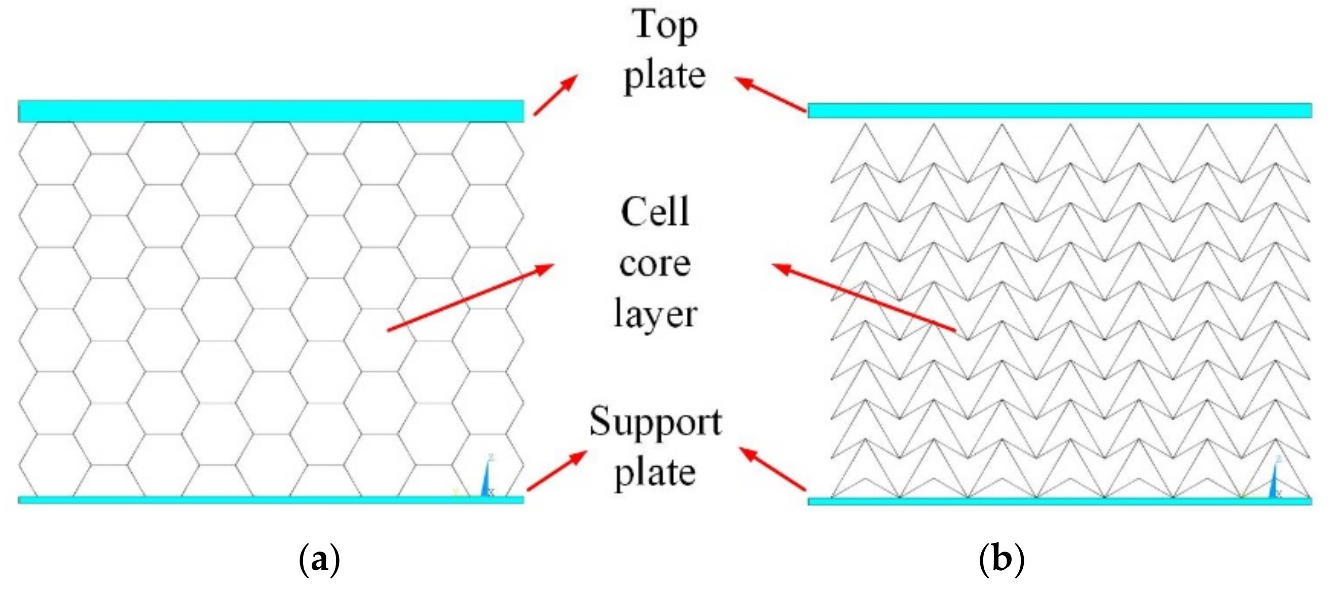
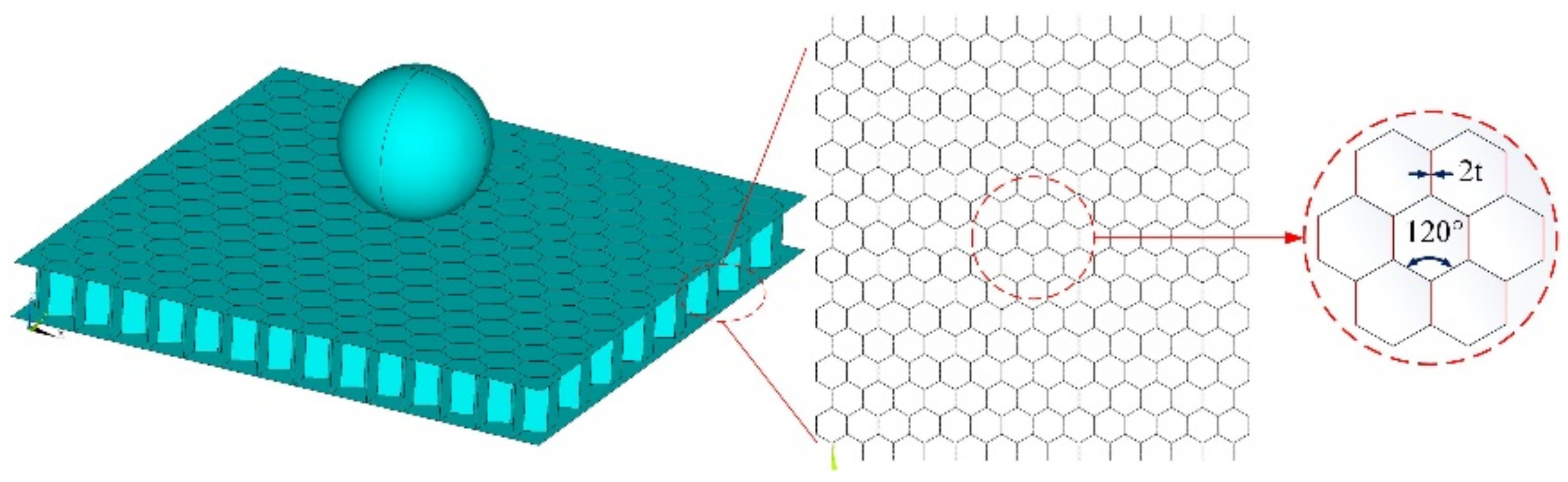
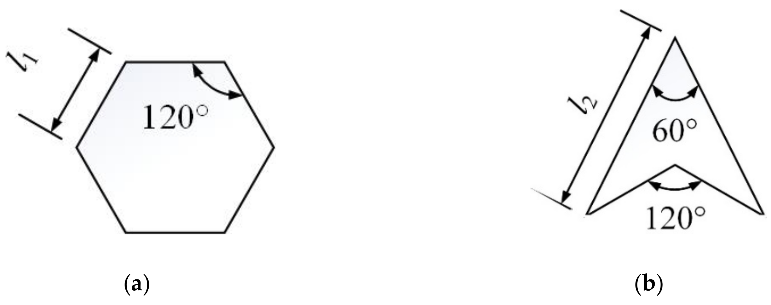
2.1. Description of the Honeycomb Structure

Hexagonal honeycomb and arrow honeycomb are the most commonly applied structures with different cell cores, as shown in Figure 1. In order to understand the performances and failure modes of the two kinds of honeycomb structures under compressive loads, Figure 2 presents the deformations and the collapse modes during the compress progress under the vertical load through the rigid plate with a velocity of 10 m/s.
It can be seen from Figure 2 that, with the increase in impact displacement caused by the plate, obvious deformation in an “X” shape occurs at the cell core layer of the hexagonal honeycomb structure (Figure 2). However, as for the arrow honeycomb structure, an “I” shaped deformation occurs near the top plate and the support plate (Figure 2).

2.2. Conventional Crashworthiness Index

Multiple indicators are adopted to understand the crushing properties and energy absorption performance of the honeycomb, and those crashworthiness indexes used in previous studies mainly focus on crushing force, impact depth and energy absorption, etc. Here, maximum impact depth (δmax) and specific energy absorption (SEA) are adopted.
(1) The maximum impact depth (δmax) serves as a commonly used index to assess the crushing deformation under impact. Once the maximum value is exceeded, the bearing capacity of the collided part will be greatly reduced, and even the failure of the structure will occur. A smaller δmax generally appears on the sandwich structure of stronger crashworthiness.
(2) Specific energy absorption (SEA) is defined as the amount of energy absorbed per unit mass of a honeycomb structure. It can be defined as
SEA = TEA / M
where M is the mass of the honeycomb structure; TEA is the total plastic energy absorption of the honeycomb structure, which can be calculated in Equation (2) according to the principle of energy conservation,
TEA = m 2 ( v 0 2 v r 2 )
where m is the mass of the rigid impactor, v0 is initial velocity of the rigid impactor before impact, and vr is the residual velocity of the rigid impactor after impact.
The higher value of SEA represents the better crashworthiness of sandwich structures.

2.3. Verification of the FE Method for the Simulation of Oblique Collision with Hexagonal Honeycomb Sandwich

2.3.1. Description of the Verified Research

There are many studies on the impact resistance of honeycomb structures, especially on a hexagonal honeycomb sandwich. Wang et al. [28] carried out FE simulations by using the ABAQUS code to study the mechanical behavior of hexagonal honeycomb sandwich structures. In their research, the hexagonal honeycomb sandwich with width W = 150 mm, length L = 1.6 m, wall thickness H = 15 mm and side length h = 6 mm are considered. The sandwich was subjected to the impact of a spherical impactor with diameter D = 40 mm and mass M = 0.3 kg in the oblique direction θ = 45° at the speed of v0 = 15 m/s. The simulated working condition and geometric configuration of the honeycomb core are consistent with Wang [28].

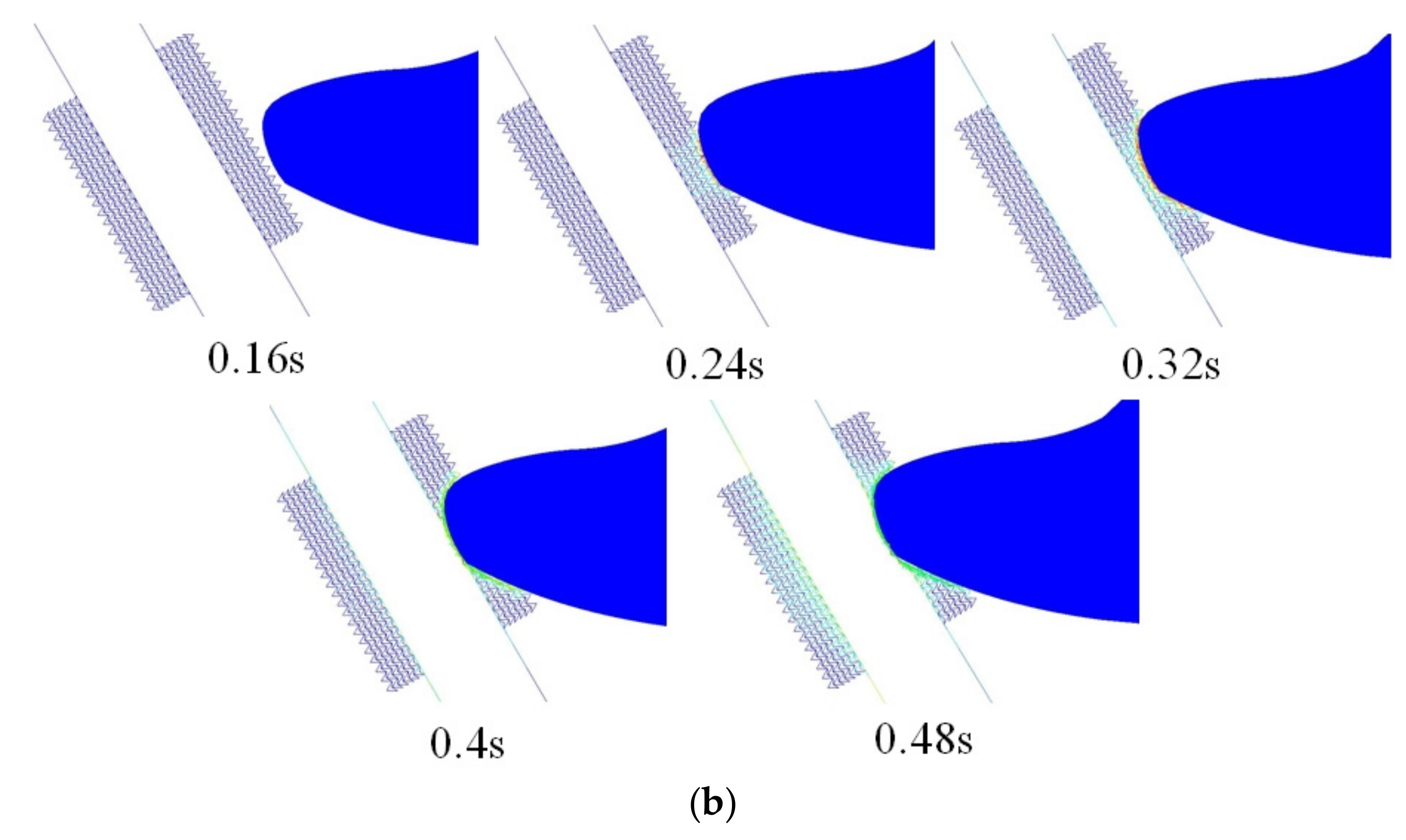
2.3.2. Verification Model of This Study

Here, in order to verify the feasibility of using ANSYS/LS-DYNA to study the impact resistance of honeycomb structure, the verification simulations of the hexagonal honeycomb sandwich under spherical oblique collision are carried out, which are consistent with the research made by Wang et al. (2021) [28].
Figure 3 shows the verification model of this study, which was established by ANSYS/LS-DYNA. The impactor was modeled as a rigid body, and the honeycomb sandwich structure was meshed by using SHELL163 elements. In this study, the isotropic elastic constitutive and perfect plasticity model was adopted as a constitutive model of honeycomb structure which were the same as that adopted in the study of Wang (2021). The material properties of a honeycomb sandwich structure are consistent with Wang [28]. The contact between the impactor and the honeycomb sandwich structure is set as surface to surface automatic contact, with a friction coefficient of 0.3. Fixed constraints are set around the honeycomb sandwich structure.

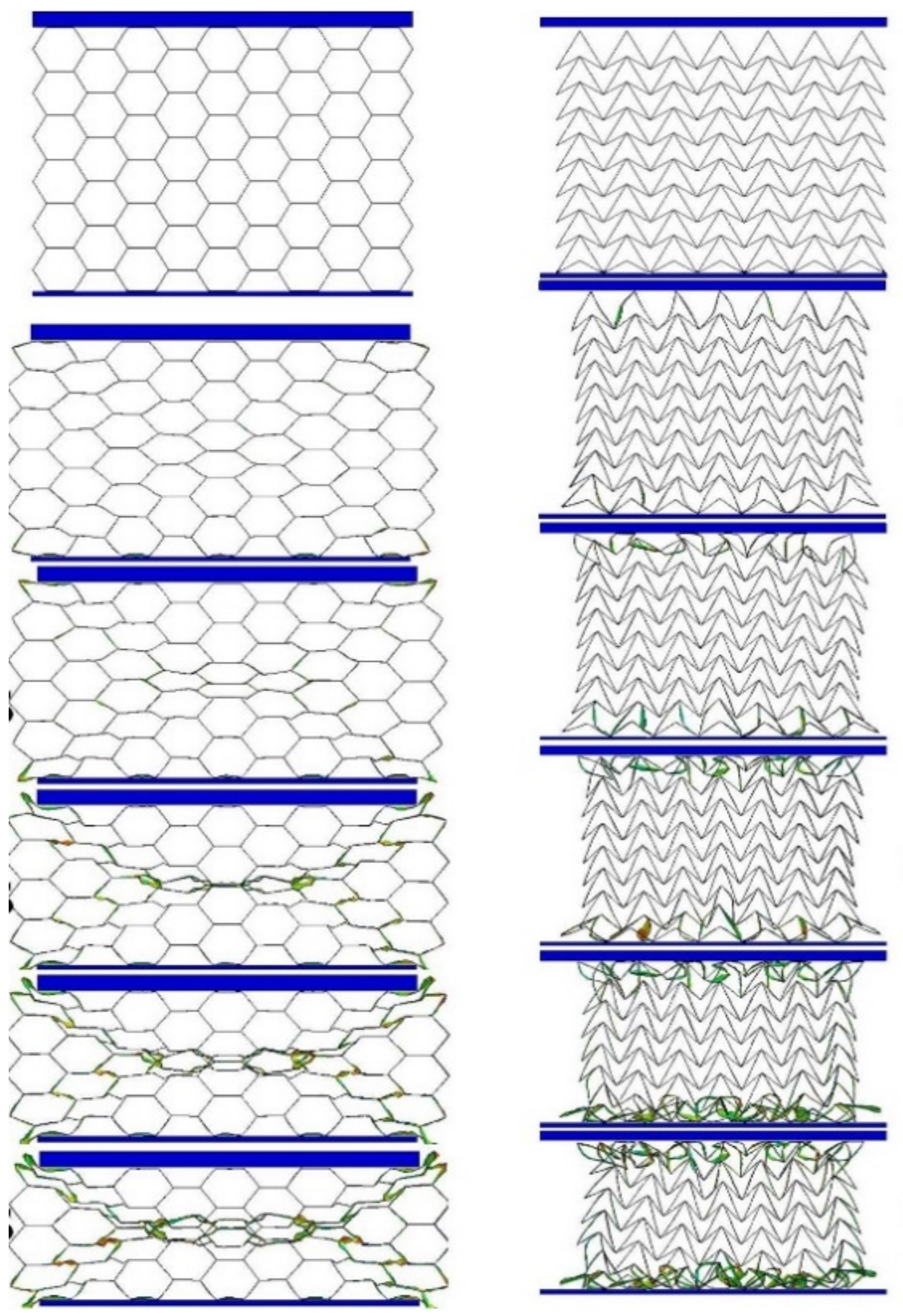
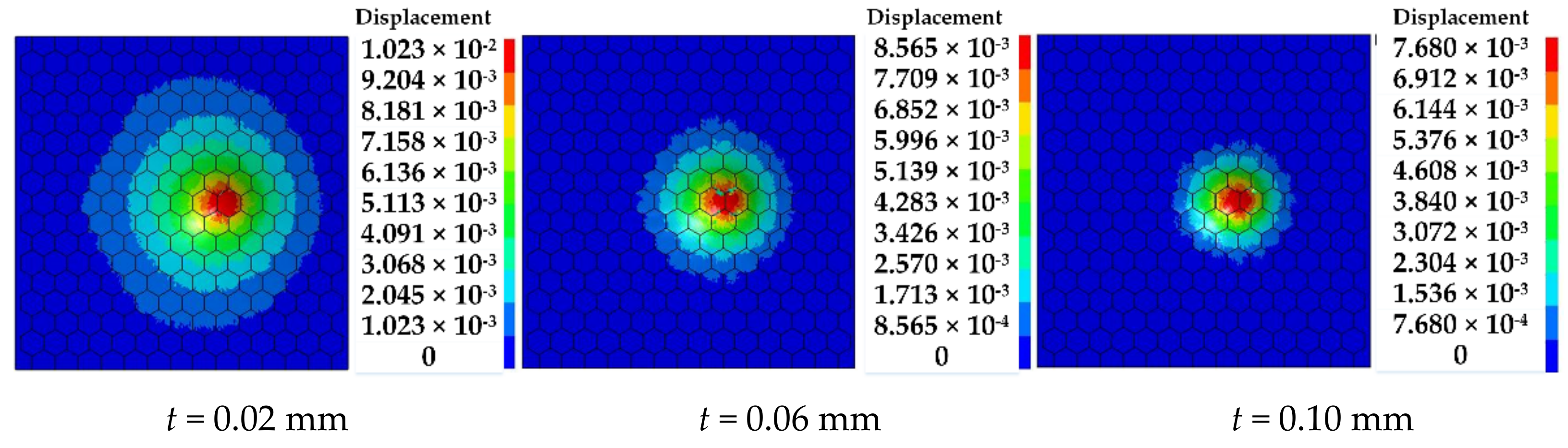
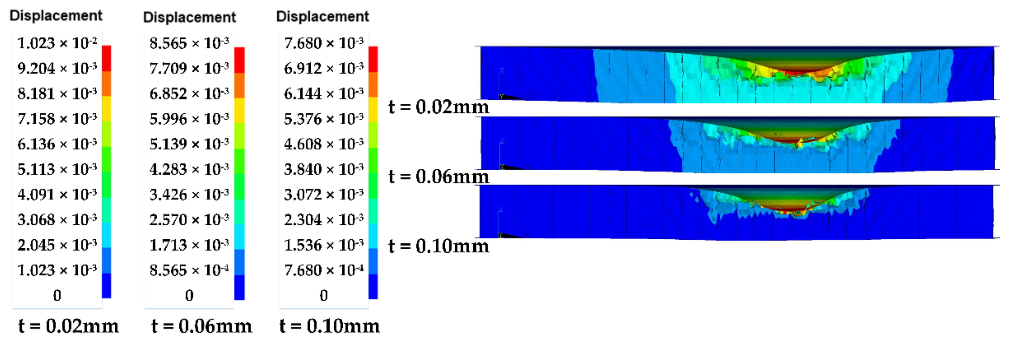
2.3.3. Verification Results Comparison

The simulations of the hexagonal honeycomb sandwich structures with different wall thicknesses t = 0.02 mm, 0.06 mm and 1 mm, were performed, respectively, as assumed by Wang et al. (2021) [28].
Figure 4 shows the deformation contours of the sandwich with three wall thicknesses after an oblique impact at 45°. It can be seen that an asymmetrical dent profile is formed on the surface of the sandwich structure which is consistent with the experimental dent profile reported by Wang 2021 [28] (shown in Figure 6d in [28]).
Figure 5 presents the cross-sectional view of the hexagonal honeycomb structure, and compared the results to that of simulations made by Wang et al. (as shown in Figure 7a in [28]). In can be found that the simulated results of this study are in good agreement with the results of Wang et al. (2021) for three different thicknesses t. The displacement contour shows that the dent depth and dent diameter gradually decrease with the increase in t, which shows similar trends with Figure 7a in [28]. Specifically, when t = 0.02 mm, the dent area accounts for more than half of the whole section, while when t = 0.06 mm, the dent area accounts for 1/3 of the whole section, and when t = 0.10 mm, the dent area is smaller, which is consistent with the results of Wang et al. (2021).
Moreover, the results of the maximum impact depth δmax obtained in this study are listed in Table 1 to be compared with the results of Wang et al. (2021) (listed in Table 4 in [28]), which indicate reasonable agreement. According to Wang et al. (2021), the maximum impact depth of the honeycomb sandwich with thicknesses of 0.02 mm, 0.06 mm and 0.10 mm are 9.12 mm, 7.53 mm and 6.39 mm, respectively. Correspondingly, the error between this study and [28] is 10.6%, 12.1% and 16.8%, respectively, which indicates an acceptable agreement with the reported results [28] considering the different software and meshes.
The SEA is compared to the results of Wang et al., 2021 [28], as listed in Table 2. The max error is 5.7%, which indicates a good agreement with the reported results (listed in Table 4 in [28]). According to Wang et al. (2021), the SEA of a honeycomb sandwich with a thickness of 0.02 mm, 0.06 mm and 0.10 mm are 449.51 J/kg, 404.63 J/kg and 363.96 J/kg, respectively. Correspondingly, the error between this study and [28] are 2.6%, 4.6% and 5.7%, respectively, which indicates an acceptable agreement with the reported results [28] considering the different software and meshes.

3. Numerical Simulation of the Proposed Honeycomb Reinforced Pipes

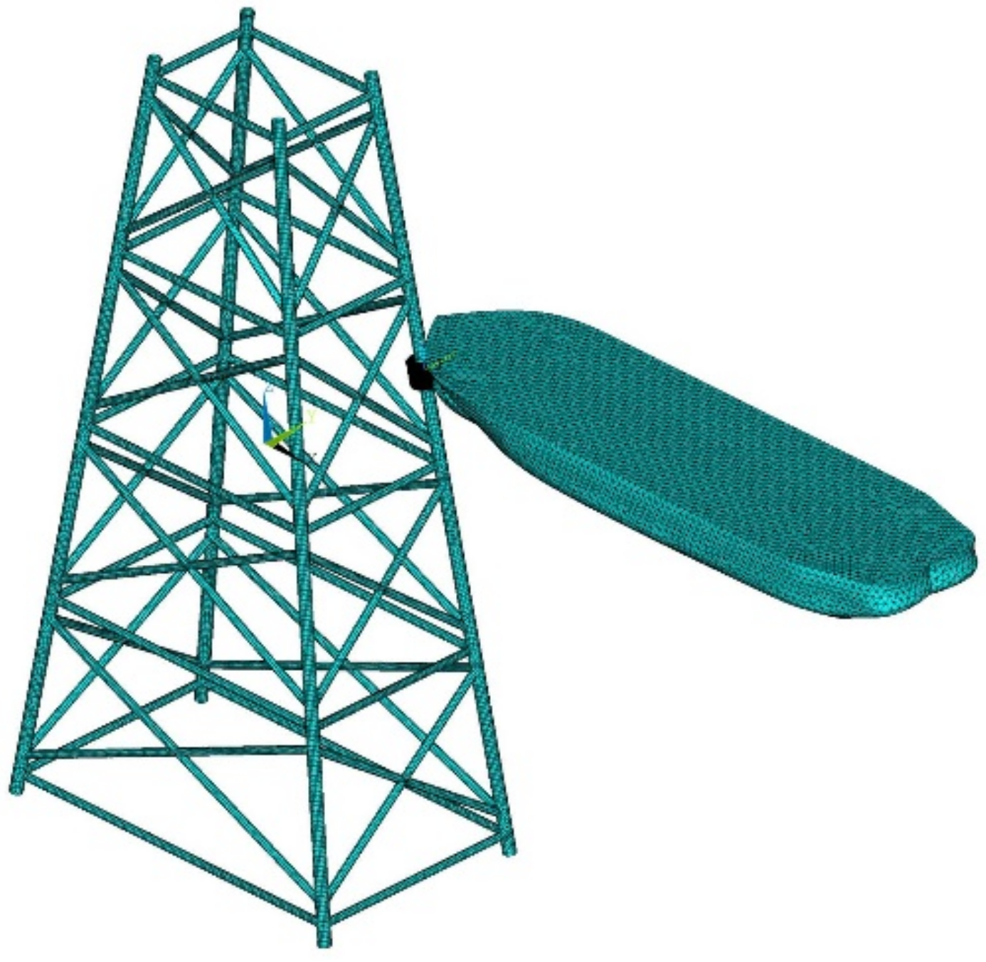
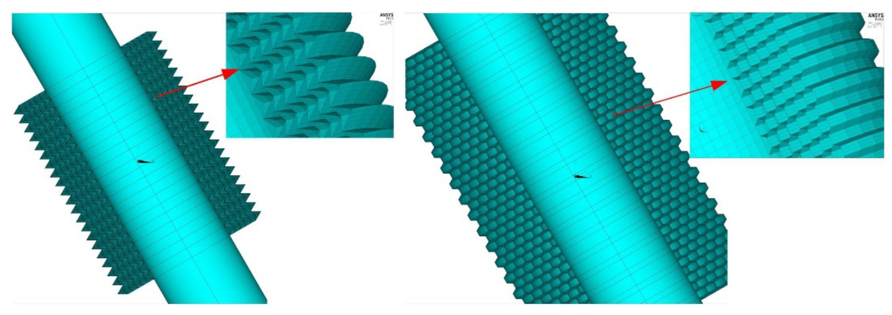
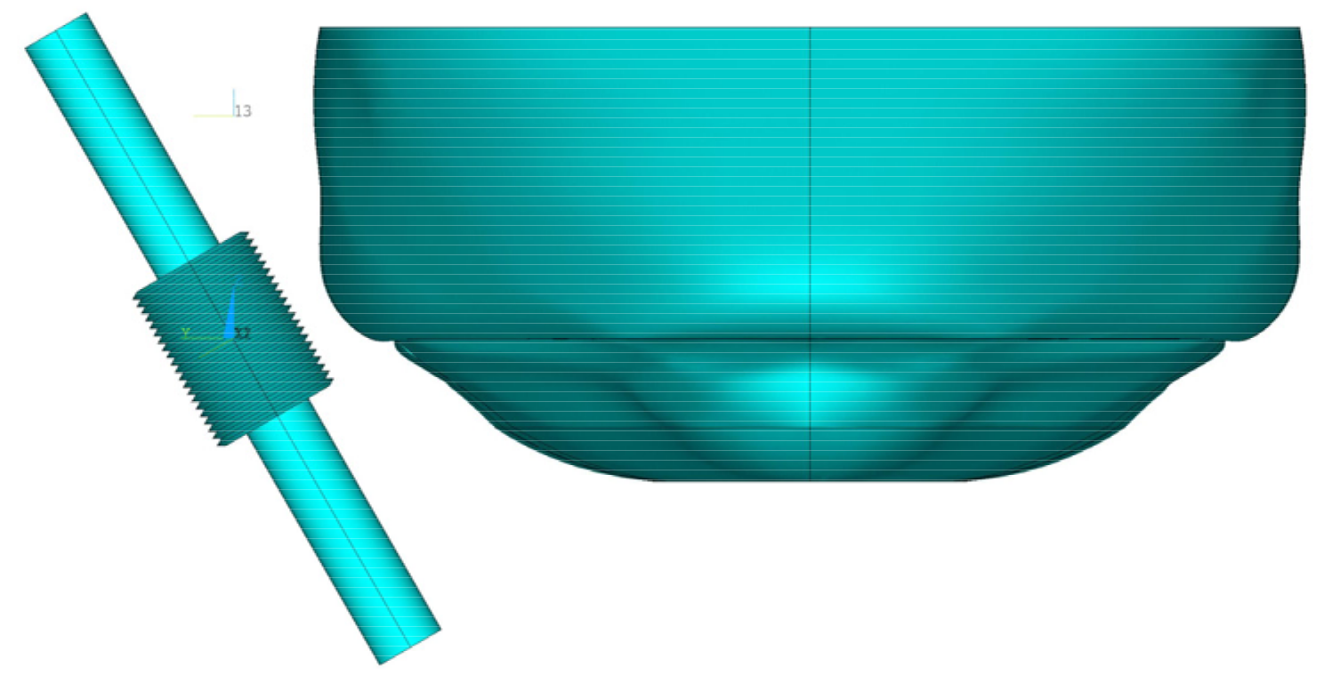
3.1. FE Model of the Proposed Honeycomb Reinforced Pipes

A section of the pile leg in a four-legged jacket platform is taken as an example to conduct FE analysis for ship–platform collision as shown in Figure 6. The pile leg was considered as a pipe with a length L = 8 m, diameter D = 0.8 m, thickness t = 0.075 m. In order to protect the pipe from impacts, honeycomb structures were adopted to reinforce the pipe as shown in Figure 7.
Two types of honeycomb structures, namely hexagonal honeycomb and arrow honeycomb, were adopted to reinforce the pipe, the geometry and the size are shown in Figure 8. In order to compare the results of two different types of honeycomb structure, it is necessary to exclude the influence of cell size, so the method of equal mass was adopted, which means that the quality consistency of the single cell of different cell type is guaranteed. Specifically, first, take the side length of a hexagonal honeycomb as a suitable value (here, it is set to l1 = 0.05 m) and calculated the circumference of the hexagonal honeycomb. Then, the circumference of the arrow honeycomb is set equal to that of hexagonal honeycomb, and thus the side length could be calculated according to the angle. Finally, the designed shapes and sizes of two kinds of cells for this study are shown in Figure 8. The side length of an arrow honeycomb is l2 = 0.095 m, and the wall thickness t = 5 mm. The thickness of the entire honeycomb structure is determined by the number of honeycomb layers, which is set as six layers in this study.
The pipe was modeled using SHELL163 elements. Additionally, the pipes protected by honeycomb structures were modeled by using SHELL163 elements. The “GLUE” connection method was adopted for the honeycomb structure and the connection between the honeycomb structure and the pile leg. Figure 9 shows the FE model of the honeycomb reinforced pipe.
Since the deformation of the ship is not the focus of the study, its geometry is simplified and only the bow is modeled as a rigid body, as shown in Figure 9, the same as what was assumed in Dai et al. (2013) [29] and Moulas et al. (2017) [10]. The bow was meshed by using SOLID164 elements.
In this study, the contact algorithm AUTOMATIC_SURFACE_TO_SURFACE (ASTS) in LS-DYNA was used for the contact between the ship and the pipe, and the penalty-based algorithm is adopted. The dynamic and static friction coefficients associated with the contact interface are set as 0.3, which was the same to Ref. [1]. The added mass effect from ocean waves is taken into account by the coefficient of 1.05 for the head-on-bow collision [16,30].

3.2. Material Model

During the ship–platform collision process, huge collision impact forces normally lead to the plastic deformation of the structure or even causing the material to fracture. Thus, it is also essential to resolve the proper material modeling. The strain rate is directly related to the yield limit of materials and has an important influence on the simulation results. Here, the Cowper–Symonds constitutive model (Cowper et al., 1957 [31]; Storheim et al., 2015 [32].) is used to describe the plastic strain hardening of structure steel, which can reflect the strain rate effect as follows:
σ y = 1 + ε ˙ C 1 p ( σ 0 + E p ε p e f f )
E p = E tan E E E tan
where is σ 0 the initial yield stress, ε ˙ is the strain rate, ε p e f f is the effective plastic strain, E p is the plastic hardening modulus and C and P are the strain rate parameters, respectively. Failure strain (εf) was set to 0.2, which is has been accepted in current studies, and the other parameters are shown in Table 3. Here, the material model adopted in LS-DYNA for Cowper-Symonds model was MAT003_PLASTIC_KINEMATIC [33].
Aluminum A5052 [34,35], the most commonly used metal material for honeycomb structure is adopted as the honeycomb structure material in this paper, which displays a good feature of corrosion resistance for the offshore structures as reported by Kaya (2018) [35]. The constitutive model adopted is consistent with the Cowper–Symonds constitutive model adopted for pile-leg steel pipe, and its properties are shown in Table 4.

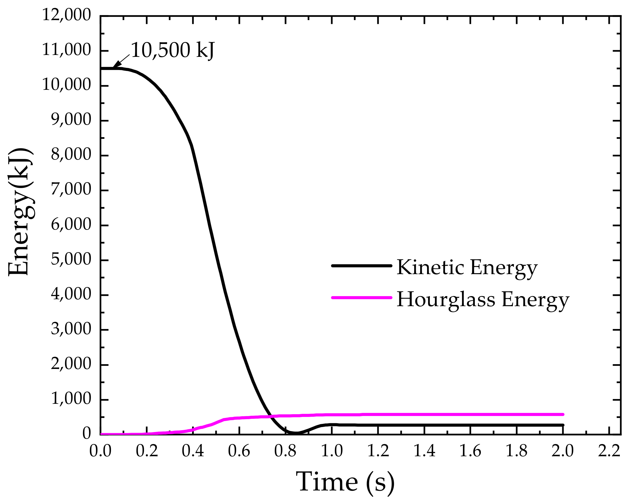
3.3. Collision Scenarios

The actual circumstance of an impacting accident is very complex, which include the velocity and angle of impacting ships. According to DNV-RP-C204(2010), the design collision event, which considered the impact from a standard supply vessel with a displacement of 5000 tons and a speed of 2 m/s, has been used for decades.
Head-on-bow collisions between ship and platform pipes are among the most common accidents. Here, bow collisions including head on and oblique collision were assumed, with the ship impact angles were set to 0°, 15°, 30°, 45° and 60°, respectively, to analyze the influence of the impact angle as shown in Figure 10. In addition, the ship collision speeds are set from 0.5 m/s to 2.0 m/s. Thus, the multiple collision scenarios are set as shown in Table 5.

4. Results

4.1. Response of Honeycomb Reinforced Pipe under the Ship Impact

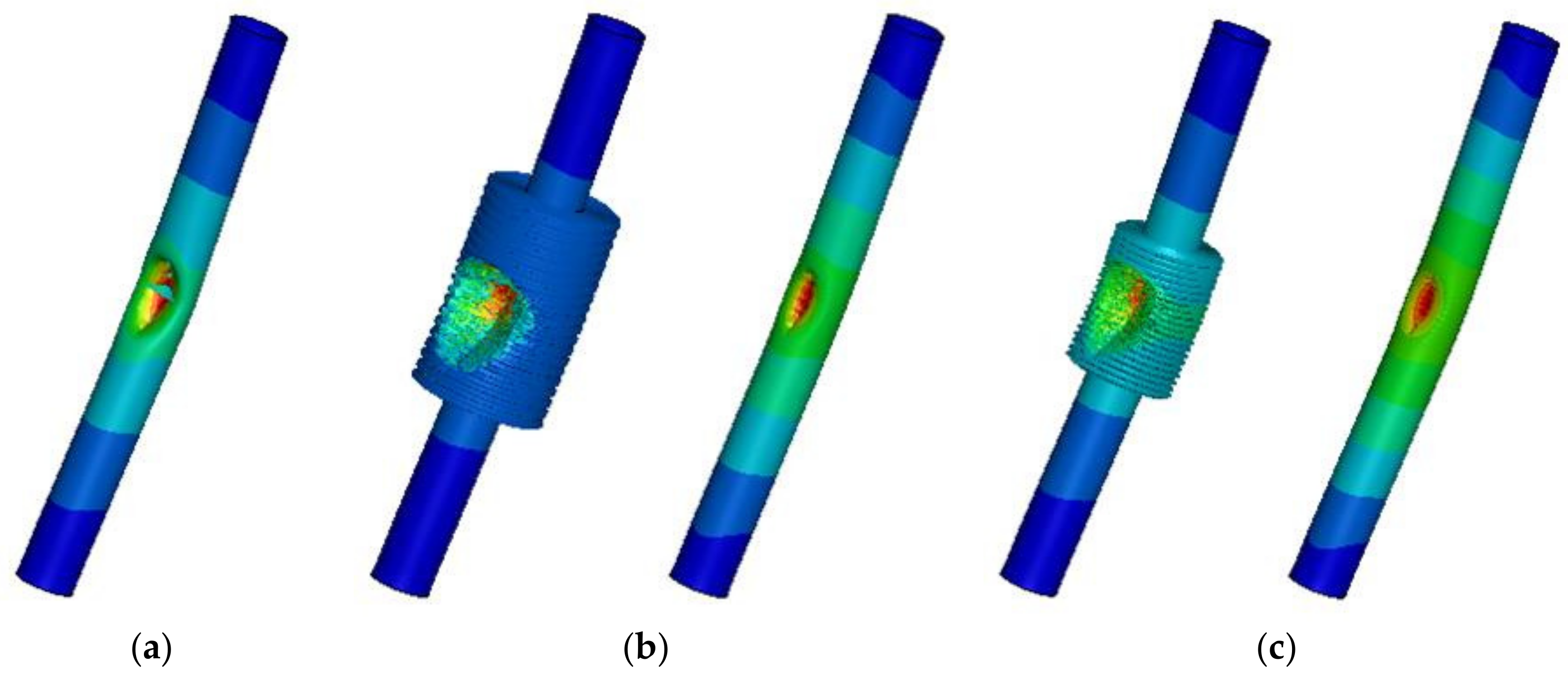
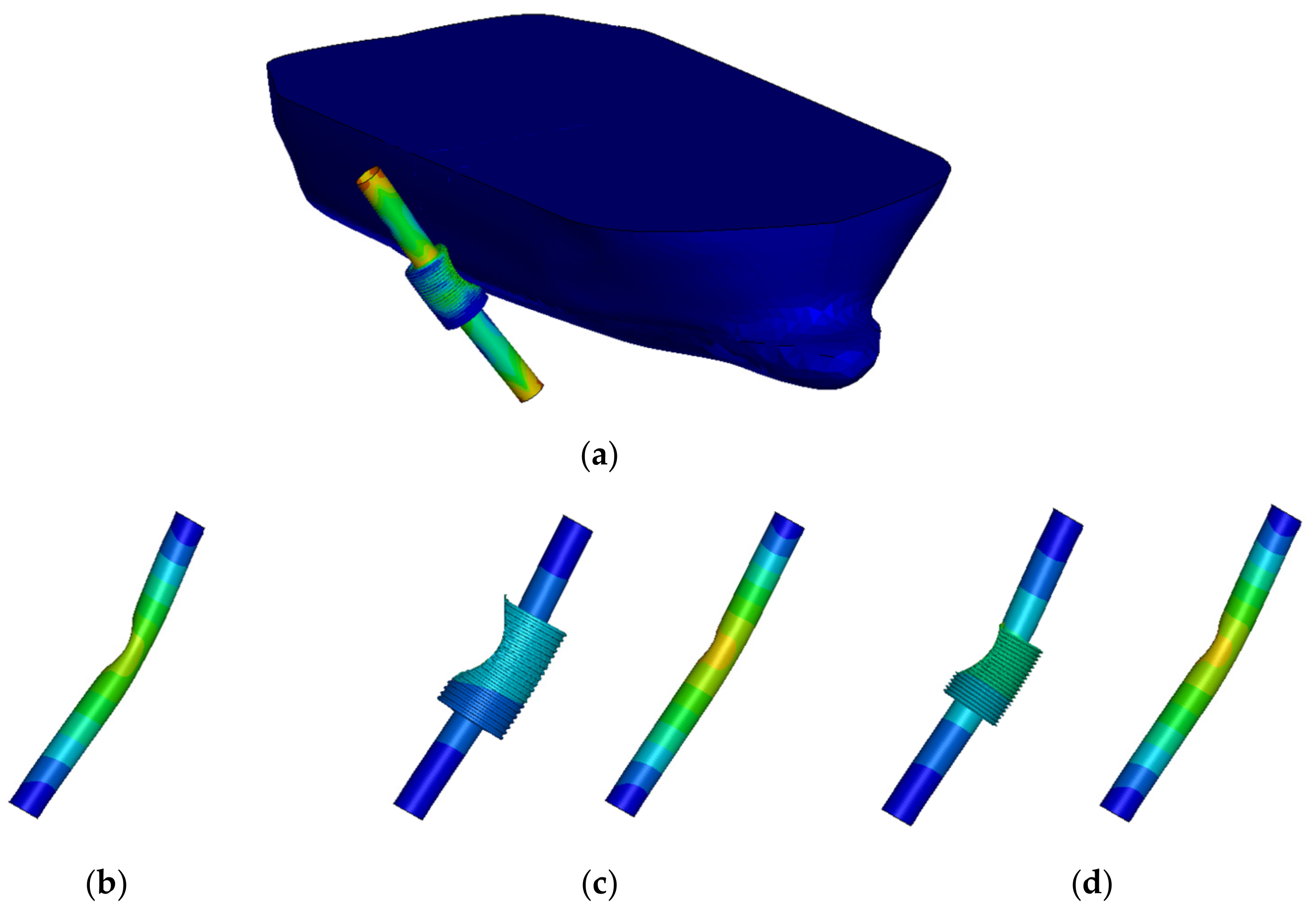
4.1.1. Deformation of the Unprotected and Honeycomb Reinforced Pipes

Figure 11 presents the deformation of the pile leg under ship collision at the collision speed of 2 m/s. In order to give a clear illustration of the effects of honeycomb reinforcement on the mechanical response of the pile leg, it is necessary to compare the energy absorption performance and deformation mode of a honeycomb structure with different cell types.
Figure 12 presents the deformation contours of the unreinforced pipe, the hexagonal honeycomb reinforced pipe and the arrow honeycomb reinforced pipe, respectively. It can be seen from Figure 12a that severe deformation and even a fracture occurred in the unprotected pipe due to the intense impact force caused by ship collision. However, the deformation of the pipes with honeycomb reinforcements are slight (shown in Figure 12b,c). It can be concluded that both the hexagonal honeycomb structure and the arrow honeycomb structure play a great role in the reinforcement of the pipe under ship collision.
According to the simulated results during the collision process, the collision force–indentation curves are shown in Figure 13. This shows that the maximum impact depth of the honeycomb reinforced pipes is significantly smaller than that of the unprotected pipe, which demonstrates the effect of honeycomb structure on improving the impact resistance of the pipe. Comparing the two curves of both honeycomb reinforced pipes, it was found that the value of the peak crash force and the maximum impact depth of the hexagonal honeycomb reinforced pipe is smaller than that of the arrow honeycomb reinforced pipe, which means that the hexagonal honeycomb structure has a better anti-impact ability.
Moreover, the energy curve in the whole process of collision of the pipe reinforced by a hexagonal honeycomb structure is plotted in Figure 14. It could be seen that the kinetic energy and the hourglass energy in the collision process become to a stable state after 1.0 s, indicating the convergence of the energy absorption. Additionally, the kinetic energy could be calculated as follows
E = 1 2 × c a d d × M s h i p × v 2
where E is the kinetic energy, v is the collision velocity, Mship is the mass of the ship and cadd is the coefficient of added mass which could be set as 1.05 for head-on-bow collisions. According to Equation (5), the kinetic energy at the initial stage for this collision scenario should be 10,500 kJ, which is the same as the FE simulation result shown in Figure 14.

4.1.2. Folding of the Honeycomb Structures

Figure 15 presents the cross-section vies of the two honeycomb reinforced pipes during the progress of the collision. It can be seen that the folding of cellular cells occurs due to large deformation caused by collision for both types of the cellular structures. Additionally, it can be found that the folding phenomenon of the hexagonal honeycomb starts a little earlier than that of the arrow honeycomb.

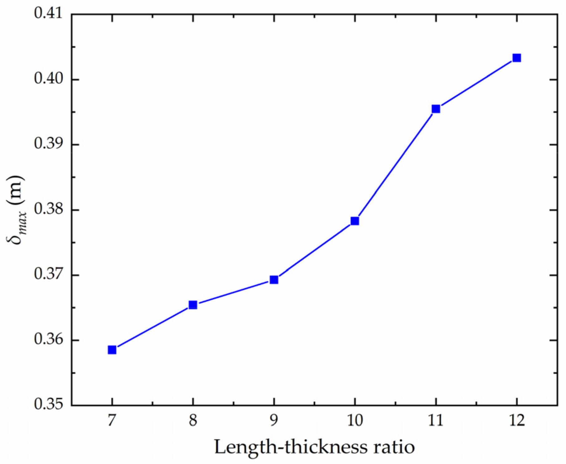
4.1.3. Influence of Length–Thickness Ratio on the Collision Resistance

In order to study the effect of the side length and wall thickness of a honeycomb cell (shown in Figure 8) on the collision resistance, the length–thickness ratio was defined as l1/t. Then, the influence of this ratio on the collision response and resistance of the hexagonal honeycomb reinforced pipe was analyzed in this section. The maximum impact depth δmax of different length–thickness ratios were calculated, and the curves of the δmax ratio are drawn in Figure 16. It could be seen that the maximum collision depth δmax of the pipe gradually increases with the increase in the length–thickness ratio. This means that when the side length of the honeycomb cell decreases or the wall thickness increases, the hexagonal honeycomb structure will have a better capacity for collision resistance.

4.2. Evaluation of Crashworthiness under Different Collision Velocities

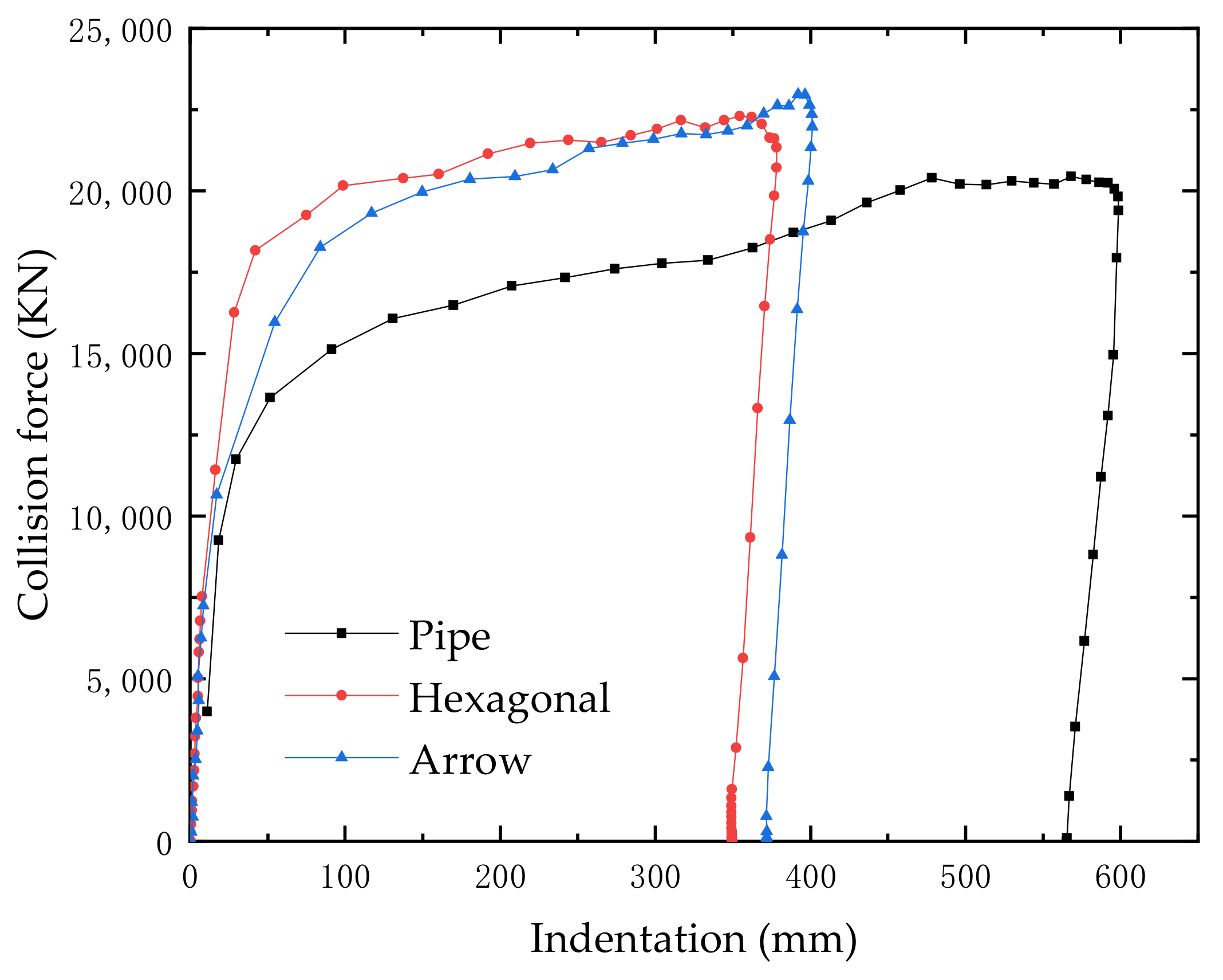
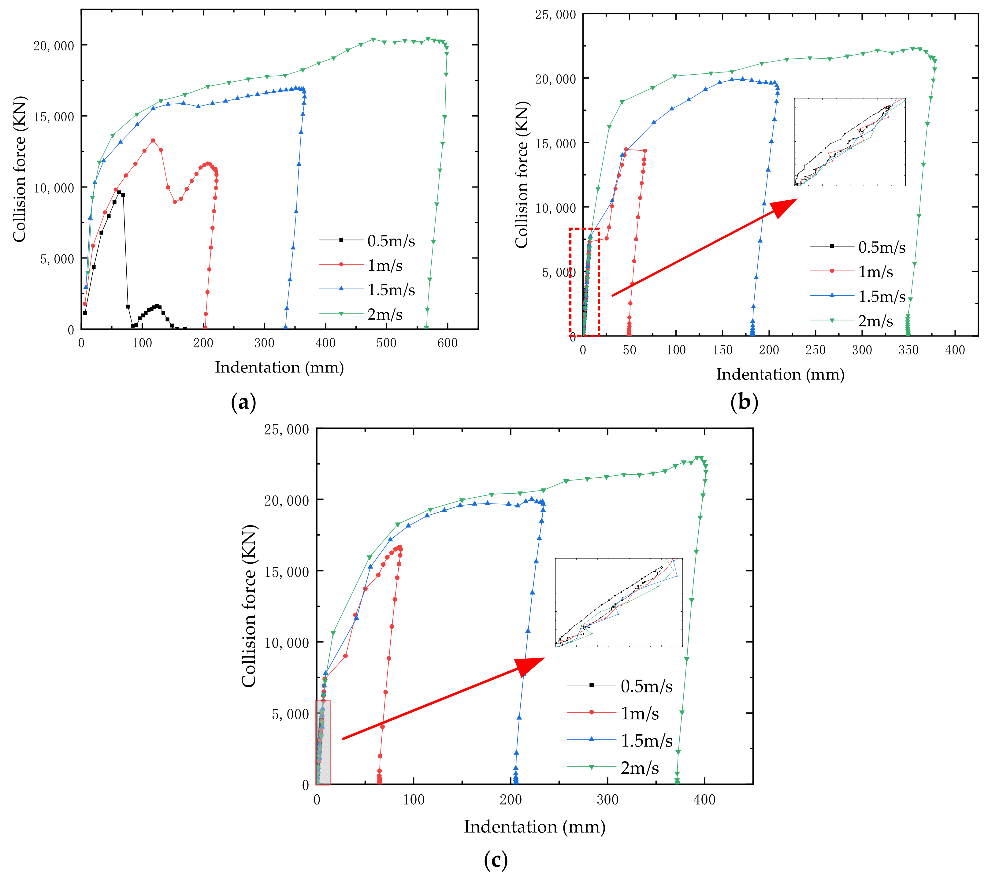
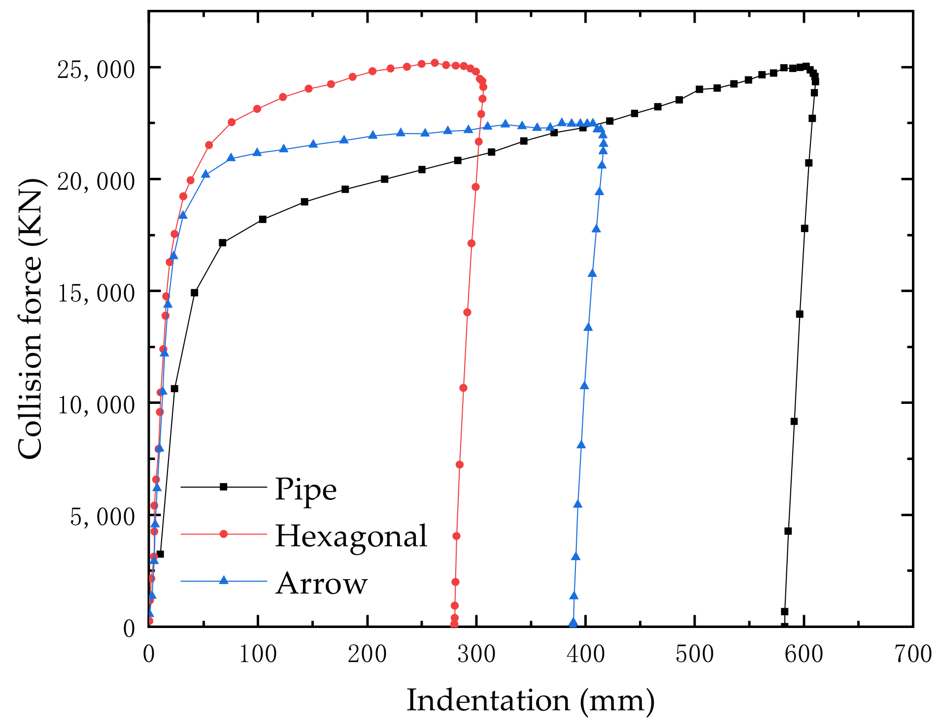
4.2.1. Collision Force–Indentation Cures

The collision force–indentation cures of the pipes under different collision velocities are plotted in Figure 17. By comparing Figure 17a–c, it can be found that the peak collision force gradually increases with the increase in impact velocity. Additionally, the max displacement significantly increases with the increase in the impact speed.
It is known that a smooth collision force–displacement curve indicates that the structure has a good impact resistance. It could be seen from Figure 17 that a significant fluctuation due to the rebound occurs in the unprotected pipe at low velocity of 0.5/s and 1 m/s, however, no rebound phenomenon occurs in the reinforced pipe, which demonstrates a good energy absorption ability of the honeycomb structure.

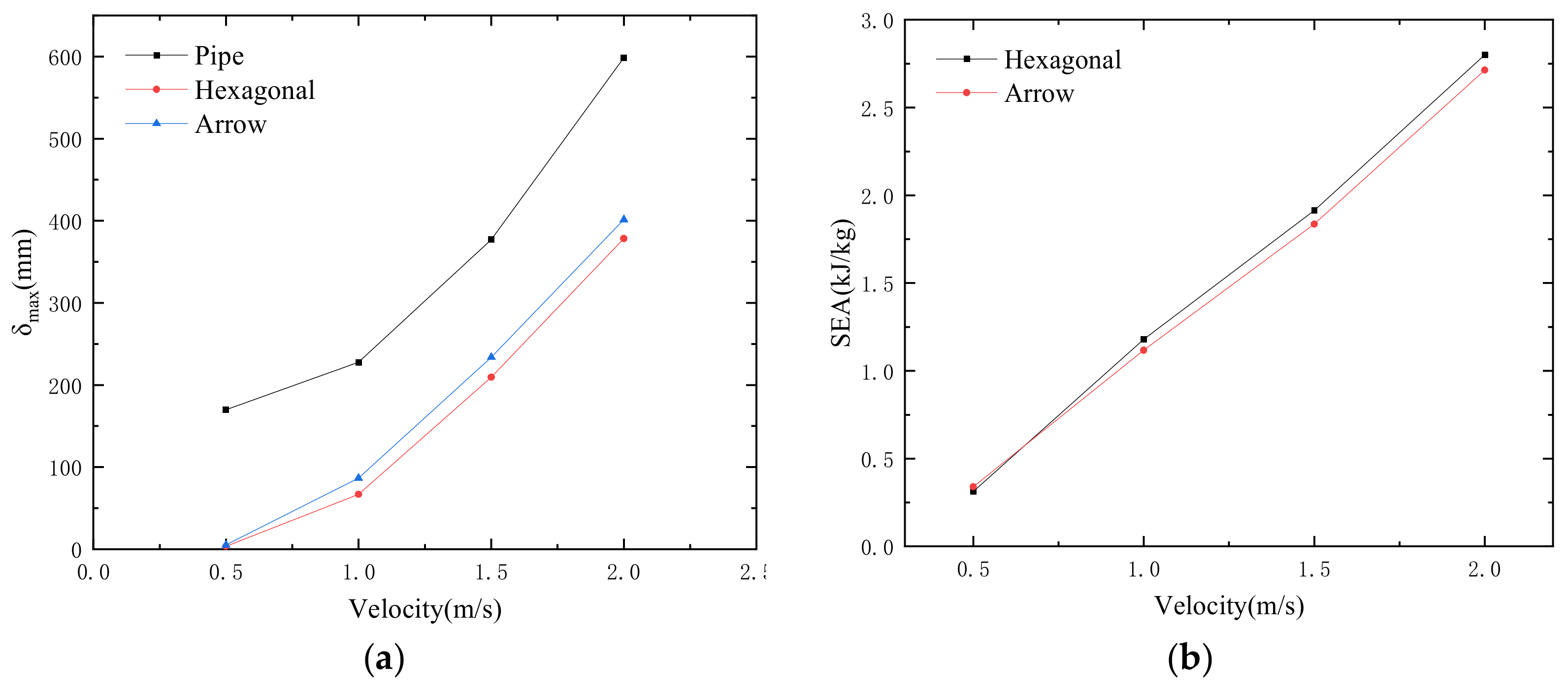
4.2.2. Results of Crashworthiness Indexes

The crashworthiness indexes including the δmax and SEA of the three structures were calculated, and the results are listed in Table 6. Additionally, the δmax–velocity curves and SEA–velocity curves are plotted in Figure 18a and Figure 18b, respectively.
As shown in Figure 18a, the δmax of the protected pipe dramatically decreased through the protection of the honeycomb reinforcement. Comparing the two types of honeycomb structures, it could be found that the δmax of the hexagonal honeycomb enhanced pipe is a little smaller than that of the arrow honeycomb protected pipe. This proves that the hexagonal honeycomb could provide better protection to the pipe under ship collision than the arrow honeycomb.
As shown in Figure 18b, at a slow impact speed of 0.5 m/s, the value of SEA of arrow honeycomb structure is slightly greater than that of the hexagonal honeycomb structure. However, when the impact speed is greater than 0.5 m/s, the value of SEA of the hexagonal honeycomb structure is bigger than that of the arrow honeycomb structure. Thus, it could be concluded that in most of the collision cases, the hexagonal honeycomb structure has a better performance in energy absorption efficiency than that of the arrow honeycomb structure, while at a very low speed of 0.5 m/s, it is just the opposite.

5. Discussion

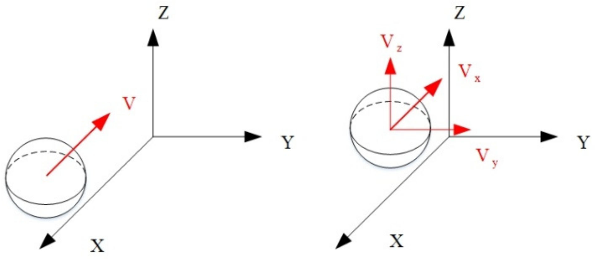
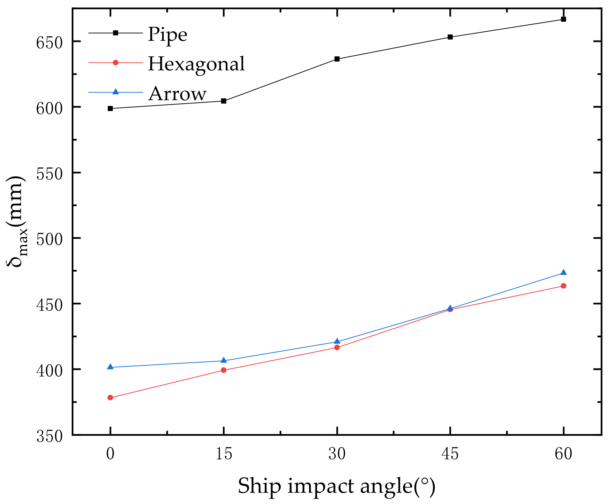
5.1. Influence of the Ship Impact Angle

As stated above, most of ship–platform collision accidents occurred at the pile legs or braces of the offshore platform. However, it is usually an oblique collision due to the fact that the pipe legs of the jacket platform are inclined fixed into the seabed as shown in Figure 19. The impact angle θ is defined as the angle between the normal direction of pipe and impacting the direction of the ship, as shown in Figure 19. Here, the ship impact angles were set as 0°, 15°, 30°, 45° and 60°, respectively, to analyze the influence of the impact angle.
The contours of an effective plastic strain of the reinforced pipes at different impact angles are plotted in Figure 20. It can be seen that the deformation is obviously different at different impact angles due to the offset or the slippage caused by the contact with the ship.

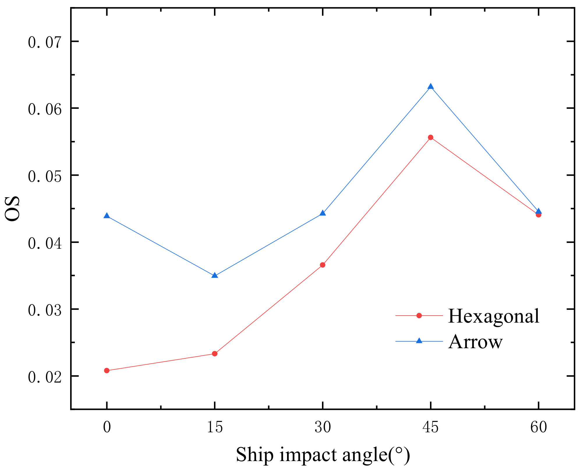
5.2. The Proposed Crashworthiness Index of Offset Sliding (OS)

As discussed in Section 4.2, the maximum impact depth (δmax) and specific energy absorption (SEA) were adopted to study the impact resistance of the two kinds of honeycomb structures, which could interpret the deformation and the energy absorption of the honeycomb structures.
However, since the impacted structures are tubular pipes and the honeycomb structures are wrapped surrounding the pipes, an offset sliding will occur when obliquely impacted by the ship. In other words, an asymmetrical dent is formed on the honeycomb structure under oblique impact. However, the previous indexes cannot describe this asymmetrical feature. Therefore, a crashworthiness index, namely offset sliding (OS), is proposed in this paper. The calculation formula of offset sliding (OS) is:
OS = v y 2 + v z 2 / V
where v y , v z are the velocities deviated from the velocity of the impactor after collision, and V is the velocity of the impactor before collision, as shown in Figure 21.
According to the calculation formula of offset sliding (OS), this reflects the sliding offset the original direction of the ship, which will be a supplement to the previous crashworthiness indexes. The lower the value of OS, the better the crashworthiness of the honeycomb structure.

5.3. Evaluation of Crashworthiness under Different Collision Angles

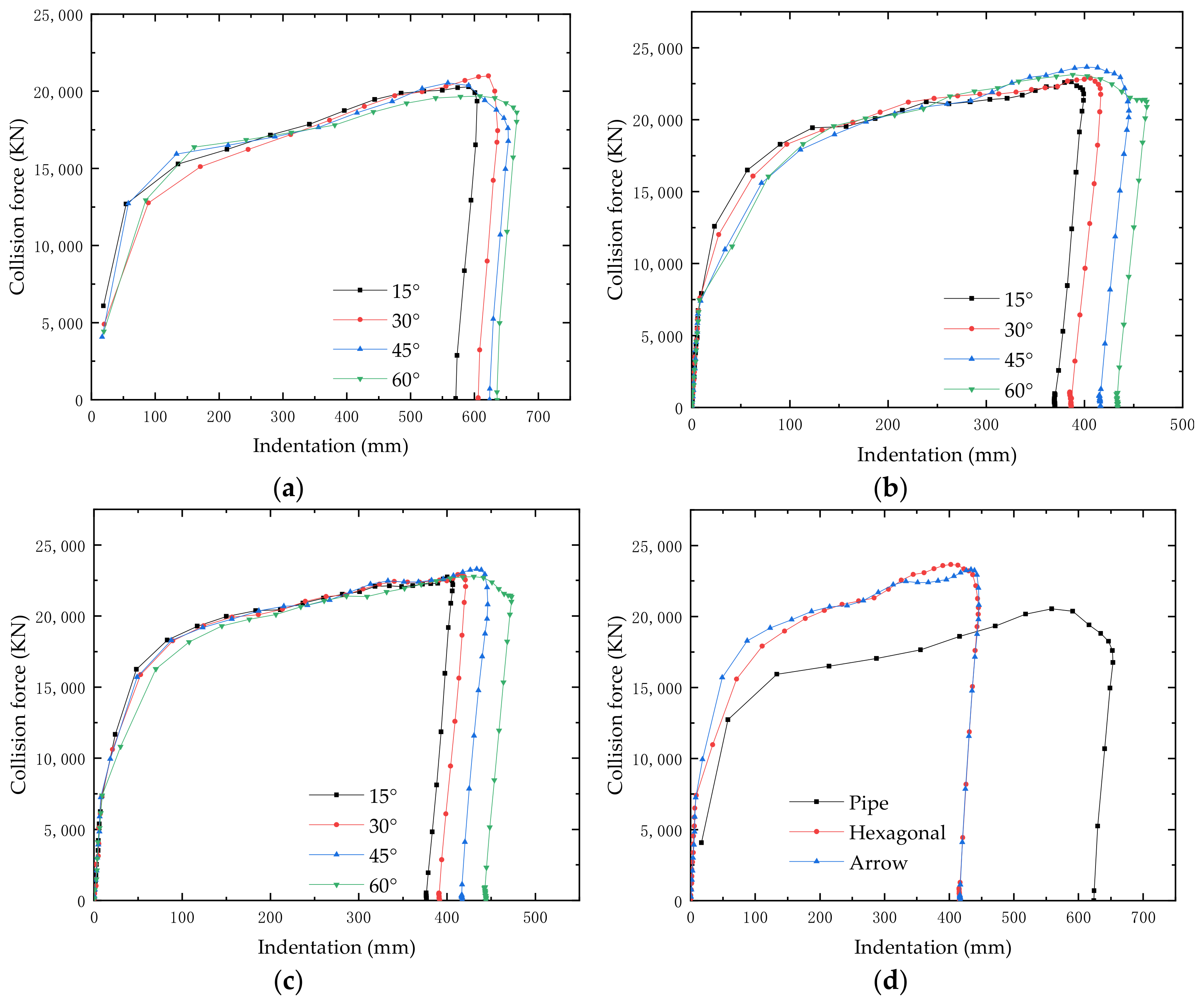
5.3.1. Collision Force–Indentation Cures

The collision force–indentation curves of a different impact angle for the unreinforced pipe, the hexagonal honeycomb reinforced pipe and the arrow honeycomb reinforced pipe are, respectively, drawn in Figure 22a–c. It can be seen that the collision force–indentation curves of different angles are almost consistent in the loading stage. However, in the unloading stage, the smaller the ship impact angle, the smaller the indentation.
Additionally, the impact angle of 45° was selected to study the difference of the unreinforced pipe and the reinforced pipe. The collision force–indentation curves are plotted in Figure 22d. It can be seen that, under this impact angle, the displacement of honeycomb reinforced pipe is significantly smaller than that of un-protected pipe. However, the displacement of the two different honeycomb reinforced pipes is almost the same.

5.3.2. Results of Crashworthiness Indexes

The crashworthiness indexes including the δmax and SEA of the three structures were calculated, and were listed in Table 7. Additionally, the δmaxθ curves, SEA–θ curves and OS–θ curves are plotted in Figure 23, Figure 24 and Figure 25, respectively.
As shown in Figure 23, the maximum depth δmax of the protected pipe dramatically decreased through the protection of the honeycomb reinforcement. Additionally, δmax increases with the increase in θ for all the unprotected pipe, the hexagonal honeycomb protected pipe and the arrow honeycomb protected pipe. Comparing the δmax of the hexagonal honeycomb and that of the arrow honeycomb, it could be concluded that the hexagonal honeycomb structure has a better crashworthiness, since it has a lower value of δmax.
According to the definition of SEA, a higher SEA indicates a higher energy-absorbing efficiency of a structure. We plotted SEA–θ curves for both the hexagonal honeycomb structure and arrow honeycomb structure in Figure 24. It can be seen that the SEA of the hexagonal honeycomb structure is larger than that of the arrow honeycomb structure, which proves that the former structure has a better crashworthiness under all the impact angles.
Figure 25 presents the OS–θ curves of the hexagonal honeycomb structure and the arrow honeycomb structure at different angles. It can be seen in Figure 23 that the values of OS of hexagonal honeycomb structure are lower than that of the arrow honeycomb structure, which indicates that the sliding generated by the ship impacts is smaller for the hexagonal honeycomb reinforced pipe. Comparing the two structures, it can be seen that the hexagonal honeycomb can better restrain the ship’s sliding during collision.
As discussed above, the conversional index of δmax and SEA and the proposed index OS could give a consistent evaluation of the crashworthiness of the hexagonal honeycomb structure and the arrow honeycomb structure at different angles. The results prove the rationality of the proposed index.

5.4. Influence of the Side Collision

The effect of the striker header shape usually plays an important role in the dynamic response of the pipe as reported by Do et al. [36]. In order to analyze the influence of different striker header shapes, the side collision scenario was considered, and the corresponding numerical simulations were carried out in this section. Figure 26 shows the FE model of side collision between the ship and the pipe. Additionally, the collision between the ship and three different pipes, including the unreinforced pipe, hexagonal honeycomb reinforced pipe and arrow honeycomb reinforced pipe, respectively, were simulated. The collision velocity is 2.0 m/s, and the material model and the detailed FE model of the pipes are identical to those adopted in Section 3.
Figure 27 presents the deformation contours of the unreinforced pipe, the hexagonal honeycomb reinforced pipe, the arrow honeycomb reinforced pipe. It could be seen that, the honeycomb structure could also protect the pipe under side collision. In contrast to the head-on-bow collision, the value of the collision force on the arrow honeycomb reinforced pipe is much smaller than that of bow collision, while the value of the collision force on the un-protected pipe and the hexagonal honeycomb reinforced pipe is much larger than that of bow collision, as shown in Figure 28.

6. Conclusions

In this paper, two different kinds of honeycomb structure, namely hexagonal honeycomb structure and arrow honeycomb structure, were constructed in order to reinforce the inclined pipe of the offshore platform in case of a collision caused by a ship. The FE models of the ship and designed honeycomb protected pipes were firstly validated using the numerical simulation software ANSYS/LS-DYNA. Then, the simulations were carried out on the FE models considering various influential parameters, including the impact velocity, impact direction and impact position of the ship and the length–thickness ratio of the honeycomb cell to investigate the dynamical performance of the different honeycomb reinforced pipe. Finally, the crashworthiness indexes including the conventional index (δmax and SEA) and the proposed index OS were adopted to evaluate the crashworthiness of the honeycomb reinforced pipe. The conclusions of this paper are as follows:
(1) Both the hexagonal honeycomb reinforced pipes and the arrow honeycomb reinforced pipes have good resistance to ship impact. The hexagonal honeycomb has a better energy absorption ability than the arrow honeycomb, and also produces a better reduction in damage to the pipe after ship impact.
(2) Ship impact velocity and impact angle have obvious influences on the collision consequences. A greater impact velocity indicates greater damage; also, a greater impact angle indicates greater damage. However, the energy absorption efficiencies of both the hexagonal honeycomb and arrow honeycomb structures increase with the impact velocity, but decrease with the impact angle. At the impact angle of 45°, both honeycomb structures have their worst sliding resistance.
(3) The proposed crashworthiness index OS is able to capture the oblique crashworthiness of the honeycomb reinforced pipe well. Additionally, the proposed index OS and the conventional indexes, i.e., δmax and SEA, are consistent in evaluating the crashworthiness of honeycomb structures.

Author Contributions

Conceptualization, H.L. (Hong Lin) and C.H.; methodology, H.L. (Hong Lin) and C.H.; software, H.L. (Hong Lin), C.H. and L.Y.; validation, H.L. (Haochen Luan), P.H., H.X. and S.Z.; investigation, L.Y. and H.L. (Hong Lin); writing—original draft preparation, H.L. (Hong Lin) and C.H.; writing—review and editing, H.K. and L.Y.; supervision, H.L. (Hong Lin); project administration, H.L. (Hong Lin) and L.Y.; funding acquisition, H.L. (Hong Lin). All authors have read and agreed to the published version of the manuscript.

Funding

This research was funded by the National Natural Science Foundation of China, grant No. 51879272, No. 52111530036; and the Fundamental Research Funds for the Central Universities, China, grant No. 22CX03022A.

Institutional Review Board Statement

Not applicable.

Informed Consent Statement

Not applicable.

Data Availability Statement

Not applicable.

Conflicts of Interest

The authors declare no conflict of interest.

References

  1. Yu, Z.; Amdahl, J. A review of structural responses and design of offshore tubular structures subjected to ship impacts. Ocean Eng. 2018, 154, 177–203. [Google Scholar] [CrossRef]
  2. Mujeeb-Ahmed, M.P.; Seo, J.K.; Paik, J.K. Probabilistic approach for collision risk analysis of powered vessel with offshore platforms. Ocean Eng. 2018, 151, 206–221. [Google Scholar] [CrossRef]
  3. Mujeeb-Ahmed, M.P.; Paik, J.K. A probabilistic approach to determine design loads for collision between an offshore supply vessel and offshore installations. Ocean Eng. 2019, 173, 358–374. [Google Scholar] [CrossRef]
  4. PSA (The Petroleum Safety Authority Norway). Investigation Report Following Collision between Big Orange XVIII and Ekofisk 2/4-W. In The Petroleum Safety Authority Norway; Investigation Report; Petroleum Safety Authority Norway: Stavanger, Norway, 2009. [Google Scholar]
  5. NORSOK N-003; Actions and Action Effects. NORSOK Standard N-003 REV; Standards Norway: Lysaker, Norway, 1999.
  6. ISO 19902:2007(E); Petroleum and Natural Gas Industries—Fixed Steel Offshore Structures. First Edition; The International Organization for Standardization: Geneva, Switzerland, 2007.
  7. DNVGL-RP-C204. Design Against Accidental Loads. Norway. Edition August 2017. Available online: https://standards.globalspec.com/std/10183659/dnvgl-rp-c204 (accessed on 20 August 2022).
  8. American Petroleum Institute. API Recommended Practice 2A-WSD (RP 2A-WSD) Errata and Supplement 3; American Petroleum Institute: Washington, DC, USA, 2007. [Google Scholar]
  9. Liu, X.; Jiang, D.; Liufu, K.; Fu, J.; Liu, Q.; Li, Q. Numerical investigation into impact responses of an offshore wind turbine jacket foundation subjected to ship collision. Ocean Eng. 2022, 248, 110825. [Google Scholar] [CrossRef]
  10. Moulas, D.; Shafiee, M.; Mehmanparast, A. Damage analysis of ship collisions with offshore wind turbine foundations. Ocean Eng. 2017, 143, 149–162. [Google Scholar] [CrossRef]
  11. Sun, B.; Hu, Z.; Wang, G. An analytical method for predicting the ship side structure response in raked bow collisions. Mar. Struct. 2015, 41, 288–311. [Google Scholar] [CrossRef]
  12. Rigueiro, C.; Ribeiro, J.; Santiago, A. Numerical assessment of the behaviour of a fixed offshore platform subjected to ship collision. Procedia Eng. 2017, 199, 2494–2499. [Google Scholar] [CrossRef]
  13. Li, L.; Hu, Z.; Jiang, Z.; Cen, S. Plastic and Elastic Responses of a Jacket Platform Subjected to Ship Impacts. Math. Probl. Eng. 2013, 2013, 790586. [Google Scholar] [CrossRef]
  14. Travanca, J.; Hao, H. Dynamics of steel offshore platforms under ship impact. Appl. Ocean Res. 2014, 47, 352–372. [Google Scholar] [CrossRef]
  15. Han, Z.W.; Li, C.; Deng, Y.H.; Liu, J. The analysis of anti-collision performance of the fender with offshore wind turbine tripod impacted by ship and the coefficient of restitution. Ocean Eng. 2019, 194, 1–17. [Google Scholar] [CrossRef]
  16. Yue, X.; Han, Z.; Li, C.; Zhao, X. The study on structure design of fender of offshore wind turbine based on fractal feature during collision with ship. Ocean Eng. 2021, 236, 109100. [Google Scholar] [CrossRef]
  17. Kiani, K.; Pakdaman, H. On the nonlocality of bilateral vibrations of single-layered membranes from vertically aligned double-walled carbon nanotubes. Phys. Scripta. 2020, 95, 035221. [Google Scholar] [CrossRef]
  18. Yousefi, E.; Sheidaei, A.; Mahdavi, M.; Baniassadi, M.; Baghani, M.; Faraji, G. Effect of nanofiller geometry on the energy absorption capability of coiled carbon nanotube composite material. Compos. Sci. Technol. 2017, 153, 222–231. [Google Scholar] [CrossRef]
  19. Birman, V.; Kardomateas, G.A. Review of current trends in research and applications of sandwich structures. Compos. B Eng. 2018, 142, 221–240. [Google Scholar] [CrossRef]
  20. Crupi, V.; Epasto, G.; Guglielmino, E. Comparison of aluminium sandwiches for lightweight ship structures: Honeycomb vs. foam. Mar. Struct. 2013, 30, 74–96. [Google Scholar] [CrossRef]
  21. Wang, Z.G. Recent advances in novel metallic honeycomb structure. Compos. B Eng. 2019, 166, 731–741. [Google Scholar] [CrossRef]
  22. He, Q.; Ma, D. Parametric study and multi-objective crashworthiness optimisation of reinforced hexagonal honeycomb under dynamic loadings. Int. J. Crashworthiness 2015, 20, 495–509. [Google Scholar] [CrossRef]
  23. Radosław, C.; Roman, G.; Danuta, M. Experimental Study on Static and Dynamic Response of Aluminum Honeycomb Sandwich Structures. Materials 2022, 15, 1793. [Google Scholar]
  24. Gao, Q.; Zhao, X.; Wang, C.; Wang, L.; Ma, Z. Multi-objective crashworthiness optimization for an auxetic cylindrical structure under axial impact loading. Mater. Des. 2018, 143, 120–130. [Google Scholar] [CrossRef]
  25. Gao, Q.; Liao, W.; Wang, L. On the low-velocity impact responses of auxetic double arrowed honeycomb. Aerosp. Sci. Technol. 2020, 98, 105698. [Google Scholar] [CrossRef]
  26. Pan, J.; Fang, H.; Xu, M.; Xue, X. Dynamic performance of a sandwich structure with honeycomb composite core for bridge pier protection from vehicle impact. Thin-Walled Struct. 2020, 157, 107010. [Google Scholar] [CrossRef]
  27. Wang, Z.; Tian, H.; Lu, Z.; Yao, S.; Zhou, W. Theoretical assessment methodology on axial compressed hexagonal honeycomb’s energy absorption capability. J. Mech. Adv. Mater. Struct. 2016, 23, 503–512. [Google Scholar] [CrossRef]
  28. Wang, Z.; Wang, X.; Liu, K.; Zhang, J.; Lu, Z. Crashworthiness index of honeycomb sandwich structures under low-speed oblique impact. Int. J. Mecha. Sci. 2021, 208, 106683. [Google Scholar] [CrossRef]
  29. Dai, L.; Ehlers, S.; Rausand, M.; Utne, I.B. Risk of collision between service vessels and offshore wind turbines. Reliab. Eng. Syst. Saf. 2013, 109, 18–31. [Google Scholar] [CrossRef]
  30. Zheng, Z.; Geng, B.; Yuan, P.; Shang, N.; Wei, S.; Hu, Z. Reliability of butterfly type connection structure of bridge pier FRP composite anti-collision sleeve box. J. Vib. Shock 2020, 39, 281–288. (In Chinese) [Google Scholar]
  31. Cowper, G.R.; Symonds, P.S. Strain-Hardening and Strain-Rate Effects in the Impact Loading of Cantilever Beams. Ph.D. Thesis, Brown University, Providence, RI, USA, 1957. [Google Scholar]
  32. Storheim, M.; Amdahl, J.; Martens, I. On the accuracy of fracture estimation in collision analysis of ship and offshore structures. Mar. Struct. 2015, 44, 254–287. [Google Scholar] [CrossRef]
  33. Guo, X.; Zhang, C.; Chen, Z. Dynamic performance and damage evaluation of a scoured double-pylon cable-stayed bridge under ship impact. Eng. Struct. 2020, 216, 110772. [Google Scholar] [CrossRef]
  34. Fan, Y.B.; Wang, Z.S. Dynamic plastic collapse mechanics of honeycomb structures under different plane deformation. J. Beijing Univ. Aeronaut. Astronaut. 2012, 38, 1464–1468. (In Chinese) [Google Scholar]
  35. Kaya, Y. Microstructural, Mechanical and Corrosion Investigations of Ship Steel-Aluminum Bimetal Composites Produced by Explosive Welding. Metals 2018, 8, 544. [Google Scholar] [CrossRef]
  36. Do, Q.T.; Huynh, V.V.; Vu, M.T.; Tuyen, V.V.; Pham-Thanh, N.; Tra, T.H.; Vu, Q.-V.; Cho, S.-R. A New Formulation for Predicting the Collision Damage of Steel Stiffened Cylinders Subjected to Dynamic Lateral Mass Impact. Appl. Sci. 2020, 10, 3856. [Google Scholar] [CrossRef]
Figure 1. Honeycomb sandwich structures. (a) Hexagonal honeycomb sandwich; (b) Arrow honeycomb sandwich.
Jmse 10 01194 g001
Figure 2. Deformations and the collapse modes of honeycomb structure in compression, hexagonal honeycomb (left); and arrow honeycomb (right).
Jmse 10 01194 g002
Figure 3. Verification model, this study.
Jmse 10 01194 g003
Figure 4. The deformation contours of the sandwich after an oblique impact, this study.
Jmse 10 01194 g004
Figure 5. The cross-section view of the hexagonal honeycomb structure.
Jmse 10 01194 g005
Figure 6. FE model of the ship–platform collision.
Jmse 10 01194 g006
Figure 7. Diagrammatic sketch of the honeycomb reinforced pipe.
Jmse 10 01194 g007
Figure 8. Geometry and dimension of the hexagonal honeycomb and arrow honeycomb: (a) hexagonal honeycomb; and (b) arrow honeycomb.
Jmse 10 01194 g008
Figure 9. Cross-section view of the hexagonal honeycomb and arrow honeycomb reinforced pipes.
Jmse 10 01194 g009
Figure 10. Diagram of the ship impact angle.
Jmse 10 01194 g010
Figure 11. Deformation of the pile leg under ship collision.
Jmse 10 01194 g011
Figure 12. Deformation of the pipe under ship collision. (a) unreinforced pipe; (b) hexagonal honeycomb reinforced pipe; and (c) arrow honeycomb reinforced pipe.
Jmse 10 01194 g012
Figure 13. Collision force–indentation curves of different structures at 2 m/s.
Jmse 10 01194 g013
Figure 14. Energy–time curve during collision.
Jmse 10 01194 g014
Figure 15. Cross-section view of the two honeycomb reinforced pipes during collision. (a) hexagonal honeycomb structure; and (b) arrow honeycomb structure.
Jmse 10 01194 g015aJmse 10 01194 g015b
Figure 16. Curve of δmax width-to-thickness ratio for the hexagonal honeycomb structure.
Jmse 10 01194 g016
Figure 17. Collision force–indentation curves during collision. (a) unreinforced pipe; (b) hexagonal honeycomb reinforced pipe; and (c) arrow honeycomb reinforced pipe.
Jmse 10 01194 g017
Figure 18. Crashworthiness index—velocity curves. (a) δmax–velocity curve; and (b) SEA–velocity curve.
Jmse 10 01194 g018
Figure 19. Ship impact angle.
Jmse 10 01194 g019
Figure 20. Contours of effective plastic strain of the reinforced pipe under different impact angle.
Jmse 10 01194 g020
Figure 21. Velocity before and after impact.
Jmse 10 01194 g021
Figure 22. Collision force–indentation curves at different impact angles: (a) unreinforced pipe; (b) hexagonal honeycomb reinforced pipe; (c) arrow honeycomb reinforced pipe; and (d) curves of different structures at 45°.
Jmse 10 01194 g022
Figure 23. δmax–impact angle curve.
Jmse 10 01194 g023
Figure 24. SEA–impact angle curve.
Jmse 10 01194 g024
Figure 25. OS–impact angle curve.
Jmse 10 01194 g025
Figure 26. The FE model of side collision between the ship and the pipe.
Jmse 10 01194 g026
Figure 27. Deformation of the pipe under side collision: (a) the overall model; (b) unreinforced pipe; (c) hexagonal honeycomb reinforced pipe; and (d) arrow honeycomb reinforced pipe.
Jmse 10 01194 g027
Figure 28. Collision force–indentation curves of different structures at 2 m/s during side collision.
Jmse 10 01194 g028
Table 1. Comparison of maximum impact depth.
t (mm)Results of This Study
δmax (mm)
Error
%
0.0210.210.6
0.068.5712.1
0.107.6816.8
Table 2. Comparison of SEA.
t (mm)Results of This Study
SEA (J/kg)
Error
%
0.02438.112.6
0.06386.694.6
0.10344.415.7
Table 3. Material attributes of the pipe.
Material AttributesValue
Density (ρ) (kg/m3)7800
Elastic modulus (E) (GPa)210
Poisson’s ratio (ν)0.3
Yield stress(σY) (MPa)235
Tangent modulus(Etan) (GPa)1.18
Strain rate parameter (P)5
Strain rate parameter (C)40.4
Failure strain (εf)0.2
Table 4. Material attributes of honeycomb structure.
Material AttributesValue
Density, ρ (kg/m3)2700
Elastic modulus, E (GPa)62
Poisson’s ratio, ν0.3
Yield stress, σY (MPa)225
Tangent modulus, Etan (MPa)50
Strain rate parameter (P)4
Strain rate parameter (C)6000
Failure strain (εf)0.35
Table 5. Collision scenarios setting.
PipeCollision Speed
v (m/s)
Impact Angle
θ (°)
Unreinforced0.50
15
Hexagonal honeycomb reinforced1.030
Arrow honeycomb reinforced1.545
2.060
Table 6. Crashworthiness indices of three structures at different speeds in the bulb bow of ship collision.
ConfigurationsVelocity (m/s)δmax of Pipe (mm)SEA of Honeycomb (J/kg)
Pipe0.5169.9275\
1227.5173\
1.5376.9672\
2598.7231\
Hexagonal honeycomb0.53.444425312.0699
166.678421179.4438
1.5209.40991913.6876
2378.29712800.1272
Arrow honeycomb0.55.059117339.5539
186.552581116.8778
1.5233.80681835.8028
2401.44452713.0463
Table 7. Crashworthiness indices of three structures at different impact angles.
ConfigurationsShip Impact Angle θ (°)δmax (mm)SEA (J/kg)OS
Unreinforced Pipe0598.7231\\
15604.3580\\
30636.4105\\
45653.0783\\
60666.6496\\
Hexagonal honeycomb reinforced pipe 0378.29712800.12720.020797
15399.33732755.00760.023327
30416.50612594.87690.036576
45445.38732314.76920.055623
60463.41032096.12660.044072
Arrow honeycomb reinforced pipe0401.44452713.04630.043861
15406.55432658.62550.034948
30420.98842469.00020.044253
45446.12542205.72110.063182
60473.36361952.88850.044550
Publisher’s Note: MDPI stays neutral with regard to jurisdictional claims in published maps and institutional affiliations.

