Article

Experimental and Numerical Study on the Hydraulic Characteristics of an S-Type Bidirectional Shaft Tubular Pump

Research Center of Fluid Machinery Engineering and Technology, Jiangsu University, Zhenjiang 212013, China
*
Author to whom correspondence should be addressed.
J. Mar. Sci. Eng. 2022, 10(5), 671; https://doi.org/10.3390/jmse10050671
Submission received: 22 April 2022 / Revised: 12 May 2022 / Accepted: 13 May 2022 / Published: 14 May 2022
(This article belongs to the Special Issue Frontiers in Deep-Sea Equipment and Technology)

Abstract

:
In order to study the characteristics of a bidirectional shaft tubular pump with S-type symmetric airfoil blades, a prototype model was designed, manufactured, and tested. The energy characteristics, cavitation characteristics, and runaway characteristics of the pump were obtained under forward and reverse operating conditions for five different blade angles. Based on the basic equations of the pump and the inlet and outlet velocity triangles, combined with model tests and numerical simulations, the hydraulic performance of the pump was extensively analyzed and evaluated. In addition, semi-empirical equations for reverse efficiency and runaway characteristics were proposed. The dynamic pressure-drop coefficients were introduced to compare the cavitation performance under different flow rates in forward and reverse operations. The results reveal that the efficiency of the pump in reverse operation is greater than that of forward operation only under a very small flow rate. While the cavitation performance of the bidirectional pump in the two operating modes is almost the same, the runaway speed and backflow rate in forward operation are considerably greater than those of reverse operation. The results provide an important reference for the safe and stable operation of bidirectional shaft tubular pumps.

1. Introduction

The pump system is widely used in ocean engineering, such as ship sewage, cooling water supply, port dredging, and deep-sea water transfer, etc. An axial flow pump is suitable for high flow rate and low head applications, e.g., water jet propulsion systems and low head coastal pumping stations [1,2,3,4]. The tubular pump is a kind of horizontal axial flow pump widely used in low head large pumping stations [5,6,7]. Furthermore, the shaft tubular pump is a new type of low head pumping station structure form, where the motor and gearbox are installed in the shaft so that the water flows through both sides of the shaft [8,9]. The shaft tubular pump system is one of the more widely used forms of bidirectional pumping station [10,11], which can meet many engineering needs, e.g., water transmission in the deep sea.
There are three main methods to achieve bidirectional operation of pumping stations. The first is to establish the layout of the two-way flow passage to realize forward and reverse pumping [12,13], which is generally expensive. The second is to disassemble the impeller, turn it 180° and install it for reverse pumping. However, it is impractical to disassemble and reinstall the impeller frequently in actual operation. The third is the assembly of the bidirectional pumping impeller, which can realize forward and reverse pumping only by changing the direction of rotation of the motor. This form has a simple structure, convenient operation, and management, which is especially suitable for water transport, sewerage, and drainage in ports and the coast. However, due to the various inlet and outlet passage structures, the forward and reverse hydraulic performance is also different.
The research on the bidirectional axial flow pump is still at the preliminary stage. Most of the previous studies focused on energy characteristics. Pei et al. [14] found that the distance between the impeller and the guide vane of the bidirectional axial tube pump affects the efficiency of the pump under the forward operation, and the turbulent dissipation is the main loss based on numerical results. Kan et al. [15] investigated the flow and runaway characteristics of bidirectional ultra-low head pump stations using numerical simulations. They analyzed the vibration amplitude of different measurement points in forward and reverse operations, and found that the runaway process can be divided into five stages. Kang et al. [16] investigated a reversible axial flow pump with S-shaped blades based on numerical simulations. They found that under the nominal flow rate, the relative difference between the direct and reverse operation modes is 15%. For these two operating modes, the characteristic frequency downstream of the impeller is similar but the pressure fluctuation amplitude is larger than the corresponding value upstream of the impeller. Ma et al. [17] studied the bidirectional axial flow pump with a high specific speed. Their results showed that the head and efficiency of the pump have been greatly reduced during reverse operation, which is mainly due to the pre-swirl caused by the guide vane. Ma et al. [18] compared the hydraulic performance of the blades of the bidirectional S-shaped airfoil and arc airfoil. It was found that arc airfoil blades can improve both the hydraulic and cavitation performances under a low flow rate and near the best efficiency flow point compared to S-shaped airfoil blades. Meng et al. [19] proposed an optimal design of a reversible axial flow pump based on the ordinary one-way pump. After optimization, the efficiency and head of the pump in forward operation decreased slightly. On the other hand, the efficiency and head for reverse operation have been significantly improved, and the efficiency range has also been widened. Other studies focus on the safety and stability of the pumping station system caused by pressure pulsation. Ma et al. [11] designed a bidirectional pump with a high specific speed and showed that the maximum pressure pulsation amplitude appears near the inlet edge of the blade. The guide vane has a great influence on pressure fluctuation. When the pump is in reverse operation, the pulsation amplitude is higher than that in forward operation. Zhang et al. [20] comprehensively compared and analyzed the hydrodynamic characteristics of the bidirectional axial flow pump under forward and reverse operations, especially the pressure pulsation characteristics in the pump. Yang et al. [21] carried out an unsteady numerical simulation of a single-conduit vertical submersible axial-flow pump and analyzed the pressure pulsation characteristics under the bidirectional operation. They found that the pressure pulsation at different positions of the pump is mainly affected by the rotation of the impeller, and the axial force of the impeller is significantly affected by the inlet velocity in positive and reverse operations.
Most of the previous studies focused on the energy characteristics and pressure pulsation of bidirectional axial flow pumps. However, there is little research on bidirectional shaft tubular pumps. Moreover, the cavitation and runaway characteristics of bidirectional pumps have not been documented in the literature. This paper selects the S-type bidirectional shaft tubular pump as the research object. The energy characteristics, cavitation characteristics, and runaway characteristics under both forward and reverse operations are investigated. Based on the experimental and numerical results, we propose semi-empirical equations for reverse efficiency, net positive suction head (NPSH), and runaway characteristics. This study would be useful to address the difference between forward and reverse operations of bidirectional shaft tubular pumps, and the proposed equations could predict the performance of the pump under different working conditions.

2. Experimental Model and Set-Up

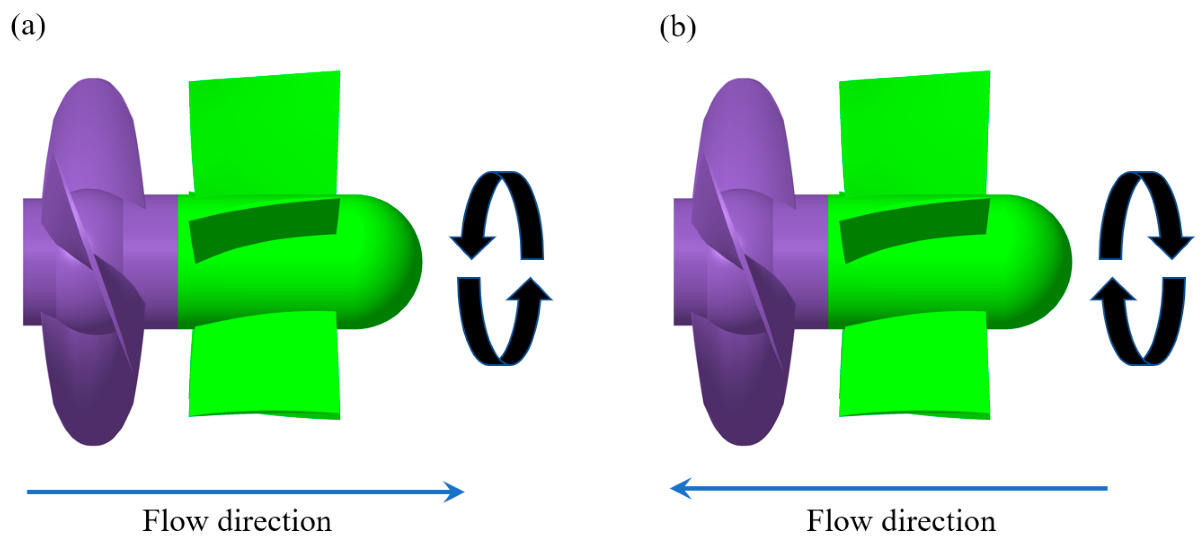
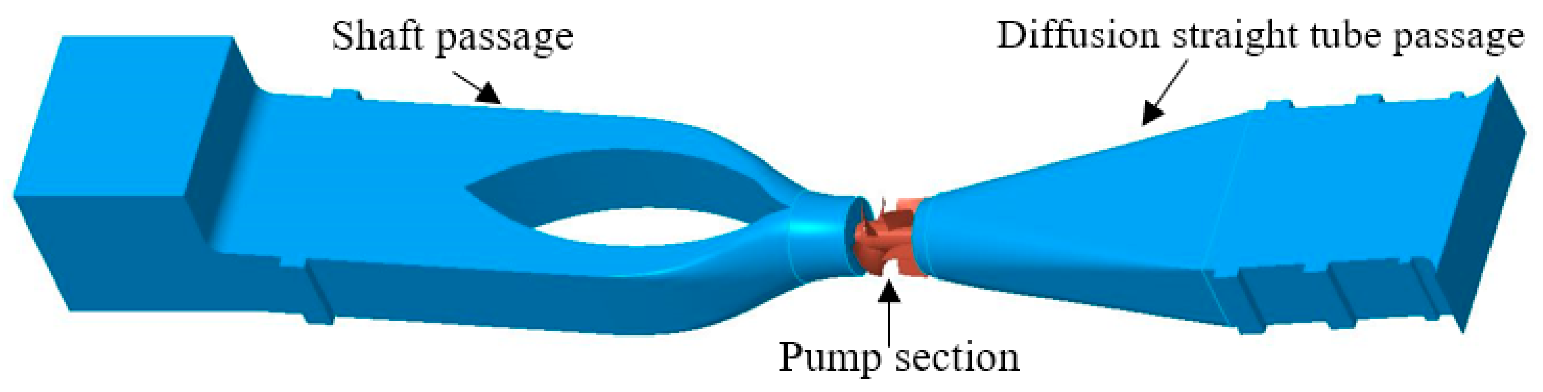
2.1. Experimental Model

The S-type bidirectional shaft tubular pump prototype model was developed by Yangzhou University, the impeller and guide vanes of which are shown in Figure 1. The pump system includes a shaft inlet passage, the pump model, and an outlet passage, which is shown in Figure 2. The impeller diameter of the pump model D is 300 mm. The rotational speed n is 1050 rpm. The number of impeller blades is 4. The blade airfoil is of symmetrical wing design, (i.e., airfoil with the same pressure surface and suction surface). The diameter of the hub of the guide vane body d is 120 mm. There are 5 guide vane blades, which are machined and welded by means of a mold. The inlet and outlet water channels are made of welded steel plates. The inner wall of the steel channel is coated to meet the roughness requirement. To facilitate the observation of the pump vane cavitation state and pump inlet state, the impeller chamber is left with several transparent observation holes.

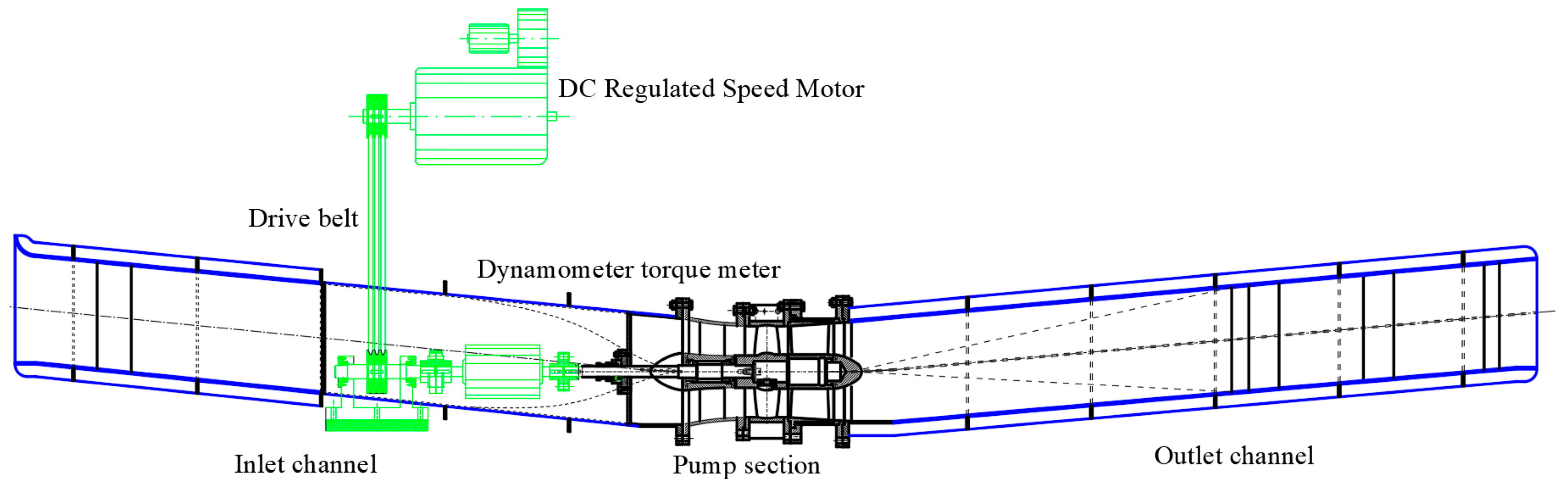
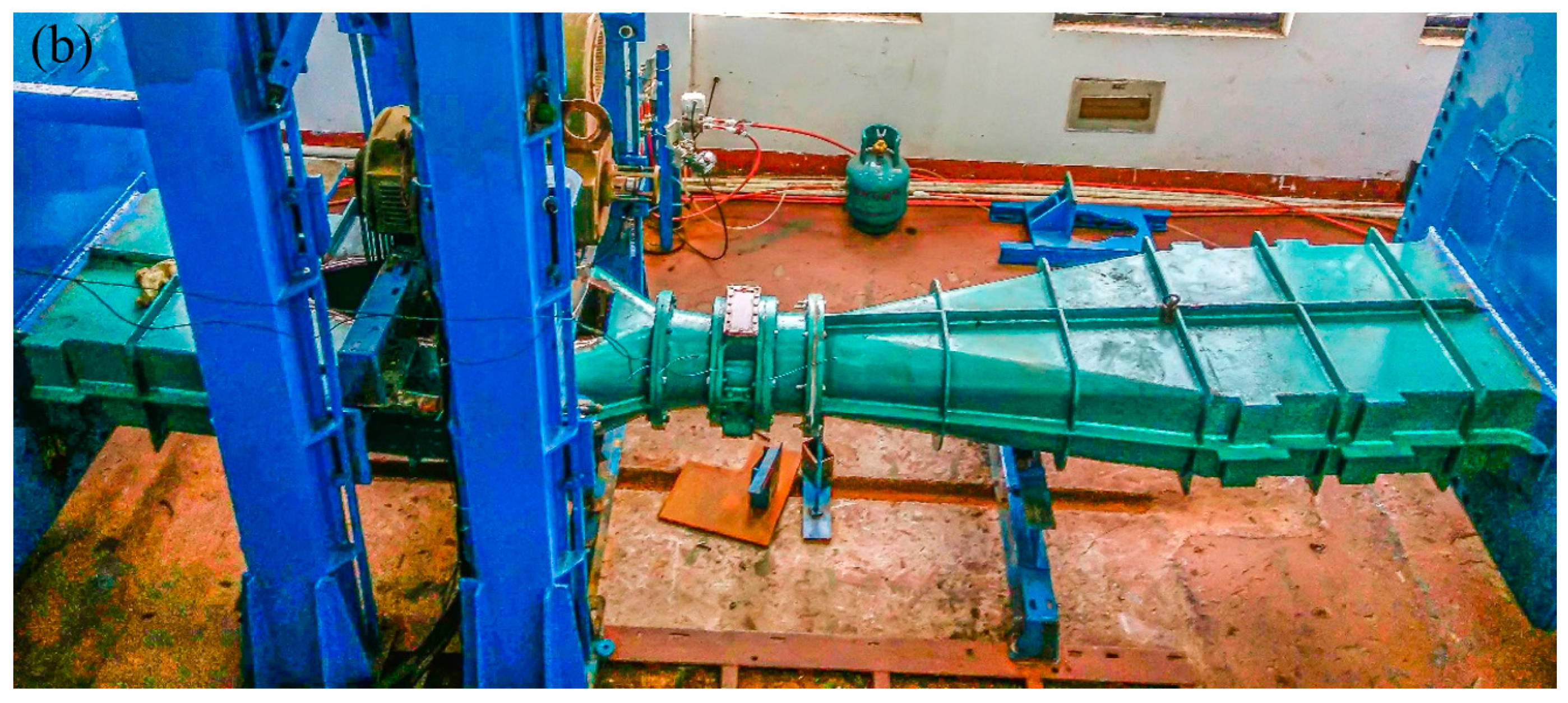
2.2. Laboratory Apparatus

The pump model was firmly installed on the test bench for the requirement of smooth operation. The test power system includes a DC motor, pulley drive mechanism, and dynamometer, which are shown in Figure 3. The torque meter and the pulley drive were installed in the shaft, and the speed-controlled DC motor transmitted power through the belt. The torque meter was installed between the pump and the pulley drive. The torque meter and the pump, the torque meter and the pulley drive were directly connected by a flexible pin coupling to ensure that the torque meter only transmitted torque.
The energy characteristics, cavitation characteristics, and runaway characteristics of the pump model at five forward and reverse blade angles (β = −4°, −2°, 0°, +2°, +4°) were tested.

2.3. Test System

The experimental tests were carried out on the high-precision hydraulic machinery test bench at Yangzhou University. The test bench is a flat closed-cycle system consisting of a hydraulic circulation system, drive motor system, control system, and measurement system, as shown in Figure 4a. The accuracy of the test system and the pump system are ±0.288% and ±0.232%, respectively, which are higher than the standard requirements.
The measurement parameters include flow rate, head, efficiency, NPSH, rotational speed, shaft power, runaway speed, and backflow. Table 1 shows all test equipment used. During the tests, all signals measured by sensors can be displayed on the instrument which is also connected to the programmable controller PLC and NI high-speed data acquisition card. The processed digital signals are transmitted to the computer, thus realizing real-time automatic data sampling and processing. The flow rate is measured by an electromagnetic flowmeter that is installed on the DN400 steel pipe and there are enough straight pipe sections in front of and behind the flowmeter to meet the measurement conditions. The speed and torque are measured by the torque-speed sensor. The head is measured by differential pressure sensors at the inlet pressure point of the vacuum tank and the outlet pressure point of the pressure tank shown in Figure 4, which can be expressed as:
H = ( z 2 z 1 + p 2 ρ g p 1 ρ g ) + ( v 2 2 2 g v 1 2 2 g )
where z 2 z 1 + p 2 / ρ g p 1 / ρ g is piezometric head measured by the differential pressure sensor, v1 and v2 are the mean flow velocity of 1-1 and 2-2 sections shown in Figure 4a.
During the cavitation tests, the rotational speed is kept constant at 1050 rpm. The vacuum pump is used to vacuum the inlet tank and gradually reduce the pressure in the closed cycle test system until cavitation occurs. Net positive suction head, (i.e., NPSH) is measured by an absolute pressure sensor at the inlet pressure measuring point of the vacuum tank. Take the working condition point at which the efficiency of the system decreases by 1% as the critical cavitation point, NPSHc can be computed by:
N P S H c = p a v ρ g + h p v ρ g
where Pav is the absolute pressure at pressure measuring point of the vacuum tank; Pv is saturated vapor pressure of water at test temperature; h is the height of pressure transmitter above the centerline of the pump runner. Shaft power P is computed by:
P = 2 π n ( M M 0 ) 60
where M is the shaft torque measured by the speed torque sensor, and M0 is no load torque of the pump shaft. The efficiency η can be calculated from the measured flow rate, head and shaft power:
η = ρ g Q H P × 100 %
In the runaway tests, the coupling between the torque instrument and the transmission device is disconnected. The bidirectional pump is to run in reverse mode by turning on the auxiliary pump shown in Figure 4a. The reverse runaway speed N u and backflow rate Q u can be calculated by the measured flow rate Q, head H, and rotary speed n:
N u = n D H
Q u = Q D 2 H

3. Experimental and Numerical Results

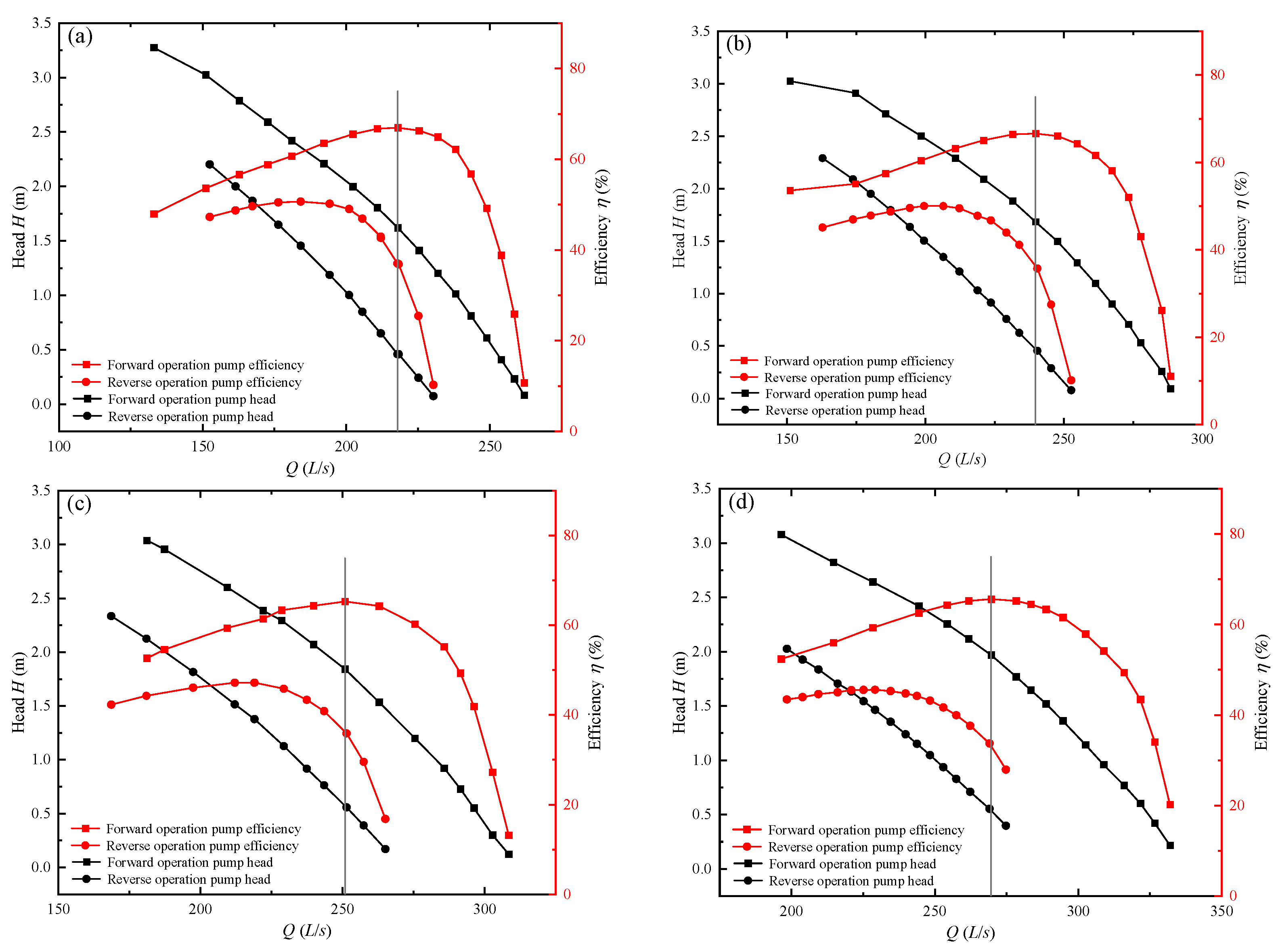
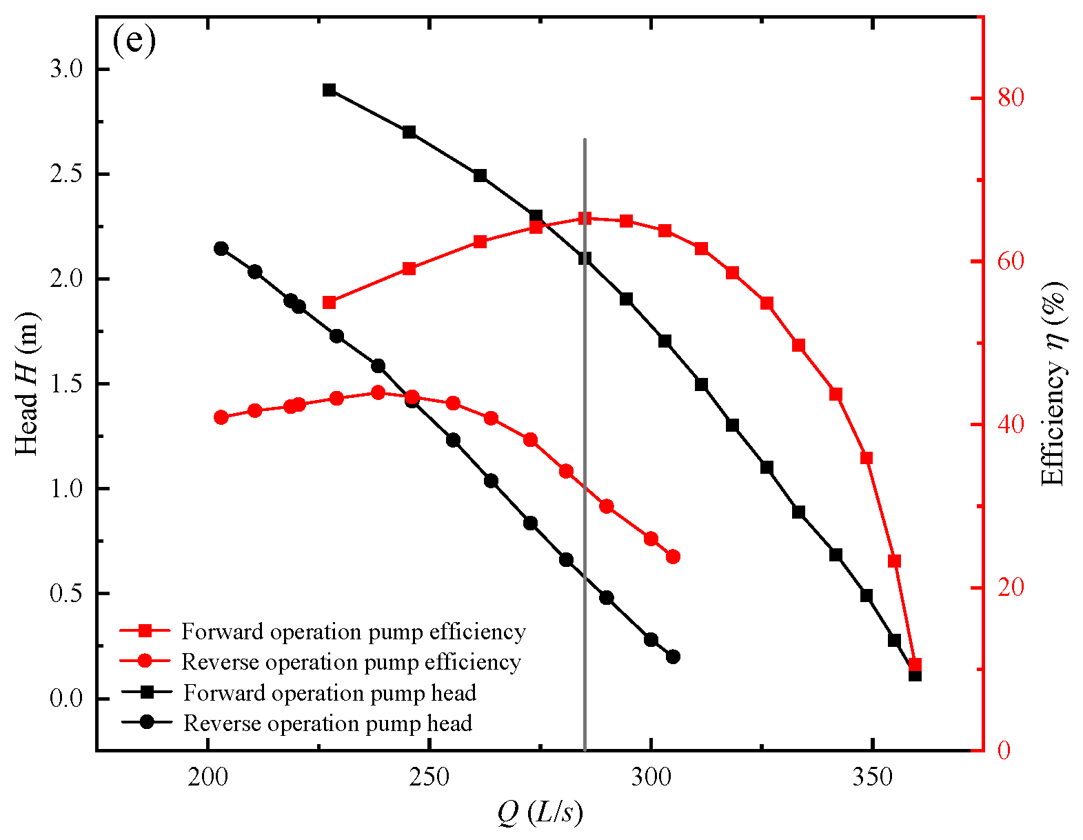
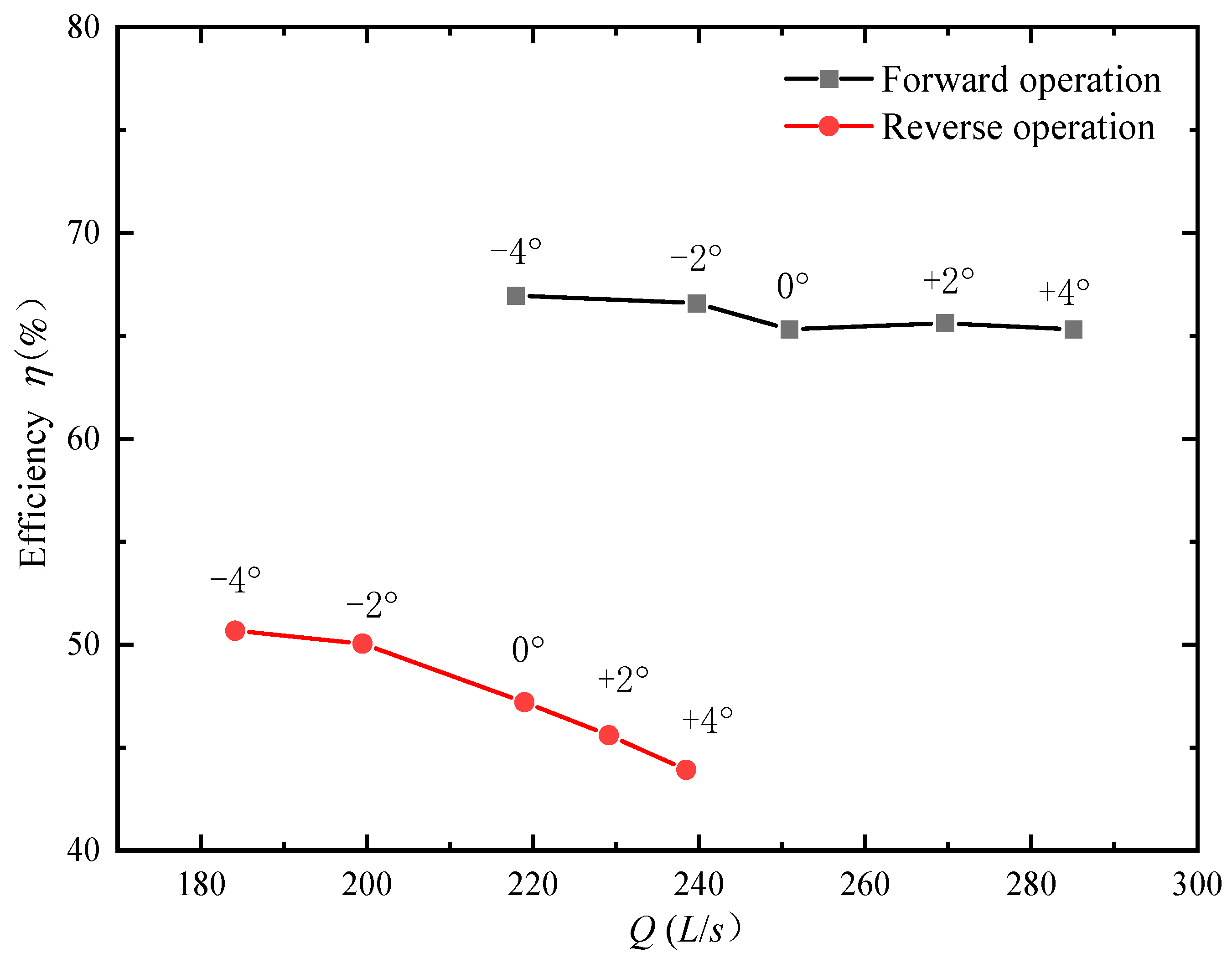
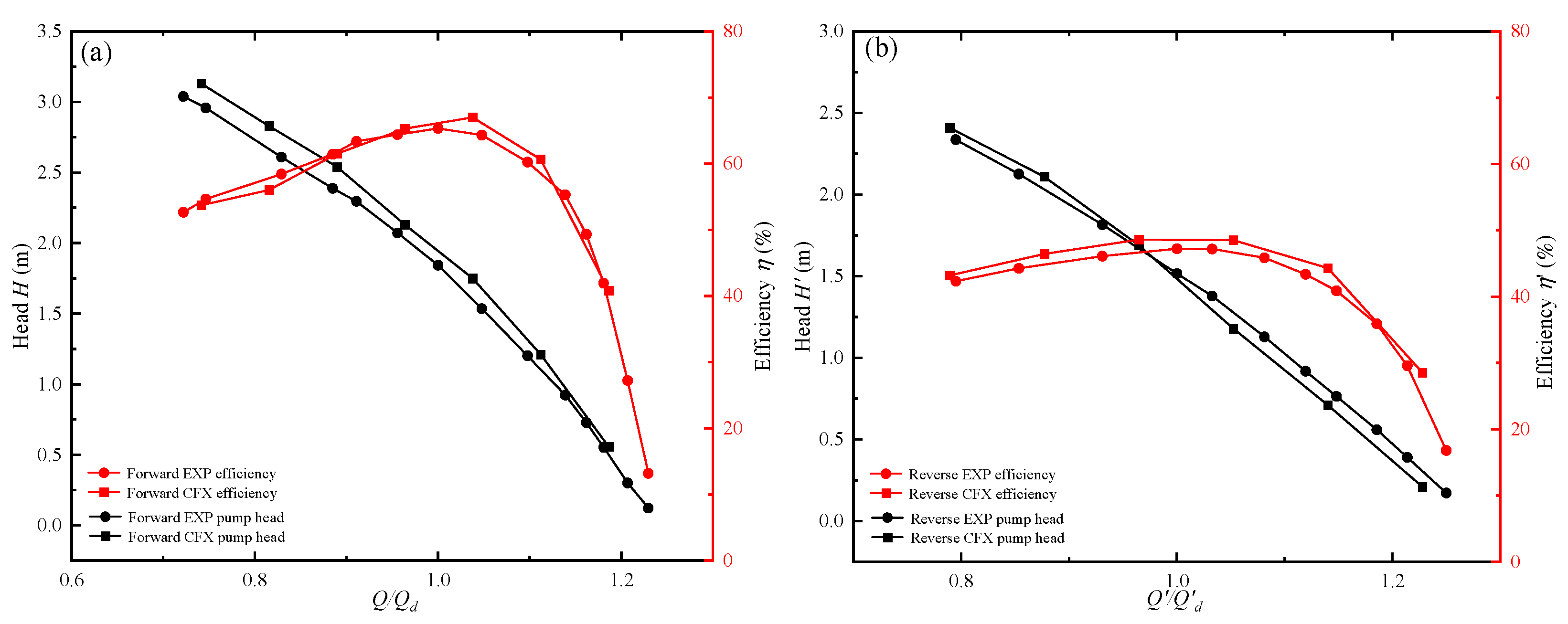
3.1. Experimental Energy Characteristics

As shown in Figure 5, the energy characteristics of the S-type bidirectional shaft tubular pump were tested at 1050 rpm at five blade angles in forward and reverse operations. At each blade angle, the variation trend of efficiency and head with a flow rate in reverse operation is similar to that in forward operation, but differs considerably in magnitude. The superscript apostrophe denotes the corresponding values in reverse operation as those in forward operation at the same blade angle and the same flow rate. It can be seen that the efficiency and head of the pump in reverse operation are much lower than those in forward operation. There exists a design flow rate Q d ( Q d for reverse operation), where an increase or decrease in flow rate results in an increase or decrease in efficiency while all other factors remain constant. The head H ( H for reverse operation) decreases gradually with the increase in flow rate.
It is noteworthy that for all blade angles, the value of H is roughly as low as 0.4 m when the reverse flow rate equals the forward operation design flow rate Q d (vertical line) shown in Figure 5. This can be explained by combining the impeller velocity triangles theory and the theoretical pump head theory expressed by the Euler equation. Firstly, a symmetric airfoil blade on the cylindrical surface with impeller radius R = 105 mm is intercepted for the inlet and outlet velocity triangles shown in Figure 6. For symmetric airfoil blade pumps at the forward operation design flow rate Q d , the absolute blade outlet flow angle α 2 is approximately equal to the guide vane inlet angle α 3 at which the direction is along the tangent direction of the guide vane inlet shown in Figure 6a. In reverse operation, the absolute inlet angle of the blade in reverse operation α 1 is determined by the reverse outlet direction angle of the guide cane α 3 , i.e., α 1 = α 3 . Due to the symmetry of the cascade, the inlet and outlet velocity triangles are the same when Q = Q d shown in Figure 6b. Therefore, the theoretical head of the pump in reverse operation H T based on the Euler equation is:
H T = u v u 2 u v u 1 ( 1 + P * ) g
where u is the circumferential velocity, v u 1 and v u 2 are the circumferential component of the absolute velocity of the blade inlet and outlet, and P* is the coefficient. Theoretically, when Q = Q d , v u 1 = v u 2 , so that H T = 0 . Equation (7) can also be expressed as Equation (8). However, there is no ideal situation in these experiments, and v u 2 is slightly larger than v u 1 , resulting in reverse operation head H being slightly larger than 0. The value obtained by experiments is about 0.4 m.
H T = u ( u Q d A cot β 2 ) u Q d A cot α 1 ( 1 + P * ) g = 0
where A = π ( D 2 d 2 ) / 4 , D is impeller diameter, and d is hub diameter. When the reverse operation flow rate Q is not equal to Q d , the theoretical head H T can express as:
H T = u ( u Q d Δ Q A cot β 2 ) u Q d Δ Q A cot α 1 ( 1 + P * ) g   and   Q = Q d Δ Q
H T = u ( cot β 2 + cot α 1 ) ( 1 + P * ) A g ( Q d Q )
According to Equation (10), it is also found that when Q is greater than Qd, the theoretical head H T is less than 0 in the ideal situation.
Under the reverse operating condition, the optimal efficiency and corresponding flow rate of the pump are always lower than those in the forward operating condition shown in Figure 7. In forward operation, the optimal efficiency for each blade angle is almost the same, i.e., about 66%. The flow rate at optimal efficiency increases monotonically with blade angle, from a minimum of 217.91 L/s at β = −4° to a maximum of 285.06 L/s at β = +4°. On the other hand, in reverse operation, the optimal efficiency decreases with blade angle, i.e., from 50.67% at β = −4° to 43.92% at β = +4°. The maximum and minimum optimal efficiencies decrease by 24.33% and 32.76%, respectively, compared to those of forward operation.

3.2. Numerical Energy Characteristics

In order to reveal the internal flow field of the bidirectional pump and find the reason for the difference in unit head and efficiency between forward and reverse operations, numerical simulations were carried out on the case of β = 0° using software CFX. The SST k ω turbulence model was chosen since it is widely used in numerical simulation of rotating machinery, (e.g., [15,16,19]). The k and ω equations of the SST k ω model are as follows:
( ρ k ) t + x j ( ρ U j k ) = x j [ ( μ + μ t σ k ) k x j ] + P k β ρ k ω + P k b
( ρ ω ) t + x j ( ρ U j ω ) = x j [ ( μ + μ t σ ω ) ω x j ] + a ω k P k β ρ ω 2 + P ω b
where ρ is the fluid density; x j is the coordinate component; U j is the velocity vector. P k is the production rate of turbulence; μ t is the turbulent viscosity. P ω b and P k b is the buoyancy production term.
The inlet boundary condition was set as pressure inlet, and the outlet boundary condition was set as mass flow outlet. The grid of fluid domain and the results of the grid independence test are shown in Figure 8a,b, respectively. It is shown that when the number of grids of the pump unit exceeds 10 million, the relative error in the calculated head is within 0.3%. Therefore, in the present study, the number of grids is set at 10 million.
The comparison between the numerical calculation results and the experimental results for blade angle β = 0° is shown in Figure 9. The design flow rates under forward and reverse operations Q d and Q d are 250.85 L/s and 212.07 L/s for blade angle β = 0°, respectively. For forward operation at the design flow condition, the efficiency and the head are 65.32% and 1.84 m, respectively. For reverse operation at the design flow condition, in comparison, the efficiency and the head are 47.21% and 1.516 m, respectively, which are considerably lower than the corresponding values for forward operation. The difference between maximum efficiency and minimum efficiency is 52.14%. In general, the simulated curves of head and efficiency are basically consistent with those obtained experimentally, indicating that the numerical simulation method is accurate and feasible. The predicted efficiency under forward and reverse operations is slightly higher than that obtained experimentally. The relative error is within 3%.
Furthermore, at the same flow rate, the pump efficiency of reverse operation is much lower than that of the forward operation. Streamlines distributions at a flow rate of 250.85 L/s for forward and reverse operations reveal the reason for this difference as shown in Figure 10. In the reverse operation, there is an obvious outlet circulation existing in the shaft passage, but in the forward operation, it is not obvious. The turbulence dissipation is the dominant loss in shaft passage for reverse operation. Figure 11 shows the hydraulic loss of the pump obtained from the numerical simulation. In reverse operation, the outlet circulation cannot be reduced as there is no guide vane at the outlet of the pump, resulting in a higher hydraulic loss compared to that of forward operation. In addition, under the small flow rate condition, the reverse outlet circulation is larger, so the hydraulic loss of shaft passage Δ H 1 increases with the decrease in flow rate. In addition, Δ H 1 is much larger than that of forward at the same flow rate as shown in Figure 11a.
For the forward operation, although the guide vane exists, there is still a certain circulation at the outlet when the flow rate is significantly small or large, (i.e., deviating from the design flow rate Q d ). This leads to a trend of decreasing first and then increasing in the hydraulic loss of the diffusion straight tube passage Δ H 2 shown in Figure 11b. On the whole, the total hydraulic loss of the passage Δ H during reverse operation is significantly greater than that in forward operation as shown in Figure 11c.
The efficiency of forward operation η and reverse operation η can be expressed as:
η = [ 1 k j ( Q d Q ) 2 + k c ( Q d Q ) 2 + k f Q 2 + Δ h H T ] η v η m
η = [ 1 - k j ( Q d Q ) 2 + k f Q 2 + Δ h H T ] η v η m
where k j and k c are the impact loss coefficient of the blade and guide vane inlet, k f is frictional hydrodynamic loss coefficient, Δ h is total hydraulic loss of flow channel, ηv is volume loss efficiency, and ηm is mechanical loss efficiency. Under the same blade angle, ideally, η v η v , η m η m , k f k f , k c k j , k j = λ / ( 2 g A 2 ) and λ = 5.5 ~ 11.0 . Therefore, the difference in total hydraulic loss between forward and reverse operations is the difference between Δ H 3 = k j ( Q d Q ) 2 + Δ h for forward operation and Δ H 3 = Δ h for reverse operation, as shown in Figure 11d. It can be found that only under very small flow conditions (<160 L/s), the hydraulic loss for reverse operation is less than that for forward operation. Therefore, the efficiency of reverse operation is greater than that of forward operation only under a small flow rate.

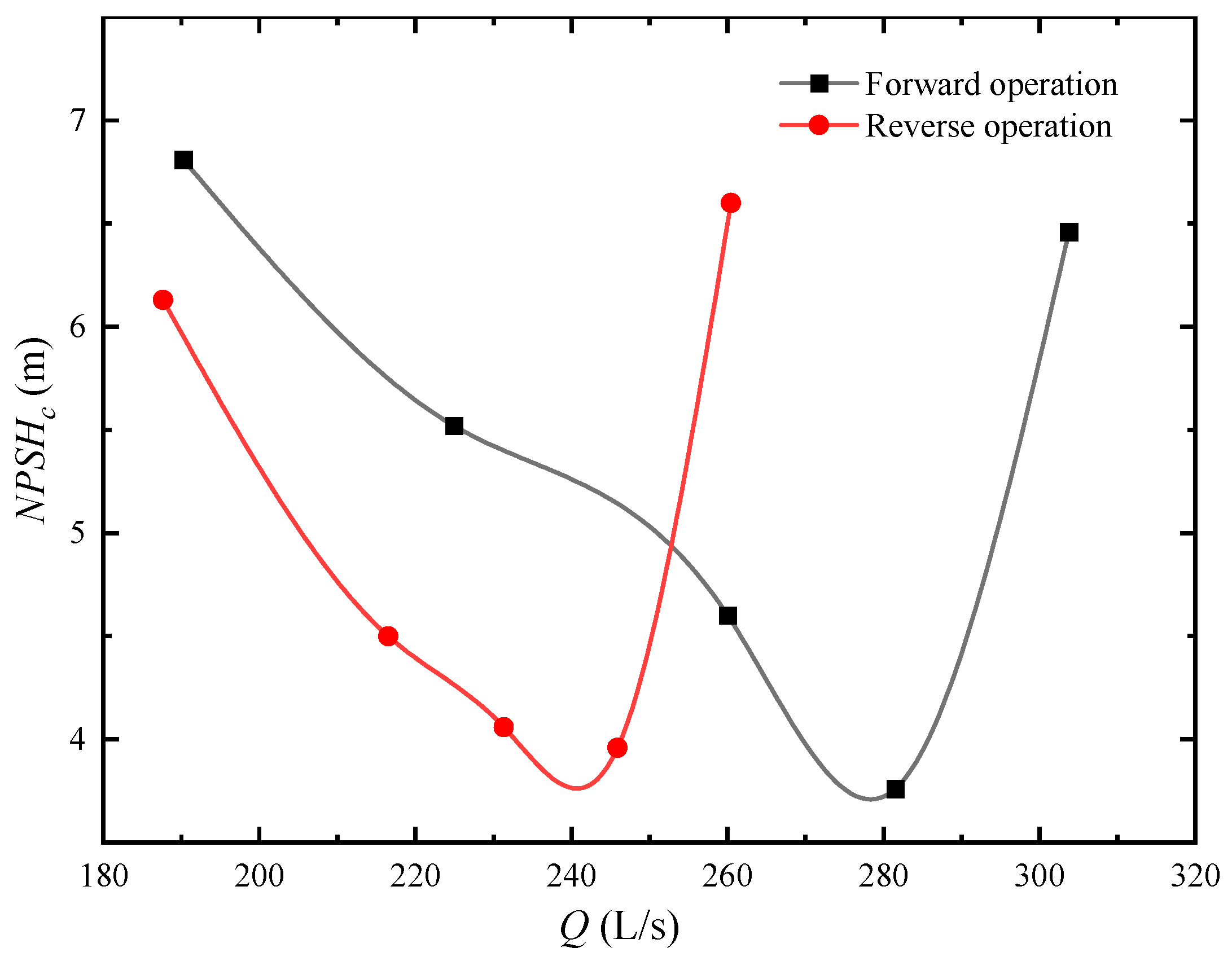
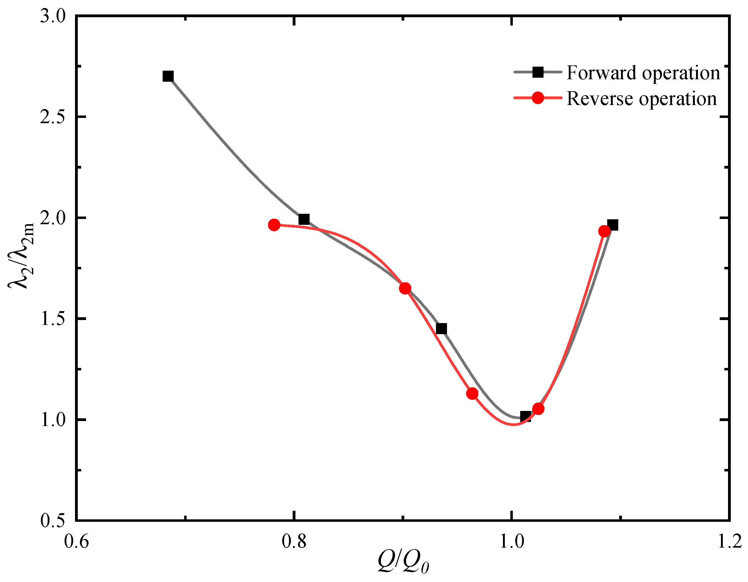
3.3. Cavitation Characteristics

The critical net positive suction head NPSHc of the pump was tested in forward and reverse operating conditions at five blade angles. The cavitation characteristics for forward and reverse operations are similar. As the flow rate increases, the value of NPSHc tends to decrease first and then increase, as shown in Figure 12; in other words, for each angle, NPSHc attains a minimum value. For forward operation, NPSHc for β = −4° is the smallest at Q/Qd < 1.06 and is the largest at Q/Qd > 1.14. Take the case of β = 0° as an example. For forward operation, NPSHc achieves a minimum of 3.76 m and a maximum of 6.81 m at Q = 281.5 L/s and 190.24 L/s, respectively. In comparison, for reverse operation, NPSHc attains a minimum of 3.96 m and a maximum of 6.6 m at Q = 245.9 L/s and 26.45 L/s, respectively. The N P S H c Q curve for reverse operation at β = 0° can be regarded as a parallel shift to the left of the forward operation curve shown in Figure 13. It can be found that the trend of NPSHc with flow rate is the same under forward and reverse operations. The values of minimum NPSHc and maximum NPSHc for the two operating conditions (forward and reverse) are basically the same.
Furthermore, in order to theoretically analyze the cavitation characteristics, NPSHc can be calculated by:
N P S H c = λ 1 v 1 2 2 g + λ 2 w 1 2 2 g
where λ 1 and λ 2 are dynamic pressure-drop coefficients, λ 1 = 1–1.1, and λ 2 varies greatly with different working conditions. The value of λ 2 is a symbol of the cavitation characteristics of the pump. In this paper, combined with velocity triangles for the symmetric airfoil blade at the inlet and outlet shown in Figure 6 and Equation (15), the forward and reverse dynamic pressure-drop coefficients λ 2 and λ 2 can be expressed as:
λ 2 = ( 2 g N P S H a v λ 1 Q 2 A 2 ) / [ ( π n 30 R ) 2 + Q 2 A 2 ]
λ 2 = ( 2 g N P S H a v λ 1 Q 2 A 2 sin 2 α 3 ) / [ ( π n 30 R Q A cot α 3 ) 2 + Q 2 A 2 ]
where λ 1 = 1.05. The experimentally obtained minimum NPSHc at the five blade angles in forward and reverse operations are, respectively, substituted into Equation (16) and Equation (17) to calculate the values of λ 2 and λ 2 , which are shown in Table 2. For forward operation, λ 2 attains the smallest value of 0.322 at β = 0° and increases with the increase in deviation from for β = 0°. However, for reverse operation, λ 2 increases with the increase in β with a minimum of 0.218 and a maximum of 0.419.
The dimensionless quantity λ 2 / λ 2 m ( λ 2 / λ 2 m for reverse operation) was introduced to compare the cavitation performance under different flow rates, where λ 2 m is the value of λ 2 corresponding to the minimum NPSHc at each specific blade angle. Comparison between forward and reverse operations for blade angle β = 0° is shown in Figure 14, where Q 0 is the flow rate at the minimum NPSHc. It can be observed that the two curves nearly coincide; therefore, cavitation performance of the pump in forward and reverse operations is almost the same.

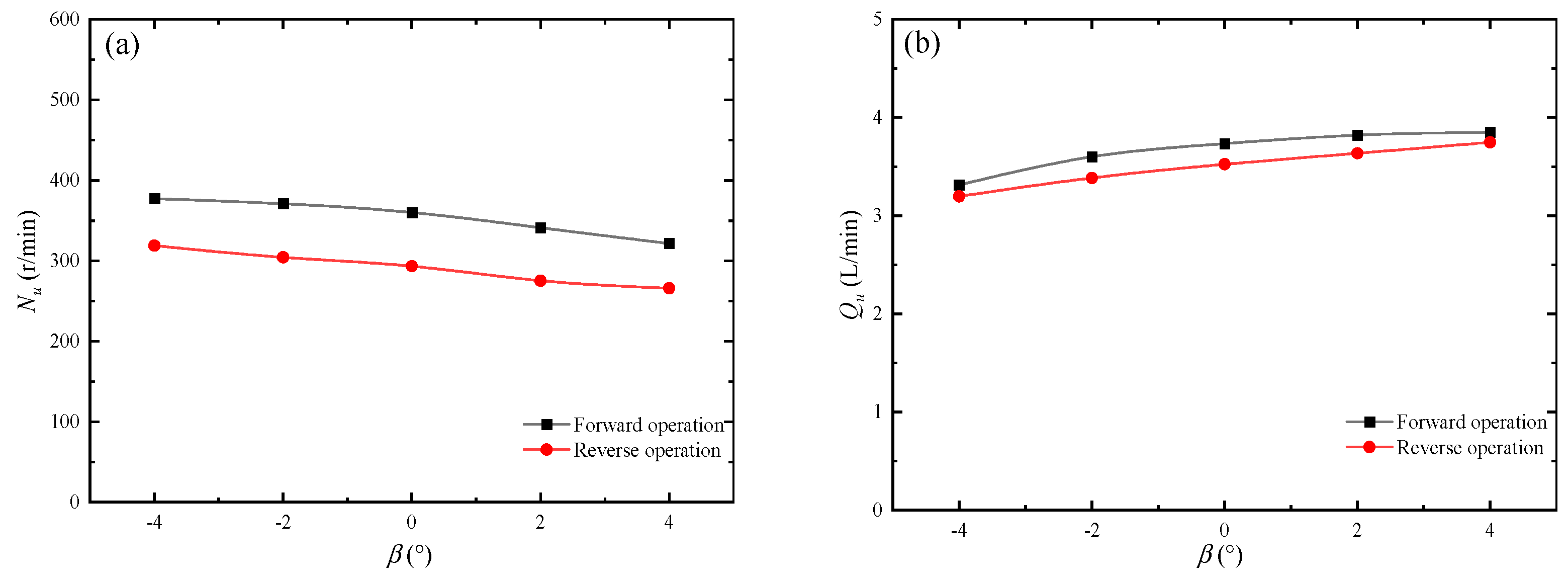
3.4. Runaway Characteristics

The unit runaway speed Nu and unit backflow rate Qu at different blade angles for forward and reverse operations are shown in Figure 15. The values of Nu and Qu of forward operation are greater than those of reverse operation Nu′ and Qu′. The difference in runaway speed between forward and reverse operations at each angle is all about 50 rpm, which is reflected by the two almost parallel lines in Figure 15a. In comparison, the difference in flow rate is relatively small as shown in Figure 15b.
In this paper, we considered combining the theory of the velocity triangles at the inlet and outlet shown in Figure 16, and rotational speed calculation for Equation (5) to predict the runaway speed in forward and reverse operations Nu and Nu′. Similarly, the backflow rates Qu and Qu′ can also be predicted by combining the theory of the velocity triangles for the blade at the inlet and outlet, and Equation (6) for the flow rate calculation.
Theoretically, the pump has no energy input and output in a runaway state. Therefore, the absolute speed at the inlet and outlet of the blade shall be equal to the partial speed on the circumference, i.e., v u 2 = v u 1 for forward operation, v u 2 = v u 1 = 0 for reverse operation. According to the blade velocity triangles at the inlet and outlet shown in Figure 15, we can obtain:
v u 1 = v m cot α ,   v u 2 = u v m cot β 2 ,   v m cot α = u v m cot β 2
u v m cot β 2 = 0
where u and u are the circumferential velocities in forward and reverse runaway states, respectively. From the velocity triangles, it is known that α 1 = α 3 , β 2 = β 2 . The forward runaway speed Nu and reverse runaway speed Nu′ can be expressed as:
N u = 60 π D Q A ( cot α 3 + cot β 2 )
N u = 60 π D Q A cot β 2
Considering forward head H = s 1 Q 2 and reverse head H = s 2 Q 2 in runaway state and combined with Equations (5), (6), (20) and (21), Nu, Nu′, Qu, and Qu′ can be expressed as:
N u = η [ 60 π A ( cot α 3 + cot β 2 ) ] / s 1
N u = η ( 60 π A cot β 2 ) / s 2
Q u = 1 D 2 s 1
Q u = 1 D 2 s 2
where σ is the correction coefficient. In the Eulerian velocity triangle, it is assumed that the blades are infinitely many and infinitely thin, and the relative flow velocity at any point is along the tangential direction of the blades. Ideally, the correction factor σ = 1. In this experiment, a correction factor σ = 1.36 is obtained according to the measurement results. The resistance coefficients s 1 and s 2 can be calculated from the measured head and the backflow rate in forward and reverse runaway states. The values of β 2 and α 3 are the corresponding blade outlet angle and guide vane inlet angle of the middle section of the symmetrical blade of R = 105 mm. The values of s 1 , s 2 , β 2 and α 3 are shown in Table 3. In Figure 17a with a 5% variation interval included, we compare the measured data with Equation (22) for the forward runaway speed Nu and Equation (23) for the reverse runaway speed Nu′. The calculated data by Equation (24) for Qu and Equation (25) for Qu′ are also compared with the measured data shown in Figure 17b. The calculated data shows a good agreement with the experimental measurements, which proves that Equations (22)–(25) can well predict the runaway characteristics in both forward and reverse operations.

4. Conclusions

The present study was conducted to analyze the difference between the forward and reverse operating conditions of an S-shape bidirectional shaft tubular pump. The energy characteristics, cavitation characteristics, and runaway characteristics of the pump at five blade angles (β = −4°, −2°, 0°, +2°, +4°) were tested. Numerical simulations for the case of blade angle β = 0° were also used to reveal the internal flow field. The following conclusions can be drawn:
At the same blade angle and flow rate, the head of the pump in reverse operation is lower than that in forward operation. In reverse operation, the head of the pump H is nearly 0 m at the design flow rate Q d . It can be explained by combining the impeller velocity triangle theory and the theoretical pump head theory expressed by the Euler equation. The efficiency calculation formulas for forward and reverse operations are also summarized. The reason for the difference in efficiency between forward and reverse operations was explored by numerical simulation. The hydraulic losses at different sections of the pump are obtained. It is found that the efficiency of the pump in reverse operation is greater than that in forward operation only under particularly small flow rate.
The cavitation characteristics of the pump in forward and reverse operations are similar. The NPSHc curve at each blade angle has the same trend and is parallel to each other. As the flow rate increases, NPSHc tends to decrease and then increase, i.e., having a minimum value. The dynamic pressure-drop coefficients in forward and reverse operations, λ 2 and λ 2 , are obtained. A dimensionless parameter λ 2 / λ 2 m ( λ 2 / λ 2 m for reverse operation) was introduced to compare the cavitation performance of the pump under different flow rates. It is found that the cavitation performance of the S-type bidirectional shaft tubular pump under forward and reverse operations is almost the same.
The rotational speed N u and backflow rate Q u of the pump in forward operation are greater than those in reverse operation N u and Q u . Moreover, four equations have been developed to predict N u , Q u , N u and Q u , respectively. The predictions show good agreement with the experimental data.

Author Contributions

Conceptualization, J.C. and H.S.; methodology, J.M.; software, J.C.; validation, J.C.; formal analysis, J.C.; investigation, J.M.; resources, X.W.; writing—original draft preparation, J.C.; writing—review and editing, X.W. All authors have read and agreed to the published version of the manuscript.

Funding

This research work was supported by the National Natural Science Foundation of China (funder: National Natural Science Foundation of China. funding number: 52079057), and the National Natural Science Foundation of China (funder: National Natural Science Foundation of China. funding number: 52106043).

Institutional Review Board Statement

Not applicable.

Informed Consent Statement

Not applicable.

Data Availability Statement

Not applicable.

Conflicts of Interest

The authors declare no conflict of interest.

References

  1. Bozorgi, A.; Javidpour, E.; Riasi, A.; Nourbakhsh, A. Numerical and experimental study of using axial pump as turbine in Pico hydropower plants. Renew. Energy 2012, 53, 258–264. [Google Scholar] [CrossRef]
  2. Fu, S.; Zheng, Y.; Kan, K.; Chen, H.; Han, X.; Liang, X.; Liu, H.; Tian, X. Numerical simulation and experimental study of transient characteristics in an axial flow pump during start-up. Renew. Energy 2020, 146, 1879–1887. [Google Scholar] [CrossRef]
  3. Shi, L.; Zhu, J.; Tang, F.; Wang, C. Multi-Disciplinary Optimization Design of Axial-Flow Pump Impellers Based on the Approximation Model. Energies 2020, 13, 779. [Google Scholar] [CrossRef] [Green Version]
  4. Zhang, D.; Shi, W.; Bin, C.; Guan, X. Unsteady Flow Analysis and Experimental Investigation of Axial-Flow Pump. J. Hydrodyn. 2010, 22, 35–43. [Google Scholar] [CrossRef]
  5. Kan, K.; Zheng, Y.; Chen, H.; Zhou, D.; Dai, J.; Binama, M.; Yu, A. Numerical simulation of transient flow in a shaft extension tubular pump unit during runaway process caused by power failure. Renew. Energy 2020, 154, 1153–1164. [Google Scholar] [CrossRef]
  6. Shi, L.; Yuan, Y.; Jiao, H.; Tang, F.; Cheng, L.; Yang, F.; Jin, Y.; Zhu, J. Numerical investigation and experiment on pressure pulsation characteristics in a full tubular pump. Renew. Energy 2020, 163, 987–1000. [Google Scholar] [CrossRef]
  7. Zhao, W.; Zhang, J.; Yu, X.; Zhou, D.; Calamak, M. Multiobjective optimization of a tubular pump to improve the applicable operating head and hydraulic performance. Proc. Inst. Mech. Eng. Part C J. Mech. Eng. Sci. 2020, 235, 1555–1566. [Google Scholar] [CrossRef]
  8. Cheng, K.; Li, S.; Cheng, L.; Sun, T.; Zhang, B.; Jiao, W. Experiment on Influence of Blade Angle on Hydraulic Characteristics of the Shaft Tubular Pumping Device. Processes 2022, 10, 590. [Google Scholar] [CrossRef]
  9. Kan, K.; Zheng, Y.; Fu, S.; Liu, H.; Yang, C.; Zhang, X. Dynamic stress of impeller blade of shaft extension tubular pump device based on bidirectional fluid-structure interaction. J. Mech. Sci. Technol. 2017, 31, 1561–1568. [Google Scholar] [CrossRef]
  10. Li, C.; Zheng, Y.; Zhang, Y.; Kan, K.; Xue, X.; Fernandez-Rodriguez, E. Stability Optimization and Analysis of a Bidirectional Shaft Extension Pump. J. Fluids Eng. 2020, 142, 071203. Available online: https://asmedigitalcollection.asme.org/fluidsengineering/article-abstract/142/7/071203/1074627/Stability-Optimization-and-Analysis-of-a (accessed on 20 April 2022). [CrossRef]
  11. Ma, P.; Wang, J.; Li, H. Numerical Analysis of Pressure Pulsation for a Bidirectional Pump under Positive and Reverse Operation. Adv. Mech. Eng. 2014, 6, 730280. [Google Scholar] [CrossRef] [Green Version]
  12. Pei, J.; Meng, F.; Li, Y.; Yuan, S.; Chen, J. Fluid–structure coupling analysis of deformation and stress in impeller of an axial-flow pump with two-way passage. Adv. Mech. Eng. 2016, 8, 168. [Google Scholar] [CrossRef] [Green Version]
  13. Zhu, J.; Zeng, F. Experimental study on two-way flow passages in pumping system. J. Mech. Sci. Technol. 2008, 22, 1966–1970. [Google Scholar] [CrossRef]
  14. Pei, J.; Meng, F.; Li, Y.; Yuan, S.; Chen, J. Effects of distance between impeller and guide vane on losses in a low head pump by entropy production analysis. Adv. Mech. Eng. 2016, 8, 168. [Google Scholar] [CrossRef] [Green Version]
  15. Kan, K.; Zhang, Q.; Xu, Z.; Chen, H.; Zheng, Y.; Zhou, D.; Binama, M. Study on a horizontal axial flow pump during runaway process with bidirectional operating conditions. Sci. Rep. 2021, 11, 1–21. [Google Scholar] [CrossRef]
  16. Kang, C.; Mao, N.; Pan, C.; Zhou, Y. Turbulent Flow Characteristics in an Axial-flow Pump at Direct and Reverse Modes. J. Appl. Sci. Eng. 2016, 19, 447–458. [Google Scholar] [CrossRef]
  17. Ma, P.; Wang, J. An analysis on the flow characteristics of bi-directional axial-flow pump under reverse operation. Proc. Inst. Mech. Eng. Part A J. Power Energy 2017, 231, 239–249. [Google Scholar] [CrossRef]
  18. Ma, P.; Wang, J.; Wang, H. Investigation of performances and flow characteristics of two bi-directional pumps with different airfoil blades. Sci. China Technol. Sci. 2018, 61, 1588–1599. [Google Scholar] [CrossRef]
  19. Meng, F.; Li, Y.; Yuan, S.; Wang, W.; Zheng, Y.; Osman, M.K. Multiobjective Combination Optimization of an Impeller and Diffuser in a Reversible Axial-Flow Pump Based on a Two-Layer Artificial Neural Network. Processes 2020, 8, 309. [Google Scholar] [CrossRef] [Green Version]
  20. Zhang, X.; Tang, F.; Chen, Y.; Huang, C.; Chen, Y.; Wang, L.; Shi, L. Experimental Study on the Internal Pressure Pulsation Characteristics of a Bidirectional Axial Flow Pump Operating in Forward and Reverse Directions. Machines 2022, 10, 167. [Google Scholar] [CrossRef]
  21. Yang, F.; Chang, P.; Li, C.; Shen, Q.; Qian, J.; Li, J. Numerical analysis of pressure pulsation in vertical submersible axial flow pump device under bidirectional operation. AIP Adv. 2022, 12, 025107. [Google Scholar] [CrossRef]
Figure 1. Impeller and guide vanes: (a) forward operation and (b) reverse operation.
Jmse 10 00671 g001
Figure 2. Bidirectional shaft tubular pump system.
Jmse 10 00671 g002
Figure 3. Test drive motor system.
Jmse 10 00671 g003
Figure 4. Experimental setup: (a) schematic diagram of the test bench and (b) photo of the tested pump system.
Jmse 10 00671 g004aJmse 10 00671 g004b
Figure 5. Energy characteristics of the pump for blade angle β = (a) −4°; (b) −2°; (c) 0°; (d) +2°; (e) +4°. Vertical line stands for Q = Q d .
Jmse 10 00671 g005aJmse 10 00671 g005b
Figure 6. Velocity triangles for the symmetric airfoil blade at inlet and outlet for: (a) forward operation at Q = Qd; (b) reverse operation at Q′ = Qd; (c) reverse operation at Q′ < Qd; (d) reverse operation at Q′ > Qd.
Jmse 10 00671 g006
Figure 7. Optimal efficiency and corresponding flow rate at five blade angles under forward and reverse operating conditions.
Jmse 10 00671 g007
Figure 8. Mesh of CFD model: (a) grid of fluid domain and (b) mesh independence tests.
Jmse 10 00671 g008
Figure 9. Comparison between numerical and experimental results of the pump for blade angle β = 0° in: (a) forward operation; (b) reverse operation.
Jmse 10 00671 g009
Figure 10. Streamline distributions at flow rate Q = 250.85 L/s in: (a) forward operation; (b) reverse operation.
Jmse 10 00671 g010
Figure 11. Hydraulic loss of the pump in: (a) shaft passage section; (b) diffusion straight tube passage; (c) entire passage; (d) sum of entire passage and inlet impact loss.
Jmse 10 00671 g011
Figure 12. Cavitation characteristic NPSHcQ/Qd curve of the pump in: (a) forward operation; (b) reverse operation.
Jmse 10 00671 g012
Figure 13. Cavitation characteristic N P S H c Q curve of the pump at blade angle β = 0°.
Jmse 10 00671 g013
Figure 14. Variation of the λ 2 / λ 2 m ( λ 2 / λ 2 m for reverse) with Q / Q 0 ( Q / Q 0 for reverse) for blade angle β = 0°.
Jmse 10 00671 g014
Figure 15. Runaway characteristics of the pump in forward and reverse operations: (a) runaway speed; (b) backflow rate.
Jmse 10 00671 g015
Figure 16. Velocity triangles for runaway state in: (a) forward operation; (b) reverse operation.
Jmse 10 00671 g016
Figure 17. Comparison between measured and calculated: (a) unit runaway speed (b) unit backflow rate of the pump in forward and reverse operations.
Jmse 10 00671 g017
Table 1. Test equipment and related parameters.
Measuring QuantityInstrumentInstrument TypeMeasurement RangeCalibration Accuracy
HeadDifference pressure transmitterEJA110A0~250 kPa
0~100 kPa
±0.076%
absolute pressure sensorEJA1301~100 kPa±0.065%
Standard resistanceRX70-0.25250 Ω±0.01%
Digital multimeter7150 ±0.002%
Flow RateElectromagnetic flowmeterE-magDN400 mm±0.2%
TorqueSpeed torque sensorJC1A200 Nm±0.2%
Speed torque sensor indicatorTS-800B ±0.01%
Dynamic pressure sensorCYG505−0.1 Mpa–0.15 Mpa±0.2%
Table 2. Calculation results of λ 2 and λ 2 with minimum NPSHc for 5 blade angles.
Blade Angles
β (°)
Forward Operation
NPSHc (m)
Forward Dynamic Pressure-Drop Coefficient
λ2
Reverse Operation
NPSHc (m)
Reverse Dynamic Pressure-Drop Coefficient
λ2
−4°3.020.3743.620.218
−2°3.360.3403.650.236
3.760.3223.680.258
+2°5.220.3884.520.398
+4°5.620.4595.350.419
Table 3. Runaway characteristic parameters.
Blade Angles
β (°)
Resistance Coefficient
s1 (m−5s2)
Resistance Coefficient
s2 (m−5s2)
Blade Outlet Angle
β2 (°)
Guide Vane Inlet Angle
α3 (°)
−4°11.2311.882174.2
−2°9.5110.702374.2
8.859.982574.2
+2°8.459.332774.2
+4°8.38.792974.2
Publisher’s Note: MDPI stays neutral with regard to jurisdictional claims in published maps and institutional affiliations.

