Abstract
The classical theory of centralized dynamic characteristics with eight coefficients is adopted for traditional journal bearings. However, under cantilevered load, distributed dynamic characteristics along the axial direction will be generated for the journal bearing with a large aspect ratio (L/D). A double-section loading method simulating shaft bending and excitation was developed, a dynamic characteristic test-rig of a large-aspect-ratio bearing was set-up, the novel four-time vertical excitation method and eight-time cross excitation method were put forward, and the equations of 16 dynamic characteristic coefficients of the bearing were deduced. The dynamic characteristic test was carried out. The results showed that the four-time vertical excitation method had a small response amplitude in the horizontal direction, and was vulnerable to interference by the vibration of the test-rig. The eight-time cross excitation method had a higher SNR with more accurate identification results. When the cantilevered load was not applied, the dynamic characteristic coefficients were evenly distributed along the axial direction, the stiffness coefficients fluctuated slightly as the rotation rate increased, while the main damping coefficients decreased significantly. Shaft bending resulted in a significant increase in local dynamic characteristic coefficients, in which the relative increase in the stiffness coefficients was greater than that of the damping coefficients. Increasing the rotational speed can weaken the effect of shaft bending, and key factors that cause the axially nonuniform distribution of dynamic characteristic coefficients of the bearing are shaft bending and large aspect ratio under low speed and cantilevered load.
1. Introduction
The evolution and control mechanisms of vibration and noise of marine propulsion shafting are hot topics in the field of rotor dynamics [1,2,3]. The propulsion shafting transmits the engine power and propeller thrust in the power system, in which the stern bearings support the propeller shaft. As a key component of the vibration energy transfer link of the propeller-shafting-engine-hull, the dynamic characteristics of stern bearings affect the dynamic behavior of the propulsion shafting and is critical to the operation quality of the propulsion system [4,5]. Accurate identification of dynamic characteristic coefficients of the stern bearing is of great value to reveal the dynamic behaviors of the propulsion shafting and to put forward a vibration and noise reduction method, and is also of great significance to realize the fault diagnosis of vibration of the marine engine room.
The structure and working conditions of stern bearings are different from those of common journal bearings. The aspect ratio (the ratio of length to diameter of a bearing) of common journal bearings is 0.8~1.2, while that of stern bearings is as high as 2~4 [6]. In addition, a common journal bearing generally receives the load in the middle. However, under the action of propeller gravity, the stern bearing receives a cantilevered load, and as the tonnage increases, the propeller becomes larger, resulting in serious bending of the propeller shaft under cantilevered load [7]. As shown in Figure 1, a centralized dynamic model is generally adopted for common bearings with a middle load. It is assumed that the bearing has an equivalent fulcrum supporting the rotating shaft, and there are eight dynamic characteristic coefficients (four stiffness coefficients and four damping coefficients) on the section passing through the fulcrum and perpendicular to the axis [8]. However, this centralized dynamic model is not applicable to the stern bearing, as a large aspect ratio and shaft bending under the cantilevered load lead to serious uneven distributions in the thickness and pressure of the liquid film along the axial direction of the stern bearing [9], and the extrusion and shear effects in axial areas of the bearing interface differ greatly, which makes it difficult to find the above “equivalent fulcrum”. The dynamic characteristics of the bearing are distributed, which warrants a theory on distributed dynamic characteristics to be established [10].
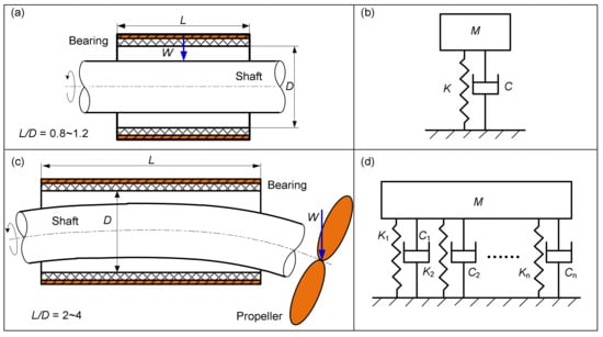
Figure 1.
Two kinds of structure and dynamic models of journal bearings: (a) structure of common journal bearing; (b) dynamic model of common journal bearing; (c) structure of large-aspect-ratio journal bearing; (d) dynamic model of large-aspect-ratio journal bearing.
A variety of methods for the identification of dynamic characteristic coefficients of journal bearings have been reported [11], which can be divided into the external excitation method and the self-excitation method by the source of excitation. The external excitation method refers to artificial excitation being applied on the shaft or bearing. The test-rig that applies the excitation on the shaft is called the positive test-rig [12], and that which applies the excitation on the bearing is called the inverted test-rig [13]. The external excitation method includes the stable excitation method [14] and the transient excitation method, and the former method includes the single-frequency twice excitation method, the compound excitation method, and the multi-frequency excitation method. Reddy et al. [15] identified the dynamic characteristic coefficients of a tilting-pad bearing by the single-frequency twice excitation method, and the difference between the measured value and the simulation value calculated based on the TEHD model was about 10%. Ciulli et al. [16] identified the dynamic characteristic coefficients of a tilting-pad journal bearing by using the compound excitation method, analyzed the deformed orbits of the rotor under different dynamic loads, and studied the nonlinearity of the oil-film force under large excitation. The transient excitation method includes the wide-band excitation method and the pulse excitation method. Jiang et al. [12] identified the dynamic characteristic coefficients of a journal bearing with a diameter larger than 500 mm by using the pulse excitation method. Matta et al. [17] identified the dynamic characteristic coefficients of a journal bearing by using the hammering method and studied the frequency dependence of the linear dynamic coefficients. The multi-frequency excitation method is an ideal method as it has the advantages of high response energy concentration and high SNR of the stable excitation method, as well as the wide frequency range of the transient excitation method. Chatterton et al. [18] studied the relationship between the excitation frequency and dynamic characteristic coefficients of a tilting-pad bearing by using this method.
The external excitation is not required for the self-excitation method. Generally, the unbalanced force of the rotor is used to excite the bearing, but the ill-conditioned matrix problem may occur in the identification of dynamic characteristic coefficients [19]. Tiwari et al. [20], by collecting the acceleration signals in the horizontal and vertical directions of the bearing pedestal, identified the dynamic characteristic coefficients of the bearing by using the synchronous unbalanced response components and singular value decomposition method on the frequency domain graph of the acceleration signals. Zhang et al. [21] identified the dynamic characteristic coefficients of large-size journal bearings in a 300 MW turbo generator by using the unbalanced excitation method. Mao et al. [22] transformed the identification of dynamic characteristic coefficients of the bearing into an inverse problem and reversed the dynamic characteristic coefficients of the bearing by minimizing the difference between the simulation value and the measured value of the unbalanced response of a rotor-bearing system.
The above methods mainly focus on the centralized dynamic characteristics of bearings, and the main purpose is to obtain the dynamic characteristic coefficients of the whole bearing to solve the bearing dynamic model. However, it is difficult for this dynamic characteristic coefficient to comprehensively reflect the dynamic characteristics for large-aspect-ratio journal bearings under the condition of shaft bending. In terms of theories of the dynamic characteristics of large-aspect-ratio journal bearings, Liu et al. [23,24], taking a flexible multi-stage rotor-bearing as the object, innovatively built the multi-point supporting model of water-lubricated rubber bearings and the dynamical model of the rotor system, and analyzed the optimal placement of the rubber bearings, the critical rotational speed, and the steady-state response. However, there are very few studies on the test method for the distributed dynamic characteristics of large-aspect-ratio journal bearings. In Ref. [25], a method for identifying the dynamic characteristic coefficients at both ends of the bearing was proposed for the first time, but the dynamic model was simplified, and only the main stiffness and damping coefficients in the vertical direction of the bearing were identified. In general, the identification method of dynamic characteristic coefficients for large-aspect-ratio bearings is still lacking. Especially under the condition of shaft bending, the dynamic coefficients of different fulcrums have significant differences that need to obtain the more dynamic characteristic coefficients to reflect the bearing dynamic performance.
For this cause, in this paper, a bearing dynamic characteristic test-rig that can simulate shaft bending was established. A novel identification method of dynamic characteristics of the bearing was put forward to solve the 16 dynamic characteristic coefficients of the multi-point supporting model. The identification experiment was carried out, and the effect law of the excitation method, the excitation frequency, shaft bending, and rotational speed on the distribution of dynamic characteristic coefficients of the bearing was systematically studied.
2. Experimental Apparatus
In this paper, shaft alignment and bending are simulated by applying a load at both ends of the bearing, and the test-rig is shown in Figure 2, which consists of a motor, steady bearings, shafts, a test bearing, and a loading system. Among them, the motor is a three-phase asynchronous motor (Type Y225S-8, Hubei Electric Machinery Factory, Wuhan, China) with a rated power of 18.5 kW and a maximum speed of 730 r/min. The loading system is composed of a hydraulic pump station (Type YZ-330/25, Wuhan Exact Hydraulics Co., Ltd., Wuhan, China) and a hydraulic control console. The hydraulic pump station consists of fine filters (Type ZH-H160×5BDP, Wenzhou Heboke Hydraulic Accessories Factory, Wenzhou, China), a pump station motor (Type PPA112N00, CSIC Chongqing Hydraulic Mechanic-Electronical Co., Ltd., Chongqing, China), electro-hydraulic servo valves (Type DBW10B, Huade Hydraulic, Beijing, China), and servo-hydraulic cylinders (Type CQ13P00481, Huade Hydraulic, Beijing, China), and the loading force is accurately controlled by the electro-hydraulic servo valve. The radial loading section is set on both sides of the test bearing, and two hydraulic cylinders are installed on each section in both horizontal and vertical directions. A rolling bearing is set between the hydraulic rod and the shaft to transfer the loading force. The hydraulic cylinder can supply static and dynamic forces. The test bearing is an oil-lubricated journal sliding bearing with a large aspect ratio (about 3:1), with an inner diameter of 125 mm, length of 360 mm, and bearing clearance of 0.4 mm. The bearing lining material is Babbitt metal with an elastic modulus of 210 GPa and Poisson’s ratio of 0.28. The bearing housing material is carbon steel with an elastic modulus of 200 GPa and Poisson’s ratio of 0.26. The inlet and the outlet of the lubricating oil are, respectively, arranged at the lower left and upper right of the test bearing to ensure that the lubricating oil fills the bearing clearance. The two ends of the bearing are sealed by an o-ring.
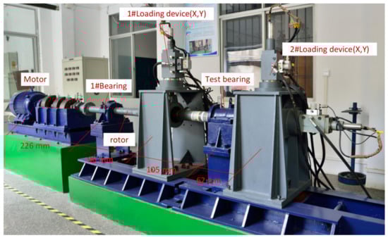
Figure 2.
Test rig.
The exciting force and response are measured for the bearing dynamic characteristic experiment, as shown in Figure 3. A pressure sensor is provided at the hydraulic cylinder to measure the exciting force. One displacement section is set at both sides of the test bearing, and two eddy current sensors are set at each section to measure the vibration in the horizontal direction and vertical direction, respectively, as shown in Figure 4.
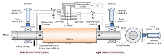
Figure 3.
Measurement scheme.
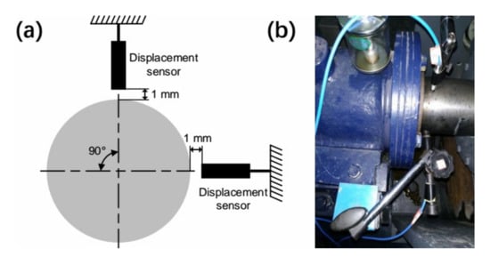
Figure 4.
Eddy current sensors arrangement: (a) test section arrangement, (b) physical layout.
In addition, an eddy current sensor (Type ZA-210803, Zhuzhou Zhonghang Technology Development Co., Ltd, Zhuzhou, China) is set to identify the phase. The sensitivity of the eddy current sensor is 5 V/mm and the maximum range is 2 mm. The data acquisition and analysis system for data acquisition is the sound and vibration-measuring instrument (Type 3053-B-120, Brüel & Kjær Sound and Vibration Measurement A/S, Nærum, Denmark), and the PULSE 17.1 (Brüel & Kjær Sound and Vibration Measurement A/S, Nærum, Denmark) software is used for signal spectrum analysis.
3. The Test Principle and Procedure
3.1. Shaft Bending Simulation Method
As shown in Figure 2, the hydraulic cylinder 2-Y applies a vertical static load on the right side of the test bearing, causing the right shaft to sink, thus simulating the shaft bending under cantilevered load from the propeller. The eddy current sensors in the vertical direction on both sides of the test bearing can measure the shaft position, and the equivalent inclination angle of the shaft can be converted according to the shaft movement. When the shaft does not rotate, a static load of 18 kN is applied on the right side, and the distance changes between the eddy current sensors on both sides of the test bearing and the shaft are shown in Figure 5. It can be seen that the position changes of the left and right sides after loading are −0.002 mm and +0.132 mm respectively, indicating that when the right side of the shaft sinks due to the right load, the left side raises slightly. Compared with Figure 5, when the shaft rotates (50 r/min, as shown in Figure 5), although the displacement signals on both sides of the shaft fluctuate due to the shaft vibration, the step change of the position caused by the load is obvious. Based on the mean values, it can be concluded that when the left side rises by 0.041 mm after loading, the right side sinks by 0.143 mm.
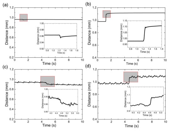
Figure 5.
Vertical position distance change of both sides of the test bearing: (a) left side—0 r/min; (b) right side—0 r/min; (c) left side—50 r/min; (d) right side—50 r/min.
3.2. Parameter Identification Method
For the test-rig shown in Figure 2, the linear assumption of the liquid film force is carried out first, that is, if there is a small disturbance (displacement and speed) in the static balance position, there will be an increment in the liquid film force. Then, the dynamic model of the test bearing system is established, and the exciting force and response are measured. Finally, the model is solved to obtain the stiffness and damping coefficients of the test bearing. The test bearing system is simplified, and the bearing is assumed to be two units, forming a two-fulcrum supporting model. The corresponding journal is assumed to be two journal units that interact with each other. Based on the assumption, a double-section distributed dynamic characteristic model is established. Unlike common bearings with 8 dynamic characteristic coefficients, there are 16 dynamic characteristic coefficients in the model. In Figure 6, ml and mr are the masses of the left and right bearing units, respectively, and [Kl,Cl] and [Kr,Cr] are the stiffness matrix and damping matrix of the left and right bearing units, respectively.
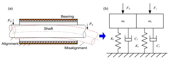
Figure 6.
Dynamic model of the test bearing system: (a) structure of large aspect ratio bearing; (b) dynamic model of two-fulcrum supporting.
During the test, a static load Fs is applied on the right side of the test bearing to bend the shaft, and a dynamic load Fd is applied on the left side of the test bearing to provide the exciting force for the test bearing system. The form and algorithm of the dynamic equation of the bearing system depend on the excitation method. Two excitation methods are proposed.
- (1)
- 4-time vertical excitation method
When the first vertical exciting force F1(t) is applied to the shaft, the displacement response x1l and y1l of the left shaft unit and the displacement response x1r and y1r of the right shaft unit can be obtained. The dynamic model of the test bearing is as follows:
Fourier-transforming Equation (1):
It can be seen from Equation (2) that for each vertical excitation, the time and frequency domain data of the exciting force, the horizontal displacement of two sides, and the vertical displacement of two sides can be obtained. Then, four linear equations are established. To identify 16 dynamic characteristic coefficients of the bearing, 16 linear equations should be established. Therefore, four times of excitation are required to establish a complete equation set. Similar to the first excitation, when the vertical exciting forces F2(t), F3(t), and F4(t) are applied to the shaft, the displacement responses of the left bearing unit are x2l, y2l, x3l, y3l, x4l, y4l and those of the right bearing unit are x2r, y2r, x3r, y3r, x4r, y4r, which can lead to the corresponding function Hx2l(w2), Hy2l(w2), Hx3l(w3), Hy3l(w3), Hx4l(w4), Hy4l(w4), etc. The dynamic equations of the bearing system after three times of excitation are Fourier-transformed, as follows:
By combining the above Equations (3)–(5) and separating the real and virtual parts:
where
By solving Equations (6) and (7), the 16 dynamic characteristic coefficients of the bearing can be obtained. Taking the first vertical excitation (excitation frequency of 1.5 Hz) with a rotational speed of 100 r/min as an example, the force and displacement are shown in Figure 7, in which the DC component in the frequency-domain graph has been filtered out. It can be seen that the horizontal and vertical responses can be obtained at the same time by a single vertical excitation. Therefore, in an ideal state, the above identification method is feasible. However, the response data in the horizontal direction have a small amplitude, which will lead to a large identification error when the SNR (Signal-Noise Ratio) is low [26]. Moreover, in addition to the excitation frequency of 1.5 Hz, the frequency-domain graph also has a larger amplitude of a 1.7 Hz spectral component, which may be caused by vibration of the test-rig. This frequency component will weaken the energy of the excitation frequency, thus affecting the identification accuracy [27,28].
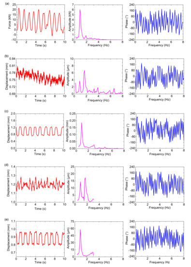
Figure 7.
Time and frequency domain diagrams of 1 excitation force and 4 displacements: (a) Vertical excitation force; (b) horizontal displacement on the left side; (c) vertical displacement on the left side; (d) horizontal displacement on the right side; (e) vertical displacement on the right side.
- (2)
- 8-time cross excitation method
To solve the problem of small response in the horizontal direction in the multi-time vertical excitation method, the cross-excitation method is proposed, that is, each group of cross excitation includes one vertical excitation and one horizontal excitation. First, vertical excitation is applied. Ignoring the response in the horizontal direction, an equation is obtained:
At the same time, the horizontal excitation of the same frequency is applied. Ignoring the response in the vertical direction, an equation is obtained:
Combining Equations (8) and (9) can obtain:
It can be seen from Equation (13) that after each excitation, the response signal in that direction can be obtained, and then the frequency-domain data can be extracted. Four linear equations can be obtained by one group of cross excitation. Therefore, four groups of cross excitation are required to obtain 16 dynamic characteristic coefficients of the bearing, that is, the 8-time cross excitation method. Performing another three groups of cross excitation according to the same procedure as the first time, the following equations are obtained:
By combining the above Equations (13)–(16) and separating the real and virtual parts:
where
By solving Equations (17) and (18), the 16 dynamic characteristic coefficients of the bearing can be obtained. Taking the first group of cross excitation with a rotational speed of 100 r/min as an example, the time and frequency domain graphs are shown in Figure 8 and Figure 9, in which the DC component in the frequency-domain graph has been filtered out. It can be seen that the horizontal response obtained by the cross excitation is significantly greater than that of single vertical excitation, and the amplitude of the excitation frequency is the largest, with good SNR. In addition, because the exciting force is applied on the left side, the response of the left side is greater than that of the right side.
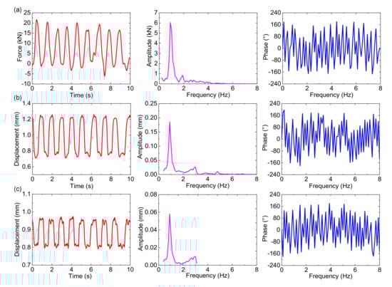
Figure 8.
Time and frequency domain diagrams of vertical excitation and response: (a) Vertical excitation force; (b) vertical displacement on the left side; (c) vertical displacement on the right side.
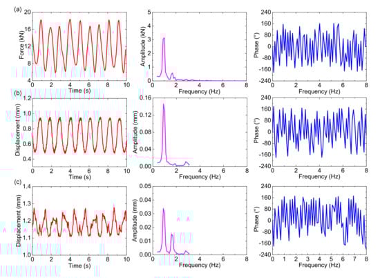
Figure 9.
Time and frequency domain diagrams of horizontal excitation and response: (a) Horizontal excitation force; (b) horizontal displacement on the left side; (c) horizontal displacement on the right side.
3.3. The Test Procedure
According to the identification model of distributed dynamic characteristic coefficients of the bearing, the excitation method, excitation frequency, shaft bending, and rotational speed are the important factors. Therefore, the effect tests of the above factors are carried out. The excitation frequency of the 4-time vertical excitation method is 1.5 Hz. The 8-time cross excitation method is adopted for the test of shaft bending and variable speed. In the test without considering the shaft bending, the static load Fs applied on the right shaft is 0 N, and the rotational speed is increased from 50 r/min to 225 r/min, each time by 25 r/min. At each rotational speed, the horizontal and vertical excitation of 1 Hz, 1.5 Hz, 2 Hz, and 2.5 Hz are applied to the left shaft. In vertical excitation, one force signal and four displacement signals in horizontal and vertical directions on both sides of the test bearing are acquired. In horizontal excitation, one force signal and two displacement signals in the horizontal direction on both sides of the bearing are acquired. The above signal acquisition methods ensure that the running state of the bearing is almost the same for the two excitation methods. The procedure of the alignment test is similar to the misalignment test, except that the former requires a static load of 18 kN on the right shaft.
4. Experiment Results and Discussion
4.1. The Effect of Excitation Method
The rotational speeds are 50 r/min and 225 r/min, respectively, and the bearing stiffness coefficients identified by the two excitation methods are shown in Figure 10. It can be seen that there is only a small difference between the cross stiffness coefficients obtained by the two methods, but the main stiffness coefficients differ greatly. At 50 r/min, the difference between the two identification values of kyyl and kyyr is 2.05 × 10⁷ N/m and 2.25 × 10⁷ N/m, respectively, while that of kxxl and kxxr is 3.44 × 10⁷ N/m and 3.60 × 10⁷ N/m respectively. At 225 r/min, the difference between the two identification values of kyyl and kyyr is 2.20 × 10⁷ N/m and 3.80 × 10⁷ N/m, respectively, and that between the two identification values of kxxl and kxxr is 3.05 × 10⁷ N/m and 3.83 × 10⁷ N/m, respectively. Moreover, the difference between the two identification values of the vertical main stiffness coefficient is smaller than that of the horizontal main stiffness coefficient. This proves the above defects of the four-time vertical excitation method. No horizontal excitation is carried out in the four-time vertical excitation method. Under the effect of cross stiffness, only a small response is generated in the horizontal direction. It can also be seen from Figure 6 that the SNR of the response signal is small, resulting in an obvious interference to amplitude and phase identification of the response. It can be seen from Equations (6) and (7) that kxxl and kxxr are related to S1 and H, which are related to the horizontal response. For this cause, kxxl and kxxr are sensitive to the error of the horizontal response. kyyl and kyyr are related to S2 and H, but S2 is unrelated to the horizontal response. The difference between the kyyl and kyyr results measured by the two excitation methods at 50 r/min is 2.05 × 10⁷ N/m and 2.25 × 10⁷, but the difference increases to 2.2 × 10⁷ N/m and 3.8 × 10⁷ N/m at 225 r/min, respectively, indicating that the increase in unbalanced forces caused by the increase in speed has a great impact on the identification results. Therefore, the difference in the identification values of kxxl and kxxr between the two excitation methods is relatively small.
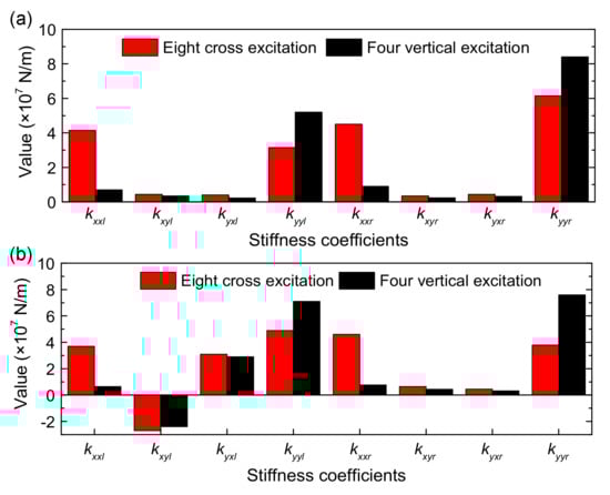
Figure 10.
Bearing stiffness coefficients under two excitation methods: (a) 50 r/min; (b) 225 r/min.
As shown in Figure 11, the bearing damping coefficients identified by the two excitation methods are consistent with the law of the stiffness coefficients. The difference in the main damping coefficients obtained by the two methods is significantly greater than the cross damping coefficients, and the difference in the horizontal main damping coefficient is greater than that of the vertical main damping coefficient. At 50 r/min, the difference between the two identification values of cxxl and cxxr is 6.95 × 10⁷ N/m and 7.83 × 10⁷ N/m, respectively, which is far greater than 0.45 × 10⁷ N/m and 0.67 × 10⁷ N/m obtained by the four-time vertical vibration method. The simulation results of Reference [26] can explain this phenomenon; when the phase identification error is 1°, the identification error of stiffness coefficient is less than 1%, but that of damping coefficient is 10~20%. Due to the low SNR of the horizontal response and the large phase identification error of the four-time vertical vibration method, the identification error of the damping coefficient in the horizontal direction is large. Meanwhile, equipment installation errors (misalignment) and model assumption errors (nonlinear oil film system is assumed to be linear oil film system) will also affect the identification accuracy. In addition, as the rotational speed increases, the shaft unbalanced excitation and its response also increase, which reduces the difference between the horizontal damping coefficients obtained by the two methods. In summary, to reduce the identification error, the eight-time cross excitation method is adopted in the subsequent tests.
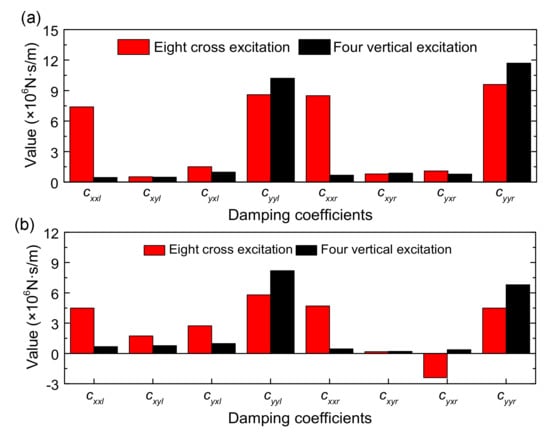
Figure 11.
Bearing damping coefficients under two excitation methods: (a) 50 r/min; (b) 225 r/min.
4.2. The Effect of Excitation Frequency
According to Equations (17) and (18) of the eight-time cross excitation method, some relevant terms of the excitation frequency w are introduced in the frequency domain analysis. For example, −mw2 is introduced in the inertial force term and iw in the damping force term. In such a case, the change in excitation frequency will affect the identification results of the stiffness and damping coefficients. When the rotational speed is 150 r/min, the horizontal and vertical excitation of 1 Hz, 1.5 Hz, 2 Hz, and 2.5 Hz, the horizontal and vertical excitation of 2 Hz, 2.5 Hz, 3 Hz, and 3.5 Hz, and the horizontal and vertical excitation of 3 Hz, 3.5 Hz, 4 Hz and 4.5 Hz are applied to the left shaft, and the signals are acquired and processed, as shown in Figure 12. It can be seen that with the increase in the excitation frequency, the stiffness coefficients of the bearing increase and the damping coefficients decrease, with a small variation amplitude. In addition, the horizontal damping coefficient cxxr of the right side presents a negative value under the frequency between ~1 and ~2.5 Hz, which is due to the introduction of the terms about w on the FFT transform of the bearing time-domain dynamic equation. Therefore, it is necessary to select a reasonable excitation frequency during the test. The resonance frequency and rotational frequency of the test system should be avoided for the excitation frequency.
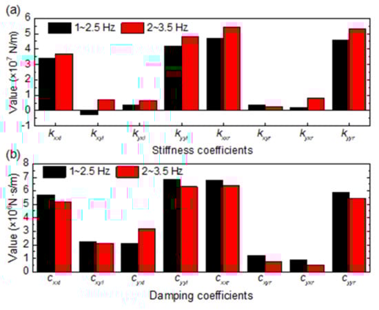
Figure 12.
Relationship between dynamic characteristic coefficients of bearing and excitation frequency: (a) stiffness coefficients; (b) damping coefficients.
4.3. The Effect of Shaft Bending
The shaft misalignment and alignment are simulated when the static load on the right side of the test bearing is 0 kN and 18 kN, respectively. The eight-time cross excitation method is adopted and the identification results are shown in Figure 13. When the rotational speed is 50 r/min, for the test results of shaft misalignment, the stiffness coefficients of the right bearing unit is slightly greater than those of the left bearing unit due to a misaligned installation and unbalanced force of the shaft, indicating that the bearing with a large aspect ratio is sensitive to the spatial position of the shaft. Compared with the test results without static load, kxyl, kyxl, and kyyl with static load are slightly lower, but kxxr, kxyr, kyxr, and kyyr increase significantly by 100%, 253%, 1195%, and 237% respectively, indicating that shaft bending can significantly change the distribution of dynamic characteristic coefficients along the axial direction. The reason is that after the right side of the bearing is loaded, the journal on the left side rises slightly, and the journal on the right side sinks significantly (as shown in Figure 6). The eccentricity of the left bearing unit is slightly reduced, resulting in a slight reduction in the stiffness coefficient. The eccentricity of the right bearing unit increases significantly and the stiffness coefficient of the right bearing unit increases rapidly, because the bearing capacity is sensitive to displacement disturbance.
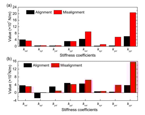
Figure 13.
Bearing stiffness coefficients with shaft state at two rotational speeds: (a) 50 r/min; (b) 225 r/min.
When the rotational speed is 225 r/min, the change trend of the bearing stiffness coefficients after applying static load is similar to that at 50 r/min, and kxxr, kxyr, kyxr, and kyyr increase by 41%, 22%, 767%, and 311%, respectively. This shows that the increase in speed ensures that the distribution of stiffness coefficients along the axial direction is more uniform, weakening the effect of shaft bending on the increase in stiffness coefficients of the right bearing unit, which is due to the enhancement of the hydrodynamic lubrication effect of the bearing and reduction in the asperity contact. Meanwhile, the increase in rotational speed enhances the excitation effect of the unbalanced force, which leads to the large relative increase in kyyr.
As shown in Figure 14, the test results of damping coefficients under the two shaft states show that the change law of the damping coefficient is similar to that of the stiffness coefficient. When the speed is 50 r/min, and when the right side of the shaft is not loaded, the damping coefficients of the left and right bearing units are close. When the right side is loaded, the shaft bending results in a slight decrease in the damping coefficient of the left bearing unit, while the damping coefficient of the right bearing unit increases significantly, and cxxr and cyyr increase by 25% and 64%, respectively, indicating that the increase in the extrusion effect at the right bearing strengthens the damping of the water film. In addition, when the rotational speed is increased to 225 r/min, the increase in the damping coefficient of the right bearing unit decreases, and the distribution of the damping coefficient along the axial direction is more uniform, signifying that the enhancement of the hydrodynamic effect makes the pressure distribution become more uniform. To summarize, shaft bending will lead to a significant increase in local bearing dynamic characteristic coefficients, in which the relative increase in the stiffness coefficient is greater than the damping coefficient, and the increase in rotational speed weakens the effect of shaft bending, so the uneven distribution of dynamic characteristic coefficients of the bearing caused by shaft bending at low speed is more significant.

Figure 14.
Bearing damping coefficients with shaft state at two rotational speeds: (a) 50 r/min; (b) 225 r/min.
4.4. The Effect of Rotational Speed
When no static load is applied to the right side of the bearing, that is, when the shaft bending is not considered, the eight-time cross excitation method is adopted, and the identification results at different rotational speeds are shown in Figure 15. It can be seen that in the range of 50~200 r/min, the magnitude of the main stiffness coefficients is 107 N/m, and that of the cross stiffness coefficients is 106 N/m, and the vertical main stiffness coefficient is slightly larger than the horizontal main stiffness coefficient. When the shaft bending is not considered, the stiffness coefficients of the left and right bearing units are close, and the variation with the speed is small. As the rotation rate speeds, the horizontal stiffness coefficient of the left bearing unit decreases slightly, the vertical main stiffness coefficient increases slightly, and the cross stiffness coefficients fluctuate slightly. As there is no load on the right side, the shaft moves freely. Under the effect of rotor imbalance and misaligned installation, the shaft on the left side sinks slightly with the increase in rotational speed, which results in a slight increase in the vertical main stiffness coefficient of the left bearing unit. Moreover, the stiffness coefficient of the right bearing unit decreases with the increase in the rotational speed but increases slightly under certain working conditions, which is the joint action of the installation and rotational speed. In general, the increase in rotational speed reduces the eccentricity of the shaft, thus reducing the stiffness coefficient, but it also increases the eccentricity when the shaft section sinks, resulting in the opposite result.
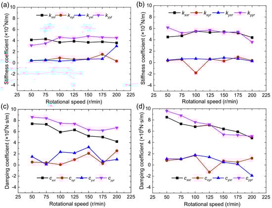
Figure 15.
The relationship between the dynamic characteristic coefficient and rotational speed: (a) Stiffness coefficient of left bearing unit; (b) stiffness coefficient of right bearing unit; (c) damping coefficient of left bearing unit; (d) damping coefficient of right bearing unit.
As shown in Figure 15c,d, the magnitude of the main damping coefficients is 106 N s/m, and that of the cross damping coefficients is 105 N s/m. Furthermore, the vertical main damping coefficient is slightly greater than the horizontal main damping coefficient. As the rotation rate goes up, the main damping coefficients of the left and right bearing units decrease significantly, which is caused by the decrease in the squeeze effect of the bearing oil film due to the increase in the rotational speed.
5. Conclusions
To identify distributed dynamic characteristic coefficients of bearings with a large aspect ratio under shaft bending, a double-section loading method simulating shaft bending and excitation is developed, two identification methods of distributed dynamic characteristic coefficients are put forward, and the identification experiment is carried out. As for the particular investigated bearing, some meaningful conclusions have been obtained.
- (1)
- The response amplitude of the four-time vertical excitation method in the horizontal direction is small, and it is vulnerable to the interference of the vibration of the test-rig, resulting in a large identification error of the stiffness and damping coefficients in the horizontal direction. The eight-time cross excitation method can overcome the problem with high SNR and identification accuracy.
- (2)
- When the cantilevered load is not applied, the dynamic characteristic coefficients of the bearing is evenly distributed along the axial direction, the stiffness coefficient fluctuates slightly with the increase in the rotational speed, and the main damping coefficient decreases significantly with the increase in the rotational speed. In the range of 50~200 r/min, the magnitude of the main stiffness coefficients, cross stiffness coefficients, main damping coefficients, and cross damping coefficients are 107 N/m, 106 N/m, 106 N s/m, and 105 N s/m, respectively.
- (3)
- Shaft bending will lead to a significant increase in the local dynamic characteristic coefficients of the bearing, in which the relative increase in the stiffness coefficient is greater than the damping coefficient. The increase in the rotational speed will weaken the effect of shaft bending, and the key factors causing an uneven distribution of the bearing dynamic characteristic coefficients are the shaft bending and the large aspect ratio under low speed and cantilevered load.
- (4)
- Future work is needed to improve the identification accuracy of dynamic characteristic coefficients from the perspective of frequency and the method of excitation.
Author Contributions
W.O. provided the Conceptualization; G.W. formulated the methodology; Q.L. designed the software; Q.L. carried out validation; Q.C. performed the formal analysis; Y.J. performed the investigation; W.O. contributed the resources; Q.L. analyzed the data; Q.C. contributed writing—the original draft preparation,; W.O. contributed writing—the review and editing; Q.C. contributed visualization; G.W. and Y.J. contributed the supervision; Y.J. contributed project administration; W.O contributed the funding acquisition. All authors have read and agreed to the published version of the manuscript.
Funding
This research was funded by the National Key Research and Development Project of China (No. 2018YFE0197600) and the National Defense Pre-Research Foundation of China (No. 61402100402).
Institutional Review Board Statement
Not applicable.
Informed Consent Statement
Not applicable.
Data Availability Statement
Not applicable.
Conflicts of Interest
The authors declare no conflict of interest. The funders had no role in the design of the study; in the collection, analyses, or interpretation of data; in the writing of the manuscript, or in the decision to publish the results.
References
- Chen, F.; Chen, Y.; Hua, H. Vibration analysis of a submarine elastic propeller-shaft-hull system using FRF-based substructuring method. J. Sound. Vib. 2019, 443, 460–482. [Google Scholar] [CrossRef]
- Litwin, W. Marine propeller shaft bearings under low-speed conditions: Water vs. oil lubrication. Tribol. Trans. 2019, 62, 839–849. [Google Scholar] [CrossRef]
- Kuang, F.; Zhou, X.; Huang, J.; Wang, H.; Zheng, P. Machine-vision-based assessment of frictional vibration in water-lubricated rubber stern bearings. Wear 2019, 426, 760–769. [Google Scholar] [CrossRef]
- Liang, X.; Yan, X.; Liu, Z. Effect of perturbation amplitudes on water film stiffness coefficients of water-lubricated plain journal bearings based on CFD-FSI methods. Proc. Inst. Mech. Eng. Part J J. Eng. Tribol. 2019, 233, 1003–1015. [Google Scholar] [CrossRef]
- Feng, H.; Jiang, S.; Jia, A. Investigations of the static and dynamic characteristics of water-lubricated hydrodynamic journal bearing considering turbulent, thermohydrodynamic and misaligned effects. Tribol. Int. 2019, 130, 245–260. [Google Scholar] [CrossRef]
- Lv, F.; Jiao, C.; Ta, N.; Rao, Z. Mixed-lubrication analysis of misaligned bearing considering turbulence. Tribol. Int. 2018, 119, 19–26. [Google Scholar] [CrossRef]
- He, T.; Zou, D.; Lu, X.; Guo, Y.; Wang, Z.; Li, W. Mixed-lubrication analysis of marine stern tube bearing considering bending deformation of stern shaft and cavitation. Tribol. Int. 2014, 73, 108–116. [Google Scholar] [CrossRef]
- Lund, J. Review of the concept of dynamic coefficients for fluid film journal bearings. J. Tribol. 1987, 109, 37–41. [Google Scholar] [CrossRef]
- Ouyang, W.; Cheng, Q.; Wang, L.; Jin, Y. Experimental research on distributed dynamic characteristics of water-lubricated stern bearing under offset load. J. Traffic Transp. Eng. 2019, 19, 92–100. [Google Scholar] [CrossRef]
- Liu, S.; Yang, B. A new model of water-lubricated rubber bearings for vibration analysis of flexible multistage rotor systems. J. Sound. Vib. 2015, 349, 230–258. [Google Scholar] [CrossRef]
- Dimond, T.; Sheth, P.; Allaire, P.; He, M. Identification methods and test results for tilting pad and fixed geometry journal bearing dynamic coefficients–A review. Shock Vib. 2009, 16, 13–43. [Google Scholar] [CrossRef]
- Jiang, G.; Hu, H.; Xu, W.; Jin, W.; Xie, Y. Identification of oil film coefficients of large journal bearings on a full scale journal bearing test rig. Tribol. Int. 1997, 30, 789–793. [Google Scholar] [CrossRef]
- Delgado, A.; Vannini, G.; Ertas, B.; Drexel, M.; Naldi, L. Identification and prediction of force coefficients in a five-pad and four-pad tilting pad bearing for load-on-pad and load-between-pad configurations. J. Eng. Gas. Turb. Power 2011, 133, 092503. [Google Scholar] [CrossRef]
- Dmochowski, W.; Brockwell, K. Dynamic testing of the tilting pad journal bearing. Tribol. T. 1995, 38, 261–268. [Google Scholar] [CrossRef]
- Reddy, D.; Swarnamani, S.; Prabhu, B. Experimental investigation on the performance characteristics of tilting pad journal bearings for small L/D ratios. Wear 1997, 212, 33–40. [Google Scholar] [CrossRef]
- Ciulli, E.; Forte, P. Nonlinear response of tilting pad journal bearings to harmonic excitation. Machines 2019, 7, 43. [Google Scholar] [CrossRef] [Green Version]
- Matta, P.; Arghir, M. Identification method for rotordynamic coefficients of cylindrical air bearing using an impact hammer. Inst. Mech. Eng. Part J J. Eng. Tribol. 2012, 226, 199–212. [Google Scholar] [CrossRef]
- Chatterton, S.; Pennacchi, P.; Dang, P.; Vania, A. Identification dynamic force coefficients of a five-pad tilting-pad journal bearing. In Proceedings of the 9th IFToMM International Conference on Rotor Dynamics, Milan, Italy, 22–25 September 2014; Springer: Cham, Switzerland, 2015; pp. 931–941. [Google Scholar] [CrossRef]
- Chen, C.; Jing, J.; Cong, J.; Dai, Z. Identification of dynamic coefficients in circular journal bearings from unbalance response and complementary equations. Proc. Inst. Mech. Eng. Part J J. Eng. Tribol. 2018, 233, 1016–1028. [Google Scholar] [CrossRef]
- Tiwari, R.; Lees, A.; Friswell, M. Identification of speed-dependent bearing parameters. J. Sound Vib. 2002, 254, 967–986. [Google Scholar] [CrossRef] [Green Version]
- Zhang, M.; Yu, L.; Xu, Z.; Xu, R. Experimental research on identification of oil-film dynamic coefficients of large-size journal bearings. In Proceedings of the IEEE International Conference on Automation and Logistics, Shenyang, China, 5–7 August 2009; pp. 1099–1103. [Google Scholar] [CrossRef]
- Mao, W.; Han, X.; Liu, G.P.; Liu, J. Bearing dynamic parameters identification of a flexible rotor-bearing system based on transfer matrix method. Inverse Probl. Sci. Eng. 2016, 24, 372–392. [Google Scholar] [CrossRef]
- Liu, S.; Yang, B. Optimal placement of water-lubricated rubber bearings for vibration reduction of flexible multistage rotor systems. J. Sound Vib. 2017, 407, 332–349. [Google Scholar] [CrossRef]
- Liu, S.; Yang, B. Vibrations of flexible multistage rotor systems supported by water-lubricated rubber bearings. J. Vib. Acoust. 2017, 139, 21016. [Google Scholar] [CrossRef]
- Ouyang, W.; Zhang, X.; Jin, Y.; Yuan, X. Experimental study on the dynamic performance of water-lubricated rubber bearings with local contact. Shock Vib. 2018, 2018, 6309727. [Google Scholar] [CrossRef] [Green Version]
- Ouyang, W.; Peng, L.; Chen, R.; Yuan, X. Simulated identification on dynamic characteristics of large heavy-load bearing. J. Vibroengineering 2017, 19, 3230–3242. [Google Scholar] [CrossRef]
- Zhou, W.; Zhao, Y.; Yuan, H.; Liu, J.; Wang, X. Research on the Contact Pressure Calculation Method for the Misaligned Elastomeric Journal Bearing. J. Mar. Sci. Eng. 2022, 10, 141. [Google Scholar] [CrossRef]
- Tian, Y.; Zhang, C.; Yang, L.; Ouyang, W.; Zhou, X. Analysis of Vibration Characteristics of Podded Propulsor Shafting Based on Analytical Method. J. Mar. Sci. Eng. 2022, 10, 169. [Google Scholar] [CrossRef]
Publisher’s Note: MDPI stays neutral with regard to jurisdictional claims in published maps and institutional affiliations. |
© 2022 by the authors. Licensee MDPI, Basel, Switzerland. This article is an open access article distributed under the terms and conditions of the Creative Commons Attribution (CC BY) license (https://creativecommons.org/licenses/by/4.0/).