Article

Strut-and-Tie Model and Numerical Simulation of Sleeve Grouting Connection for Concrete-Filled Steel Tube Column

1
School of Civil and Transportation Engineering, Hebei University of Technology, Tianjin 300401, China
2
College of Civil and Architectural Engineering, North China University of Science and Technology, Tangshan 063210, China
*
Author to whom correspondence should be addressed.
J. Mar. Sci. Eng. 2022, 10(5), 629; https://doi.org/10.3390/jmse10050629
Submission received: 26 March 2022 / Revised: 28 April 2022 / Accepted: 3 May 2022 / Published: 5 May 2022
(This article belongs to the Section Ocean Engineering)

Abstract

:
To study the performance and failure mechanisms of concrete-filled steel tube (CFST) column sleeve grouting connections, theoretical analysis and finite element simulation were performed for the structure in the connection. In this paper, a theoretical strut-and-tie model suitable for calculation of the axial compression capacity of sleeve grouting connections was proposed. High-precision numerical models were established to verify the applicability of the strut-and-tie model and the rationality of parameter selection in the sleeve grouting connection. The parameters include the shear key height, shear key shape, shear key distance, and grouting material strength. The results showed that the prediction values of the strut-and-tie model accorded well with the experimental values and simulated values. The average ratio of the calculated values based on the ACI and EC2 codes to experimental values were 1.07 and 1.09, respectively. An increase in the shear key height can improve the axial compression capacity of the sleeve grouting connection, and it was suggested that the range of the shear key height was reasonable at 2~3 mm. The shear key shapes of semicircular, rectangular vertical and trapezoidal were recommended, which can meet the requirements of sleeve grouting connections of CFST columns. The load-transmitting behavior of rectangular vertical shear keys was better due to the insignificant stress concentration. The rectangular horizontal form of shear keys is not recommended since it has the worst load transmission. The shear key height-to-distance ratios were recommended to be 0.044~0.1, the amplitude of the strength attenuation was different only after failure, and all models showed good ductility and compression capacity. With the increase in grouting material strength, the axial compression capacity of the sleeve grouting connection increased. It is reasonable to use grouting material strengths C50 to C90 for the sleeve grouting connection.

1. Introduction

A concrete-filled steel tube (CFST) column is an economical and reasonable structure [1]. It contributes to the improvement of construction efficiency and the realization of industrial production. Sleeve grouting connections were used to connect column to column. The sleeve grouting connections are also the key component of the support structure for offshore wind turbines. For the offshore wind turbine foundation with water depth ranging from 10 to 60 m, sleeve grouting connection was needed to connect the wind turbine foundation with the transition section [2]. Liu et al. [3,4] studied the axial compression performance of prefabricated core steel tube reinforced concrete columns, and compared with the integral pouring column, the ultimate bearing capacity and deformation capacity were all improved. Chen et al. [5,6] proposed a new prefabricated type of sleeve grouting connection method and applied it to composite shear walls, special-shaped columns, and other structures, showing good connection performance and seismic performance. Figure 1 shows the sleeve grouting connection of the CFST column. Shear keys were arranged on the outer wall of the steel tube and the inner wall of the sleeve in the connection. To increase the mechanical interaction load between the grouting material and steel tube, the connection performance of the sleeve grouting connection is improved.
According to the strut-and-tie model [7] and the experimental performance of the sleeve grouting connection [8], when the grouting material was destroyed along the shear keys in the connection, its strain field changed. The internal load of the connection was redistributed, and a conical section was formed. This is the region of stress and strain discontinuity, and the internal load of the region was determined by the strut-and-tie model. The discontinuous region of the strut-and-tie model was regarded as the D region [9,10], and its strain was nonlinear. D region is shown in the shaded part of Figure 2, where F is the concentrated load and Q is the distributed load [11].
In the 1980s and 1990s, a detailed study was carried out on the strut-and-tie model [12,13], corresponding two-dimensional [14,15] and three-dimensional models [16] were established for the study of the strut, tie and node in the model, and the calculation methods were determined. The study showed that the strut-and-tie model had good applicability in the D region [17,18]. Reasonable load transmission paths can be established [19].
The strut-and-tie model has been gradually applied to the stress analysis of pile caps [20,21,22,23,24], deep beams [25,26,27,28,29,30,31,32] and beam-column joints [33,34]. However, these have not involved the application of the strut-and-tie model to the sleeve grouting connection.
The sleeve grouting connection of CFST columns conforms to the basic characteristics of using truss elements to establish the strut-and-tie model, but there have been few studies on the use of strut-and-tie models for the calculation of the axial compression capacity of sleeve grouting connections. The applicability of the model and the key parameters are not clear. Therefore, based on the theory of the strut-and-tie model, a reasonable model was established to analyze the sleeve grouting connection. The numerical model was established. The influence of the shear key height, shear key distance, shear key shape, and shear key strength of the grouting material on its mechanical properties was analyzed and compared with experimental and theoretical calculation results to verify the rationality of the strut-and-tie model. This work provides a theoretical reference for calculating the ultimate bearing capacity and structural optimization of sleeve grouting connections.

2. Strut-and-Tie Model

Figure 3 shows the strut-and-tie model of the sleeve grouting connection for a CFST column. The steel tube was subjected to the axial load Pu. When the grouting material was damaged, oblique cracks beginning with shear keys appeared [35,36]. The crack angle θ was approximately 45°. Oblique cracks divided the grouting material into several closed annular sectors to transfer loads. Consider these annular sectors as struts to transfer loads. Since the cross-sectional area of the strut is the smallest at the position of contact with the steel tube, the compression failure of this section is considered the standard of the axial compression capacity of the strut.
In Figure 3a, the cracked grouting material is regarded as three struts. Their axial loads are Fns1, Fns2, and Fns3, respectively. The axial load of each strut is equal. The sum of the vertical components of the axial loads of struts is equal to Pu. The calculation formula of the bearing capacity of a single strut is shown in Equation (1).
Fns1 = Fns2 = Fns3 = Pu/3sinθ
Figure 3b is the simplified mechanical model. The strut and node form a truss model, which is in balance with Pu and the reaction load of the support. The load on the strut and node can be calculated by using the theory of the truss model.

2.1. Strut-and-Tie Model Based on ACI Code

The strut-and-tie model is included in the appendix to the ACI code [14]. Equation (2) is the bearing force calculation formula of the struts, ties and nodes listed in the code.
ØFnFu
where Fn is the nominal bearing force of the strut, tie or node, Fu is the external load, Ø is the bearing force reduction coefficient, and the value is 0.7. Only when Equation (2) meets the requirements is the strut-and-tie model in equilibrium.

2.1.1. Nominal Bearing Force of the Strut

The nominal bearing force of the strut is shown in Equation (3).
Fns = fceAcs = 0.85βsfcAcs
where Fns is the nominal bearing force of the strut, fce is the nominal strength of concrete, fc′ is the concrete cylinder compressive strength, Acs is the cross-sectional area of the strut close to the steel tube wall, and the value is equal to the width of the strut multiplied by the circumference of the strut close to the steel tube wall. βs is a coefficient which is related to the type of strut, the value of βs is 1.0, since the cross-sectional area of the strut along length was uniform in this paper. Equation (4) is the expression of Acs.
Acs = π(Dg + h)ωc
Equations (5) and (6) can be derived from Equations (2) and (3):
ØFns = ØfceAcs = Ø0.85βsfc′AcsFns1
A cs     F ns 1 / Ø 0.85 β s f c
According to Equations (4)–(6), the width of the strut can be calculated by Equation (7).
ωcPu/cπ(Dg + h)Ø0.85βsfc’sinθ
where ωc is the width of the strut, Dg is the steel tube diameter, h is the height of the shear key, and c is the total number of struts. Figure 4 shows the sleeve grouting connection. The shape of the node is a right triangle, and the length of the right-angle side is equal to the width of strut ωc. The angle between the strut and the horizontal line θ is 45°. The contact length between the node and the steel tube can be calculated by the width of the strut.

2.1.2. Nominal Bearing Force of Tie

The nominal bearing force of the tie is shown in Equation (8).
Fnt = fyAts
where Fnt is the nominal bearing force of the tie, fy is the yield strength of the tie, and Ats is the cross-sectional area of the tie. In the sleeve grouting connection, the tie can be regarded as a steel tube or sleeve, so Ats is defined as the cross-sectional area of the steel tube or sleeve. According to Equation (1):
ØFnt = ØfyAtsFt
where Ft is the actual bearing force on the tie.

2.1.3. Nominal Bearing Force of Node

The nominal bearing force of the node is shown in Equation (10).
Fnn = fceAnz
fce ≥ 0.85βnfc
where Fnn is the nominal bearing force of the node, Anz is the cross-sectional area of the node, and βn reflects the possibility of increasing the damage degree of the node caused by strain disharmony between the strut and tie.
Equation (12) can be deduced from Equations (2), (10) and (11):
ØFnn = ØfceAnz = Ø0.85βnfc′Ac ≥ Fn
where Fn is the actual bearing force on the node.

2.2. Strut-and-Tie Model Based on EC2 Code

2.2.1. Strength of the Strut

In the sleeve grouting connection of the CFST column, since the grout is located between the steel tube and the sleeve, it is in a state of trip-direction compression, which conforms to the characteristics of the transverse compressive stress of the strut in the EC2 code. Figure 5 shows that the strut of concrete is subjected to both axial and transverse compressive stresses. σRd,max is the axial stress of the concrete strut.
The strut bearing force formula of the EC2 code is as follows:
Fnc = υ′fcdAc = (1 − fck/250)fcdAc ≥ Fns1
Ac = π(Dg + h) ωc
where Fnc is the bearing force of the strut, υ’ is the reduction coefficient of the concrete compressive strength, fcd is the nominal compressive strength of the concrete, and Ac is the cross-sectional area of the strut close to the steel tube wall whose value is equal to the product of the width of the strut and the circumference close to the steel tube.

2.2.2. Bearing Force of Node

The compression node in the sleeve grouting connection is similar to the strut-and-tie model without anchor ties in the EC2 code. Therefore, the node bearing force is expressed in Equation (15).
Fn = k1υ′fcdAn
where Fn is the bearing force of the node, k1 is 1.0, and An is the sectional area perpendicular to the strut or tie, which is consistent with the calculation of Ac in Equation (14).

3. The Example Analysis

Table 1 shows the basic parameter information of the specimen in references [8,37], where L is the grouting connection length, s is the distance between two adjacent shear keys, h is the shear key height, and Pu is the axial compression capacity of the sleeve grouting connection.
Figure 6a shows the shear key arrangement of specimen 60a in the sleeve grouting connection. The shear keys welded to the steel tube and sleeve wall were arranged at equal heights. Figure 6b shows the shear key arrangement of specimen B3 in the sleeve grouting connection. The shear keys on the steel tube and sleeve wall are in a staggered arrangement.

3.1. Calculation of 60a Based on ACI Code

3.1.1. Strut Calculation of 60a Based on ACI Code

The strut width ωc calculated by Equation (7) is 17 mm. Based on the details of the node in Figure 4. The contact length between the node and the steel tube is 24 mm.
The grouting material of the connection has three major oblique cracks. According to the strut-and-tie model theory, the selected specimens are regarded as three struts of the same size, and Strut 1 is located between the first and second shear keys. Strut 2 is located between the second and third shear keys. Meanwhile, Region 1 and Region 2 can be combined together as the third strut, and the third strut is considered to have the same size and loading features as Strut 1 and Strut 2, as shown in Figure 7.
It can be deduced from Figure 4 that the sum of the contact length between the three struts and the steel tube wall is 72.0 mm so that the contact length L1 between one node and the steel tube wall is equal to the distance s between the two adjacent shear keys, as shown in Equation (16).
L1 = s
The distance between the first and the last shear keys on the steel tube wall is equal to the total length of contact between the steel tube and strut. The distance between the shear keys at both ends of specimen 60a is 57 mm, which is less than the sum of the contact length between the three struts and the steel tube of 72.0 mm. This shows that the assumed size of the strut is not enough to bear the load, and the calculated value of the axial compression capacity using the strut-and-tie model is less than the experimental value, so the calculation is relatively safe to use.
In specimen 60a, the contact length L1 is 19 mm, which is equal to the distance between adjacent shear keys, and the maximum width ωc can be calculated as 13.4 mm. The maximum strut width ωc is taken as the known condition. According to Equation (7), the axial compression capacity (Pu) of the sleeve grouting connection can be calculated as 385.8 kN. The axial compression capacity of the sleeve grouting connection is calculated based on the strut-and-tie model of ACI code, and the ratio between the calculated value and the experimental value is 0.79, indicating that the calculation is relatively safe to use.

3.1.2. Node Calculation of 60a Based on ACI Code

According to the experiment and the mechanical model in Figure 3, all three struts connected to the nodes are under pressure. Figure 8 shows a detailed drawing of a single node in the sleeve grouting connection.
It complies with the C-C-C node characteristics [38]. Therefore, βn is equal to 1. The sectional area of node Anz is 4396.9 mm2. According to Equation (10), the calculated value of node bearing force is 180.8 kN.
The sleeve grouting connection of specimen 60a can be regarded as three nodes, so that the bearing force of a single node is one third of the experimental value of the axial compression capacity. When the calculated value of node bearing force exceeds the experimental value, fracture failure of shear key did not occur, the node strength meets the requirements, so the strut fails before the node. Therefore, the axial compression capacity of the sleeve grouting connection is subject to the bearing force of the strut, and the sum of the bearing force of all of the struts is defined as the axial compression capacity of the sleeve grouting connection.
According to the experimental results [8], both the steel tube and the sleeve are subjected to axial compression, and the failure of the connection of the steel tube sleeve is caused by the cracking of the grouting material [14]. Therefore, the bearing force of the strut and the node is the main research object in the calculation of the specimens.

3.2. Calculation of B3 Based on ACI Code

3.2.1. Strut Calculation of B3 Based on ACI Code

Figure 9 shows the distribution method of the struts under a staggered arrangement of shear keys. Since there were three oblique cracks in the grouting material in the specimen [35], it can be considered that the four shear keys divide the grouting material into three struts. Strut 1 and Strut 2 are regarded as full-size struts. Region 1 and Region 2 are regarded as the third strut of the connection, and the three struts are considered to have the same size and loading characteristics. If the total length of contact between the three struts and steel tube is set as 2.5 times the shear key distance, then the contact length between each node and steel tube is shown in Equation (17).
L2 = 2.5s/3
L2 is the contact length between the node and the steel tube.
According to Equation (17), the sum of the contact length L2 is 112.5 mm. The sum of the bearing capacity of all struts within this range is defined as the axial compression bearing capacity of the sleeve grouting connection. According to the strut-and-tie model, there are three struts in the grouting material, so the contact length L2 is 37.5 mm. Based on Figure 4, the maximum width ωc of a single strut is 26.5 mm. According to Equation (7), the axial compression capacity (Pu) of the sleeve grouting connection is 810 kN. The ratio of the calculated value to the experimental value is 1.013. The calculated value is slightly larger than the experimental value, so it can be considered that for specimen B3, the load distribution method based on the strut-and-tie model can be used to calculate the axial compression capacity of the grouting sleeve connection in the case of a staggered shear key arrangement.

3.2.2. Node Calculation of B3 Based on ACI Code

According to Equation (10), the node bearing force is 381.9 kN, which exceeds the bearing force of the single strut, indicating that the node bearing force meets the requirements. The strut fails before the node, so the axial compression capacity of the sleeve grouting connection is subject to the bearing force of the strut.
Table 2 shows the comparison of the calculated values and experimental values based on the strut-and-tie model. In reference [8], the ratio between the calculated value and the experimental value ranges from 0.66 to 0.85, and the average ratio is 0.75. The ratios are close to each other with little change, indicating that the calculated values are relatively stable for the calculation of the specimen in reference [8]. In reference [37], the ratio between the calculated value and the experimental value ranges from 0.93 to 1.77, and the average ratio is 1.19. The strut-and-tie model based on the ACI code is applicable to the calculation of the axial compression capacity of the sleeve grouting connection.

3.3. Calculation of 60a Based on EC2 Code

3.3.1. Strut Calculation of 60a Based on EC2 Code

The maximum contact length between the node and the steel tube is 19 mm (equal to the shear key distances). Figure 4 shows that the maximum width of strut ωc is 13.4 mm. The strut-and-tie model is consistent with Figure 7. According to Equation (13), the maximum axial compression capacity of a single strut is 189.6 kN, and its vertical component is 134.0 kN. The vertical components of the three struts in the model are superimposed, which is the calculated value of the axial compression capacity of the sleeve grouting connection. The ratio of the calculated value of the axial compression capacity to the experimental value at 60a is 0.82.

3.3.2. Node Calculation of 60a Based on EC2 Code

According to Equation (16), the cross-sectional area of a single node Anz is 4396.9 mm2. The calculated value of the single node bearing capacity is 140.3 kN. It can be seen from the strut-and-tie model that 60a has three nodes. The calculated value of the axial compression capacity of the sleeve grouting connection is 420.9 kN. The ratio between the calculated value and the experimental value is 0.863. The calculated value of the bearing capacity of the node is less than the axial compression capacity of the sleeve grouting connection in the experiment, so the node will fail before the strut. Therefore, the axial compression capacity of the 60a sleeve grouting connection is subject to the bearing capacity of nodes; that is, the sum of the bearing capacity of all nodes is defined as the calculated bearing force of the sleeve grouting connection.

3.4. Calculation of B3 Based on EC2 Code

3.4.1. Strut Calculation of B3 Based on the EC2 Code

According to Equation (13), the axial compression capacity of a single strut is 395.2 kN, and its vertical component is 279.4 kN. Specimen B3 is regarded as having three struts. The sum of the vertical components of the axial compression capacity of all of the struts is defined as the axial compression capacity of the sleeve grouting connection, and the ratio of the calculated value to the experimental value is 1.049.

3.4.2. Node Calculation of B3 Based on EC2 Code

The calculated bearing capacity of a single node is 270.0 kN. According to the strut-and-tie model theory, specimen B3 has three nodes. The sum of the bearing capacity of all nodes is defined as the axial compression capacity of the sleeve grouting connection. Therefore, the node fails before the strut, and the sum of the bearing capacity of all nodes is taken as the axial compression capacity of the sleeve grouting connection.
The specimens in references [8,37] are calculated based on the strut-and-tie model of the EC2 code. Table 3 shows the comparison between the calculated values and the experimental values. The calculated values of the specimens in reference [8] are all less than the experimental values. Compared with the model based on the ACI code, the calculation accuracy is slightly improved, but the theoretical calculation is still conservative. In reference [37], the ratio of calculated values to experimental values ranges from 0.93 to 1.78, and the average ratio is 1.20. The calculation accuracy is basically the same as that of the strut-and-tie model based on the ACI code. This indicates that the strut-and-tie model based on the EC2 code has certain applicability to the calculation of the axial compression capacity of the sleeve grouting connection.
Figure 10 shows the comparison between the calculated values and experimental values of the axial compression capacity of the specimens in references [8,37] based on the ACI code and EC2 code. A reference line with an angle of 45 degrees is drawn in the figure. The calculated values of the specimens in reference [8] are all less than the experimental values. 83.3% of the calculated values in reference [37] are greater than the experimental values. After the experimental value of the axial compression capacity exceeds 800 kN, the calculated values of the four specimens deviate from the experimental values, and the rest are close to the experimental values.

4. Numerical Analyses

To study the influence of shear key height, shape, grouting material strength and shear key distance on the axial compression capacity of the sleeve grouting connection and to further verify the applicability of the strut-and-tie model to the calculation of axial compression capacity for the sleeve grouting connection of a CFST column, finite element models of relevant specimens in references [8,37] were established, and parameter expansion analysis was carried out.

4.1. Selection of Finite Element Model Parameters

In the sleeve grouting connection of the concrete-filled steel tubular column, since all of the steel tubes, sleeve, grouting material and shear keys are based on a closed loop, in Abaqus software with two-dimensional axisymmetric models, four-node elements were selected using the fine meshing bilinear quadrilateral axisymmetric reduced integral unit CAX4R. The block used the analytical rigid body, which was located at the top of the steel tube. The block and steel pipe have the property of “hard contact” in the normal direction, and the tangential friction coefficient value is zero to achieve uniform compression of the model. The stress and strain of each point on the model strictly corresponded. Due to the block in the model analysis and steel tube, larger tangential sliding may appear. The vertical distance between the initial position of the block and the top of the steel tube is 20 mm. When the load controlled by displacement was carried out, the displacement of the first analysis step was set as 20.01 mm so that the block and the top of the steel tube were in close contact. The second analysis step is formal displacement loading. Hard contact in the normal direction is adopted between the steel tube and grouting material as well as between the sleeve and grouting material, and the tangential friction coefficient was set as 0.4, this refers to the description of finite element model in reference [37]. In the experiment, the grouting material strength was higher than 60 MPa. In the finite element model, tensile and compression constitutive relationships for high-strength grouting material should be adopted for simulation [39,40]. Steel used kinematic hardening model, and the yield strength and tensile strength were set according to the data in references [8,37].

4.2. Establishment of the Finite Element Model

4.2.1. Establishment of Specimen 60a Model

Figure 11a shows the two-dimensional axisymmetric model of specimen 60a. Figure 11b clearly shows the crack surface position of the grouting material. The stress is greater near the steel tube at the top of the shear key and near the shear keys at both ends of the oblique crack. The crack angle is 45 degrees. The grouting material between two inclined cracks is regarded as a strut. Figure 11c shows the load–displacement comparison curve between the experimental value and the simulated value of specimen 60a. The two curves are basically consistent, which verifies the correctness of the established model.

4.2.2. Establishment of Specimen B3 Model

Figure 12a shows the two-dimensional axisymmetric model of B3, Figure 12b indicates the crack surface position of the grouting material, roughly near the shear keys on both ends of the oblique crack, and the angle of crack is approximately 45 degrees. Figure 12c shows the load–displacement curve of the experiment and simulation. The initial stiffness of the simulated curve is large, mainly due to the influence of virtual displacement in the experimental process. The rest of the curve is basically consistent, which can verify the correctness of the established finite element model.
In Figure 13, finite element models were established for 33 specimens in references [8,37]. The scatter figure is drawn by comparing the experimental values with the simulated values. The 45-degree oblique line was drawn in the figure. The simulated values are close to the experimental values, which further verifies the correctness of the model and lays a foundation for subsequent parameter expansion analysis. The average ratio of simulated value to experimental value in references [8,37] was 0.98 and 0.99, respectively.

4.3. Parameter Analysis

4.3.1. Shear Key Height

Steel tubes transfer loads to grouting materials through shear keys, and the size of shear keys will affect the strength of the sleeve grouting connection [41]. Figure 14 shows load–displacement curves of the sleeve grouting connection at different heights of shear keys. Theoretical calculations were made for models with different shear key heights based on the ACI and EC2 codes, and the calculated values were compared with the simulated values. The shear key height h in specimen B3 is set as 1 mm, 1.5 mm, 2 mm, 3 mm and 4 mm.
As shown in Figure 14a, when the shear key height h = 1 mm, the axial compression capacity of the sleeve grouting connection is 714.0 kN, and the corresponding displacement is 2.90 mm, which are significantly lower than other heights of shear keys. When h = 1.5 mm, the axial compression capacity is 745.6 kN, and the corresponding displacement is 3.42 mm. The overall mechanical performance is greatly improved. When the height of shear key h is greater than or equal to 2 mm, the axial compression capacity of the specimen does not increase significantly, and the corresponding displacement of the axial compression capacity increases. The semicircular shear key height has a better mechanical performance at 2 mm, while the axial compression capacity and ductility do not increase significantly when the shear key height is 3 mm and 4 mm.
As shown in Figure 14b, the calculated values based on the ACI code and EC2 code are both less than the simulated values, but the amplitude is not obvious. The simulated values compared with the calculated values of the ACI code and EC2 code are less, on average, 7.1% and 7.8%, respectively. The simulated value deviates slightly from the calculated value, but it is still in a reasonable range. The overall simulated values and calculated values are relatively stable. This verifies the applicability of the simulation results and calculation results of the axial compression capacity of the sleeve grouting connection for different shear key heights.

4.3.2. Shear Key Shape

The location of the shear key contact with the grouting material easily produced a stress concentration. Shear keys located at both ends of the sleeve grouting connection were particularly obvious [42]. The shear key shape of specimen B3 changed according to the principle of equal area substitution. The shear key shape was set as rectangle vertical, semicircle, rectangle horizontal, triangle and trapezoid. Figure 15a shows the strain figure of the grouting material under different shear key shapes. The figure shows that the maximum shear key strain was found in the upper and middle parts of the steel tube. The maximum shear key strain of other shapes was located at the upper shear keys of the steel tube. Therefore, the failure of the sleeve grouting connection should begin with the shear key near the upper end of the steel tube. The rectangular vertical shear key has good load transmission, and the stress concentration was not obvious. The trapezoidal, semicircular and triangular shapes of shear keys have a slightly weaker load transmission ability. In all kinds of shear key shapes, the worst load transfer shape of the shear key was rectangular horizontal.
Figure 15b shows the sleeve grouting connection under different shapes of shear key load–displacement curves. The rectangle horizontal shear key has a greater influence on the axial compression capacity, and the deformation ability of the sleeve grouting connection was weakened. The triangle shear key performance was significantly higher than that of the rectangle horizontal shear key. However, its axial compression capacity and deformation capacity were not as good as those of other shapes of shear keys. The analysis showed that the specimens corresponding to semicircular, rectangular vertical and trapezoidal shear keys can meet the requirements of sleeve grouting connections for CFST columns and have good performance.

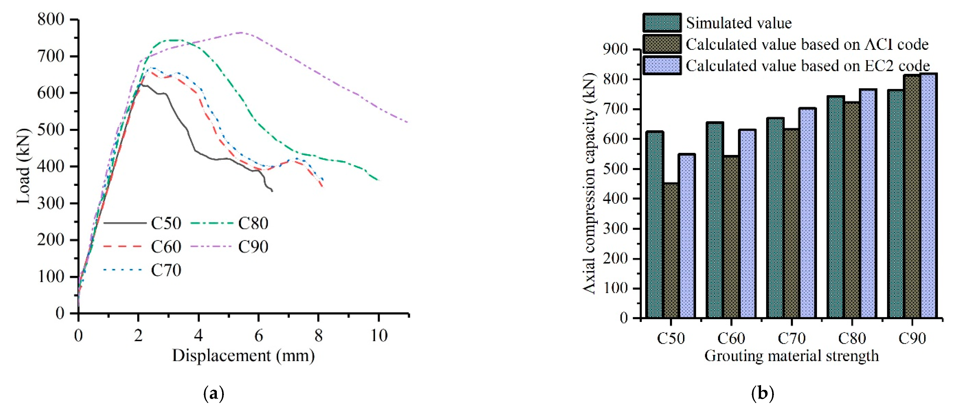
4.3.3. Strength of Grouting Material

Studies have shown that the grouting material strength has a certain influence on the axial compression capacity of the sleeve grouting connection [43]. The grouting material strength of specimen B3 was set as 50 MPa, 60 MPa, 70 MPa, 80 MPa, and 90 MPa. The axial compression capacity of the corresponding sleeve grouting connection was 624.2 kN, 655.0 kN, 669.7 kN, 743.2 kN, and 764.0 kN, respectively. Figure 16a shows the load–displacement curves of different grouting material strength models. When the grouting material strength is C50, the axial compression capacity of the model clearly decreases, as does the deformation capacity. The grouting material for the C60 and C70 model performance was similar. They were better than that of the grouting material strength for the C50 model. When the grouting material strength is C80 and C90, the model performance is better. With the increase in grouting material strength, the axial compression capacity of the sleeve grouting connection also increases. The model with a grouting material strength of C90 has the best deformation capacity. With the decrease in grouting material strength, the deformation capacity also decreased, but the regularity was not obvious.
As shown in Figure 16b, the calculated values of different grouting material strength models based on the ACI code and EC2 code were determined. Compared with the simulated values, all of the calculated values based on the ACI code were less than those based on the EC2 code and 9.6% smaller on average. The simulated values were 12.3% larger on average than those based on the ACI code. The simulated value is 0.66% larger than the calculated value of the European code. Compared with the calculated values in the EC2 code, the simulated values and the calculated values are relatively stable, which verifies the applicability of the simulation results and the calculated results of the axial compression capacity of the sleeve grouting connection for different grouting material strengths.

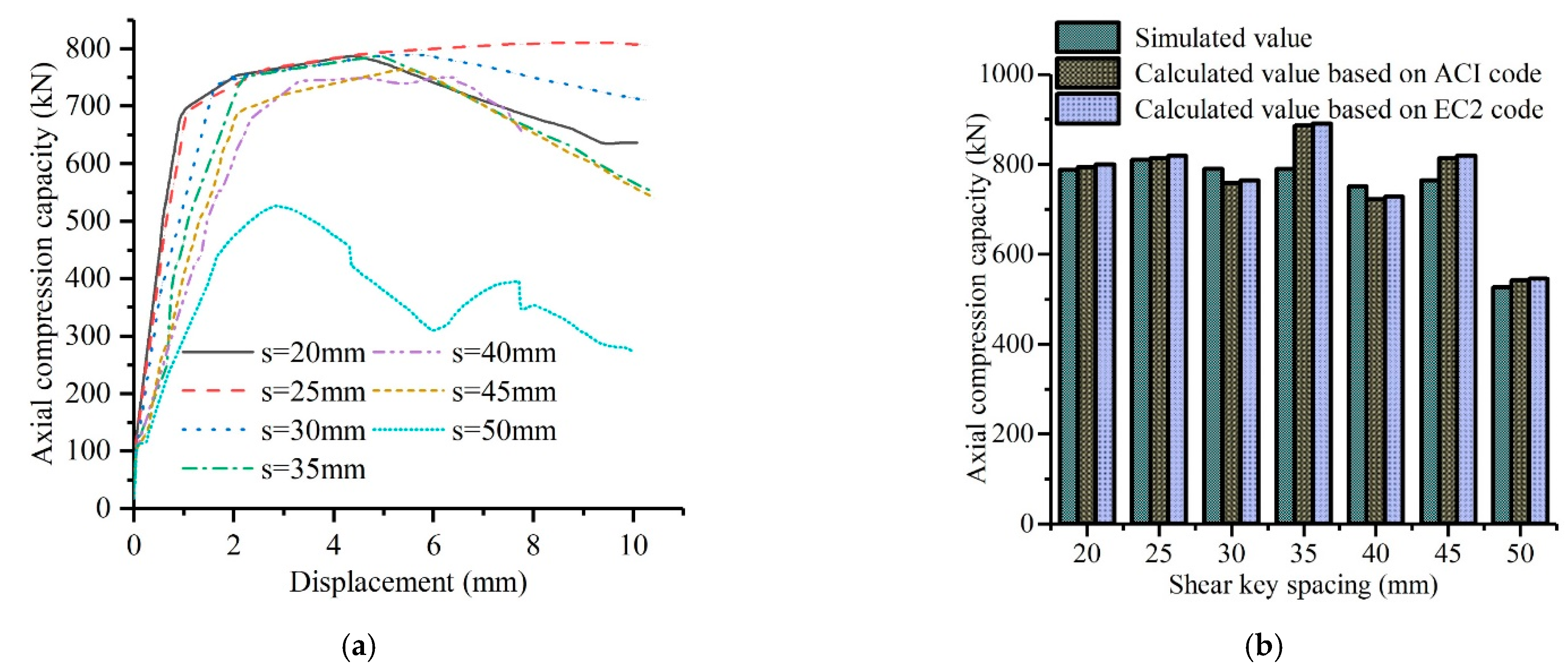
4.3.4. Shear Key Distance

The shear key distance has an impact on the failure mode of the sleeve grouting connection [44]. The shear key distance s of specimen B3 was changed to 20 mm, 25 mm, 30 mm, 35 mm, 40 mm, 45 mm, and 50 mm, and the shear key height h =2 mm remained unchanged, so the height-distance ratio h/s of the model was 0.044 to 0.1. Figure 17a shows the sleeve grouting connection model with different shear key distances. When s is equal to 50 mm, the height-distance ratio is 0.044, and both the axial compression capacity and deformation performance of the sleeve grouting connection decrease significantly. Compared with the 45 mm shear key distance model, the 50 mm shear key distance model bearing capacity was reduced by 31.2%. The displacement corresponding to the bearing capacity decreased by 47.0%. It showed that the performance of sleeve grouting connection decreases greatly when the height-distance ratio is less than 0.044. The main reason was that the interlock capacity between grouting material and shear key was weakened. Therefore, sleeve grouting connection with height-distance ratio less than 0.044 were not recommended. When s is equal to 20 mm to 45 mm, that is, h/s is equal to 0.044 to 0.1, the performance of the sleeve grouting connection is similar. These have high axial compression capacity and deformation capacity.
As shown in Figure 17b, the calculation of different shear key distances based on the ACI code and EC2 code was carried out and compared with the simulated values. The calculated values based on the ACI code were all less than those based on the EC2 code, 0.7% less on average. The simulated values were all less than the calculated values of the ACI code and EC2 code, 1.8% and 2.5% less on average, respectively. The overall simulated values and calculated values showed relatively stable characteristics, which verifies the applicability of the simulation results and calculated results for the axial compression capacity of the sleeve grouting connection with different shear key distances.

5. Conclusions

Through the introduction and application of strut-and-tie model theory, combined with numerical simulation and parameter extension analysis and based on experimental data, the axial compression capacity of the sleeve grouting connection of CFST columns is analyzed, and the following conclusions are put forward:
(1)
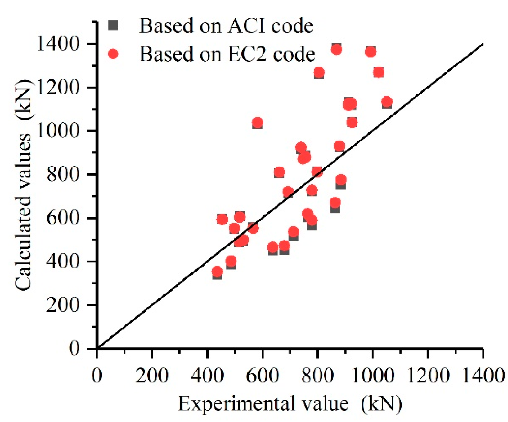
The calculated values of the strut-and-tie model based on the ACI code and EC2 code were close to the experimental values, among which the average ratio of the calculated-to-experimental values based on the ACI code was 1.07, and the average ratio of the calculated-to-experimental values based on the EC2 code was 1.09. This shows that the strut-and-tie model is applicable to the sleeve grouting connection of CFST columns.
(2)
High-precision finite element models of the sleeve grouting connection were established, and the existence of the struts in the sleeve grouting connection of the CFST column was further verified by the strain of the grouting material in the finite element model.
(3)
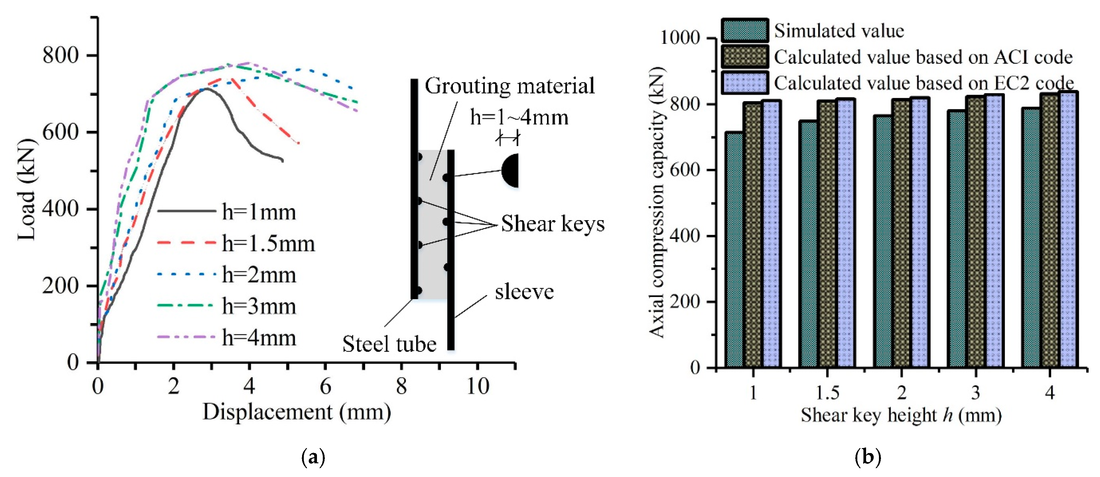
An increase in the shear key height can improve the axial compression capacity and ductility of the sleeve grouting connection. The suggested height range of the shear key is 2 to 3 mm, the model mechanics performance was better. When the shear key height was less than 2 mm, the axial compression capacity of the model was low, so that height was not recommended for use. When the shear key height was more than 3 mm, the axial compression capacity and ductility performance were not significantly increased.
(4)
It is suggested to adopt the shape of semicircular, rectangular vertical and trapezoidal shear keys, which can meet the requirements of sleeve grouting connections of CFST columns and have good mechanical performance. The rectangular vertical shear key showed the best load transmission performance, and the stress was not concentrated in the sleeve grouting connection, the rectangular transverse shear key showed the worst load transmission and were not recommended.
(5)
When the grouting material strength was C80 and C90, the axial compression capacity of the finite element model was better. With the increase in strength of the grouting material, the axial compression capacity of the sleeve grouting connection also increased, and the model showed the best deformation capacity when the grouting material strength was C90. It is reasonable to use grouting material strengths C50 to C90 for the sleeve grouting connection.
(6)
When the shear key distance is 50 mm, compared with the shear key distance of 45 mm, the bearing capacity was reduced by 31.2% and the displacement corresponding to the bearing capacity decreased by 47.0%, it showed that the axial compression capacity and deformation performance were significantly reduced, height-distance ratio less than 0.044 was not recommended. When the height-distance ratio is 0.044 to 0.1, the model performance of the sleeve grouting connection is close, and there is a higher axial compression capacity and deformation capacity, it is a reasonable height-distance ratio range.

Author Contributions

Conceptualization, W.C. and J.C. (Jianwei Chen); methodology, W.C.; software, W.C.; validation, J.C. (Jinglu Cao); formal analysis, W.T.; investigation, J.C. (Jianwei Chen); resources, J.C. (Jianwei Chen); data curation, W.C.; writing—original draft preparation, W.C.; writing—review and editing, W.C. All authors have read and agreed to the published version of the manuscript.

Funding

This research was funded by the National Natural Science Foundation of China (Project. 51678236) and the Natural Science Foundation of Hebei Province (Project. E2020209056 and Project. A2018209319).

Institutional Review Board Statement

Not applicable.

Informed Consent Statement

Not applicable.

Data Availability Statement

Not applicable.

Acknowledgments

The authors are very grateful to the National Natural Science Foundation of China (Project. 51678236) and the Natural Science Foundation of Hebei Province (Project. E2020209056 and Project. A2018209319). The opinions expressed in this research are the opinions of all the authors. The research was completed at North China University of Science and Technology.

Conflicts of Interest

The authors declare no conflict of interest.

References

  1. Han, L.H.; Wang, Z.B.; Xu, W.; Tao, Z. Behavior of concrete-encased CFST members under axial tension. J. Struct. Eng. 2016, 142, 1–12. [Google Scholar] [CrossRef]
  2. Wang, J.F.; Cai, A.M.; Liu, J. Analysis of offshore wind turbine foundation in China. In Proceedings of the 12th Annual Meeting of China Association for Science and Technology, Fuzhou, China, 1–13 November 2010; pp. 1–7. [Google Scholar]
  3. Liu, Y.; Guo, Z.X.; Jia, L.P.; Chen, Q.M. Experimental study on axial compression performance and design method of core steel tube reinforced concrete short columns. J. Build. Struct. 2015, 36, 135–142. [Google Scholar] [CrossRef]
  4. Liu, Y.; Wang, C.; Guo, Z.X.; Wang, P.Z.; Xu, Y.P. Axial compression performance and load bearing mechanism of prefabricated core steel tube reinforced concrete columns. J. Cent. S. Univ. (Sci. Technol.) 2019, 50, 3127–3136. [Google Scholar] [CrossRef]
  5. Chen, J.W.; Yan, W.S.; Su, Y.P.; Chen, H.B.; Feng, X.M. Experimental study on seismic performance of prefabricated shear wall with concrete filled steel tube. J. Build. Struct. 2015, 36, 176–184. [Google Scholar] [CrossRef]
  6. Chen, J.W.; Su, Y.P.; Gong, L.Y.; Yan, W.S.; Chen, H.B. Experimental study on seismic performance of prefabricated shear wall with concrete filled steel tube and opening. J. Build. Struct. 2016, 37, 251–260. [Google Scholar] [CrossRef]
  7. Nilson, H. Arthur, D. David, W.D. Charles. Design of Concrete Structures; McGraw-Hill Higher Education: New York, NY, USA, 2009; p. 332. [Google Scholar]
  8. Wu, L.W.; Su, Y.P.; Chen, H.B.; Yu, H.; Li, Y.P. Experimental study on axial mechanical performance of steel pipe-to-sleeve grouted connection. J. Build. Struct. 2019, 40, 191–199. [Google Scholar] [CrossRef]
  9. Wight, J.K.; MacGregor, J.G. Reinforced concrete: Mechanics and design. In Upper Saddle River; Pearson Education: New York, NY, USA, 2012; p. 879. [Google Scholar]
  10. Schlaich, J.; Schäfer, K.; Jennewein, M. Toward a consistent design of structural concrete. PCI J. 1987, 32, 74–150. [Google Scholar] [CrossRef]
  11. Schlaich, J.; Schäfer, K. Design and detailing of structural concrete using strut-and-tie models. Struct. Eng. 1991, 69, 113–125. [Google Scholar]
  12. Marti, P. Basic Tools of Reinforced Concrete Beam Design. ACI Struct. J. 1985, 82, 46–56. [Google Scholar] [CrossRef]
  13. Julio, A.; Ramirez, J.A. Strut-Tie Design of Pretensioned Concrete Members. ACI Struct. J. 1994, 94, 572–578. [Google Scholar] [CrossRef]
  14. ACI Committee 318. Building Code Requirements for Structural Concrete (ACI 318-14) and Commentary (318R-14); American Concrete Institute: Farmington Hills, MI, USA, 2014. [Google Scholar]
  15. European Committee for Standardization. Euro-Code 2, Design of Concrete Structures, Part 1-1: General Rules and Rules for Buildings, CEN, EN 1992-1-1; European Committee for Standardization: Brussels, Belgium, 2004. [Google Scholar]
  16. Adebar, P.; Zhou, Z. Bearing Strength of Compressive Struts Confined by Plain Concrete. ACI Struct. J. 1993, 90, 534–541. [Google Scholar] [CrossRef]
  17. Leu, L.J.; Huang, C.W.; Chen, C.S.; Asce, M.; Liao, Y.P. Strut-and-Tie design methodology for three-dimensional reinforced concrete structures. J. Struct. Eng. 2006, 132, 929–938. [Google Scholar] [CrossRef] [Green Version]
  18. Yun, Y.M.; Kim, B.H. Two-dimensional grid Strut -Tie model approach for structural concrete. J. Struct. Eng. 2008, 134, 1199–1214. [Google Scholar] [CrossRef]
  19. Wilson, H.R.; Yousefpour, H.; Brown, M.D.; Bayrak, O. Investigation of corbels designed according to strut-and-tie and empirical methods. ACI Struct. J. 2018, 115, 813–824. [Google Scholar] [CrossRef]
  20. Adebar, P.; Kuchma, D.; Collins, M.P. Strut-and-tie models for the design of pile caps: An experimental study. ACI Struct. J. 1990, 87, 81–92. [Google Scholar] [CrossRef]
  21. Adebar, P.; Zhou, L. Design of deep pile caps by strut-and-tie models. ACI Struct. J. 1996, 93, 437–448. [Google Scholar] [CrossRef]
  22. Guo, H.L. Investigation on Punching Behavior of Pile Cap under Column Reinforced by Section Steel Truss. ACI Struct. J. 2018, 115, 379–390. [Google Scholar] [CrossRef]
  23. Broms, C.E. Strut-and-Tie Model for Punching Failure of Column Footings and Pile Caps. ACI Struct. J. 2018, 115, 689–698. [Google Scholar] [CrossRef]
  24. Meléndez, C.; Sagaseta, J.; Sosa, P.M.; Rubio, L.P. Refined Three-Dimensional Strut-and-Tie Model for Analysis and Design of Four-Pile Caps. ACI Struct. J. 2019, 116, 15–29. [Google Scholar] [CrossRef]
  25. Matamoros, A.B.; Wong, K. Design of simply supported deep beams using strut and tie models. ACI Struct. J. 2003, 100, 704–712. [Google Scholar] [CrossRef]
  26. Brown, M.D.; Bayrak, O. Design of deep beams using strut-and-tie models—Part I: Evaluating US provisions. ACI Struct. J. 2008, 105, 395–404. [Google Scholar] [CrossRef]
  27. Brown, M.D.; Bayrak, O. Design of deep beams using strut-and-tie models—Part II: Design recommendations. ACI Struct. J. 2008, 105, 405–413. [Google Scholar] [CrossRef]
  28. Russo, G.; Venir, R.; Pauletta, M. Reinforced concrete deep beams-shear strength model and design formula. ACI Struct. J. 2005, 102, 429–437. [Google Scholar] [CrossRef]
  29. Hwang, S.J.; Lu, W.Y.; Lee, H.J. Shear strength prediction for deep beams. ACI Struct. J. 2000, 97, 367–376. [Google Scholar] [CrossRef]
  30. Yang, K.H.; Ashour, A.F. Strut-and-tie model based on crack band theory for deep beams. J. Struct. Eng. 2011, 137, 1030–1038. [Google Scholar] [CrossRef] [Green Version]
  31. Rezaei, N.; Klein, G.; Garber, D.B. Effect of Development and Geometry on Behavior of Concrete Deep Beams. ACI Struct. J. 2019, 116, 171–181. [Google Scholar] [CrossRef]
  32. Tuchscherer, R.G.; Birrcher, D.B.; Bayrak, O. Reducing Discrepancy between Deep Beam and Sectional Shear-Strength Predictions. ACI Struct. J. 2016, 113, 3–16. [Google Scholar] [CrossRef]
  33. Hwang, S.J.; Lee, H.J. Analytical model for predicting shear strengths of exterior reinforced concrete beam-column joints for seismic resistance. ACI Struct. J. 1999, 96, 846–857. [Google Scholar] [CrossRef]
  34. Hwang, S.J.; Lee, H.J. Analytical model for predicting shear strengths of interior reinforced concrete beam-column joints for seismic resistance. ACI Struct. J. 2000, 97, 35–44. [Google Scholar] [CrossRef]
  35. Wu, L.W. Experimental Study on Sleeve Grouted Connection Performance of Mine Concrete Filled Steel Tube; North China University of Science and Technology: Tangshan, China, 2018. [Google Scholar]
  36. Smith, B.L.; Tebbett, I.E. New Data on Grouted Connections with Large Grout Dimensions; Society of Petroleum Engineers: Houston, TX, USA, 1989; pp. 291–298. [Google Scholar] [CrossRef]
  37. Wang, G.Q. The Axial Bearing Capacity of Large-Diameter Grouted Connections for Offshore Wind Turbines; Zhejiang University: Hangzhou, China, 2017. [Google Scholar]
  38. Gong, J.X.; Wei, W.W.; Hu, J.H. China, American and European Concrete Structure Design; China Building Industry Press: Beijing, China, 2003. [Google Scholar]
  39. Yu, Z.W.; Ding, F.X. Unified calculation method of compressive mechanical properties of concrete. J. Build. Struct. 2003, 24, 41–46. [Google Scholar]
  40. Ding, F.X.; Yu, Z.W. Unified calculation method of tensile mechanical properties of concrete. J. HUST 2004, 21, 29–34. [Google Scholar]
  41. Merxhani, A.; Jensen, J.F.; Caetano, J.; Christiansen, C.K. Critical review of early age cycling effects on the capacity of pile to sleeve grouted conncetions as treated in ISO 19902. In Proceedings of the ASME 2019 38th International Conference on Ocean, Offshore and Arctic Engineering OMAE2019, Glasgow, UK, 9–14 June 2019. [Google Scholar]
  42. Teng, L.R. Research of Grouted Connection to Improve the Axial Bearing Capacity in Offshore Wind; Da Lian University of Technology: Dalian, China, 2014. [Google Scholar]
  43. Lamport, W.B.; Jirsa, J.O.; Yura, J.O. Strength and behavior of grouted pile-sleeve conncetions. J. Struct. Eng. 1991, 117, 2477–2498. [Google Scholar] [CrossRef]
  44. Wang, Z.; Jiang, S.C.; Zhang, J. Structural performance of prestressed grouted pile-to-sleeve connection. Prog. Steel Build. Struct. 2010, 12, 11–18. [Google Scholar] [CrossRef] [Green Version]
Figure 1. Sleeve grouting connection of the concrete-filled steel tube column.
Jmse 10 00629 g001
Figure 2. Discontinuity region of load or geometry: (a) load discontinuous region; (b) load discontinuous region.
Jmse 10 00629 g002
Figure 3. Model of sleeve grouting connection: (a) strut-and-tie model; (b) simplified mechanical model.
Jmse 10 00629 g003
Figure 4. Details of the grouted sleeve connection.
Jmse 10 00629 g004
Figure 5. Concrete strut under compressive stress.
Jmse 10 00629 g005
Figure 6. Layout of shear keys in sleeve grouting connection: (a) 60a; (b) B3.
Jmse 10 00629 g006
Figure 7. Sleeve grouting connection of equal height shear keys.
Jmse 10 00629 g007
Figure 8. The load of the extended node region.
Jmse 10 00629 g008
Figure 9. Sleeve grouting connection of the staggered arrangement of shear keys.
Jmse 10 00629 g009
Figure 10. Comparison of the calculated and experimental values based on the ACI code and EC2 code.
Jmse 10 00629 g010
Figure 11. Finite element analysis of 60a: (a) model of 60a; (b) strain in the sleeve grouting connection; (c) Load–Displacement curve.
Jmse 10 00629 g011
Figure 12. Finite element analysis of B3: (a) model of B3; (b) strain in the sleeve grouting connection; (c) load–displacement curve.
Jmse 10 00629 g012
Figure 13. Comparison of simulated and experimental values.
Jmse 10 00629 g013
Figure 14. Different shear key heights: (a) comparison of load–displacement curves for different shear key heights; (b) comparison of calculated and simulated values of different shear key heights.
Jmse 10 00629 g014
Figure 15. Different shear key shapes: (a) grouting strain of different shear key shapes; (b) comparison of load–displacement curves of different shear key shapes.
Jmse 10 00629 g015
Figure 16. Different grouting strengths: (a) comparison of load–displacement curves of different grouting strengths; (b) comparison of the calculated and simulated values of different grouting strengths.
Jmse 10 00629 g016
Figure 17. Different shear key distances: (a) comparison of load–displacement curves of different shear key distances; (b) comparison of calculated and simulated values of different shear key distances.
Jmse 10 00629 g017
Table 1. Basic information on the specimens.
SpecimenDg/mmL/mms/mmh/mmPu/kN
60a10260192.5487.5
60b10260192.5638.4
60c10260192.5436.8
80a10280192.5713.1
80b10280192.5765.0
80c10280192.5680.8
100a102100192.5863.3
100b102100192.5884.5
100c102100192.5779.1
A160.3150352517.3
A260.3150402532.0
A360.3150452566.7
A460.3150351455.1
A560.3150401514.7
A660.3150451499.1
B188.9150352757.2
B288.9150402779.8
B388.9150452799.5
B488.9150351747.4
B588.9150401693.3
B688.9150451662.1
C1114.3150352912.5
C2114.3150402878.5
C3114.3150452925.0
C4114.3150351912.4
C5114.3150401741.0
C6114.3150451583.0
D1139.7150352869.9
D2139.71504021050.8
D3139.71504521021.6
D4139.7150351993.1
D5139.7150401923.0
D6139.7150451805.0
Table 2. Comparison of calculated values and experimental values based on ACI code.
SpecimenCalculated/ExperimentalSpecimenCalculated/Experimental
UC60a0.79B31.02
UC60b0.71B41.17
UC60c0.78B51.03
UC80a0.72B61.21
UC80b0.79C11.24
UC80c0.66C21.05
UC100a0.74C31.12
UC100b0.85C41.23
UC100c0.73C51.24
A11.17C61.77
A20.93D11.59
A30.98D21.07
A41.31D31.24
A50.95D41.38
A61.10D51.21
B11.17D61.56
B20.93--
Table 3. Comparison of calculated values and experimental values based on the EC2 code.
SpecimenCalculated/ExperimentalSpecimenCalculated/Experimental
UC60a0.82B31.02
UC60b0.73B41.16
UC60c0.81B51.04
UC80a0.75B61.22
UC80b0.81C11.23
UC80c0.69C21.06
UC100a0.78C31.13
UC100b0.87C41.23
UC100c0.76C51.25
A11.17C61.78
A20.94D11.58
A30.99D21.08
A41.30D31.25
A50.95D41.37
A61.11D51.22
B11.16D61.57
B20.93--
Publisher’s Note: MDPI stays neutral with regard to jurisdictional claims in published maps and institutional affiliations.

