
Modelling Open Ocean Aquaculture Structures Using CFD and a Simulation-Based Screen Force Model


Abstract
:1. Introduction
2. Numerical Model
2.1. Fluid Dynamics Solver
2.2. Simulation-Based Screen Force Model
3. Validation
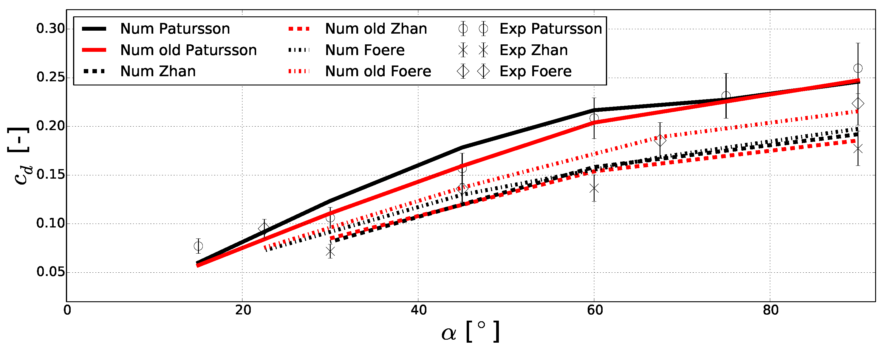
3.1. Current Cases
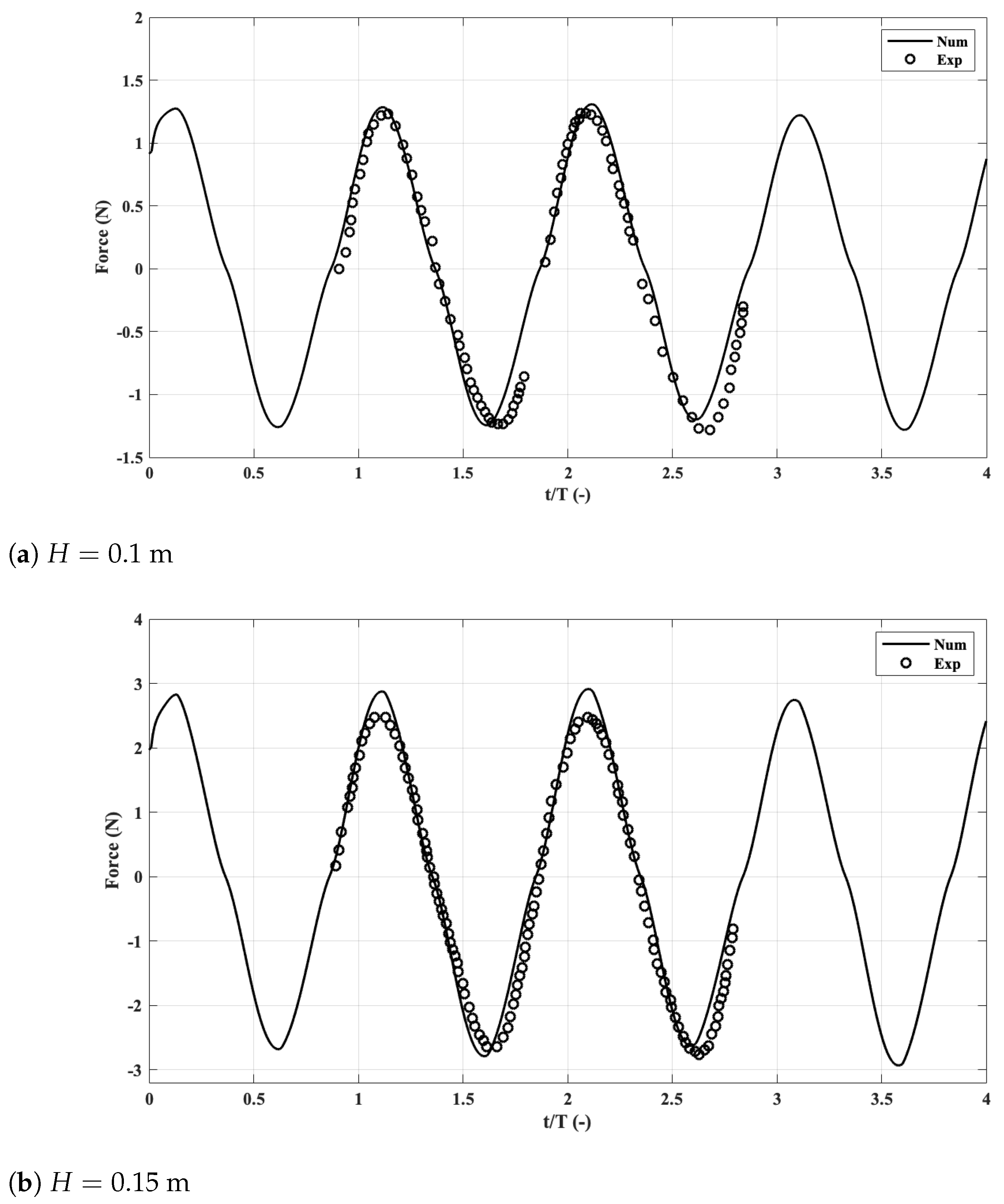
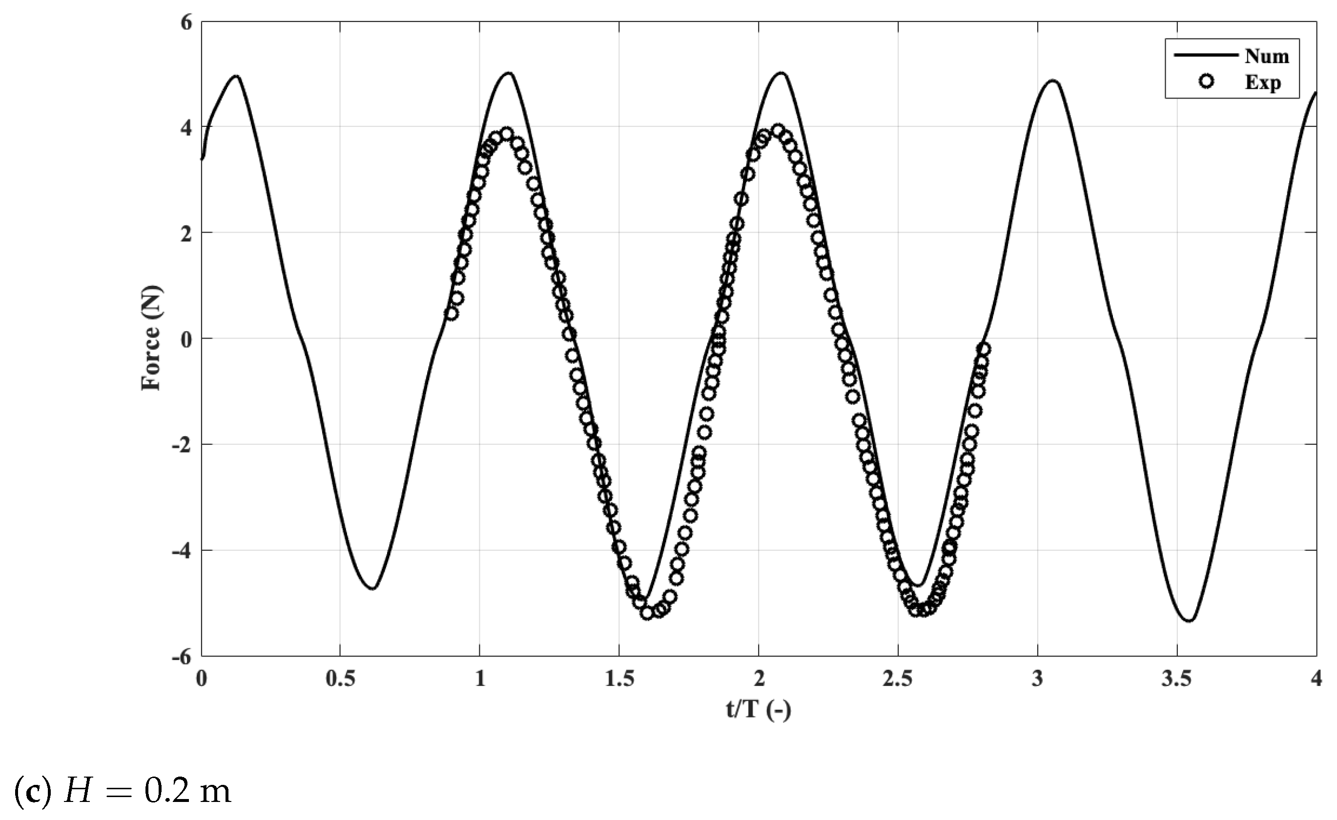
3.2. Wave Cases
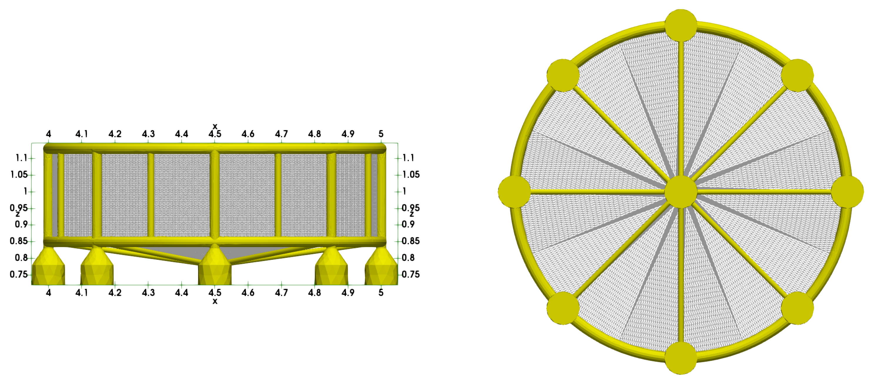
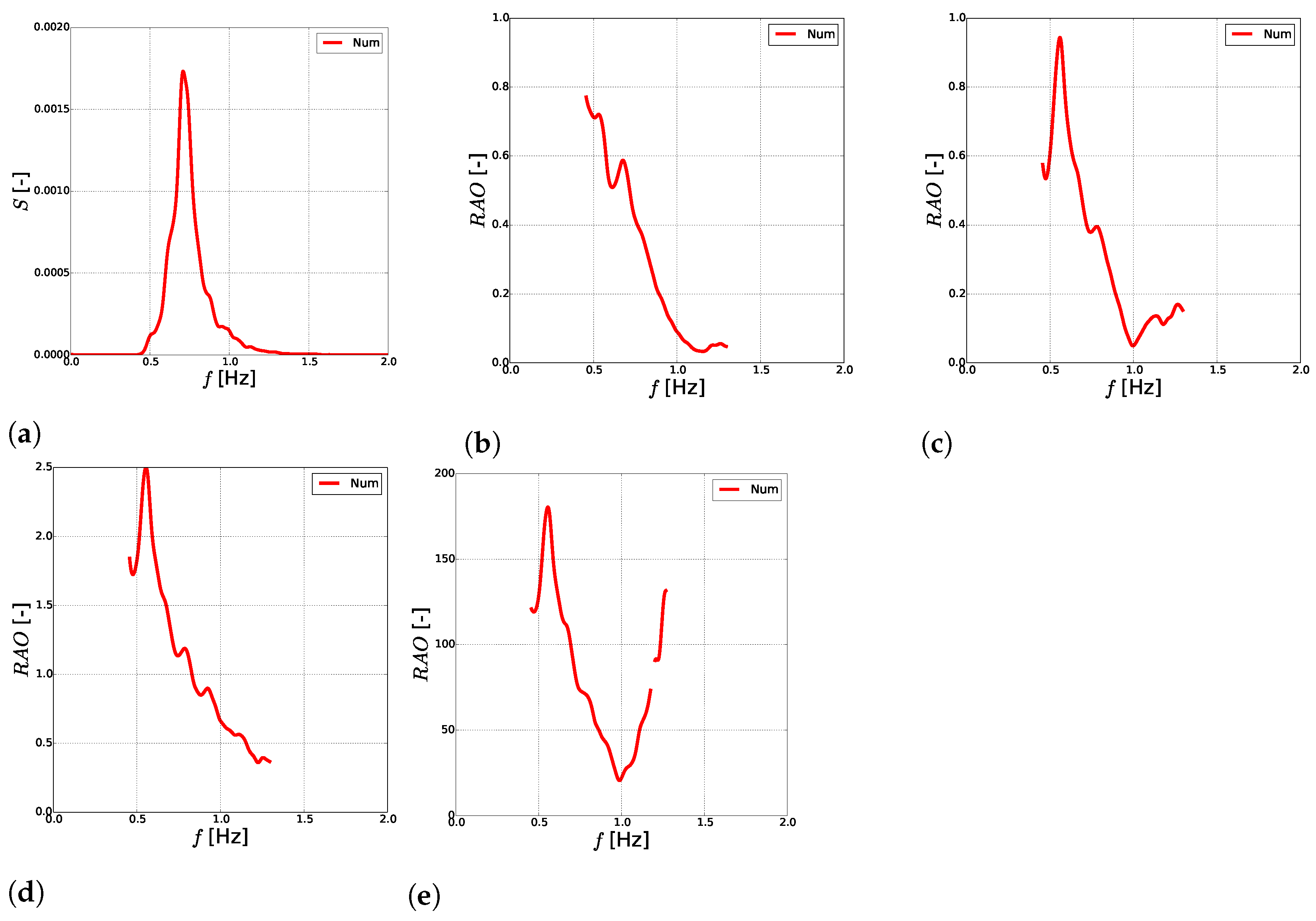
4. Application to the Motion of a Semi-Submersible OOA Structure in Irregular Waves
5. Conclusions
Author Contributions
Funding
Data Availability Statement
Conflicts of Interest
References
- Zhao, Y.P.; Li, Y.C.; Dong, G.H.; Teng, F.K.; Wu, H. An experimental and numerical study of hydrodynamic characteristics of submerged flexible plane nets in waves. Aquac. Eng. 2008, 38, 16–25. [Google Scholar] [CrossRef]
- Kristiansen, T.; Faltinsen, O.M. Experimental and numerical study of an aquaculture net cage with floater in waves and current. J. Fluids Struct. 2015, 54, 1–26. [Google Scholar] [CrossRef] [Green Version]
- Shen, Y.; Greco, M.; Faltinsen, O.; Nygaard, I. Numerical and experimental investigations on mooring loads of a marine fish farm in waves and current. J. Fluids Struct. 2018, 79, 115–136. [Google Scholar] [CrossRef]
- Fredriksson, D.; Swift, M.; Irish, J.; Tsukrov, I.; Celikkol, B. Fish cage and mooring system dynamics using physical and numerical models with field measurements. Aquac. Eng. 2003, 27, 117–146. [Google Scholar] [CrossRef]
- Chen, H.; Christensen, E. Simulating the hydrodynamic response of a floater net system in current and waves. J. Fluids Struct. 2018, 79, 50–75. [Google Scholar] [CrossRef] [Green Version]
- Bi, C.W.; Zhao, Y.P.; Dong, G.H.; Xu, T.J.; Gui, F.K. Numerical simulation of the interaction between flow and flexible nets. J. Fluids Struct. 2014, 45, 180–201. [Google Scholar] [CrossRef]
- Patursson, Ø.; Swift, M.R.; Tsukrov, I.; Simonsen, K.; Baldwin, K.; Fredriksson, D.; Celikkol, B. Development of a porous media model with application to flow through and around a net panel. Ocean. Eng. 2010, 37, 314–324. [Google Scholar] [CrossRef]
- Martin, T.; Kamath, A.; Bihs, H. A Lagrangian approach for the coupled simulation of fixed net structures in a Eulerian fluid model. J. Fluids Struct. 2020, 94, 102962. [Google Scholar] [CrossRef]
- Martin, T.; Bihs, H. A non-linear implicit approach for modelling the dynamics of porous tensile structures interacting with fluids. J. Fluids Struct. 2021, 100, 103168. [Google Scholar] [CrossRef]
- Martin, T.; Tsarau, A.; Bihs, H. A numerical framework for modelling the dynamics of open ocean aquaculture structures in viscous fluids. Appl. Ocean. Res. 2021, 106, 102410. [Google Scholar] [CrossRef]
- Morison, J.; O’Brien, M.; Johnson, J.; Schaaf, S. The force exerted by surface waves on piles. Pet. Trans. Am. Inst. Min. Eng. 1950, 186, 149–154. [Google Scholar] [CrossRef]
- Kawakami, T. Development of mechanical studies of fishing gear. In Modern Fishing Gear of the World; Fishing News (Books): London, UK, 1959; pp. 175–184. [Google Scholar]
- Fridman, A.; Danilov, Y. Ob osobennostyah soprotivleniya rybolovnoi seti. Rybolov. Hozyajstvo 1967, 6, 38–40. (In Russian) [Google Scholar]
- Løland, G. Current Forces on and Flow through Fish Farms. Ph.D. Thesis, NTNU, Trondheim, Norway, 1991. [Google Scholar]
- Kristiansen, T.; Faltinsen, O.M. Modelling of current loads on aquaculture net cages. J. Fluids Struct. 2012, 34, 218–235. [Google Scholar] [CrossRef]
- Wang, G.; Martin, T.; Huang, L.; Bihs, H. An improved screen force model based on CFD simulations of the hydrodynamic loads on knotless net panels. Appl. Ocean. Res. 2022, 118, 102965. [Google Scholar] [CrossRef]
- Bihs, H.; Kamath, A.; Alagan Chella, M.; Aggarwal, A.; Arntsen, Ø.A. A new level set numerical wave tank with improved density interpolation for complex wave hydrodynamics. Comput. Fluids 2016, 140, 191–208. [Google Scholar] [CrossRef]
- Martin, T.; Kamath, A.; Bihs, H. Accurate modeling of the interaction of constrained floating structures and complex free surfaces using a new quasistatic mooring model. Int. J. Numer. Methods Fluids 2021, 93, 504–526. [Google Scholar] [CrossRef]
- Sussman, M.; Smereka, P.; Osher, S. A level set approach for computing solutions to incompressible two-phase flow. J. Comput. Phys. 1994, 114, 146–159. [Google Scholar] [CrossRef]
- Timmermans, L.; Minev, P.; Van De Vosse, F. An approximate projection scheme for incompressible flow using spectral elements. Int. J. Numer. Methods Fluid 1996, 22, 673–688. [Google Scholar] [CrossRef]
- Shu, C.; Osher, S. Efficient implementation of essentially non-oscillatory shock-capturing schemes. J. Comput. Phys. 1988, 77, 439–471. [Google Scholar] [CrossRef] [Green Version]
- Jiang, G.; Shu, C. Efficient implementation of weighted ENO schemes. J. Comput. Phys. 1996, 126, 202–228. [Google Scholar] [CrossRef] [Green Version]
- van der Vorst, H. BiCGStab: A fast and smoothly converging variant of Bi-CG for the solution of nonsymmetric linear systems. SIAM J. Sci. Comput. 1992, 13, 631–644. [Google Scholar] [CrossRef]
- Føre, H.; Endresen, P.; Norvik, C.; Lader, P. Loads on net panels with different solidities. In Proceedings of the ASME 2020 39th International Conference on Ocean, Offshore and Arctic Engineering, Virtual Conference, Online, 3 August 2020–7 August 2020. [Google Scholar]
- Zhan, J.; Jia, X.; Li, Y.; Sun, M.; Guo, G.; Hu, Y. Analytical and experimental investigation of drag on nets of fish cages. Aquac. Eng. 2006, 35, 91–101. [Google Scholar] [CrossRef]
- Zhao, Y.; Guan, C.; Bi, C.; Liu, H.; Cui, Y. Experimental Investigations on Hydrodynamic Responses of a Semi-Submersible Offshore Fish Farm in Waves. J. Mar. Sci. Eng. 2019, 7, 238. [Google Scholar] [CrossRef] [Green Version]


Publisher’s Note: MDPI stays neutral with regard to jurisdictional claims in published maps and institutional affiliations. |
© 2022 by the authors. Licensee MDPI, Basel, Switzerland. This article is an open access article distributed under the terms and conditions of the Creative Commons Attribution (CC BY) license (https://creativecommons.org/licenses/by/4.0/).
Share and Cite
Martin, T.; Kamath, A.; Wang, G.; Bihs, H. Modelling Open Ocean Aquaculture Structures Using CFD and a Simulation-Based Screen Force Model. J. Mar. Sci. Eng. 2022, 10, 332. https://doi.org/10.3390/jmse10030332
Martin T, Kamath A, Wang G, Bihs H. Modelling Open Ocean Aquaculture Structures Using CFD and a Simulation-Based Screen Force Model. Journal of Marine Science and Engineering. 2022; 10(3):332. https://doi.org/10.3390/jmse10030332
Chicago/Turabian StyleMartin, Tobias, Arun Kamath, Gang Wang, and Hans Bihs. 2022. "Modelling Open Ocean Aquaculture Structures Using CFD and a Simulation-Based Screen Force Model" Journal of Marine Science and Engineering 10, no. 3: 332. https://doi.org/10.3390/jmse10030332
APA StyleMartin, T., Kamath, A., Wang, G., & Bihs, H. (2022). Modelling Open Ocean Aquaculture Structures Using CFD and a Simulation-Based Screen Force Model. Journal of Marine Science and Engineering, 10(3), 332. https://doi.org/10.3390/jmse10030332