Article

Buckling of a Composite Cylindrical Shell with Cantilever-like Boundary Conditions under Hydrostatic Pressure

1
School of Marine Science and Technology, Northwestern Polytechnical University, Xi’an 710072, China
2
Key Laboratory for Unmanned Underwater Vehicle, Northwestern Polytechnical University, Xi’an 710072, China
3
Structural Ceramics and Composites Engineering Research Center, Shanghai Institute of Ceramics, Chinese Academy of Sciences, Shanghai 200050, China
*
Author to whom correspondence should be addressed.
J. Mar. Sci. Eng. 2022, 10(2), 126; https://doi.org/10.3390/jmse10020126
Submission received: 3 December 2021 / Revised: 8 January 2022 / Accepted: 10 January 2022 / Published: 19 January 2022
(This article belongs to the Special Issue Frontiers in Deep-Sea Equipment and Technology)

Abstract

:
In this study, an analytical solution for the buckling of a composite cylindrical shell subjected to hydrostatic pressure is proposed. The boundary conditions of the composite cylindrical shell are cantilever-like, with one end fixed and the other end connected to a rigid disk. The differential equations are solved using the Galerkin method. The axial displacement of the shell is approximated by the first mode shape of the transverse vibration of the clamped sliding beam. The circumferential displacement and deflection are approximated by the first derivation of the beam function. Based on this solution, an analytical formula enabling prediction of the critical buckling pressure and buckling mode of composite orthotropic cylindrical shells is derived. A finite element analysis and external hydrostatic pressure test are conducted to verify the proposed approach. The efficiency and accuracy of the analytical solution in predicting the critical buckling pressure and buckling mode are demonstrated.

1. Introduction

Composite materials have been widely used in civil, aeronautical and marine engineering fields due to their excellent mechanical properties, such as their high specific strength and stiffness [1]. In recent years, composite cylindrical shells have been increasingly applied in underwater vehicles to withstand hydrostatic pressure and improve the buoyancy-to-weight ratio [2].
Buckling [3,4,5,6,7,8,9] is a major failure form for thin-walled composite cylindrical shells. Hajlaoui studied the buckling and postbuckling analysis of composite shell structures using modified first shear deformation theory [3,4], enhanced solid-shell elements and transverse shear correction [5,6]. Some researchers have investigated the buckling of composite cylindrical shells subjected to hydrostatic pressure using experimental methods. Carvelli [7] conducted off-shore testing and observed considerable deformation and the collapse instant of a glass-fiber-reinforced polymer cylindrical shell. Denardo [10] and Gupta [11] carried out experiments to reveal the mechanisms of shock-initiated buckling of a composite cylindrical shell. Hur [12] investigated the postbuckling of composite cylinders under external hydrostatic pressure. Ross [13] studied the buckling of carbon–glass composite tubes under uniform external hydrostatic pressure. Moon [14] researched the buckling of filament winding composite cylinders with three winding sequences of [±30/90]FW, [±45/90]FW and [±60/90]FW under external hydrostatic pressure for underwater vehicle applications. Tang [15] studied the failure mode of circumferentially corrugated cylinders under external hydrostatic pressure. In the abovementioned studies, the critical buckling pressure was determined by the instantaneous pressure when the composite cylindrical shell collapsed. An external hydrostatic test helped scholars understand the ultimate bearing capacity of the shell structure. In recent years, analytical and numerical methods have been widely used to predict the buckling of cylindrical shells subjected to hydrostatic pressure. Some researchers have studied the buckling strength of cylindrical shells, focusing on the influence of winding patterns [16] and imperfection [17,18,19]. Li [20] evaluated the critical buckling pressure of pipes under hydrostatic pressure by considering geometrical imperfections. Almeida [21] predicted the buckling load of composite tubes under external pressure, whereby cylindrical shells with various winding patterns were tested. Lopatin derived analytical solutions for the critical buckling pressure of composite cylindrical shells subjected to external pressure. One was for the buckling of cylindrical shells with rigid end disks under hydrostatic pressure [22], while the other was for a cylindrical shell with fully clamped ends loaded by lateral pressure [23]. Matos [24] presented a closed-form solution for the critical buckling pressure of underwater composite cylinders with arbitrary configurations. In addition, several studies [25,26,27,28,29,30] have been conducted on optimization design to enhance the buckling resistance of cylindrical shells. Messager [31] and Shen [32] used an optimization algorithm coupled with an analytical model to maximize the stability limits of thin-walled underwater composite cylindrical vessels. Lee [33] optimized the design load of a composite sandwich cylinder under external hydrostatic pressure by applying a micro genetic algorithm and finite element analysis. In the above studies, the optimization objective was achieved mostly by solving differential equations using the analytical method or finite element method. From reviewing the above studies, it was found that the buckling deformation behavior has rarely been reported. In one study, a cylindrical shell subjected to hydrostatic pressure was closed at both ends, which meant the deformation phenomenon was hard to observe. This motivated the authors to propose effective methods to study the buckling behavior of cylindrical shells. To this end, a new kind of cantilever-like boundary condition is constructed for composite cylindrical shells under hydrostatic pressure in this work. The buckling deformation behavior is studied using experimental and analytical methods.
This work is from our series of studies, including [34], where the buckling of composite cylindrical shells with clamped ends under hydrostatic pressure was investigated. In the present investigation, an analytical solution for the buckling of composite cylindrical shells under hydrostatic pressure with one fixed end and one cantilever-like end is proposed. The first mode shape of the transverse vibration of the clamped sliding beam function and its first derivation are chosen to approximate the axial displacement and circumferential displacement of the shell, respectively. The Galerkin method is used to solve the differential equations. Furthermore, analytical examples are conducted to predict the buckling pressure and buckling mode of the composite cylindrical shell. An external hydrostatic pressure test is carried out and the buckling deformation shape is observed. The deviations between the analytical and experimental results are discussed. Eventually, the efficiency and accuracy of the proposed approach are validated.

2. Linearized Buckling Analytical Solution

The geometry of the composite cylindrical shell with cantilever-like boundary conditions is shown in Figure 1. The length of the shell is L, including the left fixed boundary and the right rigid end disk. The radius of the middle surface is R. The composite cylindrical shell is subjected to uniform external hydrostatic pressure p, which can result in shell buckling.
Here, linearized buckling equations are used for the orthotropic cylindrical shell [35]:
N x x + N x y y = 0 N x y x + N y y + M x y R x + M y R y = 0 2 M x x 2 + 2 2 M x y x y + 2 M y y 2 N y R + N x 0 2 ω x 2 + N x y 0 ( 2 2 ω x y υ R x ) + N y 0 ( 2 ω y 2 υ R y ) = 0
in which Nx, Ny and Nxy are the longitudinal, circumferential and shear membrane force resultants, respectively; Mx, My and Mxy are bending and twisting moments, respectively. The constitutive equations are expressed as [36]:
N x = A 11 ε x 0 + A 12 ε y 0 ,   N y = A 12 ε x 0 + A 22 ε y 0 ,   N x y = A 66 ε x y 0
M x = D 11 k x + D 12 k y ,   M y = D 12 k x + D 22 k y ,   M x y = D 66 k x y
in which Aij and Dij (i, j = 1, 2, 6) are the extensional and bending stiffness, respectively; ε x 0 , ε y 0 and ε x y 0 are longitudinal, circumferential and in-plane shear strains, respectively; kx, ky and kxy are bending and twisting deformation, respectively. According to thin shell theory [31], the geometric equations are:
ε x 0 = u x ,   ε y 0 = υ y + ω R ,   ε x y 0 = u y + υ x
κ x = 2 u x 2 ,   κ y = υ R y 2 ω y 2 ,   κ x y = υ R x 2 2 ω x y
in which u and υ are the in-plane displacements along axial and circumferential directions, respectively; ω is the deflection of the middle surface.
Equations (1)~(5) should be supplemented with boundary conditions at two ends. For the fixed end, it is assumed that the axial displacement of the edge of the cylindrical shell is zero and takes its minimum value. This can be achieved by:
u x | x = L = 0   and   N x | x = L = 0
For the right end, this is connected to the rigid disk, allowing axial displacement with its maximum value. This boundary condition yields:
ε x 0 = u x ,   ε y 0 = υ y + ω R ,   ε x y 0 = u y + υ x
As for the circumferential displacement υ and deflection ω, they should satisfy the following conditions according to the buckling mode of the cylindrical shell shown in Figure 2:
υ | x = 0 , L = 0 ,   ω | x = 0 , L = 0
Taking the prebuckling state of the shell for the membrane, the resultants N x 0 , N y 0 and N x y 0 in Equation (1) are determined:
N x 0 = p R / 2 ,   N y 0 = p R ,   N x y 0 = 0
Substituting the constitutive equations, geometric equations and the resultants of the prebuckling state into Equation (1), the following presentations are obtained in terms of displacements u, υ and ω:
A 11 2 u x 2 + A 12 ( 2 υ x y + ω R x ) + A 66 ( 2 u y 2 + 2 υ x y ) = 0 A 66 ( 2 u x y + 2 υ x 2 ) + A 12 2 u x y + A 22 ( 2 υ y 2 + ω R y ) + 1 R { D 66 ( 2 υ R x 2 2 3 ω x 2 y ) D 12 3 ω x 2 y + D 22 ( 2 υ R y 2 3 ω y 3 ) } = 0 D 11 4 ω x 4 + D 12 ( 3 υ R x 2 y 4 ω x 2 y 2 ) + D 66 ( 2 3 υ R x 2 y 4 4 ω x 2 y 2 ) D 12 4 ω x 2 y 2 + D 22 ( 3 υ R y 3 4 ω y 4 ) 1 R { A 12 u x + A 22 ( υ y + ω R ) } p R 2 2 ω x 2 p R ( 2 ω y 2 υ R y ) = 0
Considering the buckling mode of the cylindrical shell shown in Figure 2, u, υ and ω are periodic functions of the circumferential coordinate y, which can be represented as follows:
u = U ( x ) cos n y R ,   υ = V ( x ) sin n y R ,   ω = W ( x ) cos n y R
in which n is the number of circumferential waves in the buckling mode of the shell, while the functions U(x), V(x) and W(x) are determined by the buckling shape of the shell along its axial direction. Substituting Equation (11) into Equation (10), the following system of homogeneous ordinary differential equations is obtained:
A 11 2 U ( x ) x 2 A 66 n 2 R 2 U ( x ) + ( A 12 + A 66 ) n R V ( x ) x + A 12 1 R W ( x ) x = 0 ( A 66 A 12 ) n R U ( x ) x + ( A 22 D 22 R 2 ) n 2 R 2 V ( x ) + ( A 66 + D 66 R 2 ) 2 V ( x ) x 2 + ( A 22 n R 2 D 22 n 3 R 4 ) W ( x ) + ( 2 D 66 + D 12 ) n R 2 2 W ( x ) x 2 = 0 A 12 1 R U ( x ) x + ( A 22 n R 2 D 22 n 3 R 4 + p n R ) V ( x ) + ( D 12 + 2 D 66 ) n R 2 2 V ( x ) x 2 + ( A 22 R 2 D 22 n 4 R 4 + p n 2 R ) W ( x ) + ( 2 D 12 n 2 R 2 + 4 D 66 n 2 R 2 p R 2 ) 2 W ( x ) x 2 D 11 4 W ( x ) x 4 = 0
The Galerkin method is used to solve the differential equations to find the instability pressure of a cylindrical shell subjected to hydrostatic pressure. To utilize this method, an approximation function should satisfy the boundary conditions. Considering the characteristics of axial displacement, the function U(x) can be approximated by the first mode shape of transverse vibration of uniform single-span beams with clamped sliding boundary conditions.
U ( x ) = U c o n s F ( x )
in which the unknown constant, F(x), is the clamped sliding beam function, which is determined by [37]:
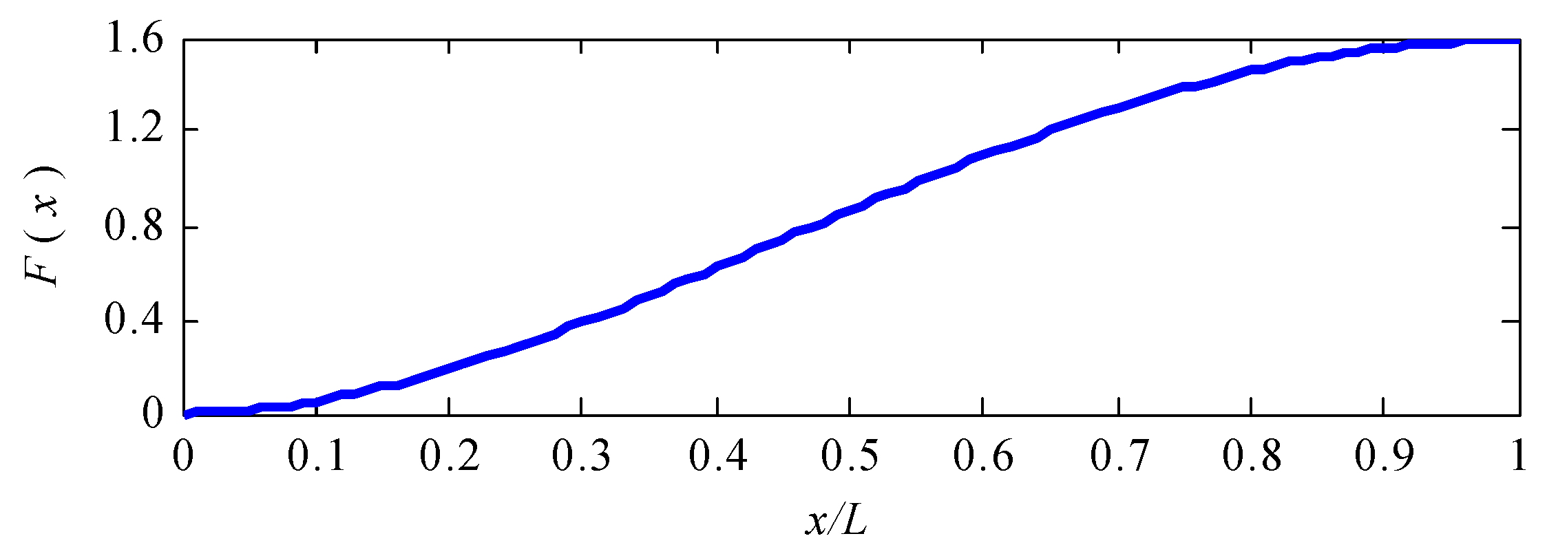
F ( x ) = cosh λ x L cos λ x L σ ( sinh λ x L sin λ x L )
in which λ = 2.36502037, σ = 0.982502207. The graph of this function is shown in Figure 3.
Following from Equations (11), (14) and (15) are obtained. Thus, the boundary conditions of axial displacement shown in Equations (6) and (7) are satisfied.
U ( x ) = U c o n s F ( x )
Considering the constitutive equations in Equation (2) and geometric equations in Equation (4), the boundary conditions of the expression Nx in Equations (6) and (7) are transformed into the following form:
N x | x = 0 , L = A 11 U ( x ) x cos n y R + A 12 ( n R V ( x ) + 1 R W ( x ) ) cos n y R = 0
Substituting Equations (13) and (14) into Equation (16), the boundary conditions are reduced to:
N x | x = 0 , L = A 12 ( n R V ( x ) + 1 R W ( x ) ) cos n y R = 0
As the buckling mode of the shell is characterized by a wave in the longitudinal direction, the circumferential displacement υ and deflection ω can be approximated by the first derivation of the clamped sliding beam function. V(x) and W(x) can be selected in the following form:
V ( x ) = V c o n s F ( x ) x
W ( x ) = W c o n s F ( x ) x
where V c o n s  and W c o n s are unknown constants, while the first derivation of F(x) is given by:
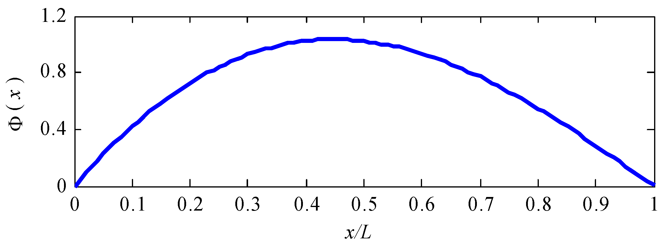
F ( x ) x = λ L Φ ( x )
where:
Φ ( x ) = sinh λ x L + sin λ x L σ ( cosh λ x L cos λ x L )
A graph of the approximated function is shown in Figure 4. It can be seen that the boundary conditions given in Equations (8) and (17) are satisfied. Hence, it is verified that the three unknown functions V(x), W(x) and U(x) can be approximated by Equations (21) and (14), respectively.
According to the Galerkin procedure, substituting Equations (13), (18) and (19) into Equation (12), the following residuals are obtained:
R x = ( A 11 2 F ( x ) x 2 A 66 n 2 R 2 F ( x ) ) U c o n s + ( A 12 + A 66 ) n R 2 F ( x ) x 2 V c o n s + A 12 R 2 F ( x ) x 2 W c o n s R y = ( A 12 A 66 ) n R F ( x ) x U c o n s + { ( A 22 n 2 R 2 D 22 n 2 R 4 ) F ( x ) x + ( A 66 + D 66 R 2 ) 3 F ( x ) x 3 } V c o n s + { ( A 22 n R 2 D 22 n 3 R 4 ) F ( x ) x + ( D 12 n R 2 + 2 D 66 n R 2 ) 3 F ( x ) x 3 } W c o n s R z = A 12 R F ( x ) x U c o n s + { ( p n R A 22 n R 2 ) F ( x ) x + ( D 12 n R 2 D 22 n 3 R 4 + 2 D 66 n R 2 ) 3 F ( x ) x 3 } V c o n s + { ( A 22 R 2 D 22 n 4 R 4 + p n 2 R ) F ( x ) x + ( p R 2 + 2 D 12 n 2 R 2 + 4 D 66 n 2 R 2 ) 3 F ( x ) x 3 D 11 5 F ( x ) x 5 } W c o n s
The orthogonality conditions of the residuals to the approximation functions are presented by the following equation:
0 L R x F ( x ) d x = 0 0 L R y F ( x ) x d x = 0 0 L R z F ( x ) x d x = 0
Substituting the residuals of Equation (22) and approximation functions of Equations (13), (18) and Equation (19) into Equation (23), the partial differential Equation (12) is transformed into a system algebraic equation:
b 11 U c o n s + b 12 V c o n s + b 13 W c o n s = 0 b 21 U c o n s + b 22 V c o n s + b 23 W c o n s = 0 b 31 U c o n s + ( b 32 + p n R J ) V c o n s + ( b 33 p R 2 K ) W c o n s = 0
in which:
b 11 = A 11 H A 66 n 2 R 2 I , b 12 = b 21 = ( A 12 + A 66 ) n R H , b 13 = b 31 = A 12 R H ,
b 22 = ( A 22 n 2 R 2 D 22 n 2 R 4 ) J + ( A 66 + D 66 R 2 ) K , b 23 = b 32 = ( A 22 n R 2 D 22 n 3 R 4 ) J + ( D 12 n R 2 + 2 D 66 n R 2 ) K ,
b 33 = ( A 22 R 2 D 22 n 4 R 4 + p n 2 R ) J + ( 2 D 12 n 2 R 2 + 4 D 66 n 2 R 2 ) K D 11 ( λ L ) 4 J ,
H = 0 L 2 F ( x ) x 2 F ( x ) d x = σ λ L ( 1 σ λ ) , I = 0 L F ( x ) F ( x ) d x = L ,
J = 0 L F ( x ) x F ( x ) x d x = σ λ L ( σ λ 1 ) , K = 0 L 3 F ( x ) x 3 F ( x ) x d x = ( λ L ) 4 L
Equation (24) has a nontrivial solution if the determinant equals zero.
f ( n , p n ) = det | b 11 b 12 b 13 b 21 b 22 b 23 b 31 b 32 + p n R J b 33 p R 2 K | = 0
Taking the number of circumferential waves n = 2, 3, 4, …, and solving Equation (25), the corresponding instability pressure pn is obtained. The critical buckling pressure is determined by:
pcr = min(p2, p3, …, pn)

3. Results and Discussion

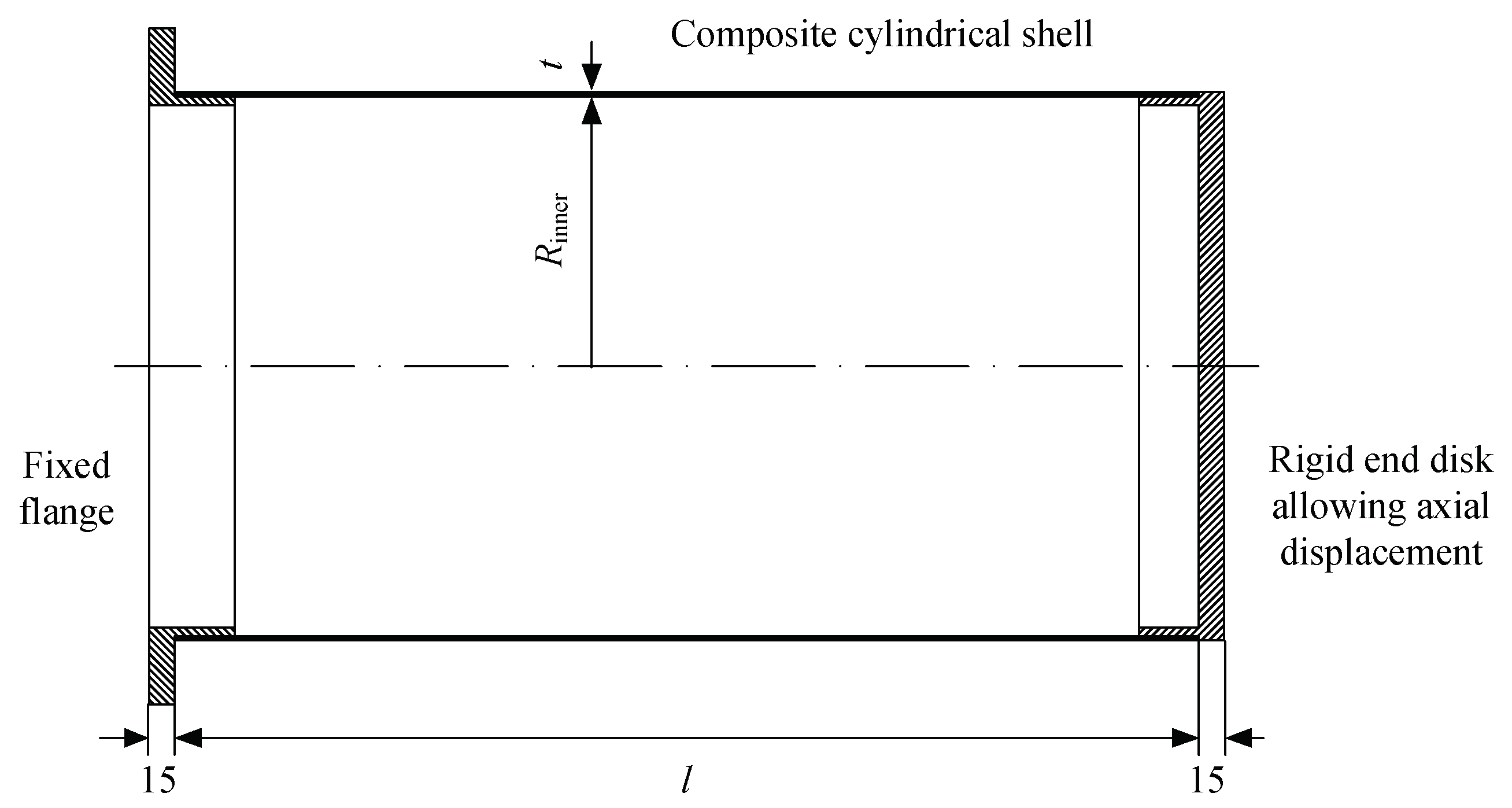
In this section, the results of calculations of the critical buckling pressure and buckling mode for the composite cylindrical shells with cantilever-like boundary conditions subjected to hydrostatic pressure are discussed. As shown in Figure 5, the composite cylindrical shell has an inner radius Rinner, nominal thickness t and length l. The dimensions of the shells and stacking sequences are listed in Table 1. The mechanical properties of the composite material are characterized by elastic moduli E11 and E22, shear modulus G12 and Poisson’s ratio v12 (listed in Table 2). The corresponding membrane and bending stiffness coefficients of the shell are calculated (see Table 3) by referring to [12].
The instability pressure corresponding to the circumferential buckle wave number n varies from 2 to 6 and is solved by Equation (26), with the results listed in Table 4. According to Equation (26), the critical buckling pressure of the composite cylindrical shells is obtained. The buckling of the composite cylindrical shell with cantilever-like boundary conditions under hydrostatic pressure is analyzed using the finite element method. Both static and stability analyses are conducted in sequence in order to obtain the critical buckling pressure. The shell is modeled using a three dimensional structural element with six degrees of freedom at each node, involving translations in the x, y and z axes and rotations about the x, y and z axes. The results of the critical buckling pressure testing using the finite element method, analytical solution and experiments [12] are presented in Table 5. Following from the comparison, it can be seen that the deviations given by the analytical solution are 6.42% and 11.71%, respectively, while the deviations of the finite element analysis are 21.62% and 24.80%, respectively. For the buckling mode, the analytical solution and finite element method predict the same result, characterized by four waveforms in the circumferential direction (see Figure 6).
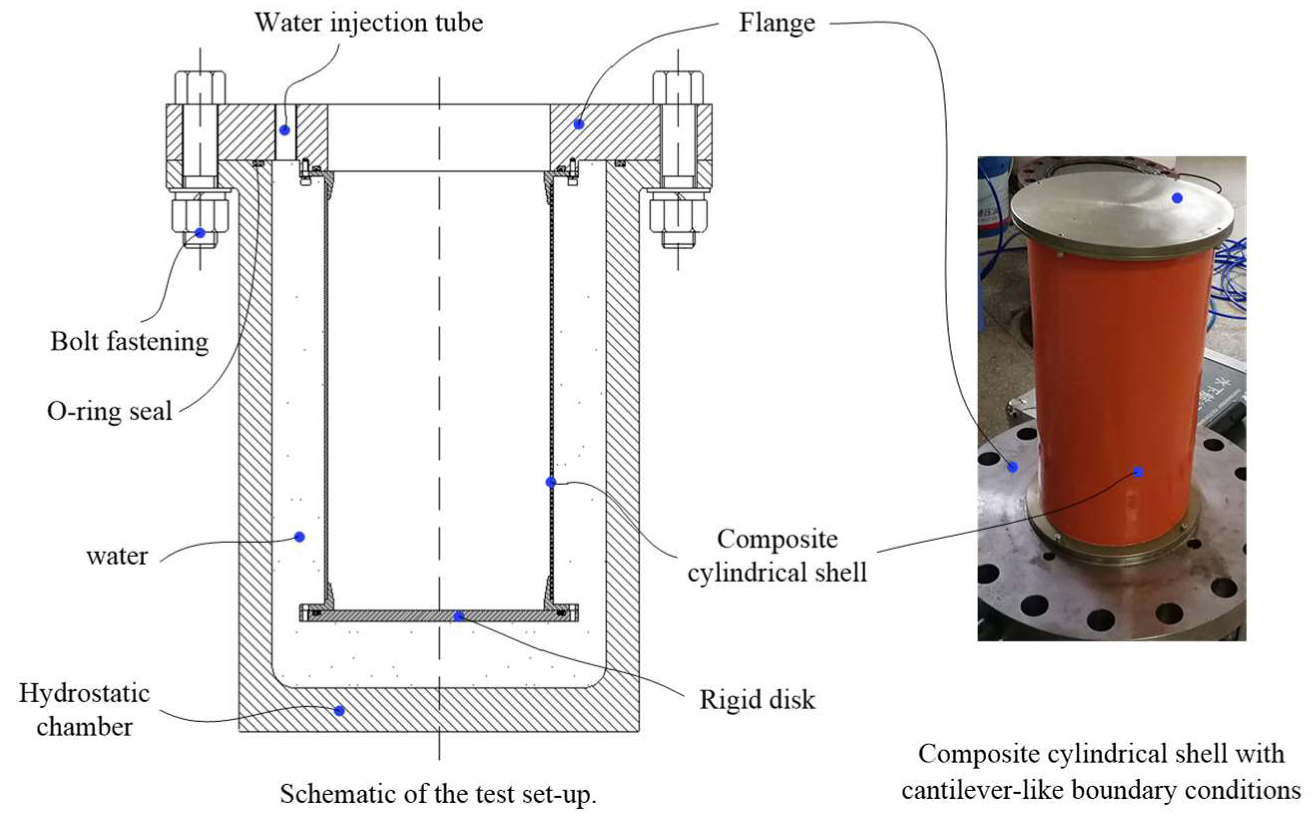
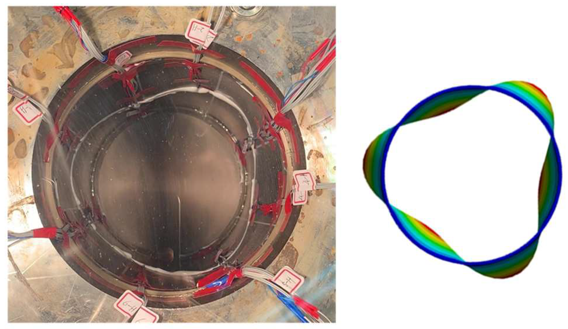
Furthermore, a composite cylindrical shell with a thickness of 3 mm, length of 405 mm and inner radius of 100 mm is produced using a T700-12K carbon–epoxy towpreg. The filament winding sequence is [±90]2/([±20]/[±90]/[±40]/[±90]/[±60]/[±90])2/[±90]. The mechanical properties are E11 = 102 GPa, E22 = 7 GPa, G12 = 8 GPa, v12 = 0.3. An external hydrostatic load testing is conducted in a hydrostatic chamber. As shown in Figure 7, one end of the shell is fixed on the flange and the other end is connected to the rigid disk. This structural form is equivalent to the cantilever-like boundary conditions. Water is continuously injected into the chamber to apply hydrostatic pressure. Thus, the composite cylindrical shell is submerged into the chamber and experiences external hydrostatic pressure on the shell and the rigid disk. Figure 8 shows the buckling mode observed in the test and using the finite element analysis. The critical buckling pressure and buckling mode obtained using the analytical method, FEM and testing are listed in the Table. Through the comparison, it can be seen that the buckling mode predicted by the analytical solution and FEM is consistent with the experimental result, which is characterized by three waves in the circumferential direction. As for the critical buckling pressure, both the analytical solution and FEM give relatively small deviations. Reviewing the buckling mode of analytical examples listed in Table 5 and Table 6, it is found that the initial configuration, such as stacking sequence, radius and length, causes changes in the first mode of buckling and critical buckling pressure of the shell.

4. Conclusions

An analytical solution for the buckling of a composite cylindrical shell subjected to hydrostatic pressure was derived using the Galerkin method. The boundary conditions of the cylindrical shell are that one end is fixed and the other end is connected to a rigid disk allowing axial displacement. The axial displacement of the shell is approximated by the first mode shape of transverse vibration of the clamped sliding beam. The circumferential displacement and deflection are approximated by the first derivation of the beam function. Analytical examples were conducted and the calculation results were compared to the finite element analysis and experimental results. It was shown that the buckling mode of the composite cylindrical shell predicted by the analytical solution was in good agreement with the finite element analysis, while the mode was consistent with the buckling shape observed in the experiment. As for the critical buckling pressure, the analytical method proposed in this study gave a deviation of about 10% in comparison with the test results. The analytical solution derived in the work would be suitable for predicting the critical buckling pressure and buckling mode for thin-walled composite cylindrical shells with cantilever-like boundary conditions under hydrostatic pressure. In future research, the transverse shear effect will be taken into consideration to construct linearized buckling equations to study the buckling of mid-thickness and thick-walled composite cylindrical shells.

Author Contributions

Validation, L.-L.J., Z.-Q.Y.; writing—original draft preparation, K.-C.S.; supervision, G.P. All authors have read and agreed to the published version of the manuscript.

Funding

This research was funded by the National Natural Science Foundation of China (52101376) and the Fundamental Research Funds for the Central Universities (3102019JC006).

Institutional Review Board Statement

Ethical review and approval were waived for this study not involving humans or animals.

Informed Consent Statement

Not applicable.

Data Availability Statement

Not applicable.

Conflicts of Interest

The authors declare no conflict of interest.

References

  1. Smith, C.S. Design of submersible pressure hulls in composite materials. Mar. Struct. 1991, 4, 141–182. [Google Scholar] [CrossRef]
  2. Ross, C. A conceptual design of an underwater vehicle. Ocean. Eng. 2006, 33, 2087–2104. [Google Scholar] [CrossRef]
  3. Hajlaoui, A.; Dammak, F. A modified first shear deformation theory for three-dimensional thermal post-buckling analysis of FGM plates. Meccanica 2021, 56, 1–17. [Google Scholar] [CrossRef]
  4. Hajlaoui, A.; Chebbi, E.; Dammak, F. Three-dimensional thermal buckling analysis of functionally graded material structures using a modified FSDT-based solid-shell element. Int. J. Press. Vessel. Pip. 2021, 194, 104547. [Google Scholar] [CrossRef]
  5. Hajlaoui, A.; Wali, M.; Jdidia, M.B.; Dammak, F. An improved enhanced solid shell element for static and buckling analysis of shell structures. Mech. Ind. 2016, 17, 510. [Google Scholar] [CrossRef]
  6. Hajlaoui, A.; Jarraya, A.; Bikri, K.E.; Dammak, F. Buckling analysis of functionally graded materials structures with enhanced solid-shell elements and transverse shear correction. Compos. Struct. 2015, 132, 87–97. [Google Scholar] [CrossRef]
  7. Carvelli, V.; Panzeri, N.; Poggi, C. Buckling strength of GFRP under-water vehicles. Compos. Part B Eng. 2001, 32, 89–101. [Google Scholar] [CrossRef]
  8. Maali, M.; Bayrak, B.; Kiliç, M.; Sagiroglu, M.; Aydin, A.C. Buckling behavior of double-layered composite cylindrical shells. Int. J. Press. Vessel. Pip. 2021, 191, 104328. [Google Scholar] [CrossRef]
  9. Ouellette, P.; Hoa, S.V.; Sankar, T.S. Buckling of composite cylinders under external pressure. Polym. Compos. 1986, 7, 363–374. [Google Scholar] [CrossRef]
  10. Denardo, N.; Pinto, M.; Shukla, A. Hydrostatic and shock-initiated instabilities in double-hull composite cylinders. J. Mech. Phys. Solids 2018, 120, 96–116. [Google Scholar] [CrossRef]
  11. Gupta, S.; Matos, H.; LeBlanc, J.M.; Shukla, A. Shock initiated instabilities in underwater cylindrical structures. J. Mech. Phys. Solids 2016, 95, 188–212. [Google Scholar] [CrossRef]
  12. Hur, S.H.; Son, H.J.; Kweon, J.H.; Choi, J.H. Postbuckling of composite cylinders under external hydrostatic pressure. Compos. Struct. 2008, 86, 114–124. [Google Scholar] [CrossRef]
  13. Ross, C.T.F.; Little, A.P.F.; Haidar, Y.; Waheeb, A.A. Buckling of Carbon/Glass composite tubes under uniform external hydrostatic pressure. Strain 2011, 47, 156–174. [Google Scholar] [CrossRef]
  14. Moon, C.J.; Kim, I.H.; Choi, B.H.; Kweon, J.H.; Choi, J.H. Buckling of filament-wound composite cylinders subjected to hydrostatic pressure for underwater vehicle applications. Compos. Struct. 2010, 92, 2241–2251. [Google Scholar] [CrossRef]
  15. Tang, W.X.; Zhang, S.; Zhang, J.; Tang, Z. Experimental study on the failure modes of circumferentially corrugated cylinders under external hydrostatic pressure. Thin-Walled Struct. 2020, 156, 106988. [Google Scholar] [CrossRef]
  16. Hernandez-Moreno, H.; Douchin, B.; Collombet, F.; Choqueuse, D.; Davies, P. Influence of winding pattern on the mechanical behavior of filament wound composite cylinders under external pressure. Compos. Sci. Technol. 2008, 68, 1015–1024. [Google Scholar] [CrossRef] [Green Version]
  17. Messager, T. Buckling of imperfect laminated cylinders under hydrostatic pressure. Compos. Struct. 2001, 53, 301–307. [Google Scholar] [CrossRef] [Green Version]
  18. Nguyen, H.; Elishakoff, I.; Nguyen, V.T. Buckling under the external pressure of cylindrical shells with variable thickness. Int. J. Solids Struct. 2009, 46, 4163–4168. [Google Scholar] [CrossRef] [Green Version]
  19. Cho, Y.S.; Oh, D.H.; Paik, J.K. An empirical formula for predicting the collapse strength of composite cylindrical-shell structures under external pressure loads. Ocean. Eng. 2019, 172, 191–198. [Google Scholar] [CrossRef]
  20. Li, Z.; Duan, M.; An, C. An improved analytical solution for elastic and elastic-plastic buckling of pipes under hydrostatic pressures. Ocean. Eng. 2021, 230, 109009. [Google Scholar] [CrossRef]
  21. Almeida, J.H.S., Jr.; Ribeiro, M.L.; Tita, V.; Amico, S.C. Damage and failure in carbon/epoxy filament wound composite tubes under external pressure: Experimental and numerical approaches. Mater. Des. 2016, 96, 431–438. [Google Scholar] [CrossRef]
  22. Lopatin, A.V.; Morozov, E.V. Buckling of composite cylindrical shells with rigid end disks under hydrostatic pressure. Compos. Struct. 2017, 173, 136–143. [Google Scholar] [CrossRef]
  23. Lopatin, A.V.; Morozov, E.V. Buckling of the composite sandwich cylindrical shell with clamped ends under uniform external pressure. Compos. Struct. 2015, 122, 209–216. [Google Scholar] [CrossRef]
  24. Matos, H.; Kishore, S.; Salazar, C.; Shukla, A. Buckling, vibration, and energy solutions for underwater composite cylinders. Compos. Struct. 2020, 244, 112282. [Google Scholar] [CrossRef]
  25. Imran, M.; Shi, D.; Tong, L.; Elahi, A.; Uddin, M. On the elastic buckling of cross-ply composite closed cylindrical shell under hydrostatic pressure. Ocean. Eng. 2011, 227, 108633. [Google Scholar] [CrossRef]
  26. Hu, H.T.; Su, S.W. Optimization for buckling resistance of fiber-composite laminate shells with and without cutouts. Compos. Struct. 1992, 22, 3–13. [Google Scholar] [CrossRef]
  27. Abrate, S. Optimal design of laminated plates and shells. Compos. Struct. 1994, 29, 269–286. [Google Scholar] [CrossRef]
  28. Geier, B.; Meyer-Piening, H.-R.; Zimmermann, R. On the influence of laminate stacking on buckling of composite cylindrical shells subjected to axial compression. Compos. Struct. 2002, 55, 467–474. [Google Scholar] [CrossRef]
  29. Maalawi, K. Optimal buckling design of anisotropic rings/long cylinders under external pressure. J. Mech. Mater. Struct. 2008, 3, 775–793. [Google Scholar] [CrossRef] [Green Version]
  30. Imran, M.; Shi, D.-Y.; Tong, L.-L.; Elahi, A.; Waqas, H.M.; Uddin, M. Multi-objective design optimization of composite submerged cylindrical pressure hull for minimum buoyancy factor and maximum buckling load capacity. Def. Technol. 2021, 17, 1190–1206. [Google Scholar] [CrossRef]
  31. Messager, T.; Pyrz, M.; Gineste, B.; Chauchot, P. Optimal laminations of thin underwater composite cylindrical vessels. Compos. Struct. 2002, 58, 529–537. [Google Scholar] [CrossRef] [Green Version]
  32. Shen, K.C.; Pan, G. Optimizing the buckling strength of filament winding composite cylinders under hydrostatic pressure. J. Reinf. Plast. Compos. 2018, 37, 892–904. [Google Scholar]
  33. Lee, G.C.; Kweon, J.H.; Choi, J.H. Optimization of composite sandwich cylinders for underwater vehicle application. Compos. Struct. 2013, 96, 691–697. [Google Scholar] [CrossRef]
  34. Shen, K.C.; Pan, G. Buckling and strain response of filament winding composite cylindrical shell subjected to hydrostatic pressure: Numerical solution and experiment. Compos. Struct. 2021, 276, 114534. [Google Scholar] [CrossRef]
  35. Vasiliev, V.V. Mechanics of Composite Structures; Taylor & Francis: Washington, DC, USA, 1993. [Google Scholar]
  36. Vasiliev, V.V.; Morozov, V.E. Advanced Mechanics of Composite Materials, 2nd ed.; Elsevier: Amsterdam, The Netherlands, 2007. [Google Scholar]
  37. Blevins, R.D. Formulas for Natural Frequency and Mode Shape; Krieger Publishing Company: Malabar, FL, USA, 2001. [Google Scholar]
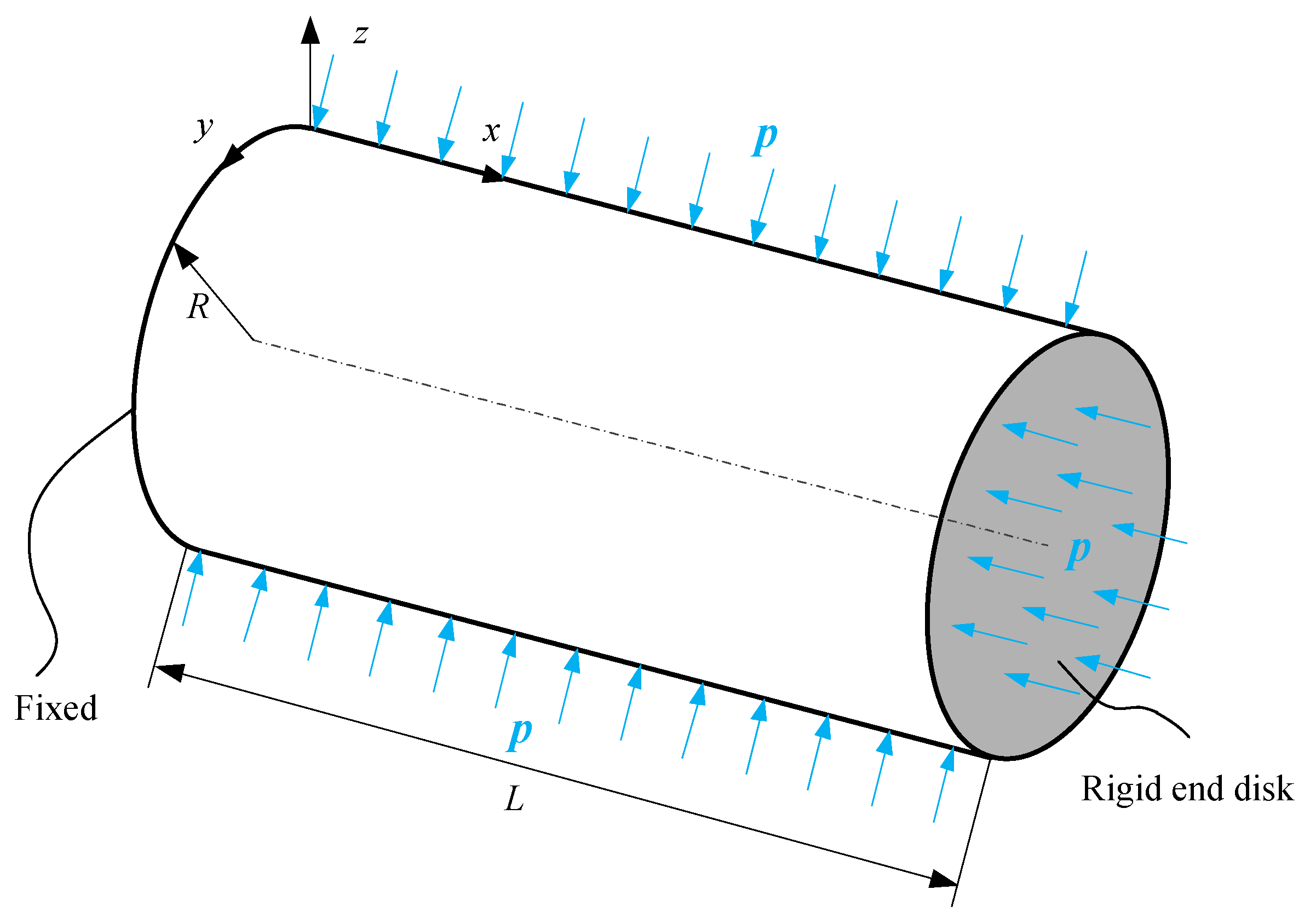
Figure 1. Composite cylindrical shell with cantilever-like boundary conditions under hydrostatic pressure.
Jmse 10 00126 g001
Figure 2. Example of the buckling mode of the cylindrical shell (n = 3).
Jmse 10 00126 g002
Figure 3. The first mode shape of clamped sliding beam function.
Jmse 10 00126 g003
Figure 4. The first derivation of the clamped sliding beam function.
Jmse 10 00126 g004
Figure 5. Geometry of the cylindrical shell.
Jmse 10 00126 g005
Figure 6. Buckling mode of shell NO.2.
Jmse 10 00126 g006
Figure 7. Schematic of the test setup and boundary conditions.
Jmse 10 00126 g007
Figure 8. Buckling mode of the composite cylindrical shell.
Jmse 10 00126 g008
Table 1. Dimensions of the composite cylinders.
IDStacking SequenceRinner/mmt/mml/mm
NO.1[0/90]12T1582.52564
NO.2[0/90]12T1582.52600
Table 2. Mechanical properties.
PropertySymbolValueUnit
Elastic modulusE11162GPa
E229.6GPa
Poisson’s ratiov120.298
Shear modulusG126.1GPa
Table 3. Membrane and bending stiffness coefficients.
Extensional stiffnessValueBending StiffnessValue
A112.1736 × 108D11115.0268
A127.2472 × 106D123.8352
A222.1736 × 108D22115.0268
A661.5372 × 107D668.1349
Table 4. Analytical results.
Circumferential Wave Numbers n23456
Instability pressure pn/MPaNO.14.3870.94980.63850.765210.337
NO.23.92120.86750.61440.755910.296
Table 5. Comparison of the critical buckling pressures.
IDBuckling Pressure/MPa and Buckling Mode
Analytical Method
(Deviation)
Finite Element Method
(Deviation)
Experiment [12]
NO.10.6385 (6.42%)n = 40.7297 (21.62%)n = 40.6
NO.20.6144(11.71%)n = 40.6864 (24.80%)n = 40.55
Table 6. Analytical, FEM and experimental results.
Buckling Pressure/Mpa and Buckling Mode n
Analytical Method (Deviation)Finite Element Method (Deviation)Experiment
3.297 (7.75%)n = 33.02 (1.31%)n = 33.06 n = 3
Publisher’s Note: MDPI stays neutral with regard to jurisdictional claims in published maps and institutional affiliations.