
A Compact Design of Underwater Mining Vehicle for the Cobalt-Rich Crust with General Support Vessel Part A: Prototype and Tests

 ,
,
Abstract
:1. Introduction
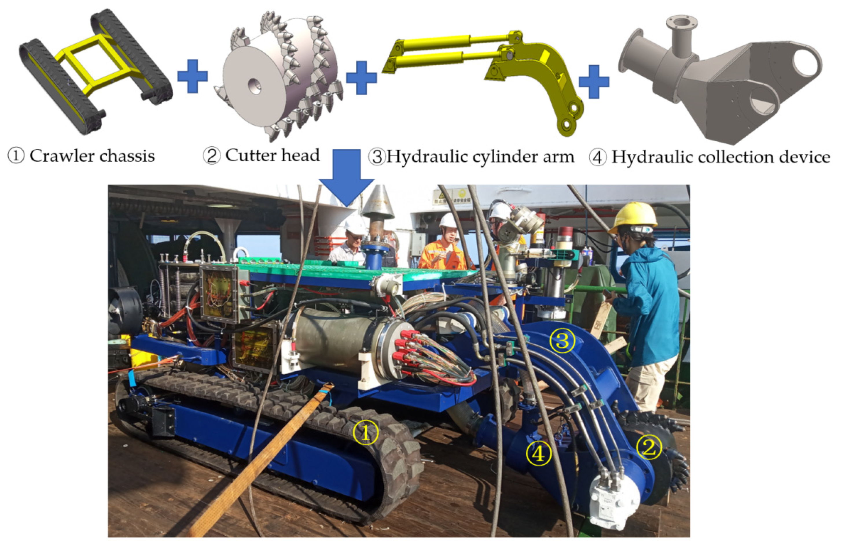
2. Function and Design of the Mining Vehicle
2.1. Requirements
- Meeting the demands of the mining test with the minimum cost and a good maintainability to support broader marine mining research;
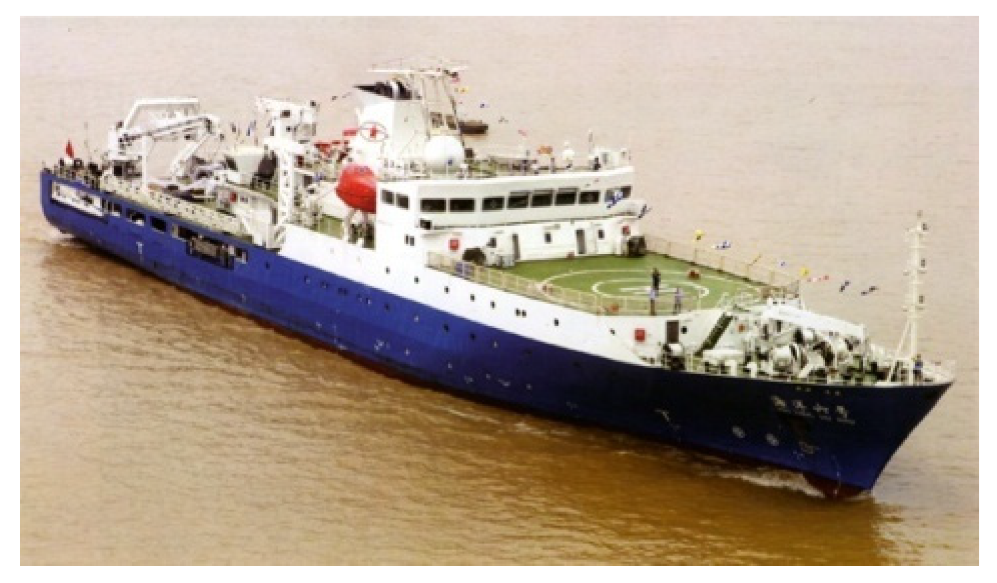
- The general support vessel can be used, particularly the launch and recovery system and umbilical.
- The mining vehicle can work on the hard seafloor of the slope and adapt to the possible micro-topography;
- The crushing tool can peel off the cobalt-rich crust covered on the rock and crush it to 15–30 mm size;
- The cutter head needs to move up and down to follow the microtopography;
- An efficient and reliable particles collection is required. collected particle size is 0–100 mm;
- Keeping the mining vehicle at the same heading with the support vessel during the launch process.
- The crust thickness measurement determines the depth of cutting, which is an important factor for the ore dilution rate control. The ideal way to measure the crust thickness by a sub-bottom profiler is contactless measurement;
- Positioning and navigation are required as the complex terrain and dark environment.
2.2. Functions
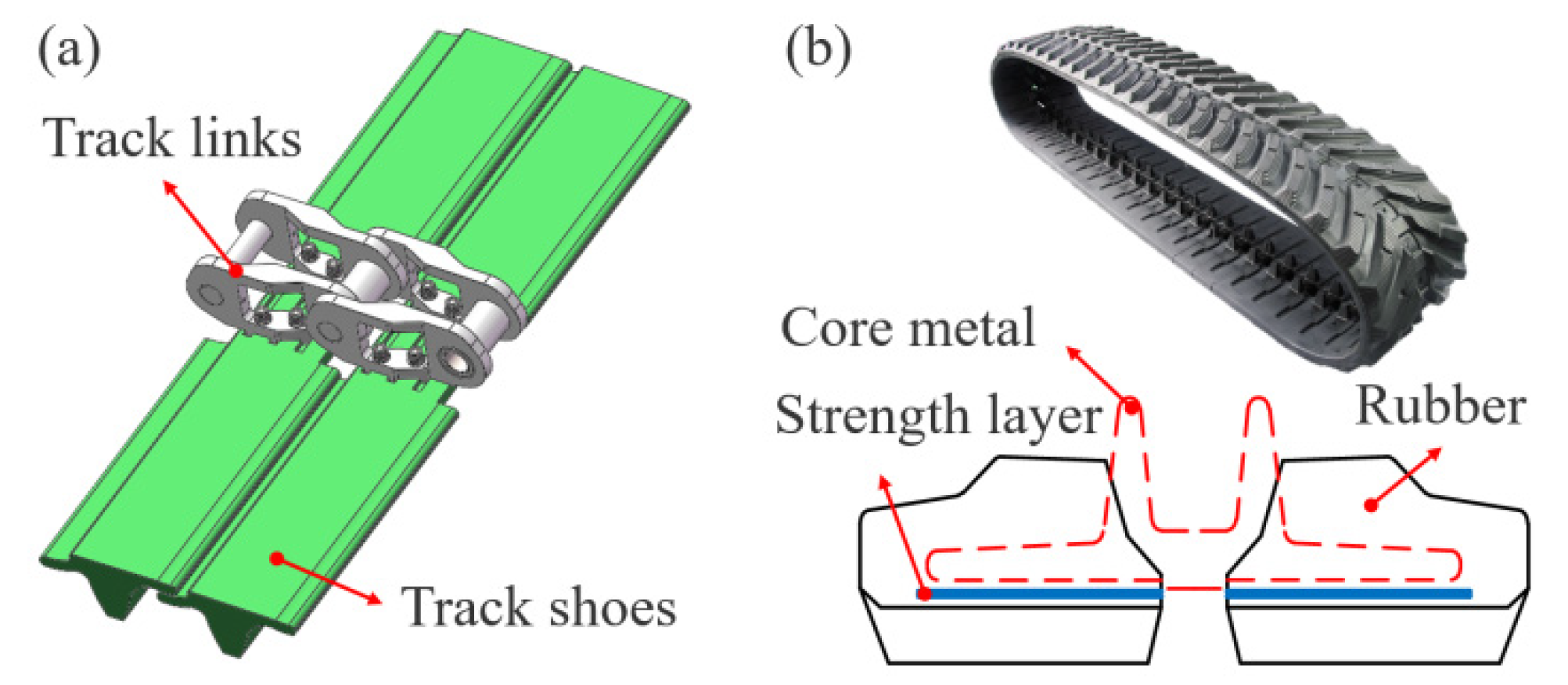
2.2.1. Walking
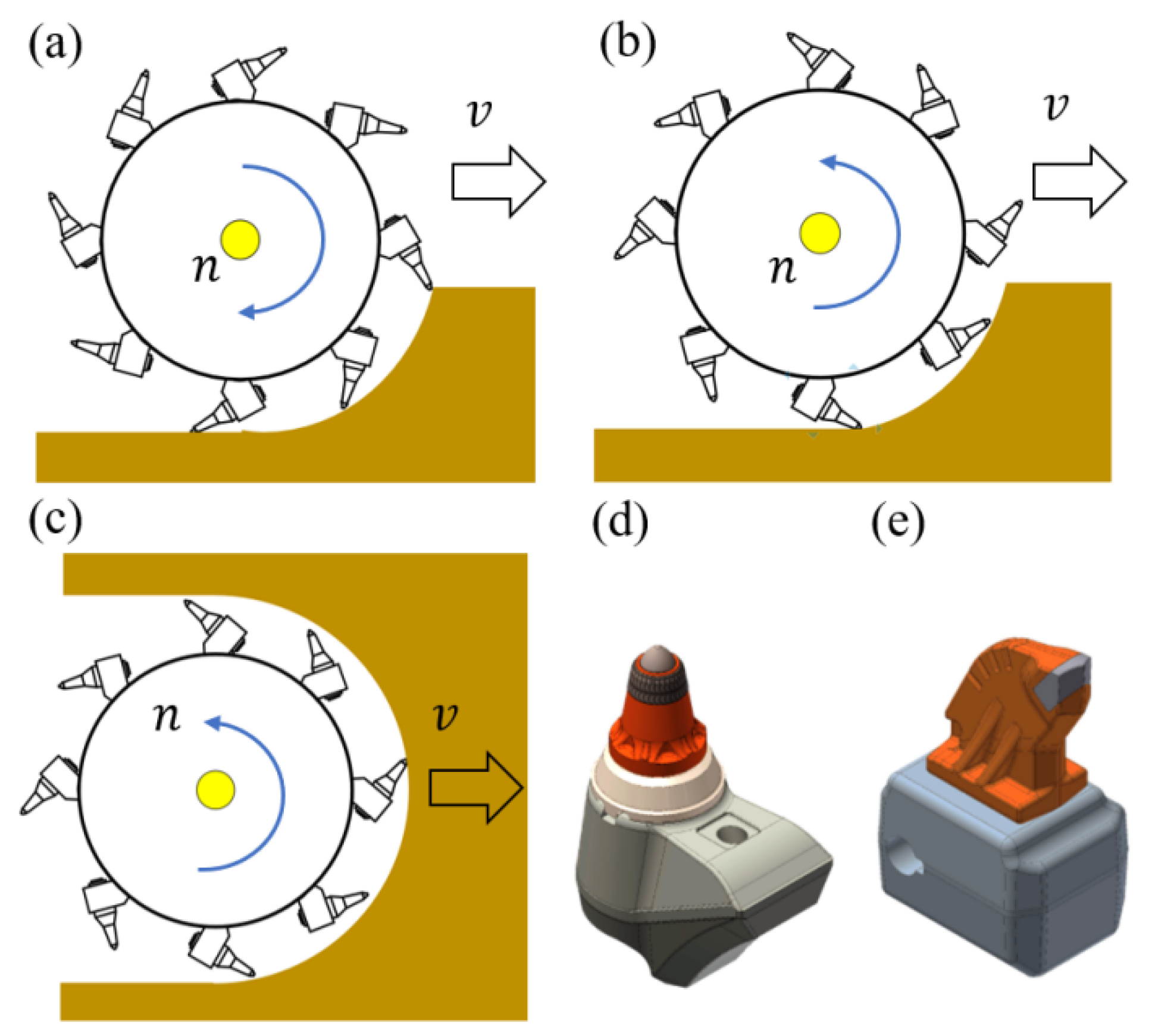
2.2.2. Crushing
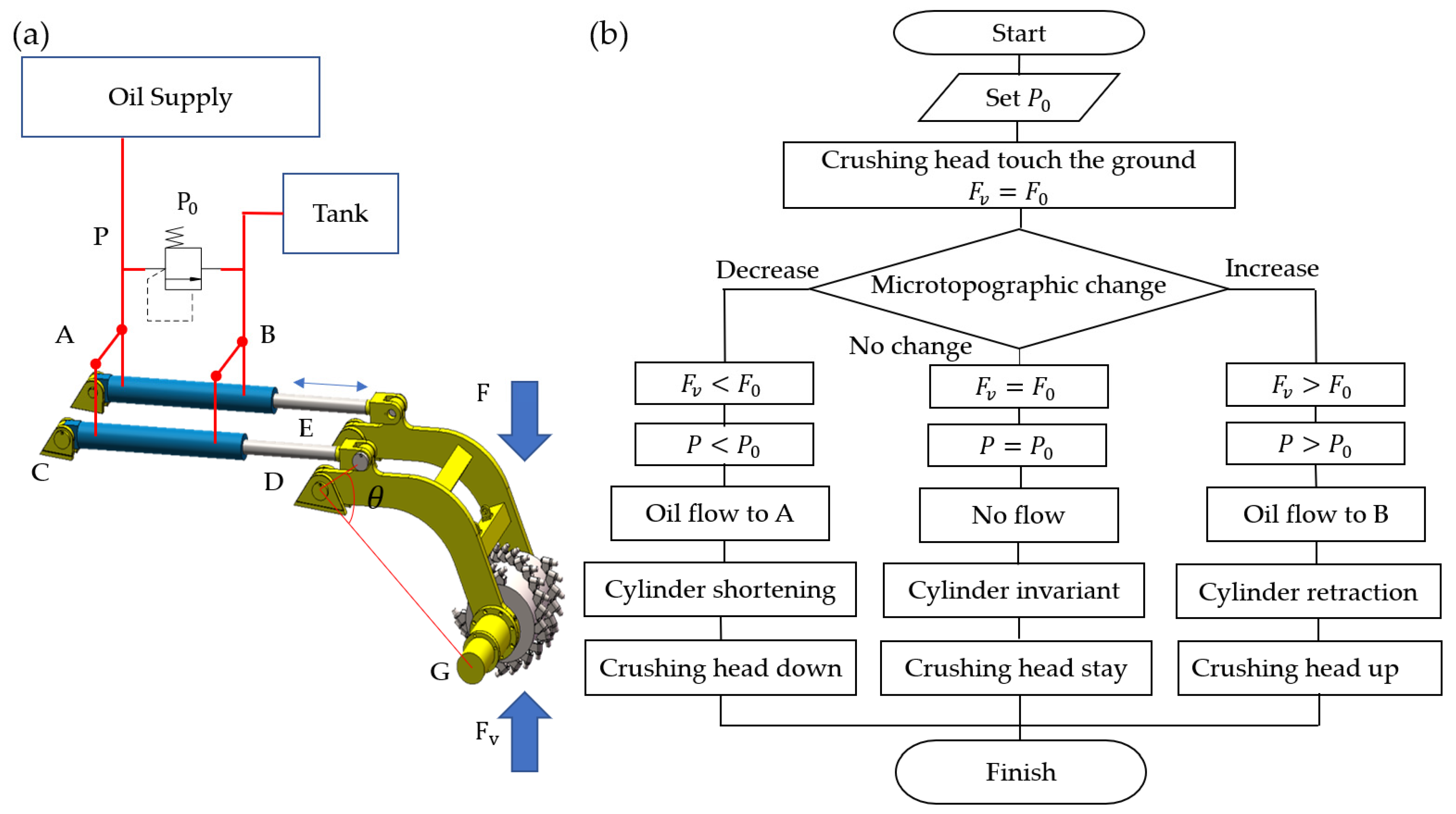
2.2.3. Adaptation
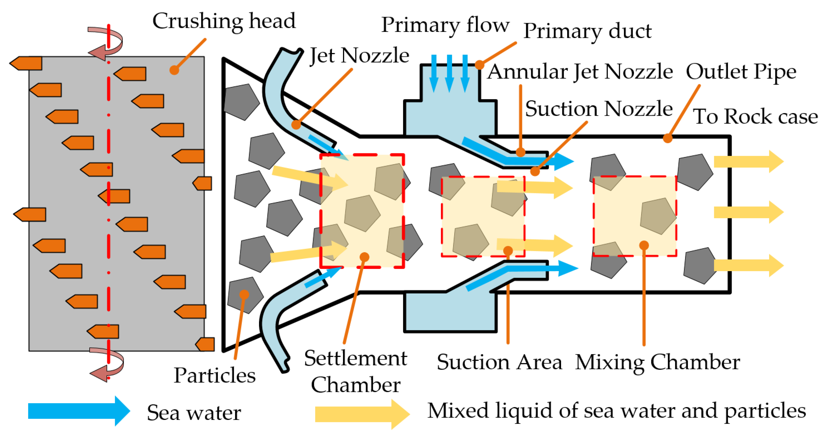
2.2.4. Collecting
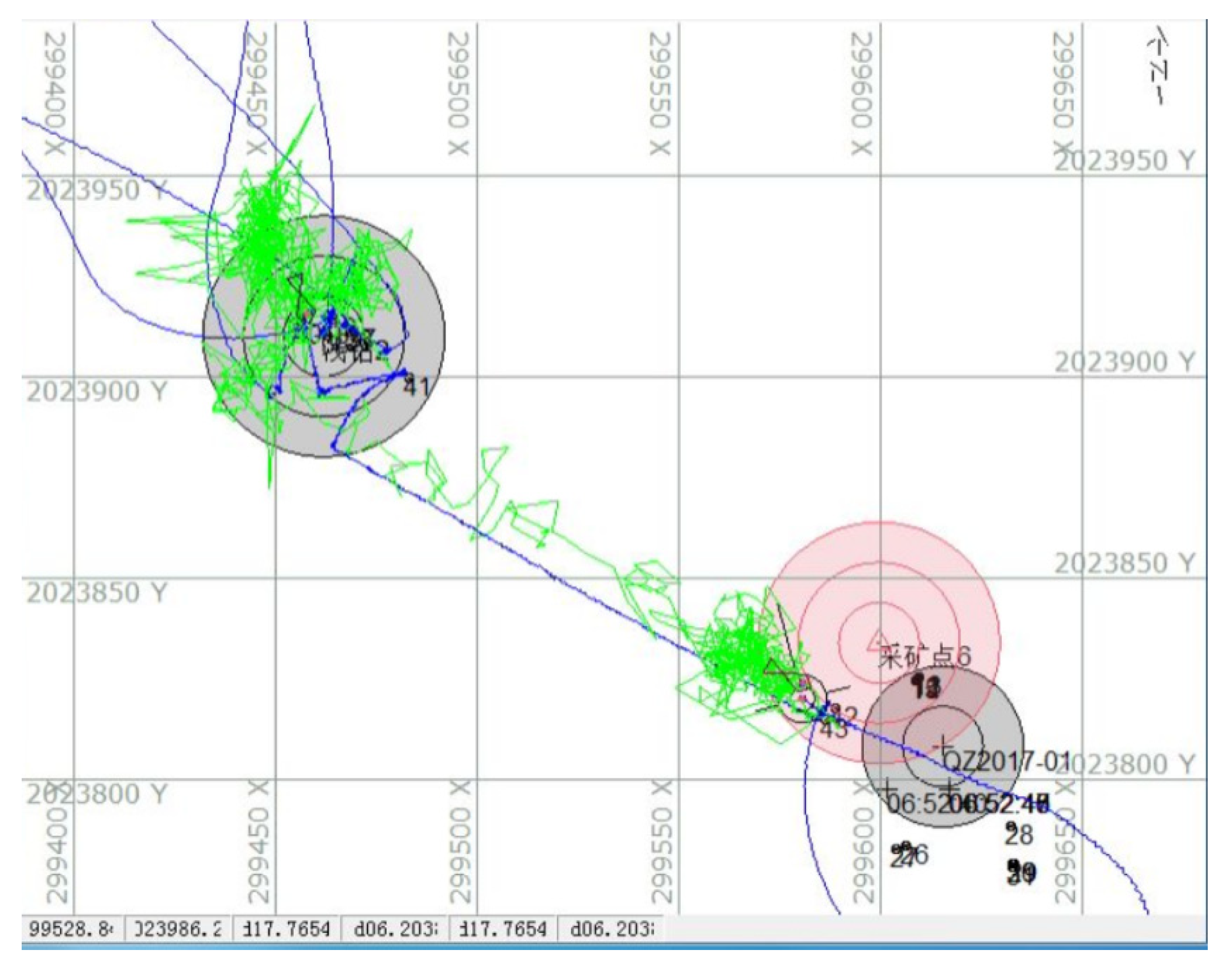
2.2.5. Orientation
2.3. Additional Functions
2.3.1. Crust Bedding Structure Measuring Device
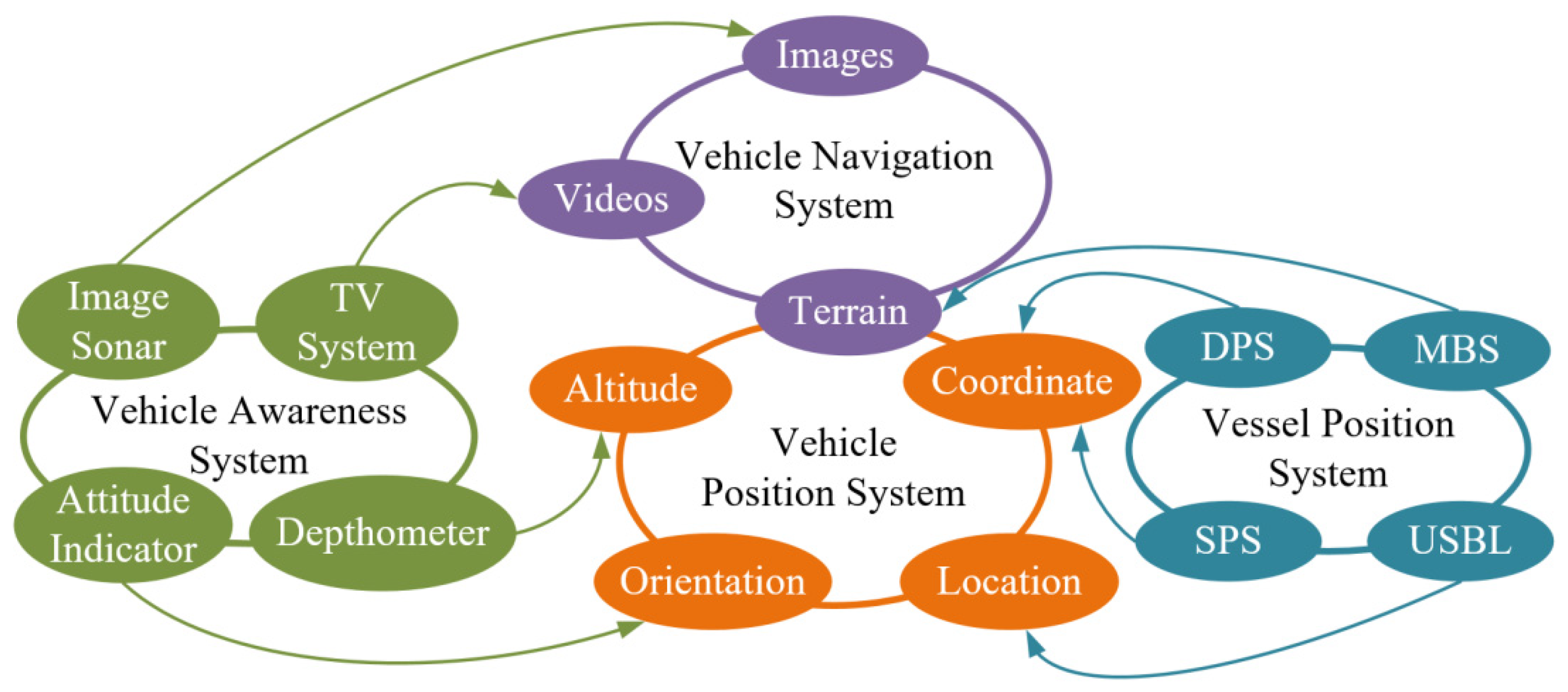
2.3.2. Awareness System and Positioning and Navigation System
2.4. Specifications of the Mining Vehicle
2.4.1. Parameters
2.4.2. Working Modes
3. Mining Test System and Procedure
3.1. Mining Testing System
3.2. Test Procedure
- Step 1: Select test location. The preferred terrain is a seamount with a gentle slope no more than 25°.
- Step 2: Terrain confirmation before test. After reaching the selected operation area, MSB needs to scan the operation area again to obtain a detailed multi-beam topographic map and select the operation point again.
- Step 3: Support vessel positioning. Turn on DPS of the support vessel to the selected coordinates before launch.
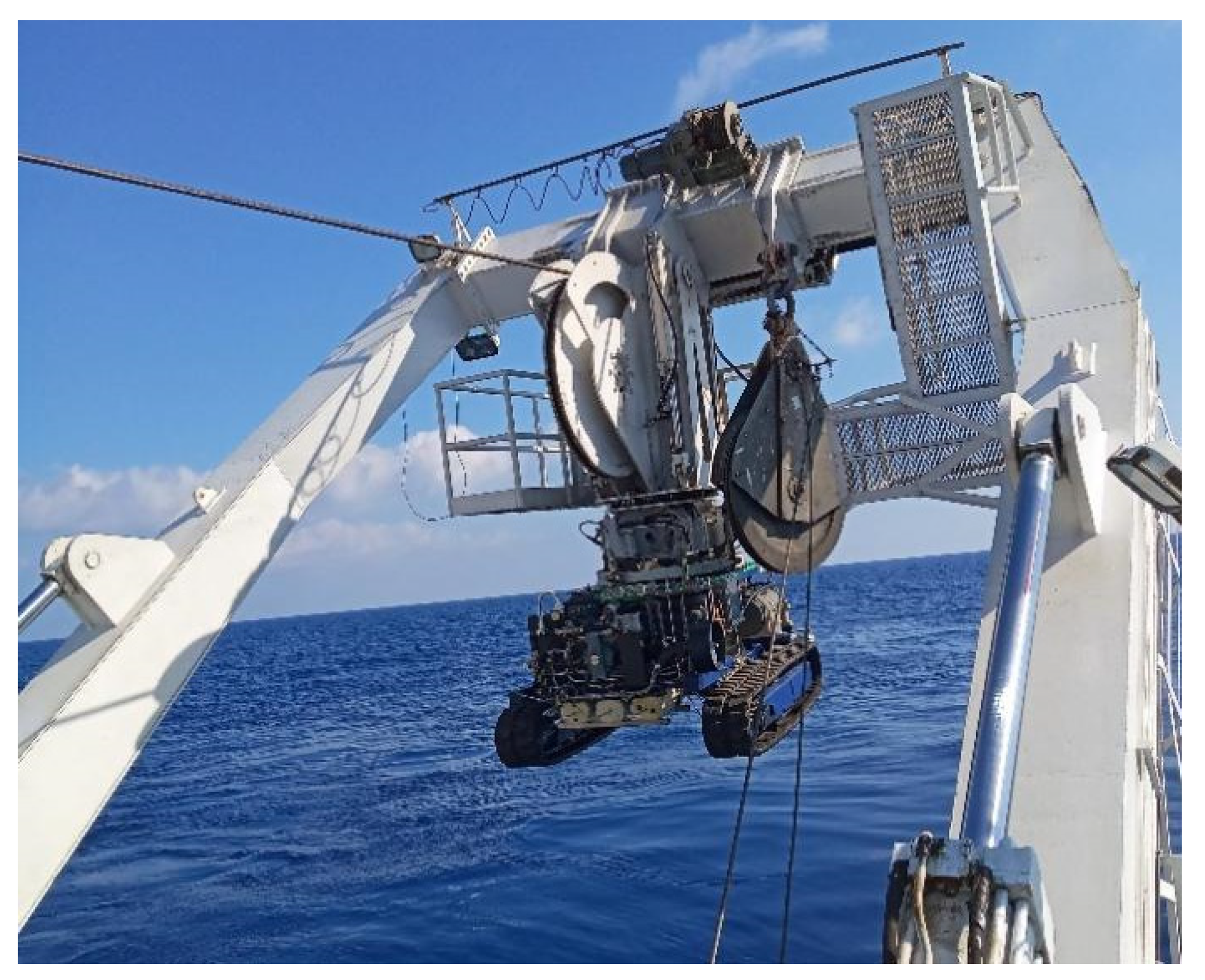
- Step 4: Launch the mining vehicle and turn on the orientation function.
- Step 5: Landing area safety confirmation. Find the flat ground by TV system for landing.
- Step 6: Turn off the orientation function, change the mining vehicle control to manual control, and finish the walking and crushing test.
- Step 7: Observe the environment around the mining vehicle to make sure there are no rock walls.
- Step 8: Slowly recover and tighten the umbilical, observe the deviation direction of the umbilical of the mining truck through the camera, and keep the umbilical in a vertical state. If not, move the support vessel to the right position.
- Step 9: Recovery the umbilical quickly and keep the mining vehicle a certain height above the ground.
- Step 10: Turn on the orientation function, recovery the mining vehicle.
- Step 11: One walking and crushing test is finished.
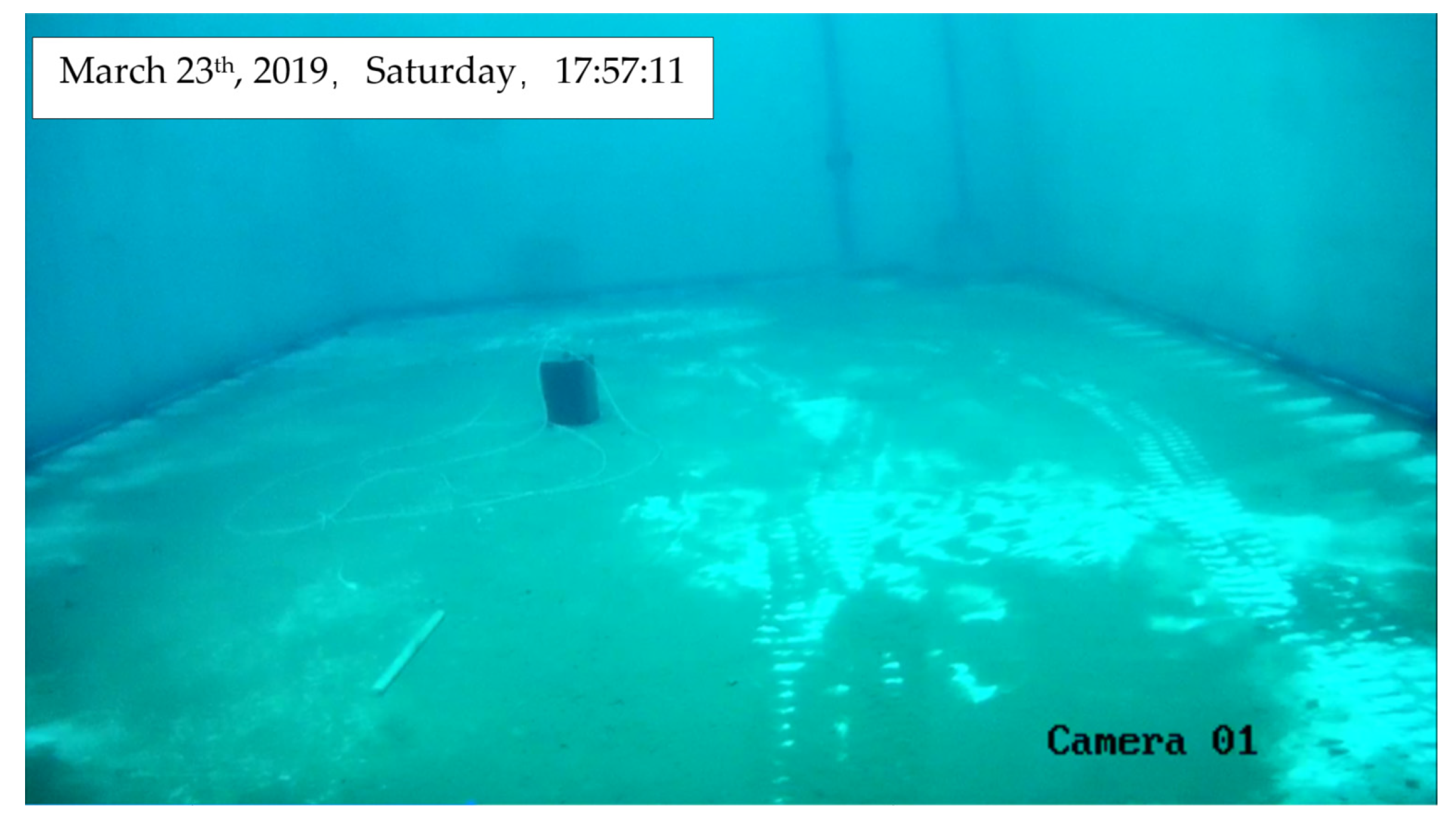
4. Tank Experiments
4.1. Walking Function Test
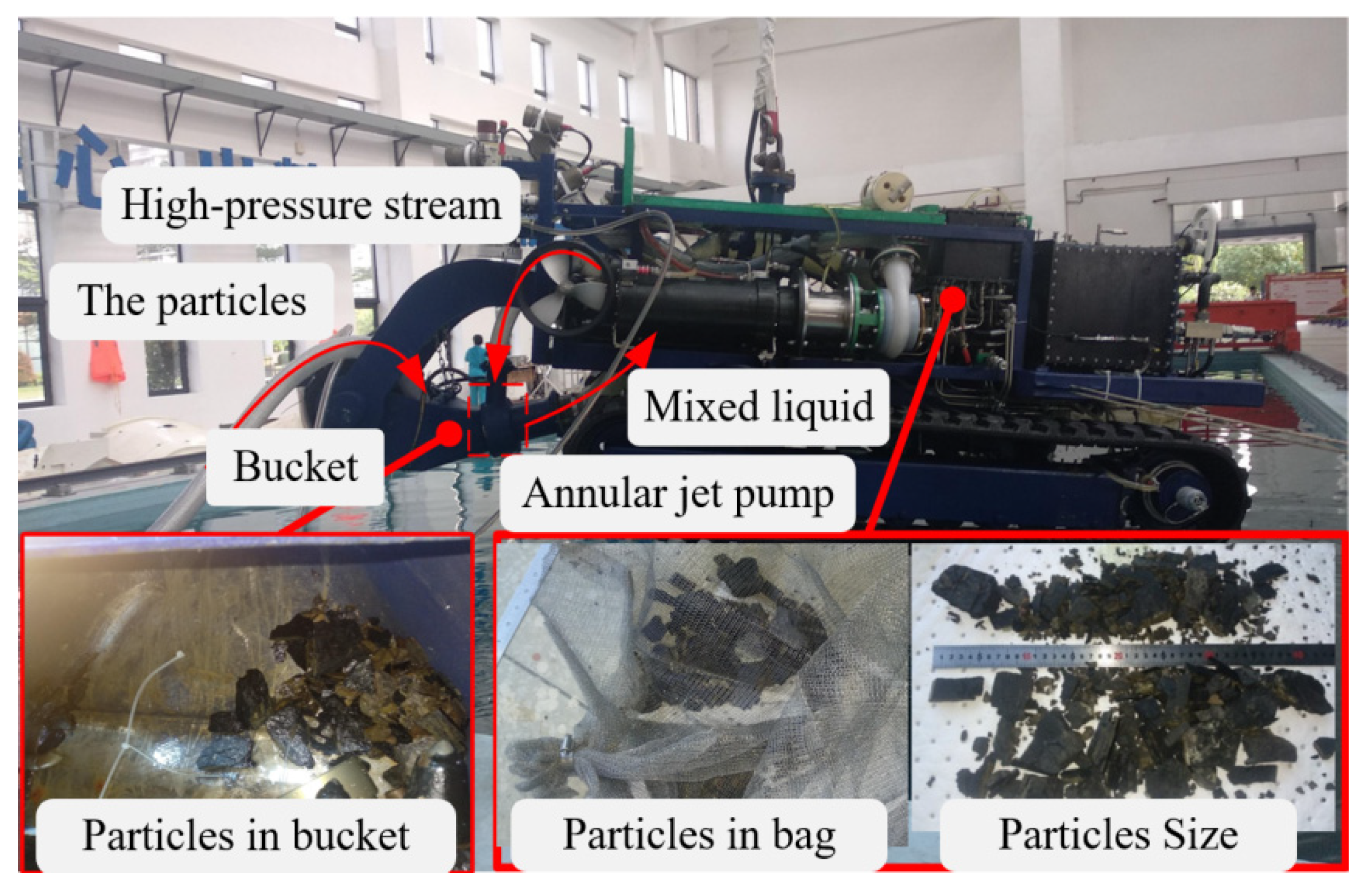
4.2. Collection Function Test
4.3. Cutting Function Test
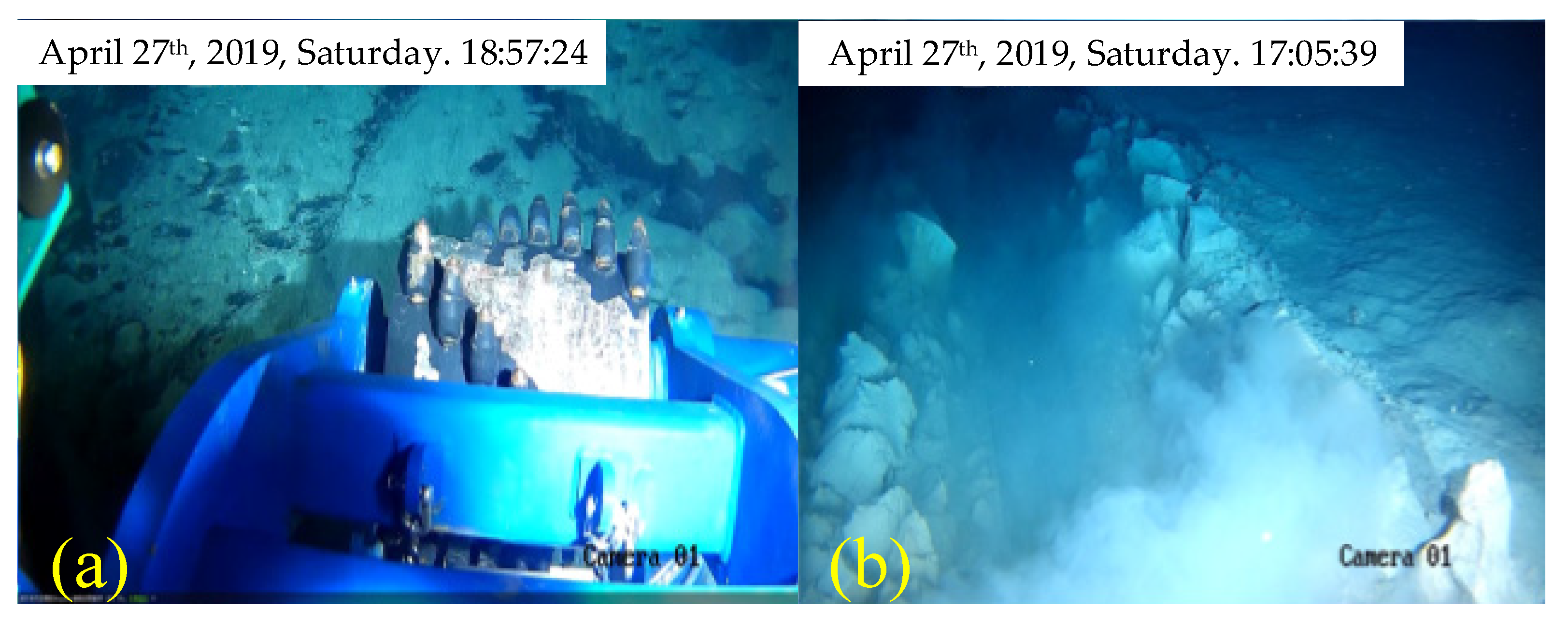
5. Sea Trial
6. Results
7. Conclusions
- (1)
- The walk function worked well in both tank tests and sea trials. The track design worked well in the subsea environment and can be used for the subsea mining vehicle;
- (2)
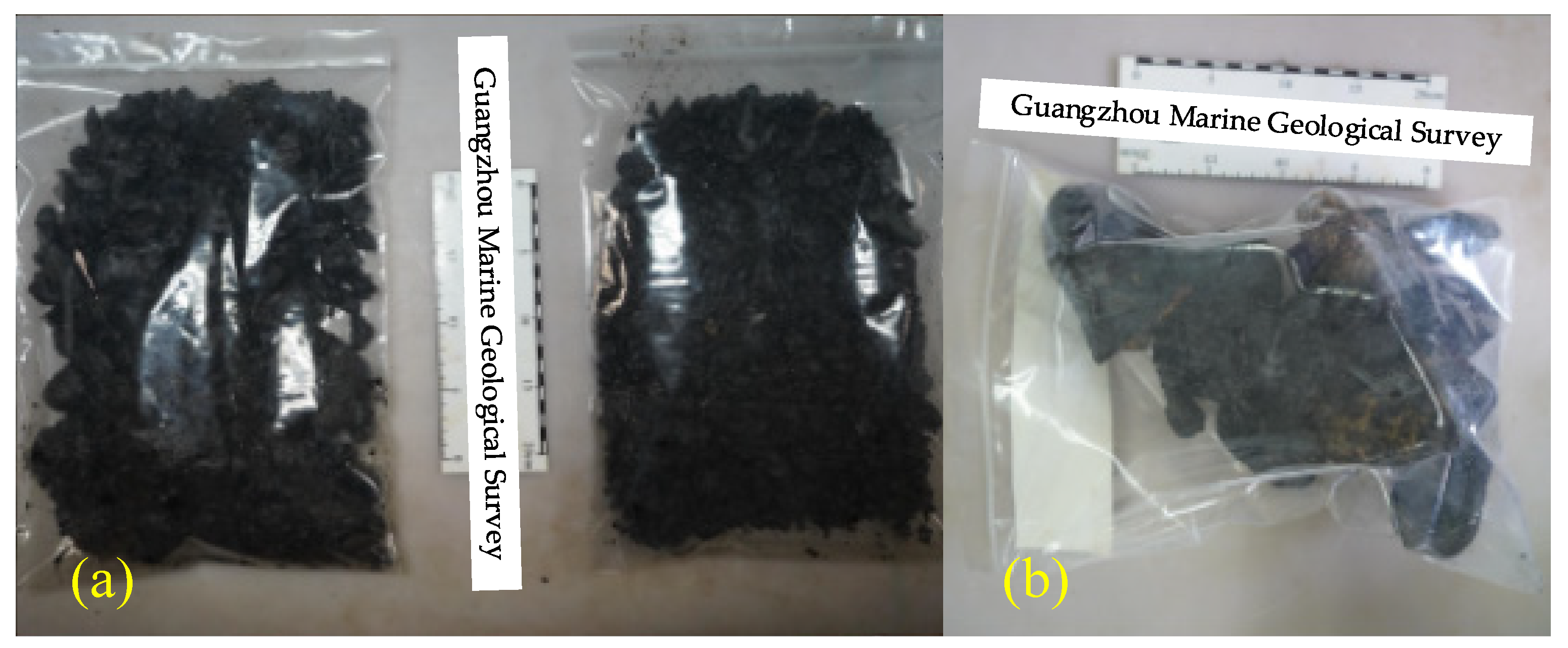
- The crushing and collection functions worked well in sea trials. The crust was crushed to the size of 2 mm and 10 mm in Test 6 and 7, respectively. The sample size can be controlled by the setting of cutting parameters. The crushed crust was successfully collected by the jet pump up to 6 kg in total;
- (3)
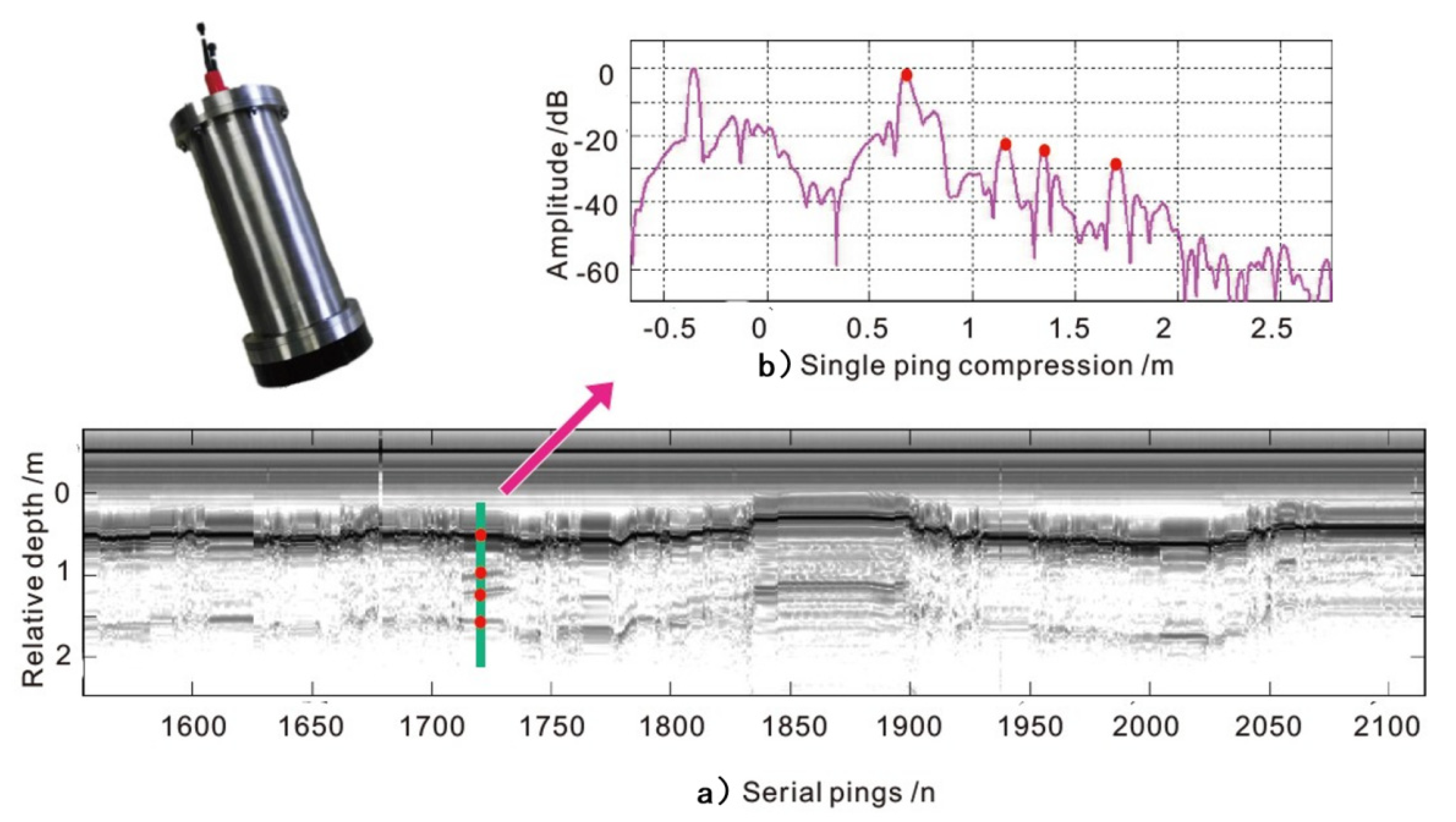
- The crust texture was measured by the onboard sonar successfully, and clearly showed the texture from −0.5 m to 2.5 m. The onboard sonar can be used for the crust texture measurement;
- (4)
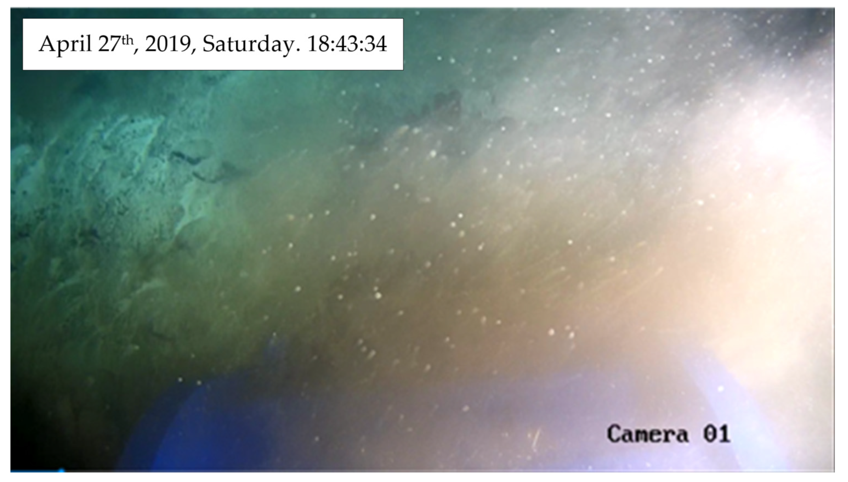
- The cameras captured the images of subsea environment, but the actions of crushing and sample collection produced plumes, which blocked the camera vision. In this situation, the front image sonar can be used to keep the vehicle away from big rocks;
- (5)
- The thrusters worked well in the launch and recovery processes. The thruster design can be used for the mining vehicle orientation.
Author Contributions
Funding
Acknowledgments
Conflicts of Interest
Abbreviations
| ¡VAMOS! | Viable Alternative Mine Operating System |
| ROV | Remote Operated Vehicle |
| SMD | Soil Machine Dynamics Ltd. |
| JOGMEC | Japan Oil, Gas and Metals National Corporation |
| SMS | Seafloor Massive Sulfide |
| IDSSE | Institute of Deep-sea Science and Engineering |
| CAS | Chinese Academy of Sciences |
| GMGS | Guangzhou Marine Geological Survey |
| DPS | Dynamic Positioning System |
| SPS | Ship Positioning System |
| MBS | Multi-beam Bathymetry System |
| USBL | Ultra-Short Baseline |
| TOML | Tonga Offshore Mining Limited |
| HFSSP | High-Frequency Submersible Sub-Bottom Profiler |
| EVs | Electric Vehicles |
| NORI | Nauru Ocean Resources, Inc |
| CCZ | Clarion-Clipperton Zone |
| HMI | Human-Machine Interface |
| DSMF | Deep Sea Mining Finance Limited |
References
- Drazen, J.C.; Smith, C.R.; Gjerde, K.M.; Haddock, S.H.D.; Carter, G.S.; Choy, C.A.; Clark, M.R.; Dutrieux, P.; Goetze, E.; Hauton, C.; et al. Opinion: Midwater ecosystems must be considered when evaluating environmental risks of deep-sea mining. Proc. Natl. Acad. Sci. USA 2020, 117, 17455–17460. [Google Scholar] [CrossRef] [PubMed]
- Where Should Metals for the Green Transition Come from? Available online: https://www.autoevolution.com/pdf/news_attachements/ocean-floor-could-be-the-next-el-dorado-for-ev-battery-raw-materials-142915.pdf (accessed on 7 January 2022).
- Koschinsky, A.; Heinrich, L.; Boehnke, K.; Cohrs, J.C.; Markus, T.; Shani, M.; Singh, P.; Smith Stegen, K.; Werner, W. Deep-sea Mining: Interdisciplinary Research on Potential Environmental, Legal, Economic, and Societal Implications. Integr. Environ. Assess. Manag. 2018, 14, 672–691. [Google Scholar] [CrossRef] [PubMed]
- Hong, S.; Kim, H.W.; Yeu, T.; Choi, J.S.; Lee, Y.H.; Lee, J.K. Technologies for Safe and Sustainable Mining of Deep-Seabed Minerals. In Environmental Issues of Deep-Sea Mining; Sharma, R., Ed.; Springer: Cham, Switzerland, 2019; pp. 95–142. [Google Scholar]
- Halkyard, J. Technology for mining cobalt rich manganese crusts from seamounts. In Proceedings of the OCEANS ‘85—Ocean Engineering and the Environment, San Diego, CA, USA, 12–14 November 1985. [Google Scholar]
- Nautilus Minerals Officially Sinks, Shares Still Trading. Available online: https://www.mining.com/nautilus-minerals-officially-sinks-shares-still-trading (accessed on 7 January 2022).
- Ishiguro, S.; Yamauchi, Y.; Odaka, H.; Akiyama, S. Development of mining element engineering test machine for operating in seafloor hydrothermal deposits. Mitsubishi Heavy Ind. Tech. Rev. 2013, 50, 21–27. [Google Scholar]
- Ishiguro, S.; Masuda, M.; Komatsu, M.; Norihiro, Y.; Seiya, K. Development of the Pilot System for Test of Excavating and Ore lifting of Seafloor Polymetallic Sulfides. Mitsubishi Heavy Ind. Tech. Rev. 2018, 55, 1–7. [Google Scholar]
- JOGMEC Conducts World’s First Successful Excavation of Cobalt-Rich Seabed in the Deep Ocean. Available online: http://tokiox.com/wp/ogmec-conducts-successful-excavation-of-cobalt-rich/?lang=en (accessed on 7 January 2022).
- Winkelman, M.O.; Dijxhoorn, D.; Marcus, O.P. Novel Solution for Mining Minerals: ¡VAMOS! In Proceedings of the Western Dredging Association Dredging Summit & Expo ‘18, Norfolk, VA, USA, 25–28 June 2018.
- Bleier, M.; Almeida, C.; Ferreira, A.; Pereira, R.; Matias, B.; Almeida, J.; Pidgeon, J.; van der Lucht, J.; Schilling, K.; Martins, A.; et al. 3d Underwater Mine Modelling in the ¡Vamos! Project. Int. Arch. Photogramm. Remote Sens. Spat. Inf. Sci. 2019, XLII-2/W10, 39–44. [Google Scholar] [CrossRef] [Green Version]
- Almeida, J.; Martins, A.; Almeida, C.; Dias, A.; Silva, E. Positioning. Navigation and Awareness of the ¡VAMOS! Underwater Robotic Mining System. In Proceedings of the 2018 IEEE/RSJ International Conference on Intelligent Robots and Systems (IROS), Madrid, Spain, 1–5 October 2018. [Google Scholar]
- Bakker, E.; Žibret, G.; Rainbird, J. The ¡VAMOS! Sustainable Underwater Mining Solution. Eur. Geol. 2017, 44, 58–62. [Google Scholar]
- Halbach, P.; Jahn, A.; Lucka, M.; Post, J. Marine Co-Rich Ferromanganese Crust Deposits: Description and Formation, Occurrences and Distribution. In Deep-Sea Mining; Sharma, R., Ed.; Springer: Cham, Switzerland, 2017; pp. 65–141. [Google Scholar]
- Halbach, P.; Schneider, S.; Jahn, A.; Cherkashov, G. The potential of rare-earth elements in oxidic deep-sea mineral deposits (ferromanganese nodules and crusts). In Mineral Resources and Mine Development; Martens, P.N., Ed.; Verlag Glückauf GmbH: Essen, Germany, 2013; pp. 161–174. [Google Scholar]
- Liu, Y.G.; He, G.W.; Yao, H.Q.; Yang, Y.; Ren, J.; Guo, L.; Mei, Y. Global distribution characteristics of seafloor cobalt-rich encrustation resources. Miner. Depos. 2013, 35, 1275. [Google Scholar]
- Cruikshank, M.H.; Paul, R.C. Characterization of seabed rocks for mine planning in the EEZ. In Proceedings of the 18th Offshore Technology Conference, Houston, TX, USA, 5–8 May 1986. [Google Scholar]
- Vu, M.T.; Choi, H.S.; Ji, D.H.; Jeong, S.K.; Kim, J.Y. A study on an up-milling rock crushing tool operation of an underwater tracked vehicle. Proc. Inst. Mech. Eng. Part M J. Eng. Marit. Environ. 2017, 233, 283–300. [Google Scholar] [CrossRef]
- JB/T 2602-2016 Construction Machinery-Track Completes. In Machinery Industry Standard of the People’s Republic of China; Machinery Industry Press: Beijing, China, 2016.
- GB/T 20786-2015 Rubber Track; Standardization Administration of the People’s Republic of China: Beijing, China, 2015.
- Zhang, Q.; Zhang, Y.; Zhang, A. Research Status of Benthic Small-scale Crawling Robots. ROBOT 2019, 41, 250–264. [Google Scholar]
- Vu, M.T.; Choi, H.S.; Nguyen, N.D.; Kim, S.K. Analytical design of an underwater construction robot on the slope with an up-cutting mode operation of a cutter bar. Appl. Ocean. Res. 2019, 86, 289–309. [Google Scholar] [CrossRef]
- Yang, N.; Xie, C.; Chen, Y.; Chen, M.; Zheng, J.; Zhang, M.; Li, L. The Design of Sampling Machine for Mineral Resources. In Proceedings of the Twenty-Seventh (2017) International Ocean and Polar Engineering Conference, San Francisco, CA, USA, 25–30 June 2017. [Google Scholar]
- Yamazaki, T.; Sharma, R.; Tsurusaki, K. Microtopographic analysis of cobalt-rich manganese deposits on a mid-pacific seamount. Mar. Geotechnol. 1994, 12, 33–52. [Google Scholar] [CrossRef]
- He, Q.; Li, A.; Zou, X. The Control System Design of a Mining Device Adapting to the Microtopography of Ocean Cobalt-Rich Crusts. In Proceedings of the 2006 6th World Congress on Intelligent Control and Automation, Dalian, China, 21–23 June 2006. [Google Scholar]
- Thornton, B.; Asada, A.; Ura, T.; Ohira, K.; Kirimura, D. The development of an acoustic probe to measure the thickness of ferro-manganese crusts. In Proceedings of the OCEANS’10 IEEE, Sydney, Australia, 24–27 May 2010. [Google Scholar]
- Makwana, M.; Sutaria, D. Centrifugal slurry pump performance and wear study—A critical review. In Proceedings of the TRIBOINDIA-2018 An International Conference on Tribology, Mumbai, India, 14–15 December 2018. [Google Scholar]
- Gazzar, A.E.; Meakhail, T.; Mikhail, S. Numerical study of flow inside an annular jet pump. J. Thermophys. Heat Transf. 2012, 20, 930–932. [Google Scholar] [CrossRef]


| Parameters | Unit | Value |
|---|---|---|
| Weight | ton | 4.1 (Air)/3.0 (Water) |
| Size | m | 4.3 (L) × 2.3 (W) × 1.6 (H) |
| Track gauge | m | 1.65 |
| Maximum walking power | kW | 25 |
| Maximum crushing power | kW | 22 |
| Collection power | kW | 18.6 |
| Type | Products and Application | Advantages and Disadvantages |
|---|---|---|
| Steel tracks | Land application: Company: XCMG, Sany, Caterpillar, Komatsu, etc. including Mining machines, Excavators, Crawler cranes, Bulldozers, etc. Marine application: SMD Trencher, Mineral extractors, and deep-sea mineral extraction vehicle, Royal IHC “I-TRENCHER” Trencher, Seatools “PATANIA II” Mining vehicle and Trencher, etc. | Advantages: Best traction; Easily removable; Rarely damaged. Disadvantages: More expensive; Large vibration; More weight; lower speeds; Poor corrosion resistance. |
| Rubber tracks | Land application: China YTO Crawler-type tractors and Caterpillar harvesters, KUBOTA Caterpillar harvesters, John Deere Caterpillar harvesters, etc. Marine application: Germany GEOMAR “VIATOR” ROV, Japan JAMSTEC “ABISMO” ROV, Germany Jacobs University “Wally” and “iWally”, American MBRI “Benthic Rover”, Germany AWI “TRAMPER”, etc. | Advantages: Extremely affordable; Less weight; Fewer vibrations; Work well in wet and muddy conditions. Disadvantages: Not great with durability. |
| Parameters | Unit | Value/Description |
|---|---|---|
| Manufactory | - | China Kemer |
| Track type | - | KRT3500 |
| Track width | mm | 350 |
| Working pressure | MPa | 19 |
| Weight | kg | 600 |
| Track gauge | m | 1.65 |
| Wheel diameter | mm | 300 |
| Cutting Modes | Applications | Possible Problems |
|---|---|---|
| Up-milling | Pavement milling machine | Fragmented particles place on the uncut ground may cause excessive crushing; Additional walking resistance from the cutter head. |
| Down-milling | Continuous miners; SMD’s “Bulk cutter”; VAMOS ‘s Mining vehicle | More vibration. |
| Slot-milling | Long wall shearers | Fragmented particles cannot leave cutter head in time will cause excessive crushing; Additional walking resistance from the cutter head. |
| Parameters | Unit | Value/Description |
|---|---|---|
| Cutter manufactory | - | BETEK |
| Type | - | BC68 |
| Tips angle | 75 | |
| Cutter length | mm | 100 |
| Size of cutter head | mm | 550 × Width 400 |
| Installation angle of cutter | 45 | |
| Number of spiral lines | - | 2 |
| Torque | 1310 | |
| Rated speed | rpm | 125 |
| Max power | kW | 22 |
| Parameters | Unit | Value/Description |
|---|---|---|
| Manufactory | - | Shanxi Gaohang Hydraulic inc. Jinzhong, China. |
| Size | mm | φ100 × φ50 (D/d) × 1750 (L) |
| Stroke | mm | 200 |
| Supply pressure | MPa | 0–19 |
| Cylinder distance | mm | 560 |
| Hinge distance | mm | CD = 1500; DE = 300; DG = 1172 |
| Head posture angle |
| Parameters | Unit | Value/Description |
|---|---|---|
| Annular nozzle diameter | mm | 130 |
| Outlet pipe diameter | mm | 150 |
| Primary flow speed | m/s | 5.5 |
| Slurry pump manufactory | - | Zhejiang Yangtze River Pump Co., Ltd., Wenling, China. |
| Slurry pump type | - | 100FSB-40L |
| Flow | 100 | |
| Lift | m | 40 |
| Electric motor manufactory | Tianjin Premier ESP Pumping System Co., Ltd., Tianjin, China. | |
| Voltage | VAC | 3000 |
| Phase | - | 3 |
| Rated speed | rpm | 2900 |
| Parameters | Unit | Value/Description |
|---|---|---|
| Supplier | - | Shanghai Jiaotong University, Shanghai, China |
| propeller diameter | mm | 300 |
| Speed | rpm | 800 |
| Thrust force | kgf | 289 (@250bar) |
| Parameter | Unit | Value |
|---|---|---|
| Central frequency | kHz | 110 |
| Bandwidth | kHz | 95–125 |
| Ping rate | Hz | 8 |
| Probe depth | m | 2–5 |
| Depth resolution | cm | 2.5 |
| Operation height | m | 1–5 |
| Working depth | m | 7000 |
| Parameters | Description/Value |
|---|---|
| Working depth | 4500 m |
| Weight | 4.10 T (air)/3.00 T (water) |
| Size | 4.3 m (L) × 2.3 m (W) × 1.6 m (H) |
| Power | 70.6 kW |
| Voltage | 3.000 V |
| Ground pressure | 20.8 kPa |
| Hydraulic system pressure | 19 MPa |
| Walking speed | 0–0.05 m/s |
| Speed of cutter head | 0–120 rpm |
| Floating range | −125~250 mm |
| Power mode | Umbilical |
| Power configuration | Hydraulic motor: 50.0 kW, 3.0 kV Water pump motor: 18.6 kW, 3.0 kV Control system transformer: 2.0 kW, 2.0 kV |
| Recovery system | A-Frame, Umbilical winch, Recovery equipment |
| Camera | HD camera × 4 (1080p), PAL camera × 2 (650 PVL), Pan and tilt × 1 |
| Onboard equipment | Image sonar, depth sensor, sub-bottom profiler |
| Dive | Location | Depth | Results |
|---|---|---|---|
| 1 | 110°56.0910′ E/16°42.3414′ N | 580 m | No landing |
| 2 | 113°42.3066′ E/17°26.9924′ N | 100 m | No landing |
| 3 | 115°04.2688′ E/18°17.6657′ N | 1000 m | No landing |
| 4 | 115°04.2688′ E/18°17.6657′ N | 1800 m | No landing |
| 5 | 115°04.2688′ E/18°17.6657′ N | 2490 m | Walking on 30°slope |
| 6 | 115°06.1626′ E/18°17.7259′ N | 2493 m | Cutting and walking |
| 7 | 115°06.1626′ E/18°17.7289′ N | 2493 m | Cutting and walking |
Publisher’s Note: MDPI stays neutral with regard to jurisdictional claims in published maps and institutional affiliations. |
© 2022 by the authors. Licensee MDPI, Basel, Switzerland. This article is an open access article distributed under the terms and conditions of the Creative Commons Attribution (CC BY) license (https://creativecommons.org/licenses/by/4.0/).
Share and Cite
Xie, C.; Wang, L.; Yang, N.; Agee, C.; Chen, M.; Zheng, J.; Liu, J.; Chen, Y.; Xu, L.; Qu, Z.; et al. A Compact Design of Underwater Mining Vehicle for the Cobalt-Rich Crust with General Support Vessel Part A: Prototype and Tests. J. Mar. Sci. Eng. 2022, 10, 135. https://doi.org/10.3390/jmse10020135
Xie C, Wang L, Yang N, Agee C, Chen M, Zheng J, Liu J, Chen Y, Xu L, Qu Z, et al. A Compact Design of Underwater Mining Vehicle for the Cobalt-Rich Crust with General Support Vessel Part A: Prototype and Tests. Journal of Marine Science and Engineering. 2022; 10(2):135. https://doi.org/10.3390/jmse10020135
Chicago/Turabian StyleXie, Chao, Lan Wang, Ning Yang, Casey Agee, Ming Chen, Jinrong Zheng, Jun Liu, Yuxiang Chen, Lixin Xu, Zhiguo Qu, and et al. 2022. "A Compact Design of Underwater Mining Vehicle for the Cobalt-Rich Crust with General Support Vessel Part A: Prototype and Tests" Journal of Marine Science and Engineering 10, no. 2: 135. https://doi.org/10.3390/jmse10020135
APA StyleXie, C., Wang, L., Yang, N., Agee, C., Chen, M., Zheng, J., Liu, J., Chen, Y., Xu, L., Qu, Z., Yao, S., Wang, L., & Chen, Z. (2022). A Compact Design of Underwater Mining Vehicle for the Cobalt-Rich Crust with General Support Vessel Part A: Prototype and Tests. Journal of Marine Science and Engineering, 10(2), 135. https://doi.org/10.3390/jmse10020135