Article

Dynamic Load Effects and Power Performance of an Integrated Wind–Wave Energy System Utilizing an Optimum Torus Wave Energy Converter

1
Deep Water Engineering Research Centre, Dalian University of Technology, Dalian 116024, China
2
Faculty of Infrastructure Engineering, Dalian University of Technology, Dalian 116024, China
3
Civil Engineering Department, International Hellenic University, 62124 Sfagia, Greece
4
School of Naval Architecture, Ocean and Energy Power Engineering, Wuhan University of Technology, Wuhan 430070, China
5
Department of Marine Technology, Norwegian University of Science and Technology, 7491 Trondheim, Norway
*
Author to whom correspondence should be addressed.
J. Mar. Sci. Eng. 2022, 10(12), 1985; https://doi.org/10.3390/jmse10121985
Submission received: 19 October 2022 / Revised: 20 November 2022 / Accepted: 28 November 2022 / Published: 13 December 2022
(This article belongs to the Topic Wind, Wave and Tidal Energy Technologies in China)

Abstract

:
To increase the utilization of wave and other renewable energy resources, an integrated system consisting of an offshore wind turbine and a wave energy converter (WEC) could be used to harvest the potential energy. In this study, a dimensionless optimization method is developed for shape optimization of a hollow cylindrical WEC, and an optimal shape is obtained using a differential evolution (DE) algorithm. The frequency domain response characteristics of the WEC with different geometric shapes and viscous damping loads are studied. The numerical model of the wind-wave integrated system, which consists of a semisubmersible platform and the WEC, is developed and used. The dynamic responses of the integrated system with and without using the WEC optimum section are compared. The results show that the dimensionless optimization method utilized in this paper is very applicable for hollow cylindrical WECs. A smaller inner radius and larger draft increase the heave RAO amplitude of the WEC significantly. In addition, optimization of the WEC shape and power take-off (PTO) damping coefficient can significantly improve the energy capture of the integrated system, which increases by 32.03%. The research results of this paper provide guidance for achieving the optimum design of offshore wind-wave energy integrated systems and quantify the benefits of using optimum designs in the produced wave energy power. In addition, the proposed dimensionless optimization method is generic and can be widely applied to different types of WECs.

1. Introduction

In recent years, carbon and emission neutrality have been proposed. Offshore wind turbine technologies have developed rapidly, and floating offshore wind turbines (FOWTs) have been gradually scaled up and developed for the far sea [1,2,3]. Wave energy is an essential part of renewable energy with the advantages of wide distribution and high energy density [4,5]. Therefore, joint development of offshore wind and wave energy has broad market prospects. Hybrid systems of offshore floating wind and wave energy converters (WECs) have many advantages. For example, sharing the components of a wind farm can reduce the cost per unit of electricity generation and increase the energy output per square meter. In addition, wave energy can make up for the intermittency of offshore wind, and the energy output is more continuous and stable [6].
Due to wind and wave energy integrated systems’ advantages, many scholars have conducted relevant research [7]. As the FOWTs move to the far sea with different water depths, a new concept of a floating offshore wind-wave energy hybrid system has been put forward. Peiffer et al. [8] and Aubault et al. [9] proposed for the first time a conceptual model of a combined wind-wave energy hybrid system and carried out numerical simulation and experimental analysis. Muliawan et al. [10] proposed a concept combining a spar-type floating wind turbine with a torus-shaped WEC (named STC) and investigated the hydrodynamic performance of the integrated system. The total power production of the combined concept is 10–15% higher than that produced by the Spar-type FOWT alone. Chen et al. [11] proposed a wind-wave combined platform and simulated its hydrodynamic performance and power generation efficiency. Wan et al. [12,13] proposed a concept combining a floating semisubmersible wind turbine with a flap-shaped WEC (named SFC) and investigated the hydrodynamic response and power generation efficiency of the integrated system using numerical and experimental methods, and there is a good agreement between the two methods. Michailides et al. [14] studied the dynamic loading and motion performance of SFCs based on numerical and experimental studies. The results show the combined operation of WECs does not affect the tension of mooring lines, the acceleration of the nacelle, or the bending moment in the tower’s base. Wang et al. [15,16] investigated the hydrodynamic response and motion performance of a combined system consisting of a semisubmersible platform heaving-type WEC under typical wind and wave joint conditions. Li et al. [17] investigated the dynamic response characteristics of a coupled semisubmersible platform with a heave float under the combined wind and wave conditions, and the weakening effect of aerodynamic damping on surge and pitch is also explained. Hu et al. [18] optimized the WEC size and layout, then supplemented and corrected the viscous damping of the WEC. The results show that the increase in WECs can reduce the maximum horizontal force and pitching moment of the platform, while the maximum vertical force increases with the increase in the power take-off force. Sun et al. [19] used the CFD method to simulate the free decay, estimate the WEC viscous force, and supplement and correct the WEC viscous damping. Zou et al. [20] established the multi-floating body based on the constant coefficient time-domain model of the state space model, which can also be widely applied to the multi-body system of the wind-wave combined platform. These studies show that considering additional WEC can increase total power generation compared to the standalone FOWT.
For a single WEC, Zhang et al. [21] studied the shape of the WEC and found that parabolic and conical absorbers were more stable and efficient at capturing energy. Chen et al. [22,23] proposed a motion constraint strategy for the end-stop system for the heave motion of WEC and studied the influence of the nonlinear characteristics of the end stop system on the platform motion and power generation. Pastor et al. [24] and Blanco et al. [25] demonstrated that the design size (radius, draft, and shape) of the WEC is the key factor in affecting the energy absorption, and that the energy capture efficiency of the WEC is improved by optimizing the draft and outer radius of the WEC. Wang et al. [26] indicated that power take-off systems can improve the power and efficiency captured by wave energy under appropriate constraints.
At present, some population-based optimization algorithms (differential evolution algorithm (DE) and genetic algorithm (GA)) are used to optimize the structures in ocean engineering. A genetic algorithm randomly transforms one or a specific gene of an individual to obtain a new set of solutions. The DE algorithm [27] obtains mutant individuals by combining weighted individual algorithms, which achieves obtaining a new population by one-to-one replacement only when the offspring is better than the parent. Lyu et al. [28] used a genetic algorithm to find a cylinder’s optimal combination of radius and stretch. Vesterstrom et al. [29] compared DE and GA and found that the DE method is easier to operate, faster to converge, and has a stronger adaptability to various problems. Fang et al. [30] used the DE algorithm to optimize the layout of multiple WEC arrays and obtained a reasonable layout with excellent energy capture efficiency. Blanco et al. [25] carried out the geometric design of a WEC and obtained the WEC geometry with higher energy capture efficiency by using the DE algorithm.
Most of the studies are limited to single platforms and single wave energy converters; there is little work focused on the optimization of integrated platforms and floating systems. Therefore, the main purpose of this paper is to unify the shape variables (inner radius, outer radius, and draft) of the hollow cylindrical WEC based on a dimensionless method and to estimate the energy production of the integrated system using the optimal values in a fully coupled model. The size of the hollow cylindrical WEC is optimized using a DE algorithm, and the optimized WEC model is obtained. The dynamic characteristics of the WEC with different geometric shapes are studied in the frequency domain. In addition, the shear viscous damping of the WEC is supplemented and corrected. The numerical model of an integrated system consisting of a semisubmersible platform (a braceless one) and the WEC was established. Then, the dynamic responses of the integrated system between the conditions of the pre-optimization and post-optimization of the WEC are compared. The proposed dimensionless optimization method is generic and can be widely applied to different types of WECs. The rest of the paper is structured as follows: The basic theory of the hydrodynamic model, the linear motion equation of the WEC, and the principle of wave energy power capture are briefly introduced in Section 2. The numerical model is introduced in Section 3. The findings and discussion are summarized in Section 4. The conclusions of this paper are summarized in the final section.

2. Mathematical Method

2.1. Hydrodynamic Model

The potential flow theory used to calculate the hydrodynamic loads of the WEC models in this work. The fluid is assumed as nonrotating, nonviscous, incompressible, and behaving as an ideal fluid. The Laplace equation is expressed as follows [31]:
2 ϕ = 0
where ϕ is the three-dimensional velocity potential and ϕ = ϕ ( x , y , z , t ) . The velocity potential is separated by time and space, and Equation (2) is obtained. The space velocity potential is decomposed into Equation (3):
ϕ = Re [ φ e i ω t ]
φ = φ i + φ d + φ r
where ω is the circular frequency of the incident wave, t is time, and Re represents the real part. φ i is the velocity potential of the incident wave, φ d is the diffraction potential, and φ r is the radiation potential.
The incident wave velocity potential is expressed as follows:
φ i ( x , z ) = - i g A ω · c h ( z + h ) c h k h e i k x
where A, g , h , and k represent the incident wave amplitude, gravitational acceleration, water depth, and wave number, respectively.
The diffraction and radiation potentials need to satisfy the following boundary conditions: the seabed boundary condition S d , the free water surface S f , the body surface S b , and the infinite Sommerfeld boundary conditions S , respectively, according to Equation (5).
{ z [ φ d , φ r ] = 0 ( o n S d ) ( z ω 2 g ) [ φ d , φ r ] = 0 ( o n S f ) φ r z = n ( o n S b ) φ d z = φ i z ( o n S b ) lim r r ( r i k ) [ φ d , φ r ] = 0 ( o n S )
To obtain the solution of the Laplace equation satisfying the above boundary conditions, the green function method is used to transform the solving problem into an integral equation. The integral equation of the green function is further solved using a relevant method. The object surface is divided into small enough cells, and the velocity potential inside the cell is expressed as the velocity potential of the node; thus, the linear equations of the node’s velocity potential are established, and each velocity potential is solved [32].
The excitation force F e x is obtained by integrating the dynamic pressure of the incident wave and the diffracted wave on the average wet surface (Equation (6)).
F e x = i ω ρ S b ( φ i + φ d ) · n z d S
where n z is the unit normal vector on the surface of the floating body. ρ is the seawater density.

2.2. Linear Equation of WEC Motion

The heave motion equation of the WEC is shown below [33,34]:
( m + a m ) x ¨ + ( r d + C P T O ) x ˙ + ( K + K P T O ) x = F e x
where m and a m are the mass and the added mass of the WEC, respectively; r d and C P T O are the heave radiation damping of the WEC and PTO damping, respectively; K is the restoring force coefficient, K P T O is PTO stiffness coefficient, and F e x is the excitation force of the incident wave in the heave direction when the oscillating float is fixed. When the incident wave amplitude is the unit wave amplitude, the heave velocity V b of the WEC is obtained by solving the following equation:
( i ω ( m + a m ) + ( C P T O + r d ) K + K P T O i ω ) · V b = F e x
Finally, the velocity of the heave motion of the WEC is obtained and then the average captured wind energy power is calculated, with the information of the mass m , added mass a m , and radiation damping r d of the WEC and the damping C P T O of the PTO system.

2.3. Wave Energy Capture

The heave natural frequency of the WEC is calculated according to Equation (9). In this paper, WEC is restrained to have the heave motion only. For a single body with one motion mode, the optimum damping coefficient at the wave frequency ω can be obtained from Equation (10) [18].
ω = K P T O + K m + a m
b o p t = ( ( m + a m ) ω 2 ( K P T O + K ) 2 ) ω 2 + ( r d + r d v i s ) 2
where r d v i s is the supplementary viscous damping.
The captured wave energy power of WEC is then obtained by the following equation:
P e x = 1 2 C P T O V b 2
The incident wave power per unit width under deep water conditions is shown in the following equation:
P i n = ρ g 2 H 2 T 32 π
The energy capture width ratio of WEC is the ratio of the capture power to the incident wave power, as shown in Equation (13). It is a measure of the WEC conversion wave energy. A higher value of the ratio implies a higher wave energy conversion efficiency of WEC.
C W R = P e x 2 ( r 2 r 1 ) · P i n
where r 1 is the inner radius of the WEC and r 2 is the outer radius of the WEC. The process of calculating the average produced power of the WEC can be summarized below:
1. Calculate the mass of WEC and the heave restoring force coefficient.
2. Calculate the heave added mass a m , heave radiation damping r d , and wave excitation force P e x of the WEC.
3. Select the optimal PTO damping C P T O .
4. Calculate the heave motion velocity V b .
5. Calculate the average produced power of the WEC according to the heave motion velocity and PTO damping.

3. Numerical Model

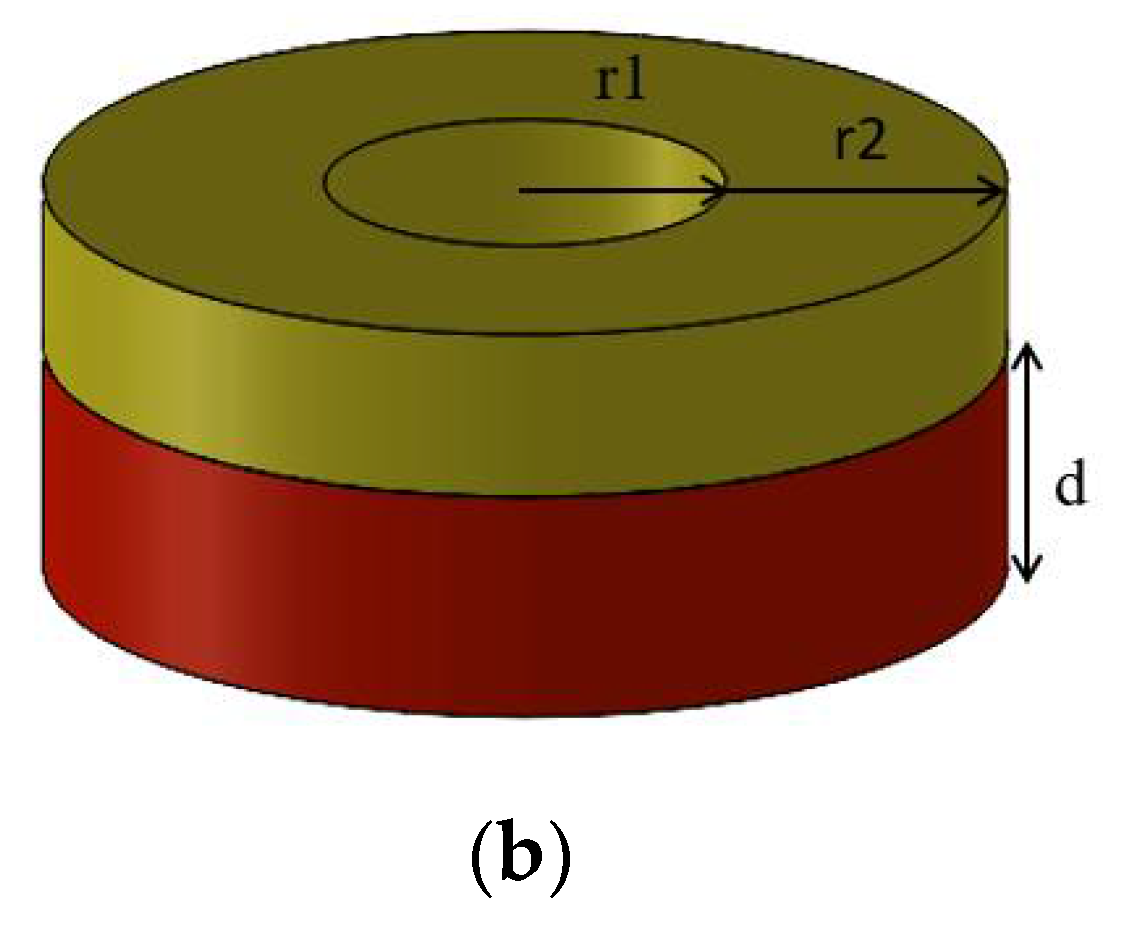
The integrated system consists of three parts: the 5-MW NREL wind turbine [35], a braceless semisubmersible platform [36,37], and a torus-shaped wave energy converter (WEC). The main parameters of the combined structure are shown in Table 1. In the following chapters, the WEC shape is optimized to obtain the final WEC model (Figure 1b), and Table 1 shows the parameters of the optimized WEC. The WEC is located in the middle column of the platform and is connected to the floating platform through a PTO system to capture wave energy. A guide pulley device is arranged between the platform and the WEC to ensure the WEC’s heave motion and reduce friction (Figure 2). A conceptual diagram of the combined system is shown in Figure 1a.
In this study, the hydrodynamic model of the semisubmersible platform and WEC was established based on ANSYS/AQWA [38] (Figure 3). The time-domain dynamic simulation of the integrated system (5 MW wind turbine, semisubmersible platform, WEC) was based on F2A [39] (an open-source, fully coupled analysis code). The PTO system (Figure 2) is implemented by establishing a Fender model in ANSYS/AQWA, which is a simplified linear spring and a linear damper. Wave energy is captured by the relative heaving motion of the semisubmersible platform and the WEC.
In the following section, Section 4.1 is the dimensionless calculation of WEC, Section 4.2 is the frequency domain response study of different WEC, Section 4.3 is the geometric optimization of WEC, Section 4.4 is the viscous damping correction of WEC, and Section 4.5 is the time domain and statistical response study of the integrated system.

4. Results and Discussion

4.1. Dimensionless Calculation

In this paper, the draft d of WEC is taken as a dimensionless parameter, and the related geometric parameters and hydrodynamic coefficients of WEC are dimensionlessly processed. The dimensionless size d s , dimensionless mass m ¯ and dimensionless hydrostatic stiffness K ¯ are expressed as:
d s = 2 r 2 2 r 1 2 d m ¯ = m ρ π ( r 2 2 r 1 2 ) d = 1 K ¯ = K ρ g π ( r 2 2 r 1 2 ) = 1
The dimensionless natural frequency ω ¯ is expressed as:
ω ¯ = ω g / d
The dimensionless added mass a m ¯ , radiation damping r d ¯ , and wave excitation force F e x ¯ are expressed as:
a m ¯ = a m ρ π ( r 2 2 r 1 2 ) d r d ¯ = r d ρ π ( r 2 2 r 1 2 ) g d F e x ¯ = F e x ρ g π ( r 2 2 r 1 2 ) d
where g = 9.81 m/s2 is the acceleration of gravity.
If the inner and outer radius and the draught of the WEC are given, the dimensionless size d s can be calculated. For a given d s , the dimensionless natural frequency and the dimensionless added mass have the following relationship:
ω ¯ ( 2 r 2 2 r 1 2 / d ) = 1 1 + a m ¯ ( ω ¯ ( 2 r 2 2 r 1 2 / d ) )
In the WEC design principle, when the WEC heave’s natural frequency is equal to the wave frequency, then resonance might occur, which leads to a larger heave amplitude to achieve the purpose of capturing more wave energy. Therefore, the WEC draft d is estimated by Equation (18) for a given dimensionless size d s that is determined according to the given typical average wave frequency ω t
d = g ( ω ¯ ( 2 r 2 2 r 1 2 / d ) ω t ) 2
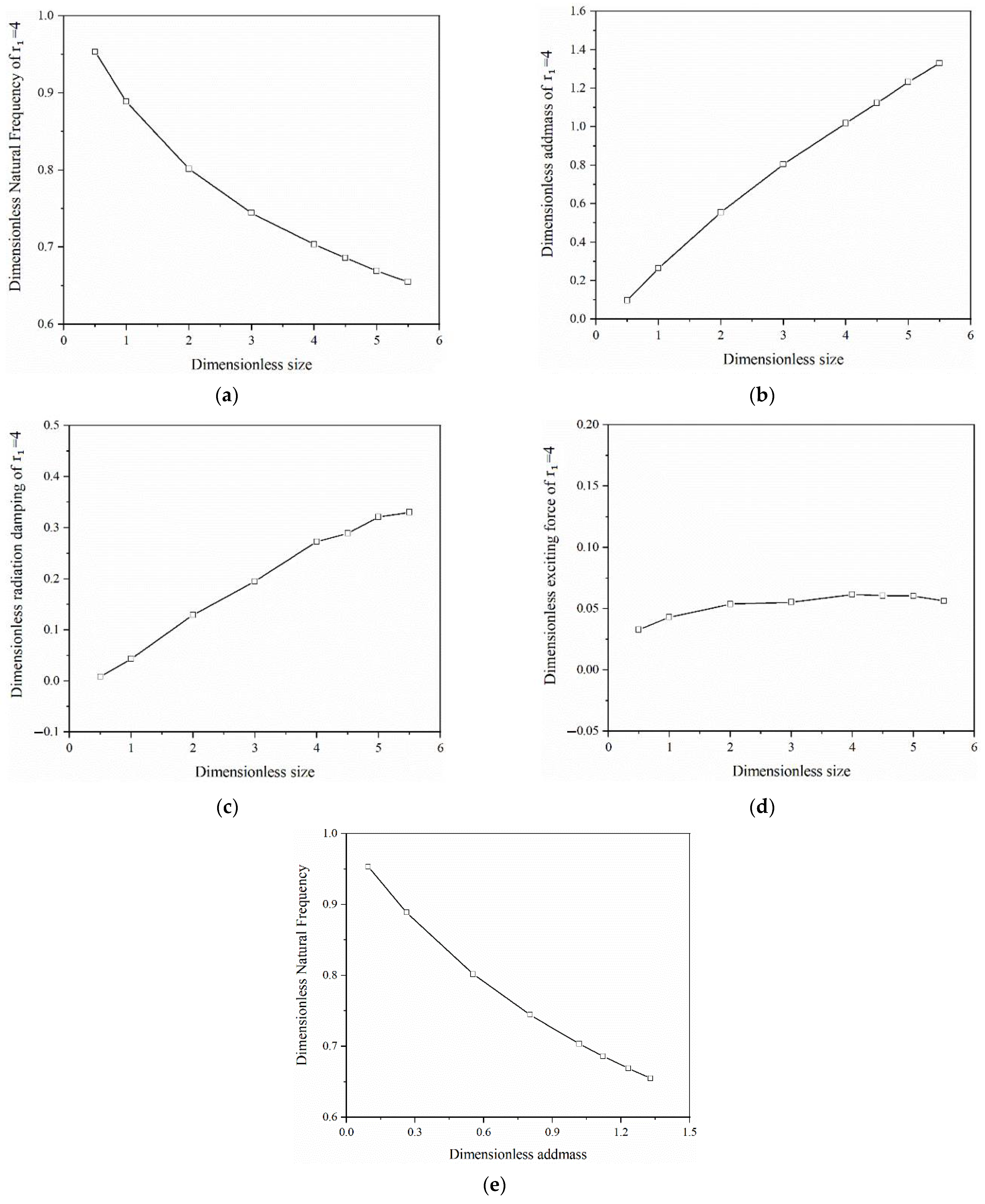
Figure 4 shows the variation of the WEC dimensionless parameters of natural frequency, added mass, radiation damping, and wave excitation force along with ds for the condition of r1 = 4 m. It can be seen that the dimensionless added mass (Figure 4a) and radiation damping (Figure 4b) curves basically show a linear increase as the dimensionless size increases, while the dimensionless wave excitation force does not change significantly.
To verify this relationship, five groups of different inner radii were taken at the same time to study the relationship between ds, dimensionless natural frequency, and added mass under different inner radii. As shown in Figure 5, the dimensionless natural frequency and added mass under different inner radii, show good consistency, which verifies this dimensionless process.
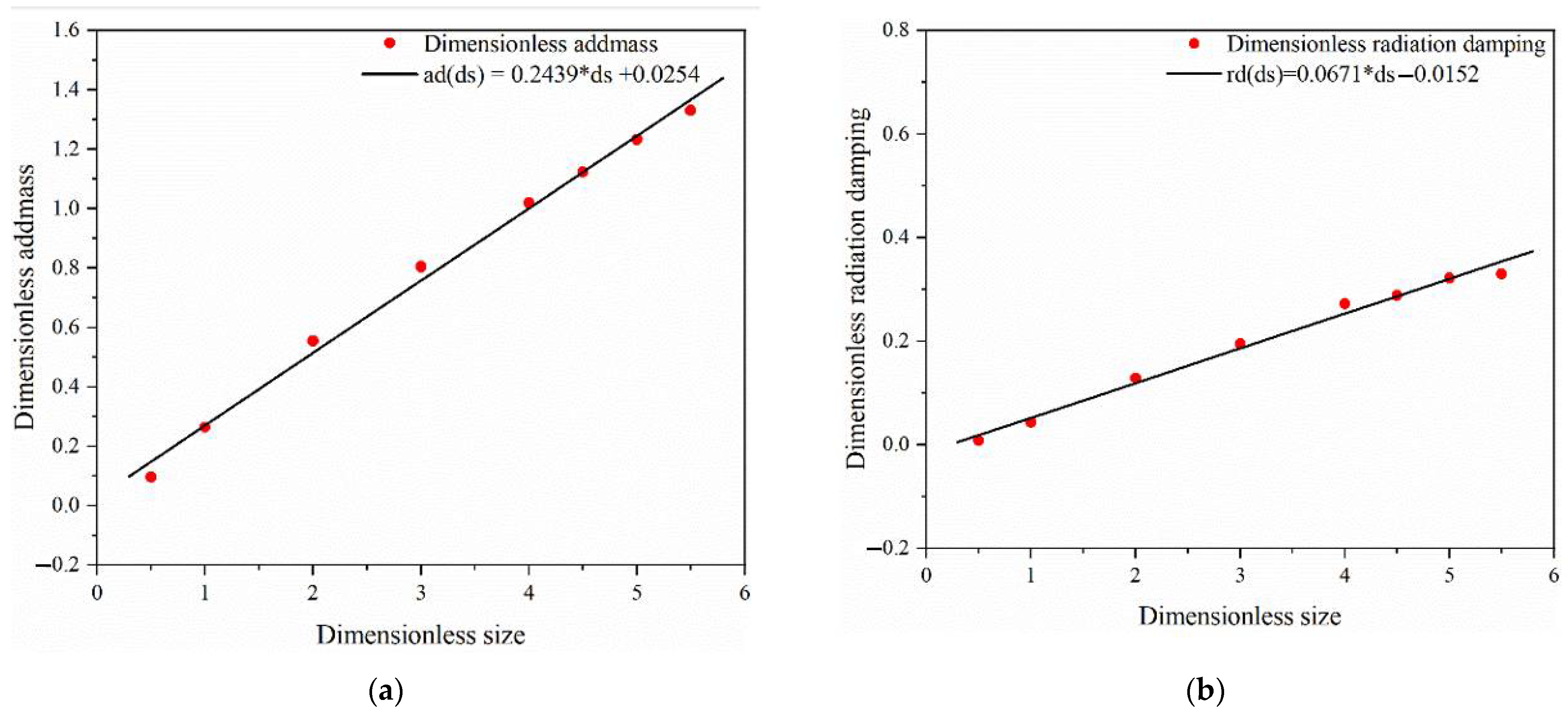
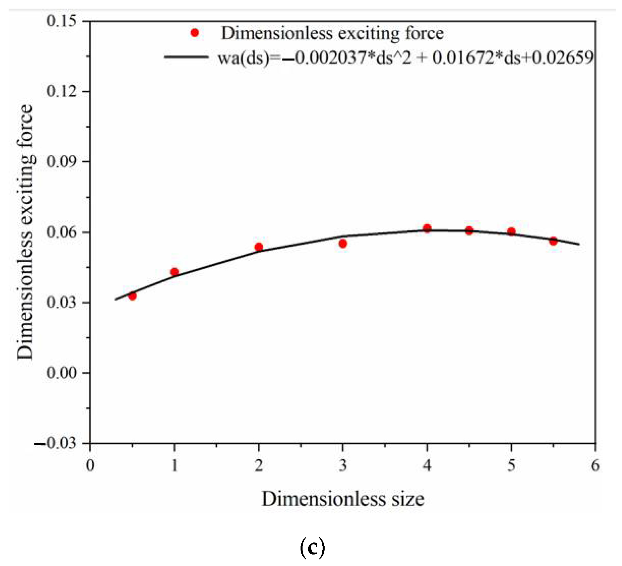
In the paper, the above-established dimensionless relationships are fitted by mathematical expressions, which are illustrated in Figure 6. The linear relationship is fitted for the significantly increased dimensionless added mass and radiation damping, while the wave excitation force fits a quadratic polynomial due to the small change. The value of dimensionless size ds determines the outer radius and draft of WEC, which cannot be too large or too small in practice, so the range of dimensionless size ds 1–6 is reasonable.

4.2. Frequency Domain Response of WEC

In the present paper, the response characteristics of WEC in the frequency domain with different geometric shapes are studied. The WEC geometric properties involve three variables: the inner radius r1, the outer radius r2, and the draft d, as illustrated in Figure 1b.
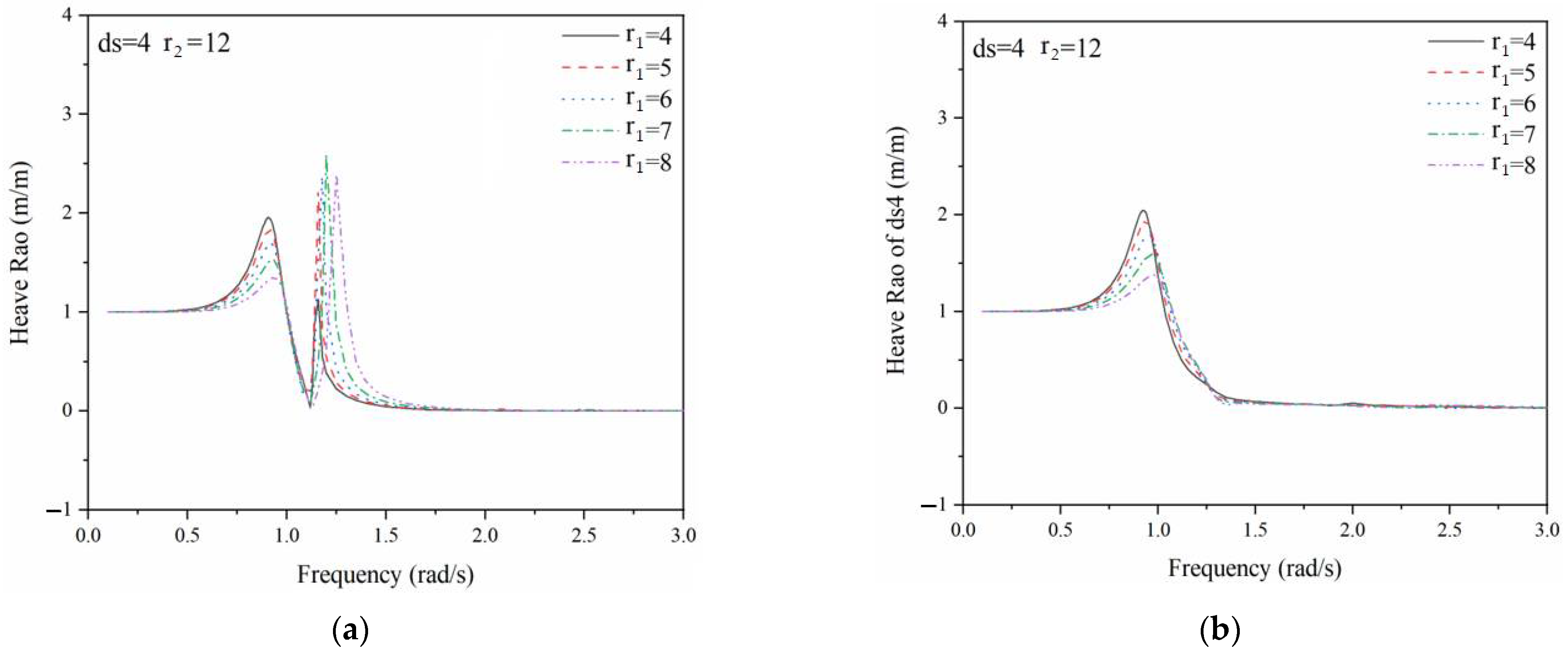
First, the RAOs in heave with different inner radius (r1) are studied for a constant outer radius (r2 = 12) and a given dimensionless size (ds = 4). The results are shown in Figure 7a. Two peaks at approximately 0.8 rad/s and 1.2 rad/s are observed, where the first peak is the natural frequency of WEC and corresponds to a different inner radius (r1). The peak amplitude of the heave RAO at the natural frequency gradually decreases as the r1 increases, while the natural frequency value shifts to the right and increases slowly. The second peak is the resonance of the water caused by the entry and exit of the hollow cylinder, resulting in the moonpool effect [40]. The moonpool effect is eliminated by adding the lid treatment in the numerical analysis; WEC is a hollow structure, and the hydrodynamic calculation unit is defined at the waterplane of the hollow structure to achieve the effect of inhibiting water resonance, as shown in Figure 7b.
In addition, the heave RAO response under different dimensionless size ds is studied under the unchanged inner radius r1 and outer radius r2, which is illustrated in Figure 8. It is seen that the amplitude response of heave RAO increases significantly as the ds decreases. A smaller ds equals to the effect of a larger draft, which has a positive effect on the heave RAO of WEC. However, the WEC will be combined with a semi-submersible platform in practical application, where a large draft will restrain the relative motion of multiple bodies.

4.3. WEC Geometry Optimization

Differential evolution (DE) is commonly used to solve real optimization problems. This algorithm is a kind of adaptive global optimization algorithm based on population and belongs to the evolutionary algorithm. It is widely used because of its simple structure, easy implementation, fast convergence, and strong robustness.
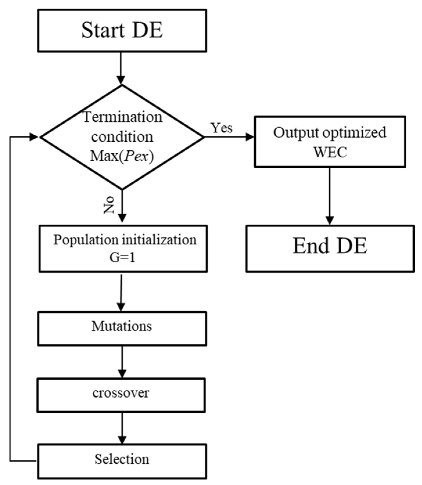
In this paper, the geometric shape of WEC is optimized by using the DE algorithm. The specific process is shown in Figure 9.
(1) Population initialization: initialize the variables in the population and set boundary conditions. In the WECs population of N p individuals (Equation (19)), the initial value of the i-th individual WEC dimensionless size d s i ( 1 ) is shown in Equation (20):
d s ( G ) = { d s 1 ( G ) , d s 2 ( G ) , , d s N P ( G ) }
d s i ( 1 ) = d s min + r a n d ( N p , D ) · ( d s max d s min ) i = 1 , 2 , , N p
where G is the number of population generations, and the value is 100; the population size N p is taken as 10 because the value should be greater than or equal to 4 and is usually taken between 5D and 10D; D is the number of optimization parameters, which is 1 because only one variable ds needs to be optimized in this paper. r a n d ( N p , D ) represents the generated random values of the initial population in row N p and column D; the boundary range of ds is between 2 and 10, because the value should not be too large or too small, otherwise the outer radius and draft of WEC will be too large or too small and that is not advisable.
(2) Population mutation: in this step, the mutant population V i j ( G + 1 ) is obtained, and the mutant individuals N p are randomly generated based on the individuals in the G generation population, as shown:
V i j ( G + 1 ) = d s p ( G ) + M u ( d s j ( G ) d s k ( G ) ) p j k i
where M u is the variation scaling factor. A better algorithm can be searched locally with a smaller M u . Simultaneously, a better algorithm can be jumped out of the local minimum with a larger M u , but the convergence speed will be slower. M u also affects the diversity of populations, which is generally taken between 0 and 2 and the value of 0.6 is used in this work.
(3) Crossover operation: crossover individual U i j ( G + 1 ) is obtained by exchanging mutant individual V i j ( G + 1 ) and target individual X i j ( G ) , as expressed in the following equation:
U i j ( G + 1 ) = { V i j ( G + 1 ) , r a n d C R j = = r a n d ( 1 ) X i j ( G ) , o t h e r w i s e
where C R is the crossover probability, which reflects the extent of the amount of information exchanged between the offspring and the parent as well as intermediate variants during the crossover process. The extent in relation to the information exchange will be greater with the larger value of C R . Conversely, the diversity of the population will decrease rapidly when the value of C R is too small, which is not conducive to global optimization. The value of C R is generally taken between 0 and 1. The value of 0.5 is used in this work.
(4) Selection operation: whether the output power is the maximum wave energy capture power is judged by comparing the objective function value Pex of the crossed individual U i j ( G + 1 ) and the initial target individual X i j ( G ) one-to-one. X i j ( G + 1 ) is the individual with the largest wave energy capture power in the current G generation.
X i j ( G + 1 ) = { U i j ( G + 1 ) , P e x ( U i j ( G + 1 ) ) > P e x ( X i j ( G ) ) X i j ( G ) , o t h e r w i s e
In this paper, the average wave period Tt = 6 s (ωt = 1.047 rad/s) of a typical WEC function is selected. The geometry of WEC is optimized. WEC is suitable for working under high-frequency wave conditions because of its characteristics of small size and large natural frequency. The resonance of the WEC might occur when its natural frequency of WEC is close to the incident wave frequency, which will lead to a better wave energy capture effect. Based on the DE algorithm, the power produced by the globally optimized WEC in the 100-generation population is calculated (Figure 8). When the dimensionless size ds = 3.784, the maximum power captured by the global wave energy is realized, which reaches 93.846 kW. The draft and outer radius of the WEC are 4.6 m and 9.6 m (Figure 10), respectively, when the ds is optimum.
Then, the optimized WEC is combined with the semi-submersible wind turbine to form an integrated system, which is used in the results and discussions in the following sections.

4.4. Viscous Damping Correction of WEC

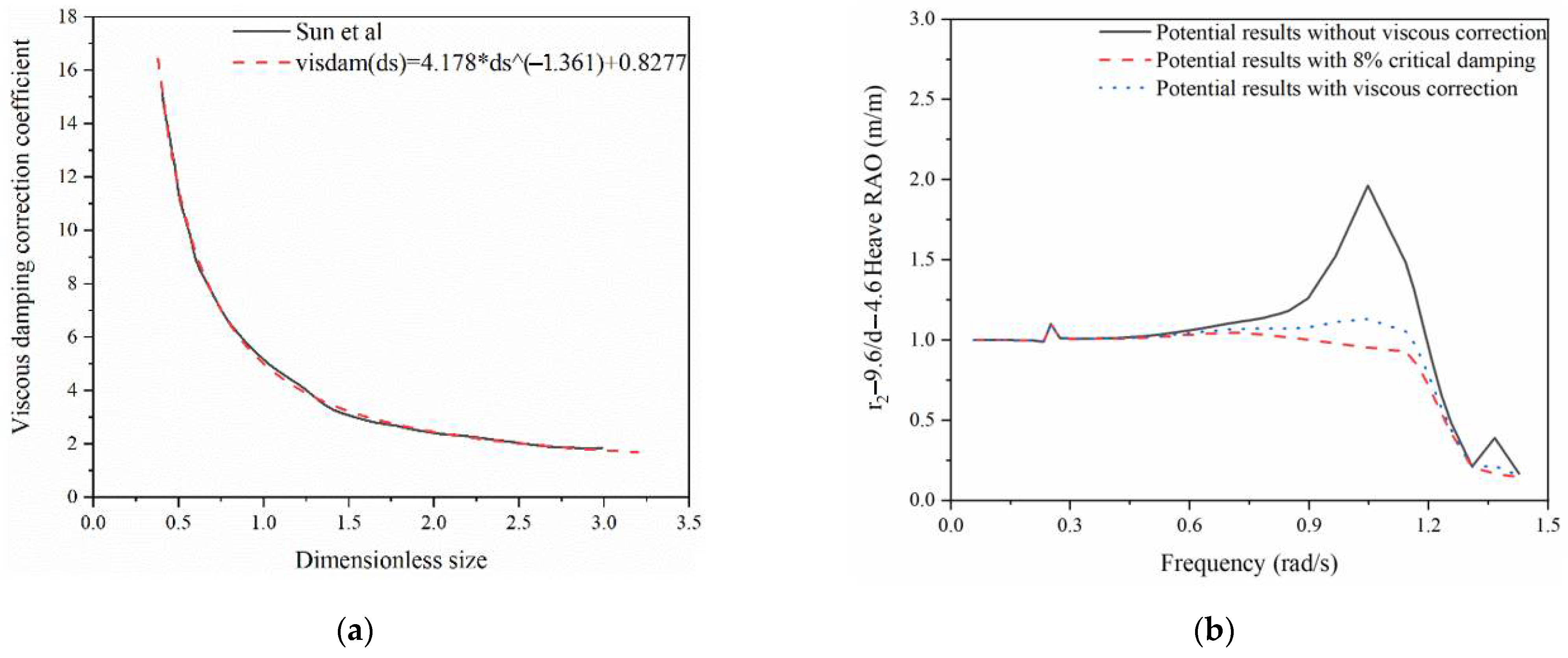
In this paper, a correction and a supplement are considered for the shear viscous damping of WEC. Sun et al. [19] studied the dynamic behavior of the cylindrical wave energy floater under various viscous damping correction conditions and obtained the viscous damping correction coefficient curve. Then, in this work, the viscous damping correction coefficient curve is realized by a mathematical expression that is obtained by data fitting, as illustrated in Figure 11a, and the expression is further used to correct and supplement the WEC viscous damping. In the previous section, the dimensionless size ds of the optimized WEC was chosen as 3.784, and correspondingly, the calculated viscous damping correction coefficient was 1.508. There is a good fit between the mathematical formula and the empirical curve, and the relation between the viscous damping correction coefficient and the dimensionless size is inversely proportional. With the increase in the dimensionless size, the viscous damping coefficient decreases slowly and approaches 1. In other words, the larger the dimensionless size is, the less obvious the viscous damping effect is.
The heave RAO responses between three potential calculations—without viscous correction, with 8% critical damping, and with viscous correction—are compared in Figure 11b. It is seen that the amplitude of the potential flow result without viscous damping is the largest among the three responses at the WEC natural frequency. The potential flow result with an 8% critical damping correction is slightly underestimated compared to those with the viscous damping coefficient correction; the critical damping correction is used in the following section to make the results a bit conservative.

4.5. Comparison of Time Domain and Statistical Responses of Integrated System

The optimal PTO damping of WEC is calculated by Equation (10). In this paper, the dynamic characteristics of the WEC-wind turbine integrated system, considering the optimal WEC PTO damping, are studied. The optimal PTO damping for the WEC is calculated to be 7.81 × 10⁵ N·s/m. The outer radius, inner radius, and WEC PTO damping of the WEC are taken as 8 m. 4 m, and 1.5 × 10⁶ N·s/m, respectively, which are determined based on the previous study [17] that investigated the dynamic characteristics of the integrated system under different combined wind and wave conditions.
Four WEC-wind turbine designs with different WEC geometries and damping are used to study the power characteristics of the integrated system. The main characteristics of the four examined designs are tabulated in Table 2 and explained as follows: (a) Design D1 (WEC without shape optimization): the outer radius is 8 m, the inner radius is 4 m, and the draft is 3.5 m. In addition, a critical damping of 8 % is supplemented to correct the viscous damping, which leads to the WEC PTO damping of 1.5 × 10⁶ N·s/m. (b) design D2 (WEC with shape optimization): the outer radius is 9.6 m, the inner radius is 4 m, and the draft is 4.6 m. Similar to the D1, 8% critical damping is added to correct the viscous damping, and the WEC PTO damping is 1.5 × 10⁶ N·s/m, (c) design D3 (WEC without shape optimization; same shape as in D2): a correction coefficient of 1.508 is supplemented to the viscous damping, and the WEC PTO damping is 1.5 × 10⁶ N·s/m. (d) Design D4 (WEC without shape optimization; same shape as in D2): the optimal WEC PTO damping is 7.81 × 10⁵ N·s/m.
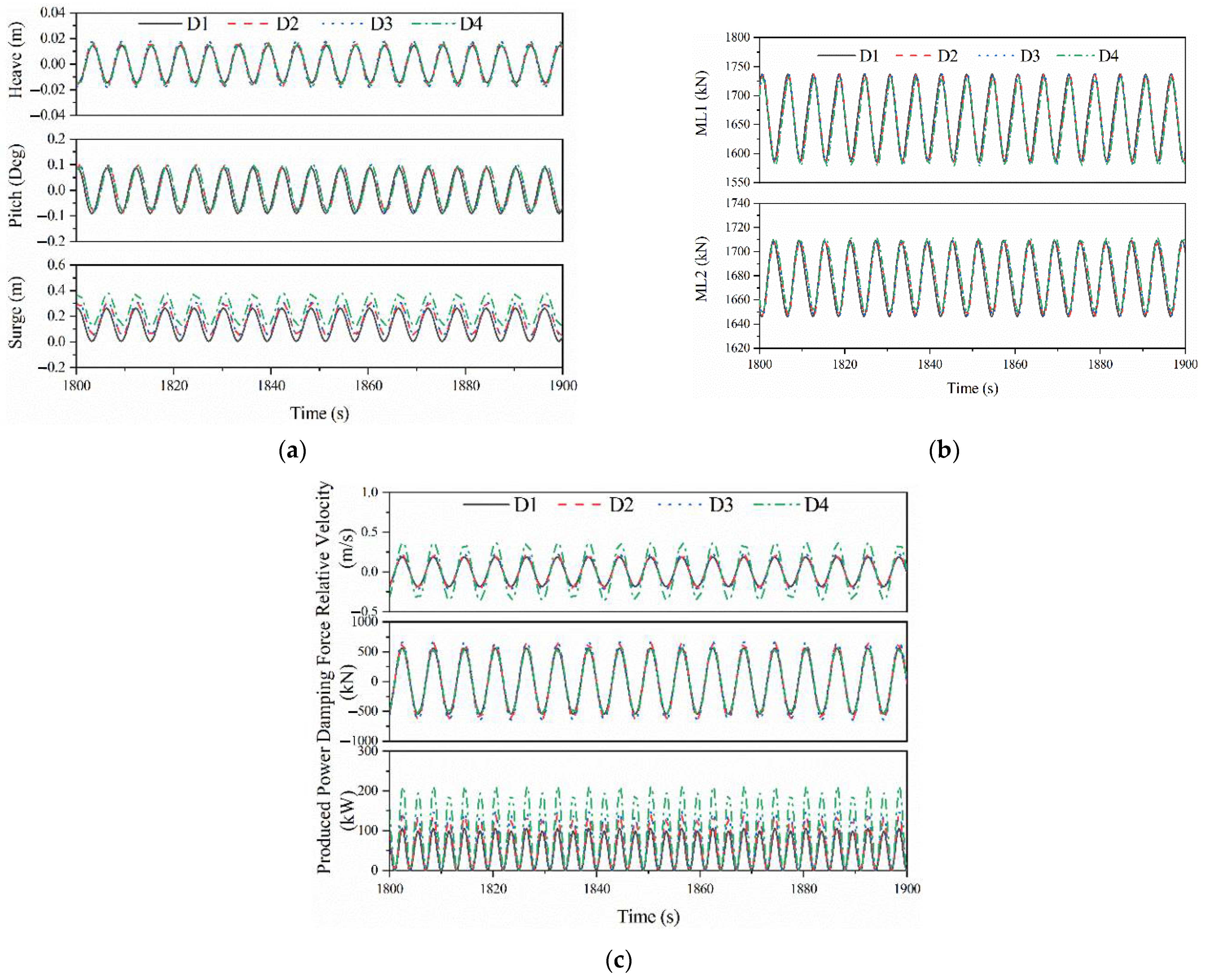
Figure 12 compares the time domain responses of the four different integrated models under the regular wave condition with wave period T = 6 s and wave height H = 2 m; The dynamic responses of the platform motions, mooring line forces, and power generation between the four designs are compared. Each simulation lasts for 4100 s and the first 500 s has been removed to avoid the start-up effect. The responses in the time series range of 1800–1900 s are presented to clearly illustrate the comparisons. The comparisons between the responses of D1 and the other three models indicate that the WEC shape optimization does not influence the pitch and surge motions, but increases the heave motions significantly. The dynamic responses of the mooring line tensions between the four design models are very close, which means that the WEC shape optimization and the PTO damping do not influence the mooring line load effects. As seen from Figure 12c, the relative heave velocity amplitude of the D4 of the integrated system increases significantly, which is due to the change of the WEC PTO damping that reduces the weakening effect of the heave velocity. The heave damping force amplitudes of the D2 and D3 models are slightly larger than those of D1 and D4 models, but the responses between these four design models are generally very close. As the critical response the mean wave energy capture power of the D2 is approximately 67.08 Kw when the WEC shape is optimized, which is significantly higher than the 50.81 Kw produced in D1 model without the WEC shape optimization. The mean captured powers of the D2 and D3 models are 67.08 Kw and 71.03 Kw, respectively, which are very close. This means that the different viscous damping corrections have negligible influence on the power performance of the WEC-wind turbine integrated system. The mean captured power is approximately 101.4 Kw of the D4 model that employs the optimal PTO damping, and the captured power is significantly higher than the 71.03 Kw of the D3 model in which a different PTO damping is considered.
Figure 13 compares the statistical responses of the four different models, including max, min, mean and standard deviation. The statistical values of the mooring line tension between the four design models are very close. The mean value of the mooring line 2 (ML2) tension of the design model D4 is 0.27% higher than that of the model D1 because of the optimization of the WEC shape. The maximum value of the relative heave velocity (WEC and platform heave velocity difference) of the integrated system D2 with the WEC shape optimization increased by 15.24% compared to that of the D1 without the WEC shape optimization. The maximum value of the relative heave velocity of the final optimized integrated system (D4) is increased by 96.73% compared to that of the D1 that does not consider the optimization. The maximum value of the vertical damping force of the final optimized integrated system (D4) is increased by 2.34% compared to that of the D1 without the optimization, while the difference in the statistical responses of the damping forces between the four models is very small. The average energy capture power of the integrated system (D2) with the WEC shape optimization is increased by 32.03% compared to that of the D1 without the WEC shape optimization. In addition, compared to the mean value of the captured power of the integrated system D2, an increase of approximately 5.89% is obtained in the model D3 where the viscous damping coefficient is employed. The mean value of the produced power is increased by 42.75% in the integrated system D3 compared to that in the D2, which is due to the change of the WEC optimal PTO damping in the D3. Considering the WEC shape optimization and the optimal PTO damping of 7.81 × 10⁵ N·s/m, a significant increase in the produced power is realized in D4; specifically, the mean power production in D4 is almost double of that in D1 without the shape optimization. This implies that optimizing the WEC shape and PTO damping are effective solutions to improve the energy capture of the wave energy converter and thus to increase the power production.

5. Concluding Remarks

This paper deals with the study of the dynamic power and load effect performance of an integrated wind–wave energy system using an optimized hollow cylinder wave energy converter (WEC). A numerical model consisting of a 5-MW semisubmersible wind turbine with an optimized WEC is established using the open-source code F2A. The hydrodynamic loads on the integrated platform are calculated based on the potential flow theory by using the hydrodynamic code AQWA. A dimensionless optimization method is developed and used for the shape optimization of the WECs, and the differential evolution (DE) algorithm is employed to obtain the optimal WEC. The frequency-domain response characteristics of WEC with different geometric shapes and viscous damping corrections are investigated. The time domain and statistical responses of the integrated system with and without the WEC optimization are compared. The main findings and research conclusions are summarized as follows:
(1) A dimensionless method is established to unify the relationship between the hydrodynamic coefficient of the hollow cylindrical WEC and the geometric parameters, and the dimensionless results obtained by the WEC under different inner radius have a good consistency. The dimensionless method proposed in this paper is feasible and suitable for hollow cylindrical WEC.
(2) The frequency domain characteristics of WEC with different inner radius r1 and dimensionless size d s are compared. It is found that the WEC will have a significant moonpool effect, and a smaller inner radius r1 can reduce the moonpool effect; regardless of the moonpool effect, an increase in ds will increase the natural frequency and thus reduce the peak value. A large WEC can significantly increase the heave RAO amplitude. Based on practical considerations, the draft d of the WEC should not be too large; otherwise, it will affect the relative heave motion between the wind turbine and WEC.
(3) The main properties and specifications of the shape-optimum WEC are obtained using the differential evolution algorithm (DE). The capture power is 93.864 kW. The design characteristics of the optimum WEC can be used as a baseline model for public research.
(4) The dynamic characteristics of the mooring lines and heave damping force of the final optimized integrated system (D4) are very close to the integrated system before optimization (D1). The average capture power of the optimum integrated system (D4) is 99.57% higher than that of the previous one without optimization one (D1). Optimization of the WEC shape and WEC PTO damping can significantly increases the power generation produced by the wave energy converter.
Turbine performance issues are very important for the design of OWTs; the proposed generic optimization method will be further expanded in order to include turbine performance issues (e.g., excessive tower motions) in future research work.

Author Contributions

Conceptualization, W.S., J.L., C.M. and X.L.; methodology, W.S., C.M., M.C. and S.W.; investigation, W.S., J.L., S.W. and C.M.; writing—first draft preparation, W.S., J.L. and C.M.; review and editing, W.S., C.M., M.C., S.W. and X.L.; supervision, W.S. and C.M.; project administration, X.L.; funding acquisition, W.S. and X.L. All authors have read and agreed to the published version of the manuscript.

Funding

This research was funded by the National Natural Science Foundation of China (grant No. 52071058, 51939002, 51879040, 52171275). This paper is also partially funded by the Open Research Fund of Hunan Provincial Key Laboratory of Key Technology on Hydropower Development (PKLHD202003).

Institutional Review Board Statement

Not applicable.

Informed Consent Statement

Not applicable.

Data Availability Statement

Not applicable.

Conflicts of Interest

The authors declare no conflict of interest.

References

  1. Zhang, L.; Shi, W.; Zeng, Y.; Michailides, C.; Zheng, S.; Li, Y. Experimental Investigation on the Hydrodynamic Effects of Heave Plates for Application of Floating Offshore Wind Turbine. Ocean Eng. 2023, 267, 113103. [Google Scholar] [CrossRef]
  2. Zhang, Y.; Shi, W.; Li, D.; Li, X.; Duan, Y.; Verma, A.S. A novel framework for modeling floating offshore wind turbines based on the vector form intrinsic finite element (VFIFE) method. Ocean Eng. 2022, 262, 112221. [Google Scholar] [CrossRef]
  3. Shi, W.; Zeng, X.; Feng, X.; Shao, Y.; Li, X. Numerical study of higher-harmonic wave loads and runup on monopiles with and without ice-breaking cones based on a phase-inversion method. Ocean Eng. 2023, 267, 113221. [Google Scholar] [CrossRef]
  4. Cai, Y.; Zhao, H.; Li, X.; Liu, Y. Effects of yawed inflow and blade-tower interaction on the aerodynamic and wake characteristics of a horizontal-axis wind turbine. Energy 2023, 264, 126246. [Google Scholar] [CrossRef]
  5. Shi, W.; Zhang, L.; Karimirad, M.; Michailides, C.; Jiang, Z.; Li, X. Combined effects of aerodynamic and second-order hydrodynamic loads for three semisubmersible floating wind turbines in different water depths. Appl. Ocean Res. 2023, 130, 103416. [Google Scholar] [CrossRef]
  6. Astariz, S.; Iglesias, G. Selecting optimum locations for co-located wave and wind energy farms. Part II: A case study. Energ. Convers. Manag. 2016, 122, 599–608. [Google Scholar] [CrossRef] [Green Version]
  7. Pérez-Collazo, C.; Greaves, D.; Iglesias, G. A review of combined wave and offshore wind energy. Renew. Sustain. Energy Rev. 2015, 42, 141–153. [Google Scholar] [CrossRef] [Green Version]
  8. Peiffer, A.; Roddier, D.; Aubault, A. Design of a point absorber inside the WindFloat structure. In Proceedings of the International Conference on Offshore Mechanics and Arctic Engineering, Rotterdam, The Netherlands, 19–24 June 2011; pp. 247–255. [Google Scholar]
  9. Aubault, A.; Alves, M.; Sarmento, A.N.; Roddier, D.; Peiffer, A. Modeling of an oscillating water column on the floating foundation WindFloat. In Proceedings of the International Conference on Offshore Mechanics and Arctic Engineering, Rotterdam, The Netherlands, 19–24 June 2011; pp. 235–246. [Google Scholar]
  10. Muliawan, M.J.; Karimirad, M.; Moan, T. Dynamic response and power performance of a combined spar-type floating wind turbine and coaxial floating wave energy converter. Renew. Energ. 2013, 50, 47–57. [Google Scholar] [CrossRef]
  11. Chen, M.; Wang, R.; Xiao, P.; Zhu, L.; Li, F.; Sun, L. Numerical analysis of a floating semi-submersible wind turbine integrated with a point absorber wave energy convertor. In Proceedings of the 30th International Ocean and Polar Engineering Conference: OnePetro, Shanghai, China, 11–16 October 2020. [Google Scholar]
  12. Wan, L.; Gao, Z.; Moan, T. Experimental and numerical study of hydrodynamic responses of a combined wind and wave energy converter concept in survival modes. Coast Eng. 2015, 104, 151–169. [Google Scholar] [CrossRef] [Green Version]
  13. Wan, L.; Gao, Z.; Moan, T.; Lugni, C. Comparative experimental study of the survivability of a combined wind and wave energy converter in two testing facilities. Ocean Eng. 2016, 111, 82–94. [Google Scholar] [CrossRef]
  14. Michailides, C.; Gao, Z.; Moan, T. Experimental study of the functionality of a semisubmersible wind turbine combined with flap-type Wave Energy Converters. Renew. Energ. 2016, 93, 675–690. [Google Scholar] [CrossRef]
  15. Wang, Y.; Zhang, L.; Michailides, C.; Wan, L.; Shi, W. Hydrodynamic Response of a Combined Wind–Wave Marine Energy Structure. J. Mar. Sci. Eng. 2020, 8, 253. [Google Scholar] [CrossRef] [Green Version]
  16. Wang, Y.; Shi, W.; Michailides, C.; Wan, L.; Kim, H.; Li, X. WEC shape effect on the motion response and power performance of a combined wind-wave energy converter. Ocean Eng. 2022, 250, 111038. [Google Scholar] [CrossRef]
  17. Li, J.; Shi, W.; Zhang, L.; Michailides, C.; Li, X. Wind–Wave Coupling Effect on the Dynamic Response of a Combined Wind–Wave Energy Converter. J. Mar. Sci. Eng. 2021, 9, 1101. [Google Scholar] [CrossRef]
  18. Hu, J.; Zhou, B.; Vogel, C.; Liu, P.; Willden, R.; Sun, K.; Zang, J.; Geng, J.; Jin, P.; Cui, L. Optimal design and performance analysis of a hybrid system combing a floating wind platform and wave energy converters. Appl. Energ. 2020, 269, 114998. [Google Scholar] [CrossRef]
  19. Sun, K.; Xie, G.; Zhou, B. Type selection and hydrodynamic performance analysis of wave energy converters. J. Harbin Eng. Univ. 2021, 42, 8–14. [Google Scholar]
  20. Zou, M.; Chen, M.; Zhu, L.; Li, L.; Zhao, W. A constant parameter time domain model for dynamic modelling of multi-body system with strong hydrodynamic interactions. Ocean Eng. 2023, 268, 113376. [Google Scholar] [CrossRef]
  21. Zhang, W.; Liu, H.; Zhang, L.; Zhang, X. Hydrodynamic analysis and shape optimization for vertical axisymmetric wave energy converters. China Ocean Eng. 2016, 30, 954–966. [Google Scholar] [CrossRef]
  22. Chen, M.; Xiao, P.; Zhang, Z.; Sun, L.; Li, F. Effects of the end-stop mechanism on the nonlinear dynamics and power generation of a point absorber in regular waves. Ocean Eng. 2021, 242, 110123. [Google Scholar] [CrossRef]
  23. Chen, M.; Xiao, P.; Zhou, H.; Li, C.B.; Zhang, X. Fully Coupled Analysis of an Integrated Floating Wind-Wave Power Generation Platform in Operational Sea-states. Front. Energy Res. 2022, 10, 819. [Google Scholar] [CrossRef]
  24. Pastor, J.; Liu, Y. Power absorption modeling and optimization of a point absorbing wave energy converter using numerical method. J. Energy Resour. Technol. 2014, 136, 021207. [Google Scholar] [CrossRef]
  25. Blanco, M.; Lafoz, M.; Ramirez, D.; Navarro, G.; Torres, J.; Garcia-Tabares, L. Dimensioning of point absorbers for wave energy conversion by means of differential evolutionary algorithms. IEEE Trans. Sustain. Energ. 2018, 10, 1076–1085. [Google Scholar] [CrossRef]
  26. Wang, L.; Engström, J.; Göteman, M.; Isberg, J. Constrained optimal control of a point absorber wave energy converter with linear generator. J. Renew. Sustain. Energy 2015, 7, 043127. [Google Scholar] [CrossRef]
  27. Storn, R.; Price, K. Differential evolution—A simple and efficient heuristic for global optimization over continuous spaces. J. Glob. Optim. 1997, 11, 341–359. [Google Scholar] [CrossRef]
  28. Lyu, J.; Abdelkhalik, O.; Gauchia, L. Optimization of dimensions and layout of an array of wave energy converters. Ocean Eng. 2019, 192, 106543. [Google Scholar] [CrossRef]
  29. Vesterstrom, J.; Thomsen, R. A comparative study of differential evolution, particle swarm optimization, and evolutionary algorithms on numerical benchmark problems. In Proceedings of the 2004 Congress on Evolutionary Computation (IEEE Cat. No. 04TH8753), Portland, OR, USA, 19–23 June 2004; pp. 1980–1987. [Google Scholar]
  30. Fang, H.; Feng, Y.; Li, G. Optimization of wave energy converter arrays by an improved differential evolution algorithm. Energies 2018, 11, 3522. [Google Scholar] [CrossRef] [Green Version]
  31. Faltinsen, O. Sea Loads on Ships and Offshore Structures; Cambridge University Press: Cambridge, UK, 1993. [Google Scholar]
  32. Van Rijn, L.C. Principles of Fluid Flow and Surface Waves in Rivers, Estuaries, Seas and Oceans; Aqua Publications: Amsterdam, The Netherlands, 1990. [Google Scholar]
  33. He, Z.; Ning, D.; Gou, Y.; Zhou, Z. Wave energy converter optimization based on differential evolution algorithm. Energy 2022, 246, 123433. [Google Scholar] [CrossRef]
  34. Ren, Z.; Han, X.; Yu, X.; Skjetne, R.; Leira, B.J.; Sævik, S.; Zhu, M. Data-driven simultaneous identification of the 6DOF dynamic model and wave load for a ship in waves. Mech. Syst. Signal Process. 2023, 184, 109422. [Google Scholar] [CrossRef]
  35. Jonkman, J.; Butterfield, S.; Musial, W.; Scott, G. Definition of A 5-MW Reference Wind Turbine for Offshore System Development; National Renewable Energy Lab (NREL): Golden, CO, USA, 2009. [Google Scholar]
  36. Luan, C.; Gao, Z.; Moan, T. Design and analysis of a braceless steel 5-mw semi-submersible wind turbine. In Proceedings of the International Conference on Offshore Mechanics and Arctic Engineering, Busan, Republic of Korea, 19–24 June 2016; American Society of Mechanical Engineers: New York, NY, USA, 2016; p. V006T09A052. [Google Scholar]
  37. Zhang, L.; Shi, W.; Karimirad, M.; Michailides, C.; Jiang, Z. Second-order hydrodynamic effects on the response of three semisubmersible floating offshore wind turbines. Ocean Eng. 2020, 207, 107371. [Google Scholar] [CrossRef]
  38. ANSYS Inc. AQWA Manual Release 19.0; ANSYS Inc.: Canonsburg, PA, USA, 2018. [Google Scholar]
  39. Yang, Y.; Bashir, M.; Michailides, C.; Li, C.; Wang, J. Development and application of an aero-hydro-servo-elastic coupling framework for analysis of floating offshore wind turbines. Renew. Energ. 2020, 161, 606–625. [Google Scholar] [CrossRef]
  40. Chen, M.; Guo, H.; Wang, R.; Tao, R.; Cheng, N. Effects of gap resonance on the hydrodynamics and dynamics of a multi-module floating system with narrow gaps. J. Mar. Sci. Eng. 2021, 9, 1256. [Google Scholar] [CrossRef]
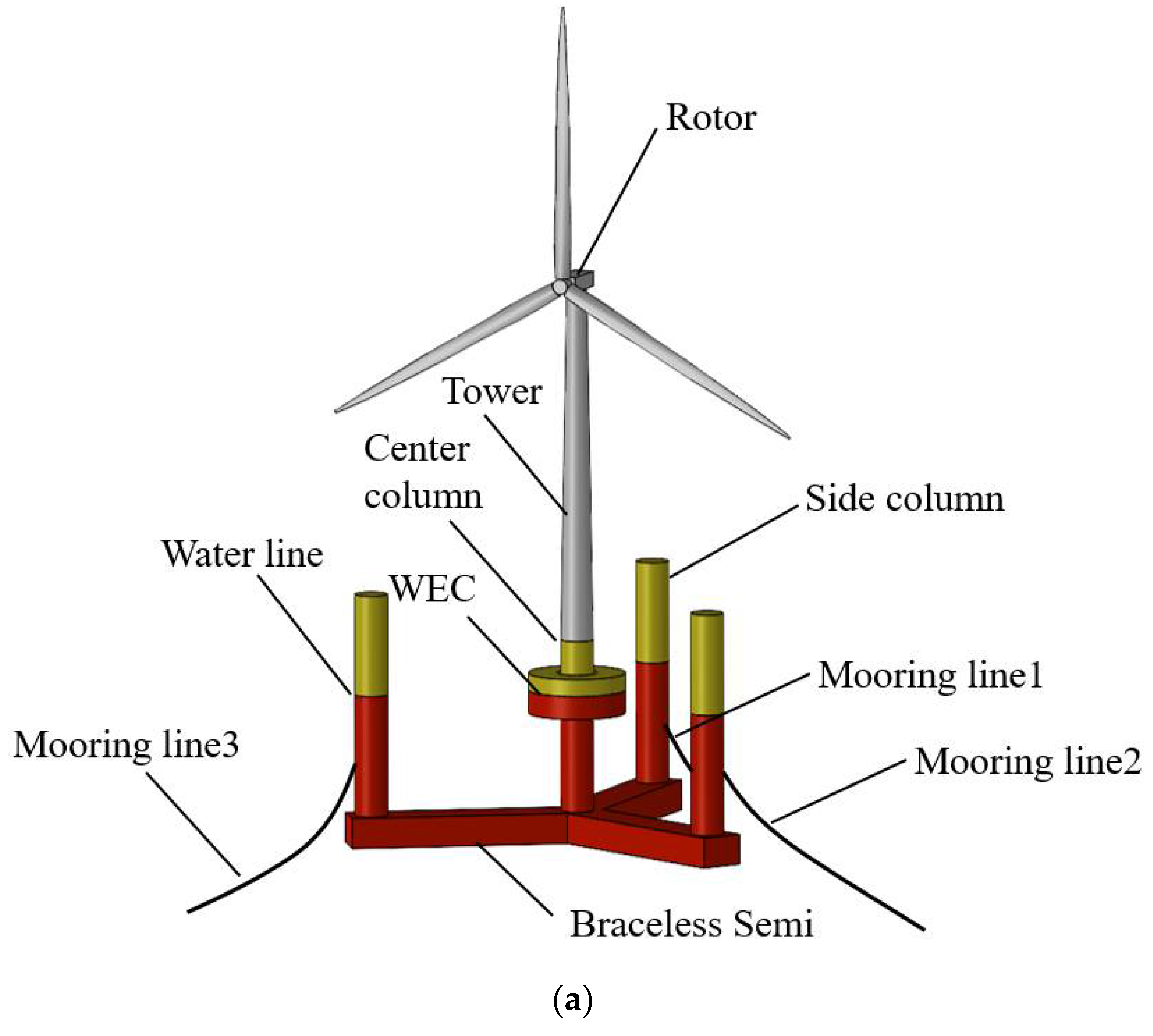
Figure 1. Conceptual diagram of the WEC-wind turbine integrated models. (a) Conceptual diagram of the integrated system. (b) Detailed view of the WEC model.
Jmse 10 01985 g001aJmse 10 01985 g001b
Figure 2. Simplified PTO system between platform and WEC.
Jmse 10 01985 g002
Figure 3. Panel models for the hydrodynamic analysis.
Jmse 10 01985 g003
Figure 4. Variation of WEC dimensionless parameters. (a) Natural frequency. (b) Added mass. (c) Radiation damping. (d) Wave excitation force. (e) Natural frequency-added mass.
Jmse 10 01985 g004
Figure 5. Dimensionless relationship of different inner radius. (a) Natural frequency. (b) Added mass.
Jmse 10 01985 g005
Figure 6. The mathematical expression of dimensionless relation. (a) Added mass. (b) Radiation damping. (c) Wave excitation force.
Jmse 10 01985 g006aJmse 10 01985 g006b
Figure 7. Heave RAO with different inner radius WEC. (a) Heave RAO. (b) Heave RAO after adding a lid.
Jmse 10 01985 g007
Figure 8. Heave RAOs under different ds cases.
Jmse 10 01985 g008
Figure 9. DE algorithm optimization process.
Jmse 10 01985 g009
Figure 10. Variation of power with evolutionary generation G in the optimization process of the DE algorithm.
Jmse 10 01985 g010
Figure 11. Viscous damping correction for WEC. (a) Viscous Damping Correction Mathematical Expression. (b) Heave RAO with different viscous damping corrections.
Jmse 10 01985 g011
Figure 12. The time domain curves of four different integrated systems. (a) Platform Motion. (b) Mooring Lines force. (c) Produced Power characteristic.
Jmse 10 01985 g012
Figure 13. The statistical responses of four different integrated system. (a) Mooring Lines force statistics. (b) Relative heave velocity statistics. (c) Damping force statistics. (d) Produced Power statistics.
Jmse 10 01985 g013
Table 1. The main parameters of the combined system.
Wind Turbine (NREL 5MW)Rotor-Nacelle-Assembly (t)350
Tower mass (t)347.46
Center of Gravity (CoG) (m)(−0.2, 0.0, 70)
Semisubmersible platformSemisubmersible mass (t)9738
Diameter of the central/side column (m)6.5
Water displacement (m3)10,298
Water depth (m)200
Operating draft (m)30
Centre of semisubmersible (m)(0,0, 24.36)
Optimized WECOuter/Inner diameter (m)19.2/8
Height/Draft (m)8/4.6
Mass (t)1128
Water displacement (m3)1100.4
Center of mass (m)(0, 0, −2)
Table 2. The main characteristics of the four designs.
Four DesignsWEC Geometric ParametersViscous Damping CorrectionWEC PTO Damping
D1Outer/Inner radius 8/4 m
draft 3.5 m
8% critical damping1.5 × 106 N·s/m
D2Outer/Inner radius 9.6/4 m
draft 4.6 m
8% critical damping1.5 × 106 N·s/m
D3Outer/Inner radius 9.6/4 m
draft 4.7 m
correction coefficient of 1.5081.5 × 106 N·s/m
D4Outer/Inner radius 9.6/4 m
draft 4.8 m
correction coefficient of 1.5087.81 × 105 N·s/m
Publisher’s Note: MDPI stays neutral with regard to jurisdictional claims in published maps and institutional affiliations.