Article

The POSEIDON Ocean Observing System: Technological Development and Challenges

by
Manolis Ntoumas
1,*,
Leonidas Perivoliotis
2,
George Petihakis
1,
Gerasimos Korres
2,
Constantin Frangoulis
1,
Dionysios Ballas
2,
Paris Pagonis
2,
Maria Sotiropoulou
2,
Manolis Pettas
1,
Evi Bourma
2,
Sylvia Christodoulaki
1,
Dimitris Kassis
2,
Nikos Zisis
2,
Spyros Michelinakis
1,
Dimitra Denaxa
2,
Antigoni Moira
2,
Aspasia Mavroudi
2,
Gerasimi Anastasopoulou
2,
Athanasia Papapostolou
2,
Charikleia Oikonomou
2 and
Natalia Stamataki
1
add Show full author list remove Hide full author list
1
Institute of Oceanography, Hellenic Center for Marine Research, GR-71003 Heraklion, Greece
2
Institute of Oceanography, Hellenic Center for Marine Research, GR-19013 Anavyssos, Greece
*
Author to whom correspondence should be addressed.
J. Mar. Sci. Eng. 2022, 10(12), 1932; https://doi.org/10.3390/jmse10121932
Submission received: 17 October 2022 / Revised: 14 November 2022 / Accepted: 24 November 2022 / Published: 7 December 2022
(This article belongs to the Special Issue Application of Coastal/Ocean Sensors and Systems)

Abstract

:
Advanced marine observation infrastructures are the most significant scientific tool for the study of marine ecosystem trends and shifts. Ocean monitoring technologies, though highly demanding and expensive, are essential for the monitoring and long-term study of oceanic systems. The POSEIDON system for monitoring and forecasting the marine environment is an augmented research infrastructure, unique in the Eastern Mediterranean basin, contributing to the European Ocean Observing System implementation, focusing—among others—on biogeochemical observations and deep-sea ecosystem and geological processes. The technological evolution of the POSEIDON system through a science-coupled strategy supported by engineers and scientists, resulted in a state-of-the-art ocean observing system. There has been a continuous expansion of the infrastructure with new scientific platforms and supporting facilities. Innovative sensing technologies were introduced in the operational data acquisition and new methodologies and tools were developed to improve the system operations and efficiency. As a part of the scientific community of ocean observatories, POSEIDON contributes actively to the improving of the ocean observing. International access to engineering and field demonstrating services, data products and technology testing facilities has been offered to scientists and industry partners. POSEIDON is a widely recognizable international technology testing/demonstrating node specializing in marine technology providing high-level services.

1. Introduction

The European Global Ocean Observing System (EuroGOOS) includes a broad network of organizations and initiatives operating numerous platforms, such as drifting instrumented floats reaching previously unexplored areas (EuroARGO), fixed-point surface and cabled ocean floor observatories providing real-time data from the bottom layer to the surface of the oceans (EMSO), coastal infrastructures to study marine coastal systems and evaluate the combined effects of natural and anthropogenic changes (JERICO) and high-tech autonomous vehicles such as gliders and AUVs (GROOM). The resolution and the data quality of the Essential Ocean Variables (EOVs) is continuously improving, and efforts are made to introduce new biological, genetic and deep-ocean EOVs, together with the Marine Strategy Framework Directive (MSFD) descriptors. Part of this joint international effort is the POSEIDON system (www.poseidon.hcmr.gr, accessed on 5 October 2022) developed in 2000 to fulfil the ambition of an innovative operational oceanography system in the Eastern Mediterranean Sea [1]. The evolution of POSEIDON in compliance to the policy framework suggested by EuroGOOS and Group on Earth Observations (GEO) resulted in an end-to-end operational system covering the full value chain, from observations to data processing and handling and to services with a suite of modelling products. At its initial phase, the POSEIDON observing system consisted of eight moored buoys deployed in the Aegean Sea, while during the first major upgrade (2005–2007 period), three multi-parametric stations were deployed in key positions (Athos basin, Cretan Sea and SE Ionian) for the continuous recording of the water column down to 1000 m. In the following years, the system, in accordance with the global practices, adopted a multiplatform multiparametric strategy with oceanographic buoys network, Argos profiling floats, the ferry–box system, gliders, cabled seabed platform, tide gauges stations and an HF radar network, which are operated and supported by several land base facilities. The POSEIDON system actively contributes to the European Ocean Observing System (EOOS) implementation [2], focuses on biogeochemical (BGC) observations and monitors deep sea ecosystems and geological processes [3,4]. The POSEIDON fixed stations are part of the global network of OceanSITES. At a regional level, the POSEIDON team collaborate with scientists from the multiparametric, ocean buoy network for the Mediterranean basin (W1-M3A, E2-M3A and DYFAMED). Moreover, the Hellenic Centre for Marine Research (HCMR) is participating with the POSEIDON System in the national research infrastructure HIMIOFoTS (The Hellenic Integrated Marine Observing, Forecasting and Technology System) that links together ocean observing and forecasting systems, coastal zone monitoring and management practices, as well as ocean engineering testing facilities [5].
The present work consists of a short description of the observing components of the POSEIDON system, including their operation and challenges, the data return of temperature and salinity timeseries as efficiency indicator for the multiparametric buoys, the tool of the access offered to the POSEIDON nodes. The strategy of its future technological developments and upgrades is also described in terms of national and international policy requirements.

2. The POSEIDON System

The POSEIDON system is supported by a team of researchers, scientists and engineers with different expertise and scientific backgrounds from the Institute of Oceanography (IO) of HCMR. There is a combination of practical science and engineering experience acquired over the years, as well as the addition of new specialized personnel that has supported the POSEIDON multistage development. (Figure 1). The scientific mission and the technological complexity of the current multiplatform observing system proved to be a challenge demanding the cooperation of the different personnel in all activities.

2.1. The Observing System Components

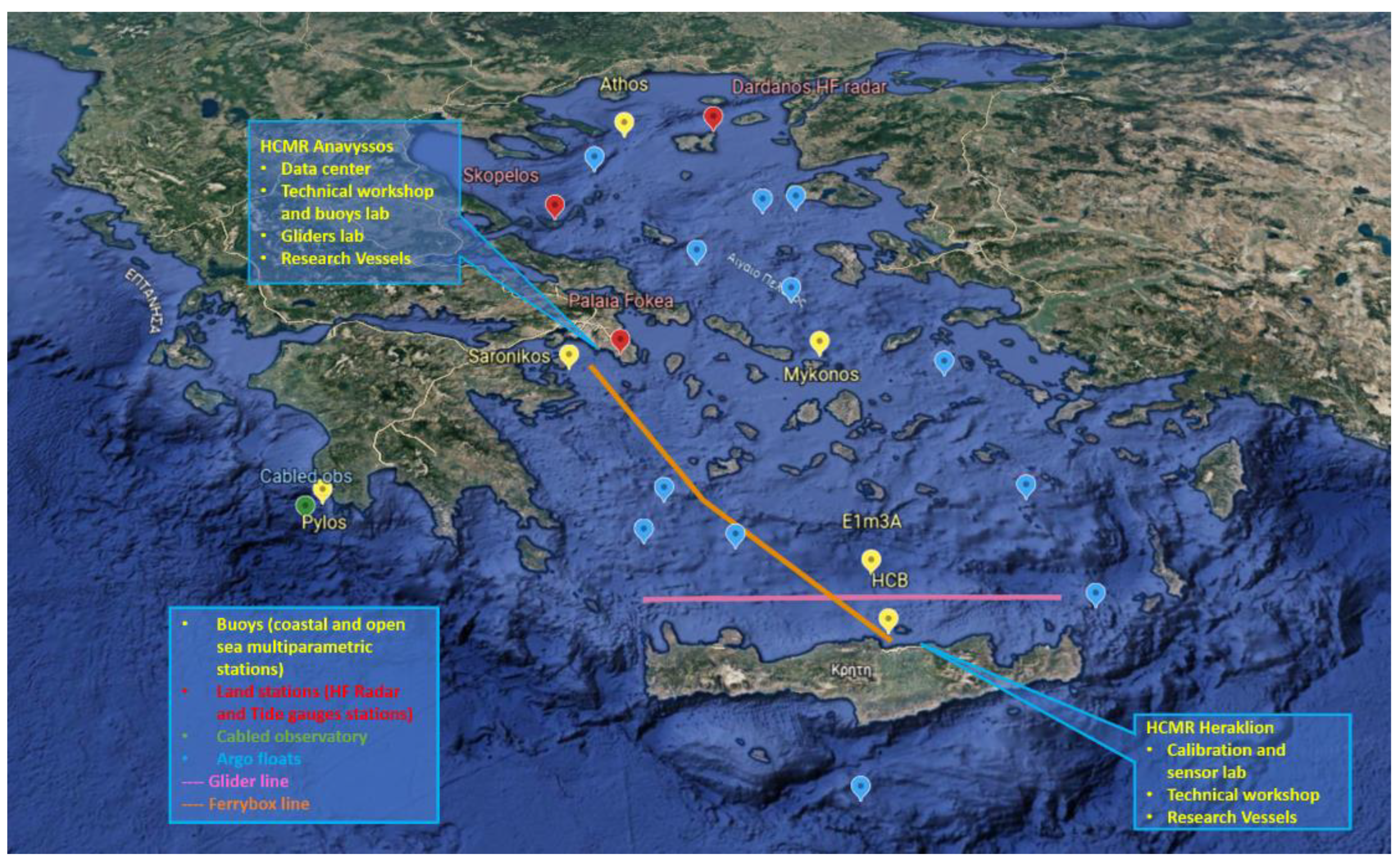
The fixed stations of the POSEIDON system are surface buoys deployed at various coastal and open sea sites in the Aegean and Ionian seas (Figure 2). The locations of the selected stations (Pylos, Athos, Mykonos, Saronikos and Cretan Sea) represent interconnected marine basins with different characteristics and governing processes. The SE Ionian is a crossroad where significant intermediate and deep-water masses meet. In particular, it is on the pathway of the Aegean Sea dense water that travels to the north along the western coast of Greece. Furthermore, it is a very geologically active area with lots of seismic activities and landslides, as well as a potential source of Tsunamis that might affect the Eastern Mediterranean Sea. The Cretan sea is an area of open sea conditions, characterized as extremely oligotrophic where dense waters with intermediate and deep characteristics are formed. A dipole gyre system in combination with the presence of a number of water masses creates a unique ecosystem governed mainly by physical processes.
The network consists of three coastal platforms operating in marine areas shallower than 300 m (SARONIKOS, HERAKLEION, MYKONOS) and three multiparametric off-shore platforms deployed at ~1500 m (E1M3A, PYLOS, ATHOS). Both coastal and open-sea types of floats are manufactured in Norway by Fugro Oceanor. The coastal Seawatch stations can host atmospheric and surface scientific payloads. The multiparametric off-shore Wavescan stations, apart from increased atmospheric and sea surface payloads, are capable of supporting real-time sensors at multiple depths (>1000 m) through inductive coupling telemetry. The data are transmitted in Near Real Time (NRT) to the POSEIDON operational center where they are automatically processed, quality controlled, stored to the system’s database and then released to all major European Marine Data Aggregators (CMEMS, EMODnet etc.)
The Argo Floats are free-drifting floats with automated profiling capabilities for sampling ocean physical and biogeochemical parameters. Today, the global Argo Network (www.argo.net, accessed on 5 October 2022) consists of approximately 4000 floats and has become a global, in situ ocean-observing network under GOOS (Global Ocean Observing System). In the framework of the national contribution, the Greek-Argo (www.greekargo.gr, accessed on 5 October 2022) activities are an important monitoring component of the POSEIDON network and a part of HIMIOFoTS. Since 2010, more than 28 floats have been deployed in the Eastern Mediterranean basin collecting more than 2500 temperature, salinity and dissolved oxygen profiles in sub-basins of the Aegean, Ionian, Libyan and Levantine Seas contributing to the Euro-Argo Research Infrastructure (www.euro-argo.eu, accessed on 5 October 2022). The Argo data are valuable for the construction of the hydrographic picture of the region [6].
The Ferry Box (FB) is an automated flow through measuring system integrated on board ships of opportunity (ferry, cargo or research vessels) providing oceanographic parameters in NRT, collected along the ship’s transect. The sensors installed on the POSEIDON ferry box system measure physical, chemical and biological parameters, while the data collected are stored in an on-board computer and transmitted to the POSEIDON operational center through GSM network. A 4H-JENNA ferry box system has been operating periodically, based on commercial ships availability and access offered, on the route connecting the ports of Piraeus (Athens) and Heraklion (Crete)—the first line established in the eastern Mediterranean—sampling the south Aegean Sea providing high-frequency sea surface data. FB has proven to be a helpful tool in the study of water circulation (e.g., modified Black Sea Water flowing in the Aegean Sea) using data assimilation techniques, with a significant impact on the correct representation of the dynamic features of the South Aegean Sea [7]. In addition to the scientific importance, through the acquired data, the FB has proven an excellent testing platform for new sensors and techniques. During the implementation of the HIMIOFoTS national infrastructure, a second SubCtech Ferry Box system was introduced in the POSEIDON system. The new FB is currently being installed and will be deployed to collect data along a ship route in the north Aegean Sea in an attempt to capture the variability through the intrusion of the Black Sea Waters, which to a large extent modulate the ecosystem processes of the wider area.
Ocean gliders are Autonomous Underwater Vehicles (AUV). They move in the sea without an energy-consuming propulsion system such as propellers, thus ensuring a long duration in their operational capabilities. The continuous sinusoidal motion in the water is executed by using mechanisms that change the vehicle’s buoyancy and center of gravity, enabling the glider to descend or ascend in the water column. While moving, the glider uses the lift generated by the wings to convert that vertical motion to horizontal, propelling itself forward with very low power consumption. Three underwater SeaExplorer gliders, equipped with a wide variety of sensors to monitor temperature, salinity, currents, bio-chemical ocean conditions, as well as marine mammals (sound), have been integrated into the Poseidon network since 2017. Their operations aim to enhance the sustained observations of the Greek Seas, starting with the establishment of the endurance line operating in the Cretan Sea up to 1000 m depth. The transect crosses from west to east the whole island of Crete 26 nm north at the level where the double gyre system operates.
An addition (2019) to the POSEIDON system is the integrated scientific cabled observatory at the “EMSO Hellenic Arc” node implemented at PYLOS, approximately 12–13 km east of Methoni at a depth of 1580 m and is part of the EMSO ERIC (http://emso.eu/, accessed on 5 October 2022). The site represents scientifically the wider area of the western part of the Greek arc from Crete to the southwestern Peloponnese as well as the geodynamic, hydrological, climate and biology processes that govern the eastern Mediterranean. The fixed seabed module is connected to an onshore terminal station through a 15 km length power and fiber optic cable capable of transferring large amounts of data in real time. The instrumentation hosted in the seabed module frame includes sensors for seismology, geodesy, sea level, fluid and gas vents, physical and biochemical oceanography and biodiversity imaging.
Two state-of-the-art radar sea level recording and meteorological stations equipped with GNSS receivers for high precision positioning references have been added to the POSEIDON observatory in the framework of the HIMIOFoTS project. The two land stations are located in Skopelos island and in Palaia Fokea harbor, transmitting high-frequency data contributing to the national sea level monitoring network.
The Coastal Surface Circulation Monitoring System “Dardanos” is a WERA High-Frequency Radar (HF radar) System, located at the northeastern and southeastern extremities of Lemnos Island. The installation of the first, and unique until now, HF radar in Greece is a collaboration between the University of the Aegean and HCMR. The system was an upgrade within the framework of the HIMIOFoTS project (2020) and it provides mapping of surface currents and wave parameters in the northeastern Aegean, a Mediterranean region that directly receives the important as the mentioned above Black Sea waters exiting the Dardanelles Straits.
The POSEIDON team design and deploys, on demand, subsurface mooring lines hosting sediments traps, ADCPs and experimental samplers in the area of E1-M3A and PYLOS sites. The moorings contribute to the multiparametric operational observational nodes with new data products for ecosystem study [8].
The parameters measured and transmitted in NRT for quality control and the oceanographic payload of the system nodes platforms are presented in the Table 1.
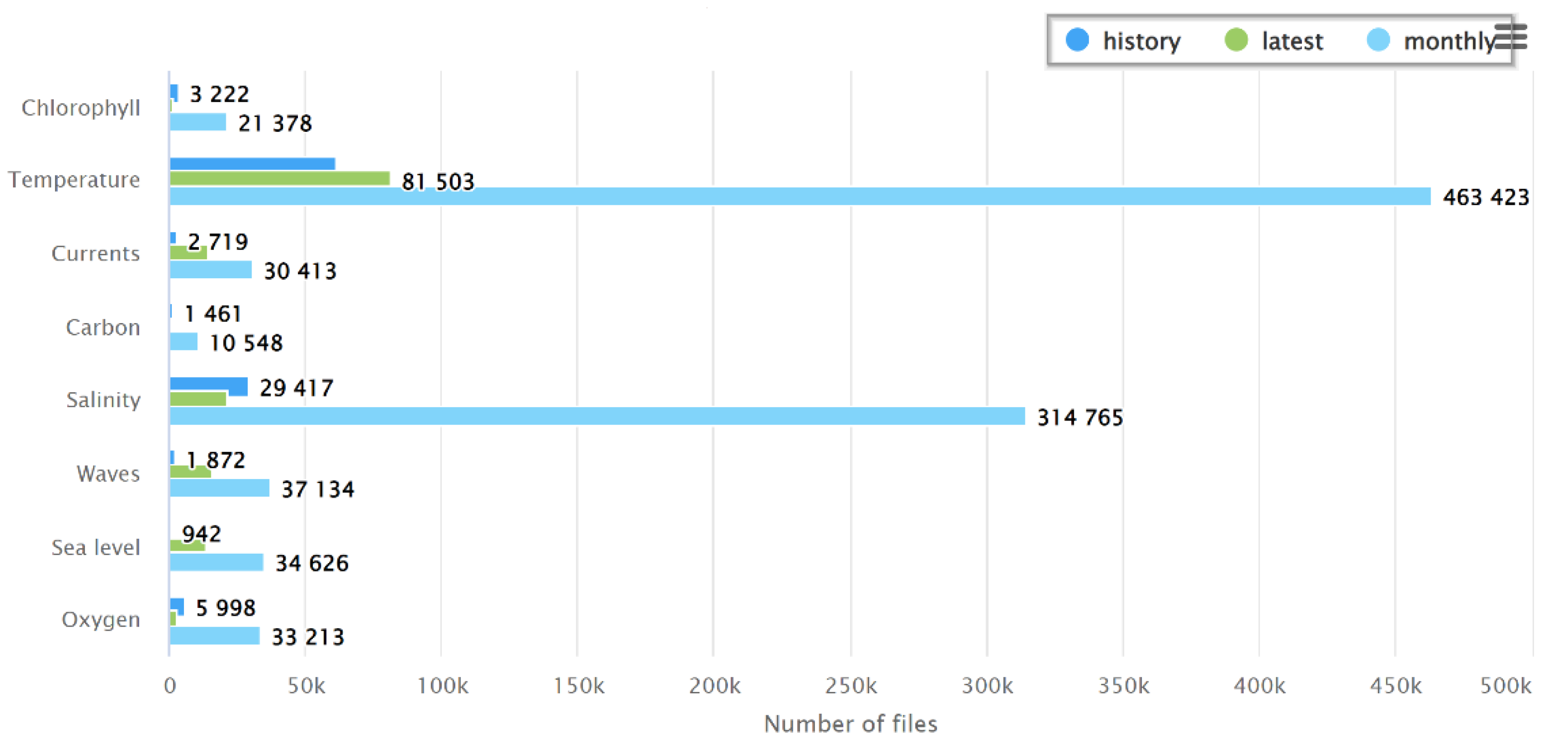
Although the technological advancements during the last decade have made possible the development of many different automatic sensors, their maturity in terms of efficiency, accuracy and overall performance varies significantly. It is characteristic that the accumulated experience from the use of CTDs as basic equipment of marine observatories for decades and the establishment of international traceable standards for these parameters result in significantly higher efficiency (Figure 3). However, even for this mature technology there are only few CTD manufacturers that offer instruments able to operate in RT mode submerged in several depths, and even fewer provide detailed documentation such as application and operation guidelines, case studies report or specialized technical manuals. Sensors measuring biological, chemical and carbonate parameters although they are radically improving over the years, they require frequent calibrations and validation procedures. To ensure the data quality, the sensors’ performance is evaluated by the scientific community with extensive field studies and intercomparison exercises such as the Fixo3 project reports for the pCO2 sensors [9,10].

2.2. Land Base Facilities

The land base facilities in HCMR Athens and Crete serve and support the POSEIDON system operations. The real time data flow, monitoring, engineering and technical services are performed in specialized laboratories and facilities. The operational center of POSEIDON is located at HCMR’s facilities in Anavyssos, Attica. It consists of a cluster of servers and storage media which provide cloud services of high availability and load distribution with the use of a series of virtual machines together with High Performance Computers capable to support the timely provision of the POSEIDON forecasting products. The servers, the storage media and the network devices are connected through multiple and high-speed links in order to achieve the highest availability and fastest response time for the hosted services. All the POSEIDON servers are running on community-driven free operating systems, while all the services and the dissemination tools are built on open-source software. The POSEIDON operational center receives, processes and analyzes all the data collected from the observing network operations. These data are archived and utilized for the production of forecasts, scientific research and outsource.
The calibration laboratory tests and calibrates sensors for a range of oceanographic parameters focusing on the unique environmental conditions of the Eastern Mediterranean Sea. The calibration facilities at the HCMR Thalassocosmos complex in Crete include fully equipped laboratories with a custom-made large calibration tank, a number of reference sensors and equipment, and all the necessary apparatuses for temperature, salinity, chlorophyll-a, turbidity, dissolved oxygen, CO2 and pH sensors calibration and validation experiments. The activities are supported by engineers and scientists, who prepare the instrumentation, perform field experiments, service and maintain the instruments and assist external users during experiments in the calibration facility. The Poseidon Calibration Lab (PCL), through transnational access activities and participation in research projects, has proven to be a powerful tool for the calibration of sensors deployed in the wider Mediterranean Sea. The instrumentation of the PCL is presented in Table 2.
The buoys laboratory (located in Anavyssos) performs maintenance work in a specially designed enclosure of 210 sq.m., which has an 8 ton crane bridge and portable lifting machines. The electronics lab is used for fault detection and repair of various electronic parts. The station dataloggers, telemetry modules and power management units are checked at a specially designed simulation benchmark; for most sensors, the manufacturer’s specified control procedures are performed. The buoy laboratory deals with the new modules and sensor integration, prepares the mooring line and anchoring lines of the fixed stations and handles the equipment storage and the consumables provision for the field operations. The glider lab is where preparation procedures such as ballasting, compass calibration and a stability test are carried out before every mission.

2.3. System Operations

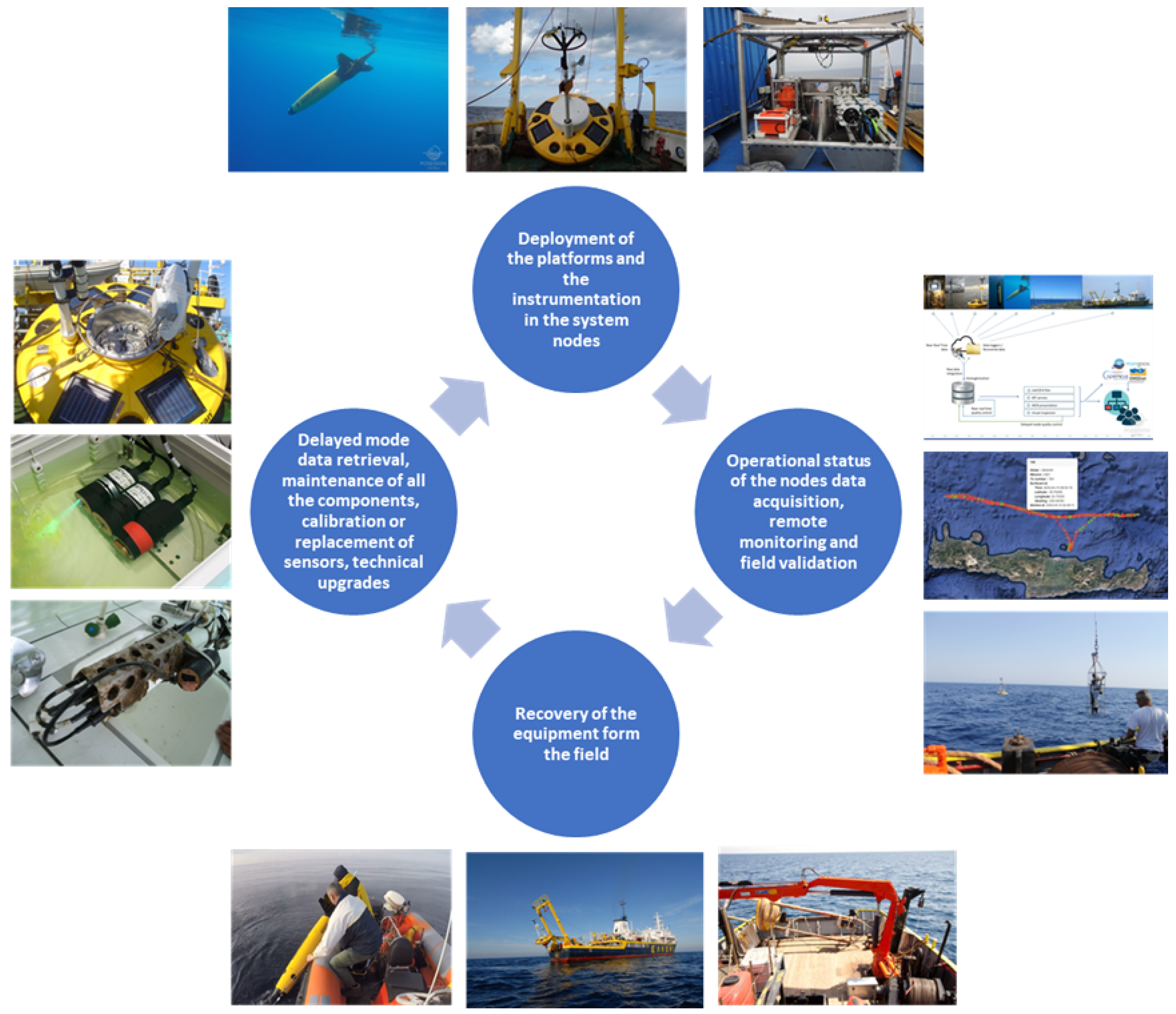
The in situ operations of the system platforms can be divided into four discrete activities:
  • Assembly and Deployment;
  • Operational status, remote monitoring and field validation;
  • Recovery;
  • Delayed mode data retrieval, maintenance, calibration, replacement of sensors, technical upgrades.
These successive activities constitute the operational cycle of the POSEIDON field platforms and define the actions that need to be performed taking into consideration the platform-specific characteristics—each platform requires different protocol during the system operations (Figure 4).

2.3.1. Deployment, Recovery and Maintenance

The maintenance of the observatory platforms, after the recovery of the equipment, is the most crucial factor in order to maintain a valid operational status. The frequency and the necessary activities performed during the maintenance procedures are dictated by the type of platform and the area/type of environment (Table 3). Moreover, the ease of access to the site/platform and the required resources needed (R/V type) determine the maintenance planning.
The buoys network is the most demanding, in terms of maintenance, compared to the other platforms of the Poseidon system. The limiting factor is the on-site maintenance during the R/V cruise and although the originally planned time window (Table 3) is adequate for the service, testing and redeployment of the equipment, all depends on the weather conditions. Furthermore, the complexity of the fixed stations modules, the extended scientific payload and the supporting equipment that needs to be maintained and tested before deployment requires a numerous scientific and technical team working closely and in coordination with the ship crew.
The maintenance procedure In the Ferrybox system is performed in the destination harbor while the ship is docked. Although it has the advantage of immediate and easy access to the ship and land facilities with a time window of 12 h before the next transect, there is a disadvantage that the system cannot be tested in realistic conditions. If needed, the operators must travel along with the ship to test the equipment or collect validation samples for analysis. The cabled observatory is designed to operate for longer periods compared to the other platforms, without maintenance. The maintenance interval (3 years) has been met once so far for the POSEIDON cabled observatory. The challenges to operate the cabled observatories are common as described by the community and documented [11,12]. The gliders servicing is performed in the laboratory between the field missions and includes fouling removal, ballasting, compass calibration and batteries refurbishment.
The maintenance of the scientific payload takes place after the recovery of the instruments, either on site during a cruise or on land facilities. Each sensor has dedicated procedures for maintenance, usually described by the manufacturer manuals or in relevant Best Practices reports available in the community. In the case of minor failures, the servicing includes replacement of parts (sealing, connectors, wipers, etc.) Especially for the sensors operating in the surface or shallow waters where the biofouling significantly affects the data quality, cleaning procedures are applied for keeping the sensing elements (conductivity cells, optical windows, etc.) free of biofouling.

2.3.2. Calibration Strategy and Methodology

Monitoring the status of sensors in terms of their operation and accuracy is important to ensure data quality. Sensors are initially calibrated and characterized by their manufacturer who usually offers in house calibration and repair services. In this case, the sensors become unavailable to the system for a considerable period of time. For parameters such as temperature and pressure, there are traceable standards, methods and reference equipment that can be used for sensor calibration experiments. Artificial or natural solutions are used for fluorescence and turbidity optical sensor calibrations, but the lack of certified standards limits the traceability of the results. For dissolved oxygen sensor calibration, the reference data are provided by Winkler analysis [13].
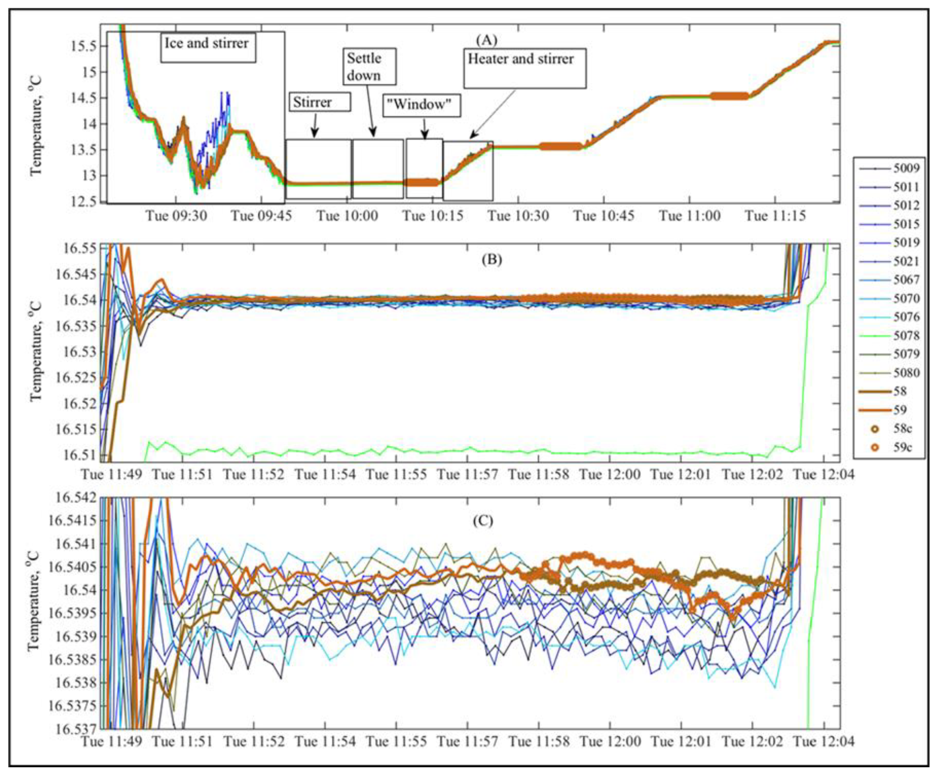
The large number of the deployed sensors and the need for high-quality data led to developing calibration methods and infrastructure to cover the needs of the POSEIDON system. The calibration procedures followed are compliant with manufacturer recommendations; however, our main focus is on data ranges recorded in the eastern Mediterranean area. Processing and evaluation of calibration data focuses on minimizing sensor drift by recalculating corrected coefficients at regular intervals. In operational mode, the buoys network hosts a total of 20 CTs, and CTDs equipped with biochemical sensors are deployed in several depths for a period of 6 to up to 12 months before they are replaced. In order to minimize the time and expenses, the calibration procedure is designed in such a way as to cover the range of the measured parameters present in Greek seas [14]. For temperature and salinity experiments, all sensors are placed in a 1000 lt thermal isolated tank filled with local seawater. The aim is to produce predefined calibration steps with an achieved homogeneity of the seawater mass inside the tank. During this multistep procedure, discrete gradients are created for each parameter using the heating elements of the tank or crushed (freshwater) ice. The physical properties of the seawater are monitored and high-frequency data and duplicate water samples are collected for later analysis with the high-precision salinometer. (Figure 5).
The uncertainty of the temperature estimation is based on the Guide to the Expression of Uncertainty in Measurement (GUM) following the recommendations by ISO (International Organisation for Standardisation) and BIPM (Bureau International des Poids et Mesures). The temperature uncertainty budget consists of three components: tank stability, tank homogeneity and reference thermometer accuracy. Tank stability and homogeneity were estimated from the readings of the reference thermometers during the custom bath characterization experiments (type A). Reference thermometer uncertainty was estimated from the specifications of the thermometers (type B). The expanded uncertainty, with a coverage factor k = 2, of the reference temperature sensors is ±0.0034 °C (Table 4).
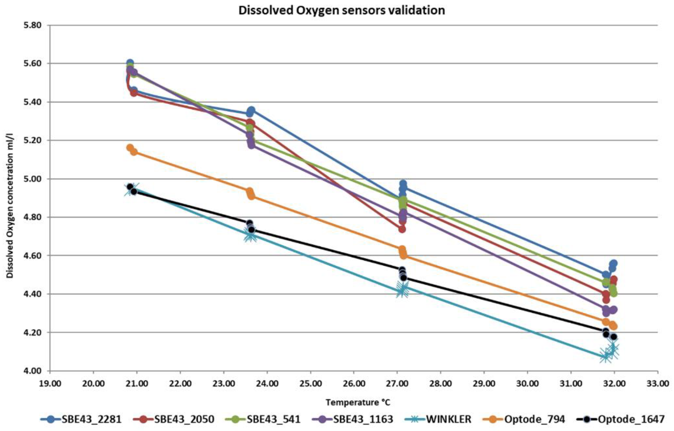
For turbidity and chl-a sensors, the calibration procedure is performed with artificial solutions of different concentrations and the experiments validate the offset and the linearity of the sensor. Dissolved oxygen sensors are validated using 0% and 100% saturated solutions and calibration data are collected for different oxygen concentrations depending on predefined salinity and temperature gradients (Figure 6). In the future, we are aiming to adjust even further the calibration range of each sensor to the specific local conditions at each deployment site and expand the calibration experiments to include pH and p C02 sensors.

2.3.3. Platforms Upgrades

The POSEIDON platform upgrades include new sensors, modules and replacements of aged equipment used to monitor the core parameters, but also the addition of new technologies to expand the group of the measured scientific parameters. In both cases, the multi-stage procedures described below allow for an evaluation of technologies and identify potential limitations or other relative issues in advance.
  • The initial activities include validation and calibration experiments in the laboratory as well as integration to platforms. Extra components such as battery packs, supporting brackets, housings and transmission systems can be manufactured to support the equipment operations;
  • In situ testing focuses on sensor/equipment deployment in coastal stations or other platforms with direct access. During the testing period, samples for cross-data validation can be collected and maintenance or service tasks are performed with smaller boats without the use of large costly R/Vs;
  • In the final stage, the new equipment is operational for an extended period on the platforms of the POSEIDON system. The data obtained from the modules are cross-checked against the measurements and data flows of the observatory.
It is demonstrated that the technology refresh and the new additions improve radically the system performance and capabilities [15]. An example is presented in Figure 7.

2.3.4. Data Flow, Field Validation and Remote Monitoring

The POSEIDON system platform data are collected by the operational center. The acquired data come in different forms depending on the type of the platform and the sampling scheme. The fixed-point stations such as buoys, cabled obs and land-based tide and HF radar stations transmit timeseries data at predefined intervals. The moving platforms, such as Argo floats, Ferrybox and Glider platforms, send the data set at the end of a mission. The real-time data sets are transmitted through satellite and mobile networks and containing full or averaged data. The raw sensor measurements are stored locally in the sensor or the platform logger for later retrieval. The retrieval of the raw data and delayed metadata is performed during the maintenance of the platform followed by a first level of process and homogenization. Then, the data set is stored in the POSEIDON database system. The IT team of the operational center developed a visualization tool for internal use that combines all the dataset sources of the POSEIDON system. This tool has proven to be very useful for supporting the delayed mode quality control of the data and evaluating the sensor performance during the field deployments.
The field validation refers to the intercomparison of different data sets obtained by the POSEIDON platforms and sampling surveys. For the validation of the POSEIDON E1-M3A and HCB stations, HCMR performs monthly surveys that include CTD casts, equipped with chl-a, turbidity and dissolved oxygen sensors, as well as water samples from various depths corresponding to the sensor installation depth. The Ferrybox measurements are validated with water samples collected by automatic water samplers or manually during the ship transect. Validation experiments for optical and chemical sensors can be performed during the port visits of the ship as well. For the Glider missions, pre- and post-deployment CTD casts serve as a comparison point for the data. Performing validation on a regular basis is a way to ensure the data quality and the proper function of the equipment. In some cases, it can minimize the operational costs, allowing for longer deployments periods (Figure 8).
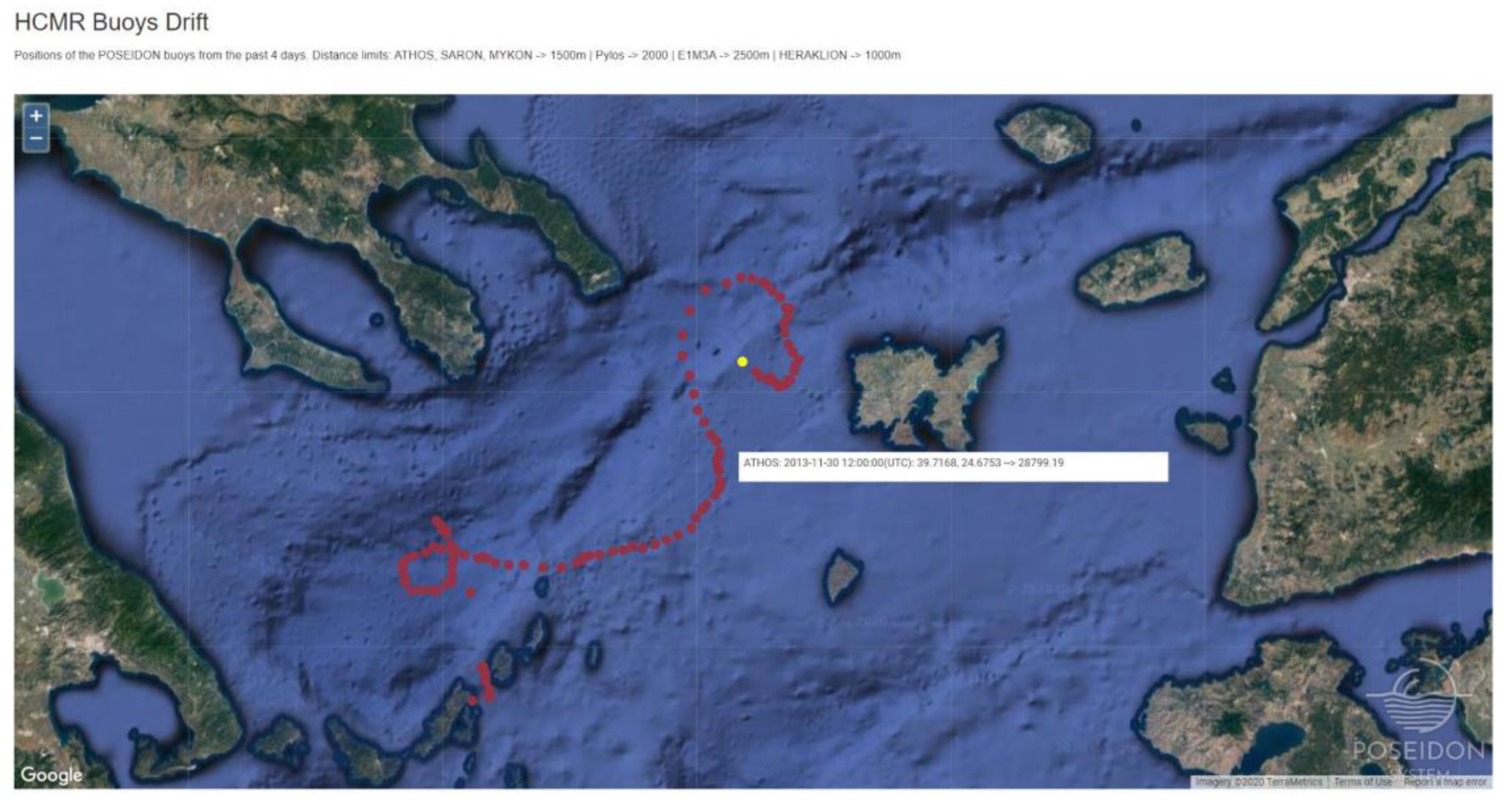
A major issue related to the POSEIDON platform status during operations is the ability to track incidents when they happen and proceed to proper response actions. Network tools were developed and are used to monitor the system’s marine platforms in real time during the deployments. For the Fixed stations and the Argo floats, a web service and a visualization tool was developed by the POSEIDON’s IT team, which provides combined information regarding the positioning and the communication status (Figure 9). The main disadvantage of the buoy’s on-board positioning system is that it is dependent on the main power unit of the station. In case of a power failure-related issue, the only information provided by the station is the loss of connection in a specific time. To overcome this limitation, the POSEIDON buoys have also been equipped since 2015 with an autonomous satellite tacker.
Using satellite communication during the gliders operation, the piloting team can remotely control and correct, if needed, the settings of the vehicle and the scientific payload. Changes to the parameters of the mission or emergency situations can be handled too. Apart from the manufacturer-provided communication software, an additional, dedicated inspection tool has been developed. The trajectory of the glider’s mission is visualized on a map along with the instant display of the most important communication metadata, while all the transmitted navigation and scientific information is available for visualization by the pilots. The plots can provide additional information, such as minimum and maximum boundaries, safety bands of operation, combinations of data series and derived parameters, which should be calculated by the direct measurements received by glider, such as the salinity and the dissolved oxygen. The FB system sends automated generated alerts and emails, in case of failure or misfunctions. The alert reports include the time and the position of the events and metadata information for the system modules.

3. Challenges during Operations

3.1. Equipment Failure

As any technological observation system, the ocean observatories suffer from equipment failure. The oceanographic equipment is exposed to one of the most energetic and corrosive environments on the planet, being the subject of environmental forcing throughout the field deployment period. The age of the equipment affects directly the endurance and the integrity of the system. The significance of the failure can range from unnoticed events to severe incidents that can lead to data loss or affect the station or platform integrity. In the last decade, the POSEIDON system has suffered from several cases of equipment failure that have caused gaps in the data flow and significant expenses for the repair or replacement of sensors and modules. The failures can be categorized as follows:
(a)
Platform failure, where the hosting platform’s (e.g., buoy) main components fail and cause the station data flow to be interrupted. These types of failures to the POSEIDON fixed stations network lead to emergency recovery of the station. Due to spare part availability and R/V operation costs, the platform failure causes a data gap. The Ferrybox system, operating in highly industrialized environment as a ship’s machine compartment, suffers from component failures caused by the high temperatures and the vibrations;
(b)
Mooring line failure can lead to an uncontrolled drifting buoy that can be a danger to navigation safety or to sensor and equipment losses at sea (Figure 9). Similar incidents have happened to the POSEIDON system and although the drifting buoys were recovered, there were losses in the underwater sensors attached to the mooring line;
(c)
Cable and connector failure are quite frequent in the oceanographic stations [16]. The inductive modem coupler and the cabling of external sensors attached to SBE CTD units used in the POSEIDON fixed stations are typical and often examples of this type of failures can cause the loss of the underwater RT telemetry or problems with the CTD logger operation;
(d)
Mechanical failure of equipment includes the disruption of material and components such as moving parts and motors, housings, attachment brackets and sealing. Given the complexity of the ocean scientific stations, these failures are quite common and can have a major impact in some cases.
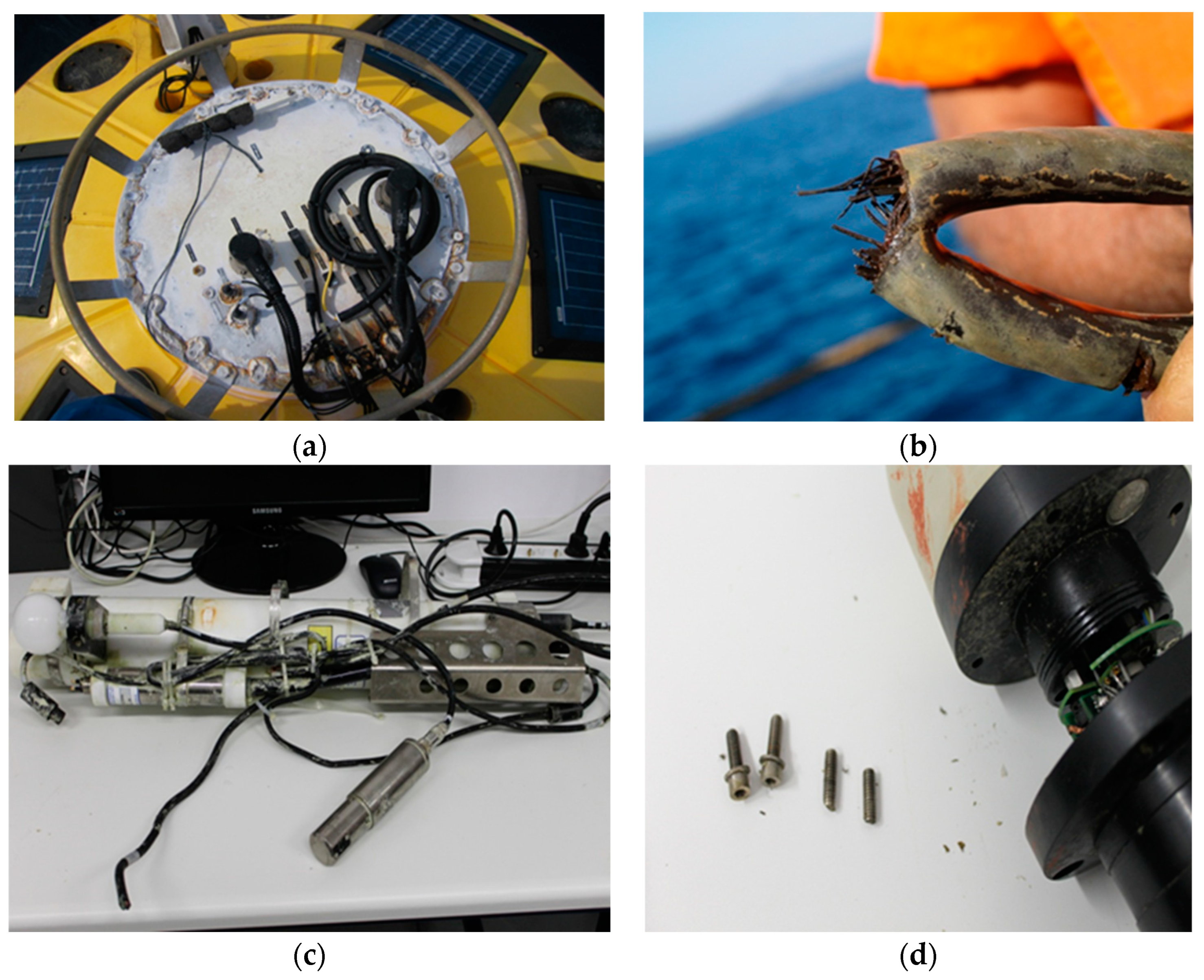
Examples of failures for the above categories are presented in details in Figure 10.

3.2. Environmental Forcing, Fouling, Corrosion

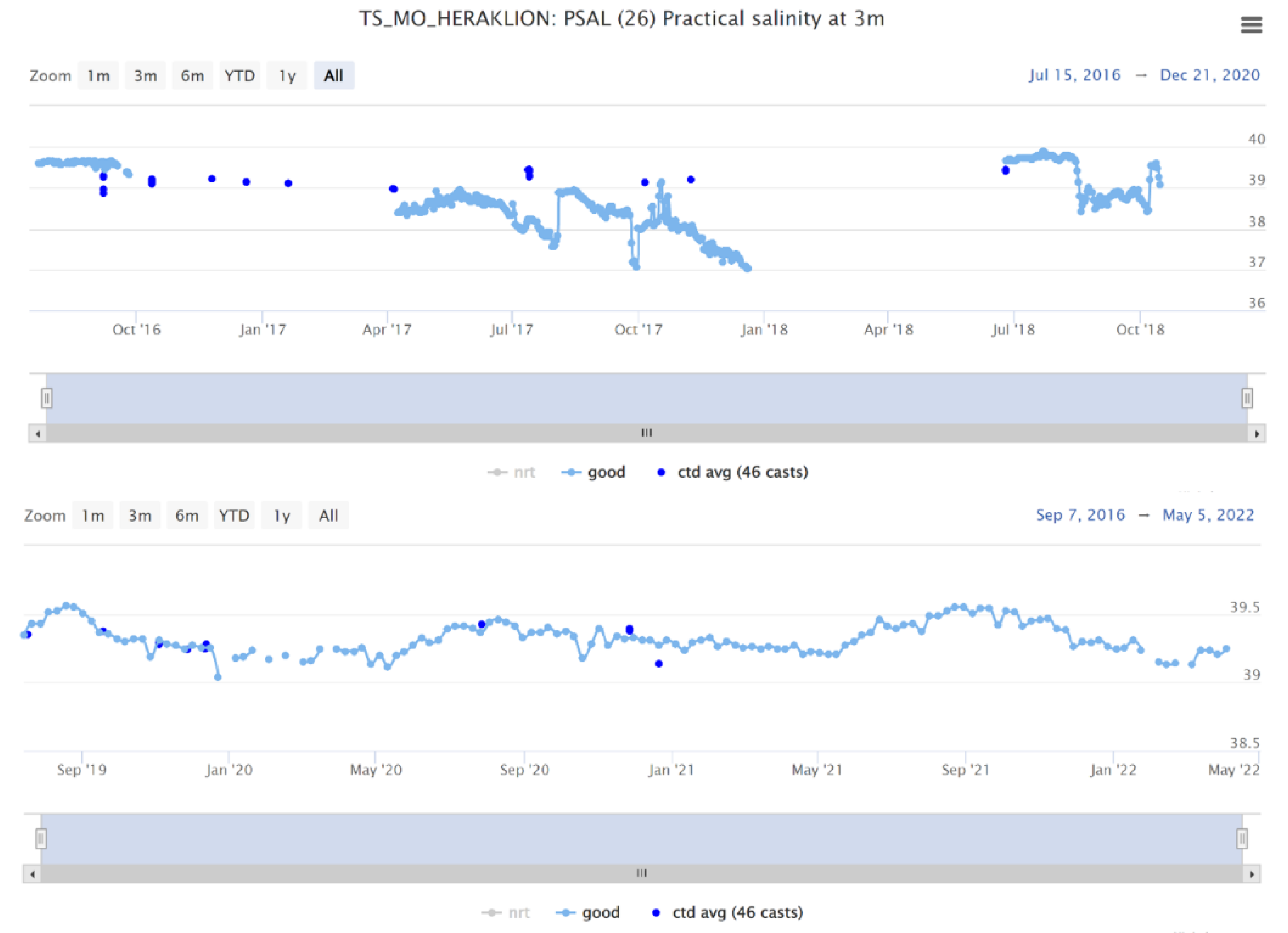
Over the last decades, oceanographic equipment and instrumentation following the state-of-the-art technological trends has improved radically and has become more efficient. Limitations in energy, transmission and data storage are no longer the most important obstacle for the long-term operation of marine observatories. Biofouling drastically affects the performance of the equipment exposed to the sea and it is one of the main limiting factors in the duration of the deployment, consequently increasing the operational cost. All the system modules are eventually affected, and the results include poor data or equipment failure. Biofouling will gradually grow on the sensors as well, and it will affect the quality of the data. If the sensor is deployed in the coastal or euphotic zone, it may face very short term biofouling effects. Techniques to prevent biofouling are implemented on instruments, especially for optical, membrane sensors and other sensors for which the interface between the seawater and the sensing element must remain intact [17]. These techniques can be active, e.g., mechanical wipers for optical sensors, or passive, such as the use of copper covers and special coatings. Although the existing antifouling methodologies have been able to extend deployment times, they are not ideal and new technologies must become effective following the rapid advancements in instrumentation [18]. Biofouling has always been present since the early beginning of the POSEIDON buoy operations (Figure 11), affecting the sensor performance and data [19].
Similar to biofouling, although does not affect directly the data quality, corrosion creates limitations to the equipment lifetime. The different metal pieces of observatory equipment in contact with seawater also show different corrosion rates. This factor must be considered throughout the design of the field system since a poor choice of materials could accelerate corrosion rates. Coatings combined with cathodic protection are the most common tools used for the protection of materials in offshore environments.

3.3. Vandalism

Vandalism of ocean data buoys or stations refers to the intentional interference with, damage to or theft of observing platforms by human action [20]. As reported, data buoy vandalism has many forms, including:
  • Fouling of mooring lines or damage to underwater cables or sensors from fishing lines or nets;
  • Using the buoy as a temporary anchor which can overstress mooring lines and damage the buoy superstructure;
  • Deliberately dragging the buoy from its moored location;
  • Cutting mooring lines or cables; and/or
  • Removing physical infrastructure, cables or sensors, or other hardware.
Vandalism of the equipment is a major issue for the long-term operation of the oceanographic buoys and other types of exposed platforms. According to the National Oceanic and Atmospheric Administration (NOAA), annually, about 10 percent of buoy data worldwide are lost due to vandalism [21]. The POSEIDON data buoy network has suffered from these forms of vandalism and, on some occasions, they have resulted in a total loss of equipment. Some recent incidents are presented in Table 5.

4. System Efficiency

Across the 20 years of operation, the percentage of valid data in the time series of the buoys network can be considered aa indicator of system efficiency. The loss or the rejection of the data is triggered for several reasons such as failures, equipment malfunctions, sensor drifts and quality control filtering. Sustainable funding is absolutely important, considering the requirements of expensive ship time, replacement parts, including spare instrumentation in case of failure or loss of equipment.
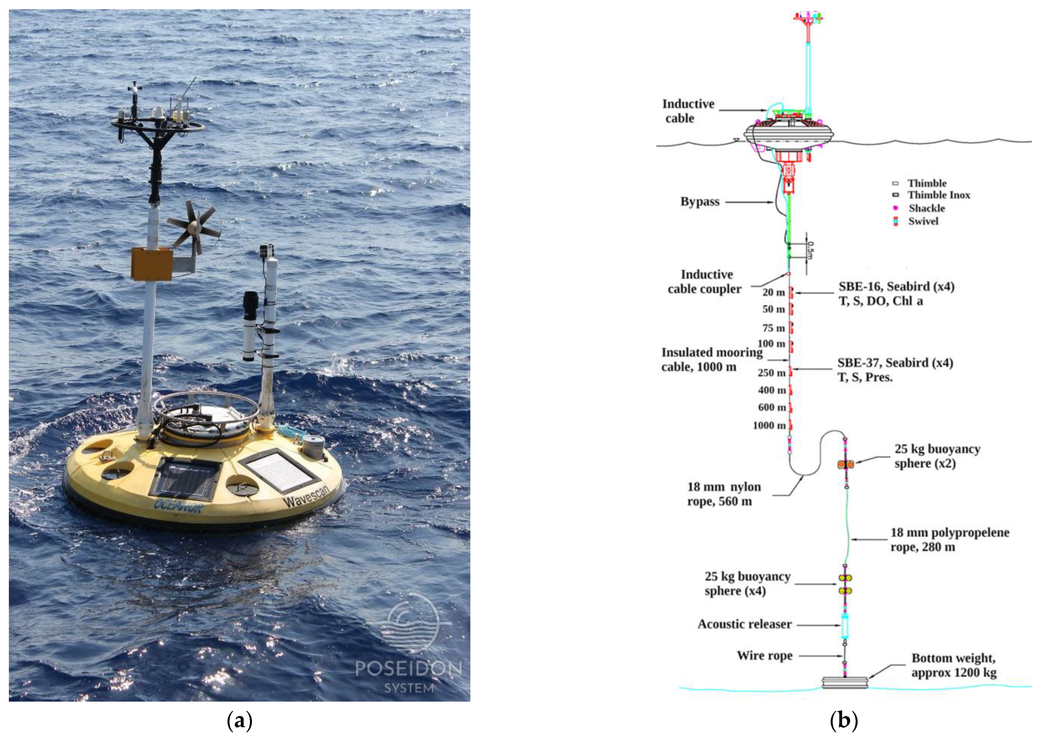
An analysis performance of the three multiparametric buoys of the POSEIDON system (Figure 12) is presented using the core parameters of temperature and salinity timeseries. The key target of the timeseries sampling is high-quality data with a minimum gap. The analysis uses the percentage of the quality-approved data, the rejected data during quality control (QC), as well as the percentage of non-operation period of the stations or sensors. The non–operation includes the time in which the buoy was retrieved from the field and stored on shore for several reasons (related to the challenges of the system operations). This gap period can be days, months or, on some occasions, years, and it is included in every depth non-operation percentage. However, the non-operation period of a sensor caused by a single failure in a specific depth is only included in that depth. The QC data set is the final product of delayed mode quality control. The QC ranges are customized for each site based on the climatology of the region and all the available data. The time range of data used is 28 May 2007 to 24 January 2022 for E1M3A, 9 November 2007 to 24 January 2022 for PYLOS, and for the ATHOS buoy—several periods between 2004 and 2022.

4.1. E1M3A

The subsurface CT sensors attached in the buoy hull with brackets in 1 m depth suffer from failures and biofouling indicated by the higher percentage of NON-OPERATION and QC-rejected data caused by the high energetic and productive surface layer (Figure 13). The sensor is powered and operated by the buoy control unit, in contrast with the sensors in the remaining depths that operate autonomously, so in case of failure of the buoy, there is no internal power unit and data logger to back up the sensor operation. The fouling that grows not only on the sensor body, but also in the submerged buoy hull and equipment, affects more drastically the salinity measurements because it alternates the dimension of the conductivity cell, the sensing element of CT sensor that is used to produce salinity data. The temperature measurements are less affected by fouling. The deeper CT sensors have less QC-approved data compared to the first 100 m because of mooring line/inductive cable failures in the deeper layers. The failures caused the loss of the RT transmission initially and eventually the total loss of instrumentation and data stored locally in the sensor loggers.

4.2. PYLOS

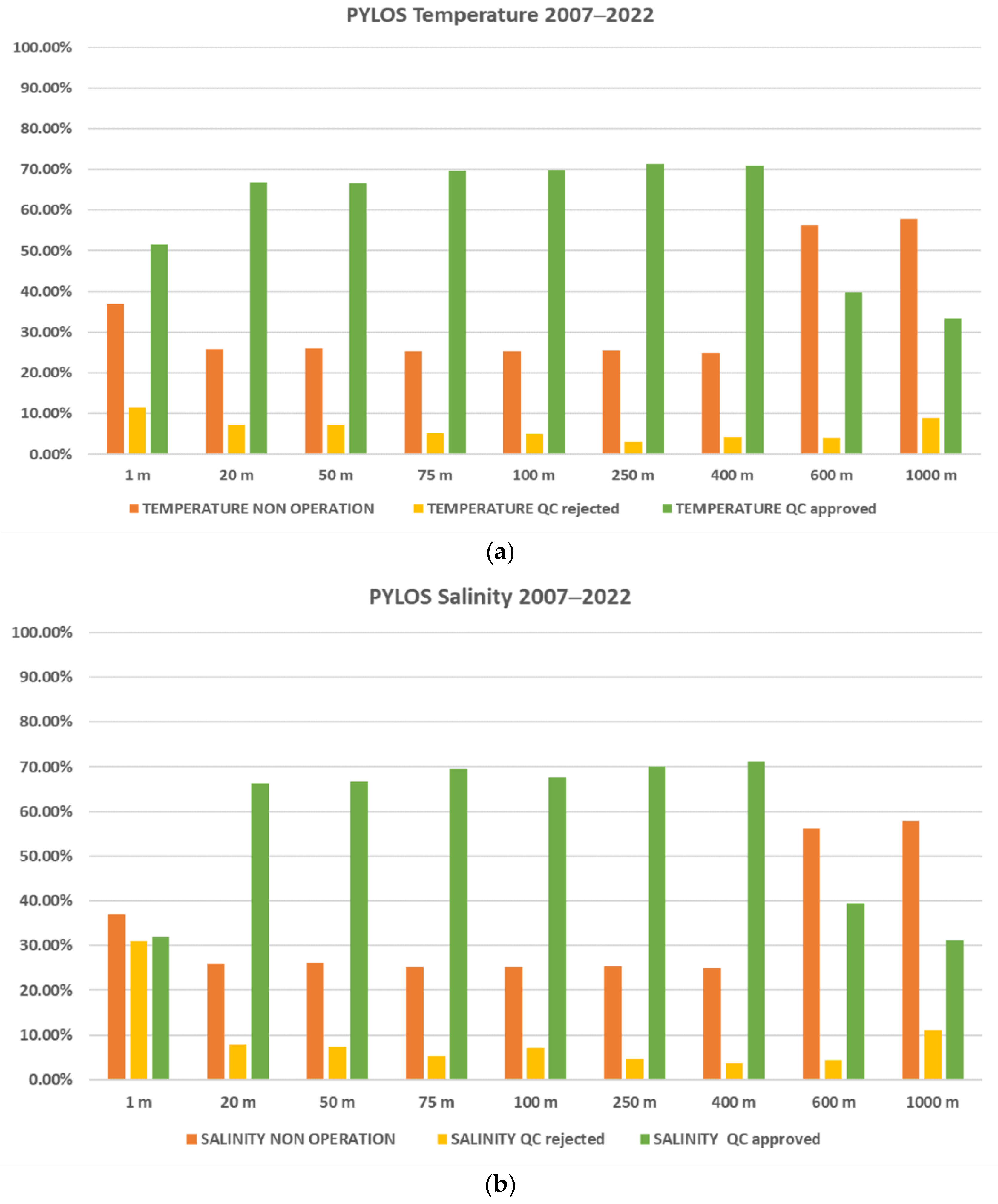
The PYLOS subsurface (1 m) temperature and salinity measurements demonstrate the same performance as the E1-M3A (Figure 14). The 600 m and 1000 m CT above 50% percentage of NON-OPERATION status were caused by the periodic absence of available sensor and sensor failures immediately after the deployment, even though it was just delivered from the manufacturer. The lower percentage of QC-rejected data compared to the E1M3A can be explained by the wider filtering criteria.

4.3. ATHOS

ATHOS buoy configuration has changed several times and it was not steady unlike the E1-M3A and PYLOS. The buoy hosts CT sensors only for the first 100 m. In the other two buoys, the CT sensors used in the upper 100 m were different versions, over the years, of SBE 16 CTD IM, an instrument that hosts additional analog and digital sensors for biochemical measurements as fluorescence/chl-a, turbidity and dissolved oxygen. The price to pay for the auxiliary sensors is the required external connecting cabling that fails often. This type of failure can compromise the whole CTD unit, creating data loss. The ATHOS buoy originally hosted only SBE 37 IM CTs, a more robust sensor with no external cabling, before upgrading eventually to a multiparameter observatory. That is why the NON-OPERATION percentage due to sensor failure is lower than for the other two buoys (Figure 15). On the other hand, the QC rejection is higher and this can be explained by the environmental conditions at the site of the buoy. The N. Aegean area is more productive than the Ionian and Cretan Seas and there are higher fouling growth rates.
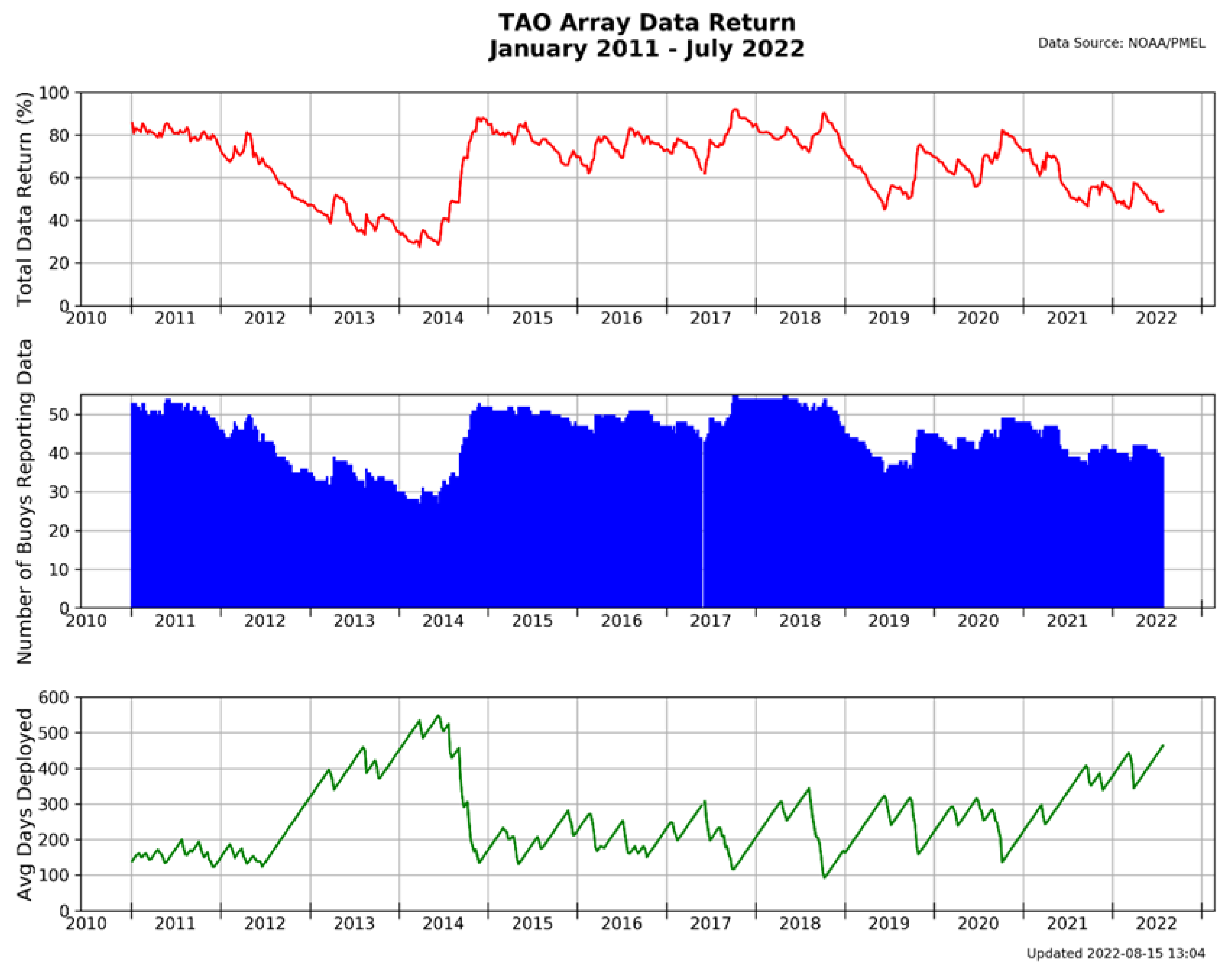
Direct comparison between observational networks performance is not straightforward. The heterogeneity both in terms of the scientific mission to be served and technological specifications of the research ocean buoy global fleet is huge compared to the Argo floats or gliders and other types of ocean platform. There is not a commonly accepted methodology for the evaluation of the performance of the ocean buoys. Data return, as the percentage of the data retrieved or data supposed to be retrieved according to the buoy sampling scheme, is used widely as an indicator of performance. For the POSEIDON multiparametric buoys, the averaged data return of quality-approved data for surface (1 m) temperature and salinity measurements is 59.42% and 37.24%. The averaged data return for the underwater instrumentation is 64.28% for temperature and 62.64% for salinity. These numbers refer to useful data for science after different levels of quality control. The average of QC-rejected data is 12.73% for underwater temperature data and 12.28% for salinity. In general, peak performance is 70%. Figure 16, available on the Pacific Marine Environmental Laboratory (PMEL) website, presents the historical Tropical Atmosphere Ocean (TAO/TRITON) moorings network data return percentage, the number of buoys reporting data and the averaged days of field deployment from January 2011 to July 2022, highlighting the importance of the maintenance frequency for the performance of the network [22].
The overall Prediction and Research Moored Array in the Tropical Atlantic (PIRATA) data return percentages from the deployment of the first buoy in September 1997 to the end of December 2006 for subsurface temperature measurements were 72% in real-time and 82% in delayed mode [23]. The buoys’ delayed mode data return over the 1997–2017 period average mean value for all sensors at each moored location ranged between 72 and 93% [24]. In a comparison of ATLAS and T-FLEX buoy type data, the return rate of salinity RT data was 72% and 85% [25]. The Japan Agency for Marine-Earth Science and Technology (JAMSTEC) reported the delayed mode return rate of CTD sensors operating at 1, 10, 20, 40 and 100 m water depth in the range 80–90% for temperature and 75–87% for salinity [26]. The data were averaged over all the selected mooring periods. In the North Indian Ocean buoys, the sea water conductivity sensors recorded an average annual data availability of 72%, with 47% of the failures being environmentally induced [27].

5. Contributions to the Ocean Observatories Development and Open Access to the System

In addition to the system development and the continuous operations of the POSEIDON system, the scientific and engineering team participated actively and shared the technological common knowledge with the international community in an ongoing procedure to identify and adopt best practices for the design [28], the operation of ocean monitoring systems and the sensor calibration [29,30]. This effort is focused on introducing a new open-access, permanent digital repository of best practices documentation (oceanbestpractices.org) that is part of the Ocean Best Practices System (OBPS) contributing to improving the future ocean observing [31].
Through transnational calls and research projects access, provision of engineering services, data products, technology testing facilities and demonstrating services have been offered repeatedly to scientists and industry partners originating from several scientific fields. Since 2010, the POSEIDON system has hosted 15 user proposed projects, 13 internationally and 2 nationally funded, offering access to the nodes and the laboratories of the infrastructure [32].
The joint effort of the scientific user group and the POSEIDON team in experiments for scientific instrumentation calibration have resulted in advancing the scientific methodology for the precise characterization of the instrumentation deployed in the East Med’s unique environmental conditions and in improving the impact of regional RIs with the adoption of a common conceptual structure [33,34]. New sensing technologies for ocean acidification were introduced in the operational data acquisition scheme to study the seasonal pH variability. In the Saronikos station, a new spectrophotometric pH-based system was deployed over the period between September 2013 and October 2014. The tested instrumentation proved capable of providing sea-surface temperature and salinity, together with highly accurate pH values [35]. Innovative cost-effective technologies were also demonstrated in operational mode, adding high-precision pH observations to the suite of measurements that are already part of the Ferrybox infrastructure, thus better characterizing the carbonate system [36]. Other scientific access activities in the POSEIDON field network include the testing of cost-effective instrumentation and samplers for microplastics monitoring, vertical distributions and settlement of deep-sea larvae and monitoring of organic contaminants by passive samplers.
Through the HIMIOFoTS access call, the proposal “Underwater passive acoustic monitoring of cetaceans using the POSEIDON underwater gliders—ΥΠAΚOUE” was granted. The project was a cooperation between the Sea Mammal Research Unit, Scottish Ocean Institute, University of St Andrews, and the Operational Oceanography department of HCMR for the monitoring of cetaceans and environmental noise in the Cretan Sea [5]. During the CLAIM project, a passive filter system able to operate in the FB systems and other types of vessels equipped with a flow-through sea water pumping system was developed. The system was deployed in several types of vessels to provide information about marine microlitter distribution and control data points for validation of advanced micro- and macroplastic models. In the framework of the national MARRE project, the detection system KATERINA II was attached to the POSEIDON Athos station in order to provide continuous measurement and monitoring of natural and artificial radioactivity. The calibration and preparation of the KATERINA II system was achieved with the support of the MERL group, while the installation of the detection system was completed with the support of the POSEIDON engineers and HCMR’s diving team [37].
Apart from the scientific and research community, access to POSEIDON was also provided to industry applicants. Design and engineering services were offered for the development of an underwater strain gauges data acquisition module to study the ageing of composites materials, a very critical factor for composite underwater structures that operate for prolonged periods of time. Several batches of composite filament wound ring, arc and straight and two filaments wound Carbon Fiber Reinforced Plastics CFRP housings were deployed in a depth of about 900 m at the E1M3A obs. Approximately every 10 months, the mooring line was recovered, the logger data were retrieved and a batch of specimens was collected in order to be tested in the laboratory [38]. The LETS_SAT TNA project aimed to test the OpenIchnos tracking technology in fixed-point oceanographic platforms under the influence of a wide range of environmental conditions (winds, waves, temperature, sea sprays, etc.) The simultaneous access on three platforms for extended periods of time (1 year) was offered in order to fully exploit and test the operational capabilities of the product. To meet the increased demand for power by modern and sophisticated sensors and modules, FURGO Oceanor replaced one half of the PYLOS buoy with a new hull containing fuel cells and a new water-based cooling system. The new power system was tested for a period of more than 2 years in realistic conditions.

6. Summary and Perspectives

The POSEIDON Marine Forecasting and Information System for the Greek Seas is a state-of-the-art, widely recognizable operational system. The system consists of the following components: The observing system, which is comprises a network of different observing platforms; The forecasting system, which consists of a suite of numerical models that provide daily basis atmospheric, wave, hydrodynamic and ecosystem forecasts for the next five days; The marine technology unit that provides the engineering and technical backbone to operate the observing facilities, while it is also responsible for the testing and integration of new technologies in the monitoring platforms; The data management and dissemination unit, which collects and processes the data from the monitoring network and distributes the observing and forecasting products to the linked European Infrastructures and to the public. The scientific objectives of POSEIDON are to provide knowledge and support in the study of the ocean mechanisms and their variability, as well as to address the sensitivity of marine ecosystem and biodiversity to combined natural forcing factors and anthropogenic pressures. In addition to the scientific contribution and driven by societal needs, the system provides products such as quality and validated forecasts of the marine environment, proxy estimations, hazard mapping, and warning systems. As a part of the national scale RI: HIMIOFoTS, the POSEIDON system is actively contributing to integrating the Greek observing capacity in the ocean–coastal–inland nexus under a unified structure with a common strategy and priority setting based on the national requirements and the European and international landscape.
The long-term goals in the POSEIDON technology development are driven by setting ambitious targets such as strengthening the high-resolution surface and mid-layer data and products, operating in deeper regions and introducing new variables. These targets will be achieved by (a) coupling technology and science beyond the state of the art in order to actively participate in the technological development and innovating solutions, (b) investing in personnel and facilities for operating, testing and validating sensors and equipment (pressure chambers and experimental tanks, testing equipment and reference standards) and (c) networking on the international and national levels in order to make the POSEIDON not only the most advanced monitoring, forecasting and information system in the East Med, but also a leader in marine technology development. New monitoring technologies for pollutants and eDNA, advanced data analysis techniques, high accuracy instrumentation for eutrophication and acidification studies, coupled monitoring schemes with aerial, surface and underwater drones, animal-borne scientific payloads, cost effective citizen operated sensors and platforms, UIoT and cloud architectures in combination with AI data analysis and advanced modelling tools are under development and will be eventually integrated in the marine research observatories, leading to a new era of ocean exploration and scientific discoveries.

Author Contributions

Conceptualization, M.N., L.P. and G.P.; investigation, L.P., G.P., G.K., C.F. and D.B.; resources, D.B., C.F., P.P., E.B., M.S. and M.N.; data curation C.F., D.B., P.P., M.S., M.P., E.B., S.C., D.K., N.Z., S.M., D.D., A.M.(Antigoni Moira), A.M. (Aspasia Marvoudi), G.A., A.P., C.O., N.S. and M.N.; writing—original draft preparation, M.N., G.P. and L.P.; writing—review and editing, M.N.; visualization, M.N., L.P. and G.A.; supervision, L.P., G.P. and G.K.; project administration, L.P.; funding acquisition, L.P., G.P. and G.K. All authors have read and agreed to the published version of the manuscript.

Funding

This work was supported by the project HIMIOFoTS (MIS 5002739), which was implemented under the Action “Reinforcement of the Research and Innovation Infrastructure”, funded by the Operational Programme “Competitiveness, Entrepreneurship and Innovation” (NSRF 2014–2020) and co-financed by Greece and the EU.

Institutional Review Board Statement

Not applicable.

Informed Consent Statement

Informed consent was obtained from all subjects involved in the study.

Data Availability Statement

The data presented in this study are available in https://poseidon.hcmr.gr/ (accessed on 5 October 2022).

Conflicts of Interest

The authors declare no conflict of interest.

References

  1. Nittis, K.; Zervakis, V.; Perivoliotis, L.; Papadopoulos, A.; Chronis, G. Operational Monitoring and Forecasting in the Aegean Sea: System Limitations and Forecasting Skill Evaluation. Mar. Pollut. Bull. 2001, 43, 154–163. [Google Scholar] [CrossRef] [PubMed]
  2. Perivoliotis, L.; Petihakis, G.; Korres, G.; Ballas, D.; Frangoulis, C.; Paris, P.; Ntoumas, M.; Pettas, M.; Chalkiopoulos, A.; Sotiropoulou, M.; et al. The POSEIDON system, an integrated observing infrastructure at the Eastern Mediterranean as a contribution to the European Ocean Observing System. In Proceedings of the 8th EuroGOOS Conference, Bergen, Norway, 3–5 October 2017; Available online: http://eurogoos.eu/download/publications/EuroGOOS-2017-Conference-Proceedings.pdf (accessed on 29 September 2022).
  3. Petihakis, G.; Perivoliotis, L.; Korres, G.; Ballas, D.; Frangoulis, C.; Pagonis, P.; Ntoumas, M.; Pettas, M.; Chalkiopoulos, A.; Sotiropoulou, M.; et al. An integrated open-coastal biogeo-chemistry, ecosystem and biodiversity observatory of the eastern Mediterranean–the Cretan Sea component of the POSEIDON system. Ocean. Sci. 2018, 14, 1223–1245. [Google Scholar] [CrossRef] [Green Version]
  4. Lykousis, V.; Nittis, K.; Ballas, D.; Perivoliotis, L.; Kassis, D.; Pagonis, P.; Sakellariou, D. The Hellenic deep sea observatory: Science objectives and implementation. In SEAFLOOR OBSERVATORIES; Springer: Berlin/Heidelberg, Germany, 2015; pp. 81–103. [Google Scholar] [CrossRef]
  5. Bourma, E.; Perivoliotis, L.; Petihakis, G.; Korres, G.; Frangoulis, C.; Ballas, D.; Zervakis, V.; Tragou, E.; Katsafados, P.; Spyrou, C.; et al. The Hellenic Marine Observing, Forecasting and Technology System—An Integrated Infrastructure for Marine Research. J. Mar. Sci. Eng. 2022, 10, 329. [Google Scholar] [CrossRef]
  6. Kassis, D.; Krasakopoulou, E.; Korres, G.; Petihakis, G.; Triantafyllou, G.S. Hydrodynamic features of the South Aegean Sea as derived from Argo T/S and dissolved oxygen profiles in the area. Ocean Dyn. 2016, 66, 1449–1466. [Google Scholar] [CrossRef]
  7. Korres, G.; Ntoumas, M.; Potiris, M.; Petihakis, G. Assimilating Ferry Box data into the Aegean Sea model. J. Mar. Syst. 2014, 140, 59–72. [Google Scholar] [CrossRef]
  8. Potiris, E.; Frangoulis, C.; Kalampokis, A.; Ntoumas, M.; Pettas, M.; Petihakis, G.; Zervakis, V. 2018: ADCP observations of migration patterns of zooplankton in the Cretan Sea. Ocean Sci. 2018, 14, 783–800. [Google Scholar] [CrossRef] [Green Version]
  9. Alliance for Coastal Technologies. Available online: www.act-us.info/evaluations.php (accessed on 5 October 2022).
  10. International Ocean Carbon Coordination Project (IOCCP). Available online: www.ioccp.org/index.php/instruments-and-sensors?id=463 (accessed on 5 October 2022).
  11. Del-Rio, J.; Nogueras, M.; Toma, D.M.; Martinez, E.; Artero-Delgado, C.; Bghiel, I.; Martinez, M.; Cadena, J.; Garcia-Benadi, A.; Sarria, D.; et al. Obsea: A Decadal Balance for a Cabled Observatory Deployment. IEEE Access 2020, 8, 33163–33177. [Google Scholar] [CrossRef]
  12. Fischer, P.; Brix, H.; Baschek, B.; Kraberg, A.; Brand, M.; Cisewski, B.; Riethmüller, R.; Breitbach, G.; Möller, K.O.; Gattuso, J.-P.; et al. Operating Cabled Underwater Observatories in Rough Shelf-Sea Environments: A Technological Challenge. Front. Mar. Sci. 2020, 7, 551. [Google Scholar] [CrossRef]
  13. George, P.; Michael, H.; Wilhelm, P.; Rajesh, N.; Jukka, S.; Florence, S.; JERICO. Report on Calibration Best Practices. D4.2.; Ifremer for JERICO Project: Issy-les-Moulineaux, France. 2014. Available online: https://www.jerico-ri.eu/download/filebase/jerico_fp7/deliverables/D4_2_Report%20on%20Calibration%20best%20practices_v1-3rev.pdf (accessed on 1 October 2022).
  14. Ntoumas, E.; Kassis, D.; Potiris, M.; Ballas, D.; Chondronassios, T.; Pagonis, P.; Tsagaraki, T.; Podaras, D.; Manousakis, L.; Zervakis, V.; et al. Activities of the calibration laboratory at HCMR-Crete—Progress and challenges. In Proceedings of the Sixth EuroGOOS Conference, Sopot, Poland, 4–6 October 2011. [Google Scholar]
  15. Smith, L.M.; Yarincik, K.; Vaccari, L.; Kaplan, M.B.; Barth, J.A.; Cram, G.S.; Fram, J.P.; Harrington, M.; Kawka, O.E.; Kelley, D.S.; et al. Lessons Learned From the United States Ocean Observatories Initiative. Front. Mar. Sci. 2019, 5, 494. [Google Scholar] [CrossRef]
  16. Howe, B.; McRae, E. Deep Trouble! Common Problems for Ocean Observatories. Eos 2017, 98. [Google Scholar] [CrossRef]
  17. Delauney, L.; Compère, C.; Lehaitre, M. Biofouling protection for marine environmental sensors. Ocean Sci. 2010, 6, 503–511. [Google Scholar] [CrossRef] [Green Version]
  18. Delgado, A.; Briciu-Burghina, C.; Regan, F. Antifouling Strategies for Sensors Used in Water Monitoring: Review and Future Perspectives. Sensors 2021, 21, 389. [Google Scholar] [CrossRef] [PubMed]
  19. Zervakis, V.; Krasakopoulou, E.; Assimakopoulou, G.; Renieris, P.; Ballas, D.; Mallios, A.; Papageorgiou, E. In situ calibration of biofouling-prone oceanographic sensors in the framework of the POSEIDON project. In Elsevier Oceanography Series; Elsevier: Amsterdam, The Netherlands, 2003; Volume 69, pp. 373–375. [Google Scholar] [CrossRef]
  20. Data Buoy Cooperation Panel (DBCP). Outreach Strategy to Reduce Damage to Ocean Data Buoys from Vandalism. Available online: https://www.ocean-ops.org/dbcp/doc/2017-MISC-OBS-Data-Buoys-Vandalism-Strategy-171246_en.pdf (accessed on 5 October 2022).
  21. NOAA Office of General Counsel. Available online: https://www.gc.noaa.gov/gcil_buoys.html (accessed on 5 October 2022).
  22. Pacific Marine Environmental Laboratory. Available online: https://www.pmel.noaa.gov/gtmba/historic-tao-data-return (accessed on 5 October 2022).
  23. Bourlès, B.; Lumpkin, R.; McPhaden, M.J.; Hernandez, F.; Nobre, P.; Campos, E.; Yu, L.; Planton, S.; Busalacchi, A.; Moura, A.D.; et al. The PIRATA program: History, accomplishments, and future directions. Bull. Am. Meteorol. Soc. 2008, 89, 1111–1126. [Google Scholar] [CrossRef]
  24. Bourlès, B.; Araujo, M.; McPhaden, M.J.; Brandt, P.; Foltz, G.R.; Lumpkin, R.; Giordani, H.; Hernandez, F.; Lefèvre, N.; Nobre, P.; et al. PIRATA: A Sustained Observing System for Tropical Atlantic Climate Research and Forecasting. Earth Space Sci. 2019, 6, 577–616. [Google Scholar] [CrossRef]
  25. Freitag, H.P.; Mcphaden, M.J.; Connell, K.J. Comparison of ATLAS and T-Flex Mooring Data. Tech. Rep. 2018. [Google Scholar] [CrossRef]
  26. Fujii, N.; Ueki, I.; Furuhata, M.; Hashimukai, T.; Yamada, M.; Tatamisashi, S.; Fukuda, K.; Nagahama, T.; Yokota, M.; Fukuda, T.; et al. Data return rate and its improvement for m-TRITON buoy. JAMSTEC Rep. Res. Dev. 2017, 24, 10–20. [Google Scholar] [CrossRef] [Green Version]
  27. Venkatesan, R.; Senthilkumar, P.; Vedachalam, N.; Murugesh, P. Biofouling and its effects in sensor mounted moored observatory system in Northern Indian Ocean. Int. Biodeterior. Biodegradation 2017, 116, 198–204. [Google Scholar] [CrossRef]
  28. Coppola, L.; Ntoumas, M.; Bozzano, R.; Bensi, M.; Hartman, S.E.; Charcos Llorens, M.; Craig, J.; Rolin, J.F.; Giovanetti, G.; Cano, D.; et al. Handbook of Best Practices for Open Ocean Fixed Observatories. Available online: https://repository.oceanbestpractices.org/handle/11329/302 (accessed on 1 October 2022).
  29. George, P.; Kai, S.; Carlos, H.; Pierre, T.; Manolis, N.; Wilhelm, P.; Julien, M.; Laurent, M.; JERICO. Report on best practices in conducting operations and maintaining. D 4.4; Ifremer for JERICO Project: Issy-les-Moulineaux, France. 2012. Available online: https://bestpractice.emsd.gov.hk/assets/booklet/FS/Fire_Service_installations_O&M_Best_Practices_Booklet(English_version).pdf (accessed on 1 October 2022).
  30. Nair, R.; Petihakis, G.; Ntoumas, M. Uncertainty Estimation for Temperature, Salinity & Chlorophyll-a. D# 5.5. Version 1; Ifremer for JERICO Project: Issy-les-Moulineaux, France, 2015. [Google Scholar] [CrossRef]
  31. Pearlman, J.; Bushnell, M.; Coppola, L.; Karstensen, J.; Buttigieg, P.L.; Pearlman, F.; Simpson, P.; Barbier, M.; Muller-Karger, F.E.; Munoz-Mas, C.; et al. Evolving and Sustaining Ocean Best Practices and Standards for the Next Decade. Front. Mar. Sci. 2019, 6, 277. [Google Scholar] [CrossRef]
  32. Frangoulis, C.; Petihakis, G.; Perivoliotis, L.; Korres, G.; Ballas, D.; Pagonis, P.; Notumas, M.; Pettas, M.; Sotiropoulou, M.; Bekiari, M.; et al. The POSEIDON Supersite Observatory. A Technological Test-bed for the Eastern Mediterranean. In OCEANS 2019-Marseille; IEEE: Piscataway, NJ, USA, 2019; pp. 1–6. [Google Scholar] [CrossRef]
  33. Pensieri, S.; Bozzano, R.; Schiano, M.E.; Ntoumas, M.; Potiris, E.; Frangoulis, C.; Podaras, D.; Petihakis, G. Methods and Best Practice to Intercompare Dissolved Oxygen Sensors and Fluorometers/Turbidimeters for Oceanographic Applications. Sensors 2016, 16, 702. [Google Scholar] [CrossRef] [Green Version]
  34. Bozzano, R.; Pensieri, S.; Pensieri, L.; Cardin, V.; Brunetti, F.; Bensi, M.; Petihakis, G.; Tsagaraki, T.M.; Ntoumas, M.; Podaras, D.; et al. The M3A network of open ocean observatories in the Mediterranean Sea. In 2013 MTS/IEEE OCEANS-Bergen; IEEE: Piscataway, NJ, USA, 2013; pp. 1–10. [Google Scholar] [CrossRef]
  35. González-Dávila, M.; Santana-Casiano, J.M.; Petihakis, G.; Ntoumas, M.; de Tangil, M.S.; Krasakopoulou, E. Seasonal pH variability in the Saronikos Gulf: A year-study using a new photometric pH sensor. J. Mar. Syst. 2016, 162, 37–46. [Google Scholar] [CrossRef]
  36. Andrew, K.; Manolis, N. JERICO-NEXT TNA: CarbonAS pH dataset March-June 2018; SEANOE: Issy-les-Moulineaux Cede, France, 2018. [Google Scholar] [CrossRef]
  37. Tsabaris, C.; Androulakaki, E.; Ballas, D.; Alexakis, S.; Perivoliotis, L.; Iona, A. Radioactivity Monitoring at North Aegean Sea Integrating In-Situ Sensor in an Ocean Observing Platform. J. Mar. Sci. Eng. 2021, 9, 77. [Google Scholar] [CrossRef]
  38. Papadakis, A.; Konstantinidis, G.K.; Tsouvalis, N.G. Long Term Deep Sea Exposure Effect on the Mechanical Properties of Filament Wound Composites. In Proceedings of the ECCM18-18th European Conference on Composite Materials, Athens, Greece, 24–28 June 2018. [Google Scholar]
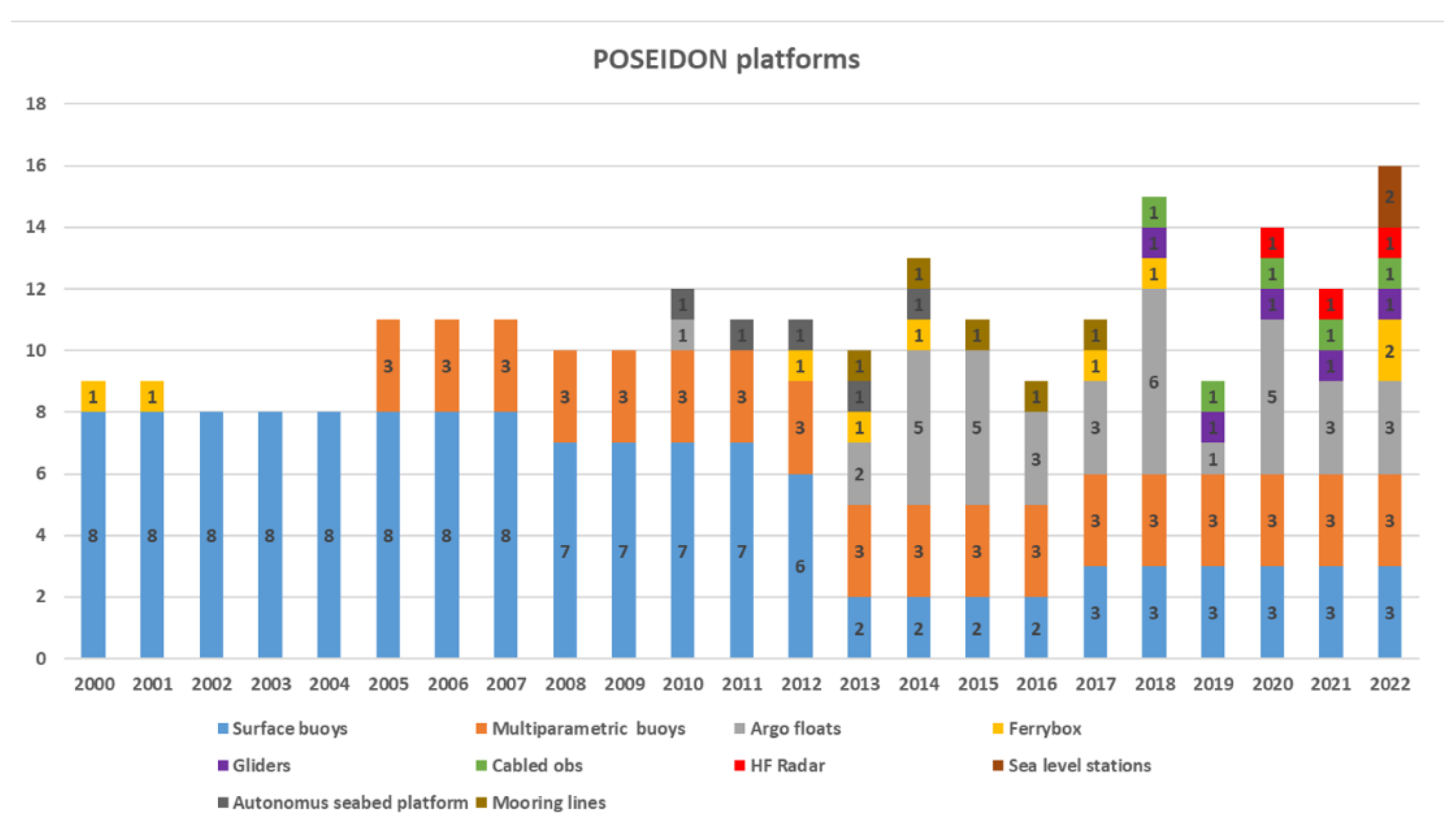
Figure 1. The evolution of the POSEIDON system with the addition of new platforms and technologies for 2000–2022.
Jmse 10 01932 g001
Figure 2. The POSEIDON system operational nodes and shore facilities.
Jmse 10 01932 g002
Figure 3. The global ocean in situ NRT data files per parameter as presented to the Copernicus Marine Service (CMEMS) In Situ TAC monitoring webpage (www.marineinsitu.eu/monitoring/, accessed on 5 October 2022). The temperature and salinity data files are significant more than the other parameters.
Jmse 10 01932 g003
Figure 4. The operational scheme of the POSEIDON system.
Jmse 10 01932 g004
Figure 5. Panel (A) summarizes the temperature calibration procedure for 12 SBE 37 IM CT sensors. Panel (B) shows all sensors’ data that were collected during a calibration step. Panel (C) is the same as panel (B), only zoomed in for clarity. Bold lines denote the reference sensors and cycles denote the readings that belong to a calibration “window”.
Jmse 10 01932 g005
Figure 6. The dissolved oxygen sensor validation procedure. Data from 6 sensors are compared with the results of the Winkler analysis during an experiment where the seawater temperature was technically raised in order to reduce the dissolved oxygen concentration.
Jmse 10 01932 g006
Figure 7. This figure demonstrates the radical improvement of the dissolved oxygen data in the POSEIDON buoys by the introduction of a new optical sensor in 2017. Panel (a) presents the dissolved oxygen timeseries form the E1M3A where the new sensors data corresponds to the period after 2017. Panel (b) focuses on the 50 m time series to demonstrate the better correlation of the optical sensor data with filed validation data (blue and red dots).
Jmse 10 01932 g007
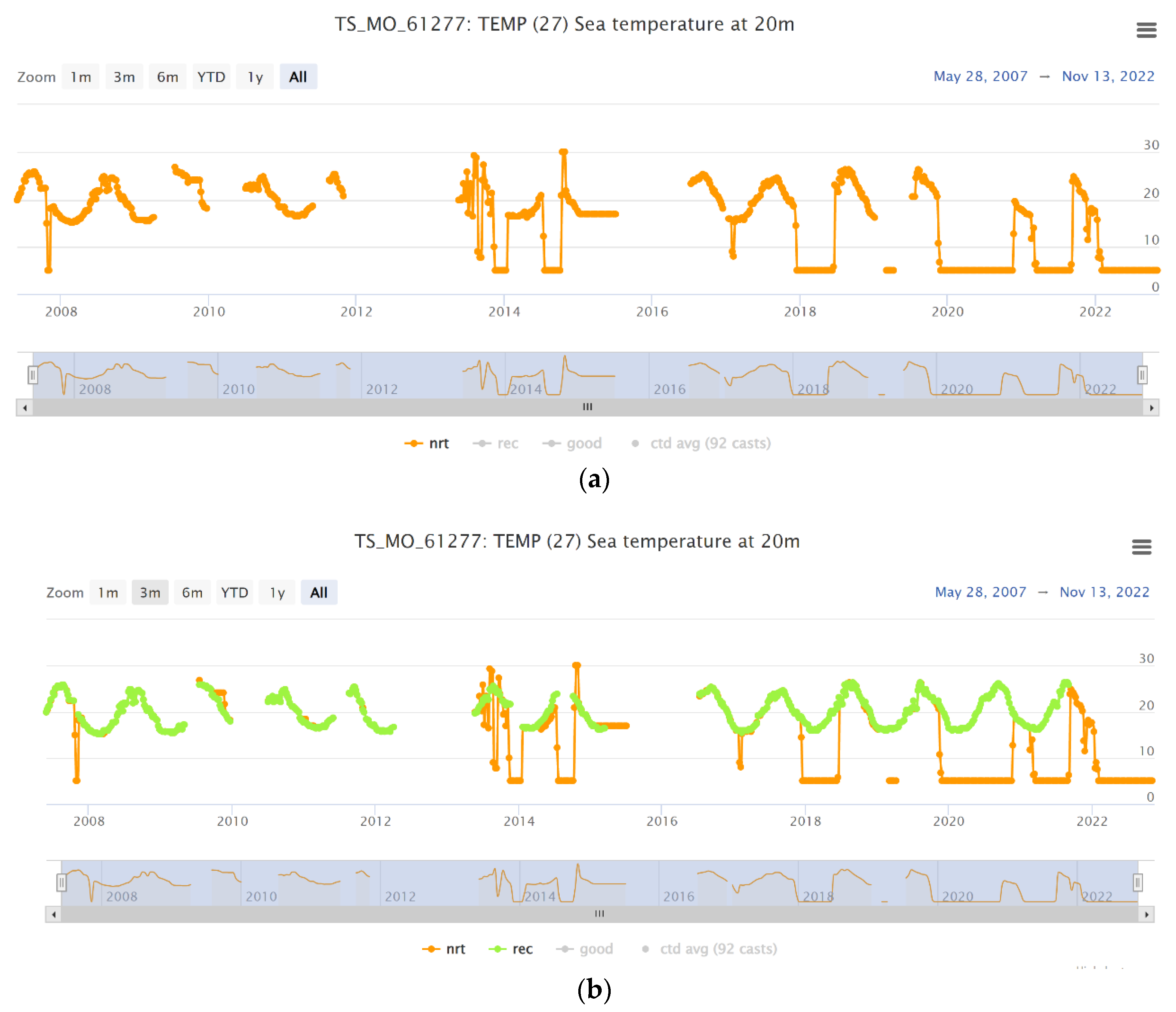
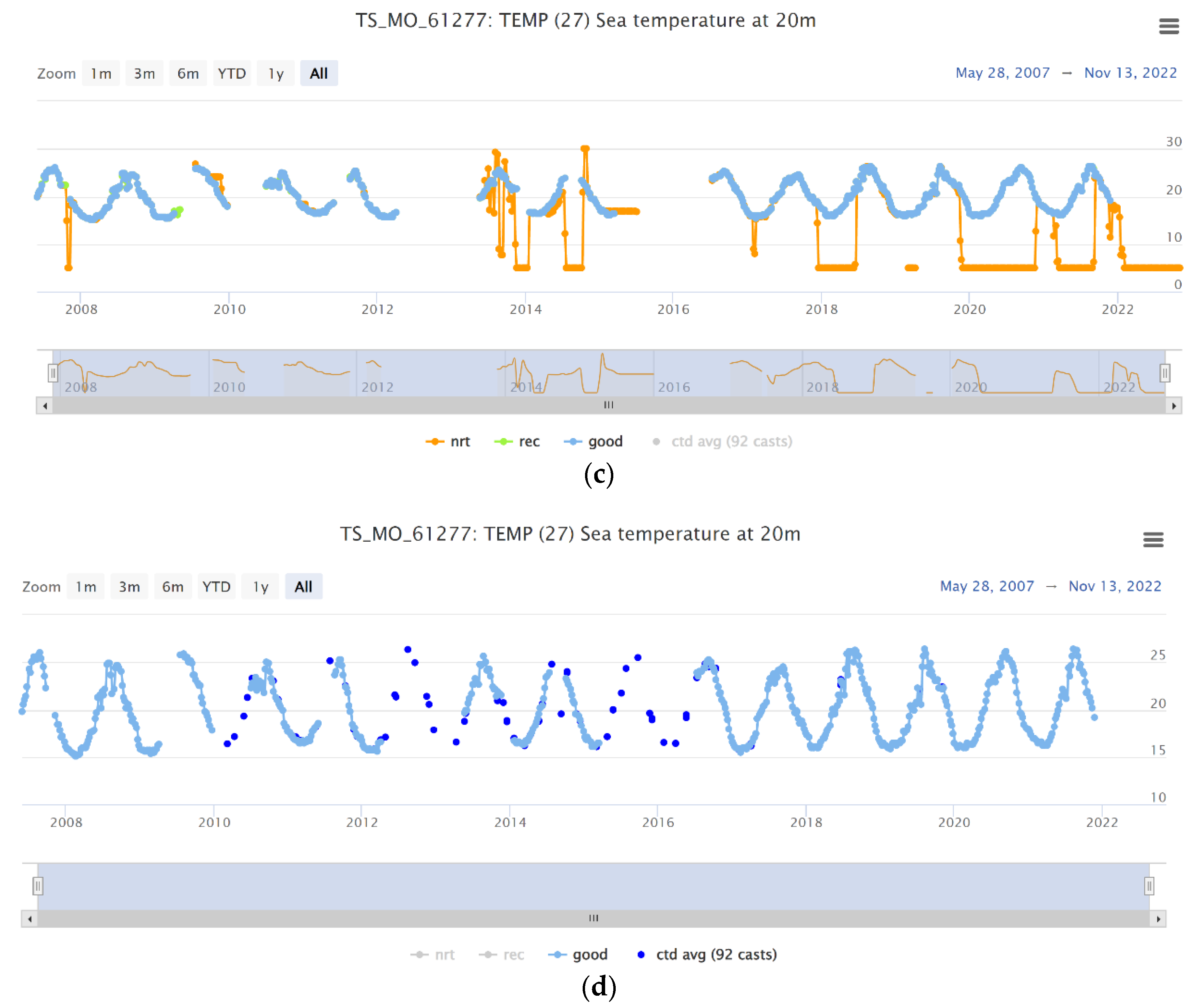
Figure 8. The POSEIDON buoys data flow using as an example the E1M3A 20 m temperature timeseries. Panel (a) corresponds to the NRT data received for the station during the deployment period. Panel (b) also includes the delayed mode data after the retrieval form the internal logger of the instrument and the process. Panel (c) presents the data after the first automated quality control, and panel (d)—the final data product after all the delayed quality control procedures and the field validation comparison.
Jmse 10 01932 g008aJmse 10 01932 g008b
Figure 9. Drifting incident for the ATHOS buoy, December 2013.
Jmse 10 01932 g009
Figure 10. In panel (a), the E1M3A buoy displays severe damage caused by a failed powerline, the buoy electronics and power container were destroyed by galvanic corrosion. (b) Inductive cable failure resulting in the loss of underwater telemetry. (c) A CTD recovered after 12 months of operation with external sensor cabling failures. (d) Failure of the screws in the head of an ADCP attached in the surface buoy, the result was the destruction of the sensor.
Jmse 10 01932 g010
Figure 11. The improvement of the salinity measurements after the replacement of the exposed surface sensor with one equipped with a pump and a flow-through system proven to be more effective against fouling.
Jmse 10 01932 g011
Figure 12. The multiparametric buoys of the Poseidon system (a). The mooring line diagram (b) corresponds to the E1M3A and PYLOS. The deployments depths of the sensors are 20, 50, 75, 100, 250, 400, 600 and 1000 m. The ATHOS buoy hosts sensor only for the first 100 m.
Jmse 10 01932 g012
Figure 13. E1M3A percentage of the quality-approved data, the rejected data during quality control (QC), as well as the percentage of non-operation periods of the station or sensors for temperature (a) and salinity (b).
Jmse 10 01932 g013
Figure 14. PYLOS percentage of the quality approved data, the rejected data during quality control (QC), as well as the percentage of non-operation periods of the station or sensors for temperature (a) and salinity (b).
Jmse 10 01932 g014
Figure 15. ATHOS percentage of the quality approved data, the rejected data during quality control (QC) as well as the percentage of non-operation period of the station or sensors for temperature (a) and salinity (b).
Jmse 10 01932 g015
Figure 16. The TAO Array Data Return for 2011–2022.
Jmse 10 01932 g016
Table 1. The parameters measured and transmitted in NRT for quality control and the oceanographic payload of the system platforms.
ParameterPlatform/Sampling FrequencySensorSensor TechnologyManufacturer Declared Accuracy/Sensitivity/Range
Temperature/Conductivity/PressureBuoys/180 minSBE 16plus-IMP C-T-P
SBE 37 IM C-T
Thermistor/Electrode Cell/Strain-gauge0.005 °C/0.0003 S m−1/0.1% of full scale range
Cabled obs/60 min
Ferrybox/1 minSBE 45
Glider/30 sSBE GPCTD
Argo float/NA
CurrentsBuoys/ 180 minNortek single point current meters/
Nortek profilers
Acoustic/ADCP0.5 cm s−1
HF Radar/30 minWERATransmission Frequency 16.15 MHzMaximun range 96 Km
WavesBuoys /180 minFugro Directional Wave Data SensorInertial sensorHeave, Surge, Sway <10 cm /Direction 0.3°/
Wave Period 2% of value
HF Radar/30 minWERATransmission Frequency 16.15 MHzMaximun range 96 Km
Sea levelTide gauges station/5 minOTT RLSPulse radar0.8–2 m: ± 10 mm
Fluorescence/
Turbidity
Buoys/180 minWetLabs FLNTUOptical0.025 µg L−1/0.013 NTU
Ferrybox/1 minScufa Turner FL0.02 µg L−1
Dissolved oxygenBuoys/180 minSBE 63Optical2%
Cabled obs/60 min
Ferrybox/1 minAanderaa Oxygen Optode 48355%
Table 2. The instrumentation of the PCL.
ParameterSensorAccuracyManufacturer
TemperatureSBE 350.001 °CSBE Electronics
Conductivity/SalinityAutoSal 8400 A0.003 pptGuildline Instruments
ConductivitySBE 37 SIP0.0003 S/mSBE Electronics
Dissolved oxygen39758 µMAanderaa
Table 3. The frequency of maintenance, the duration and the supporting means required per platform of the POSEIDON system.
PlatformMaintenance FrequencySupporting Means RequiredDuration
Fixed stations6–8 monthsResearch vessel
Land facilities
Diver support
8–15 days
FerryboxWeekly–monthlyLand facilities4–8 h
Cabled Seabed Observatory3 yearsResearch Vessel1 week
GliderMonthlyVessel to recover the glider
Land facilities
1 week
Table 4. The uncertainty of the temperature calibrations.
SourceManufacturer’s
Specification
Assumed ProbabilityObservedStandard Uncertainty
Temperature bath
stability
--0.0009 °C0.0009 °C
Temperature bath
homogeneity
--0.0012 °C0.0012 °C
Reference thermometer
stability
0.001 °Cy−1Rectangular-0.0006 °C
Reference thermometer
accuracy
0.001 °CRectangular-0.0006 °C
Combined standard
uncertainty
0.0017 °C
Expanded uncertainty (k = 2) 0.0034 °C
Table 5. Incidents of vandalism in the POSEIDON buoys.
Station NameDate of the IncidentIncidentImpact
HCBUnknownUnidentified ship collides with the station.The station meteo mast and sensors damaged
ATHOS29 September 2018Fishery activities close to the stationMooring line failure, emergency recovery
E1M3A14 May 2019Removal of surface equipment from the stationRecovered by the coast guard, the equipment included an active GPS tracker
Saronikos13 December 2019Fishery trawling activities close to the stationTotal loss of the station
Mykonos27 July 2020Failure of the mooring line caused by fishing equipment (hooks and fishing lines) attached to the mooring lineMooring line failure, emergency recovery
Publisher’s Note: MDPI stays neutral with regard to jurisdictional claims in published maps and institutional affiliations.