
Fatigue Strength Assessment of Single-Sided Girth Welds in Offshore Pipelines Subjected to Start-Up and Shut-Down Cycles


Abstract
:1. Introduction
2. Methods
2.1. Start-Up and Shut-Down Load Cycles
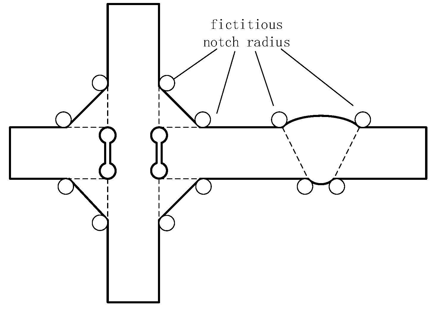
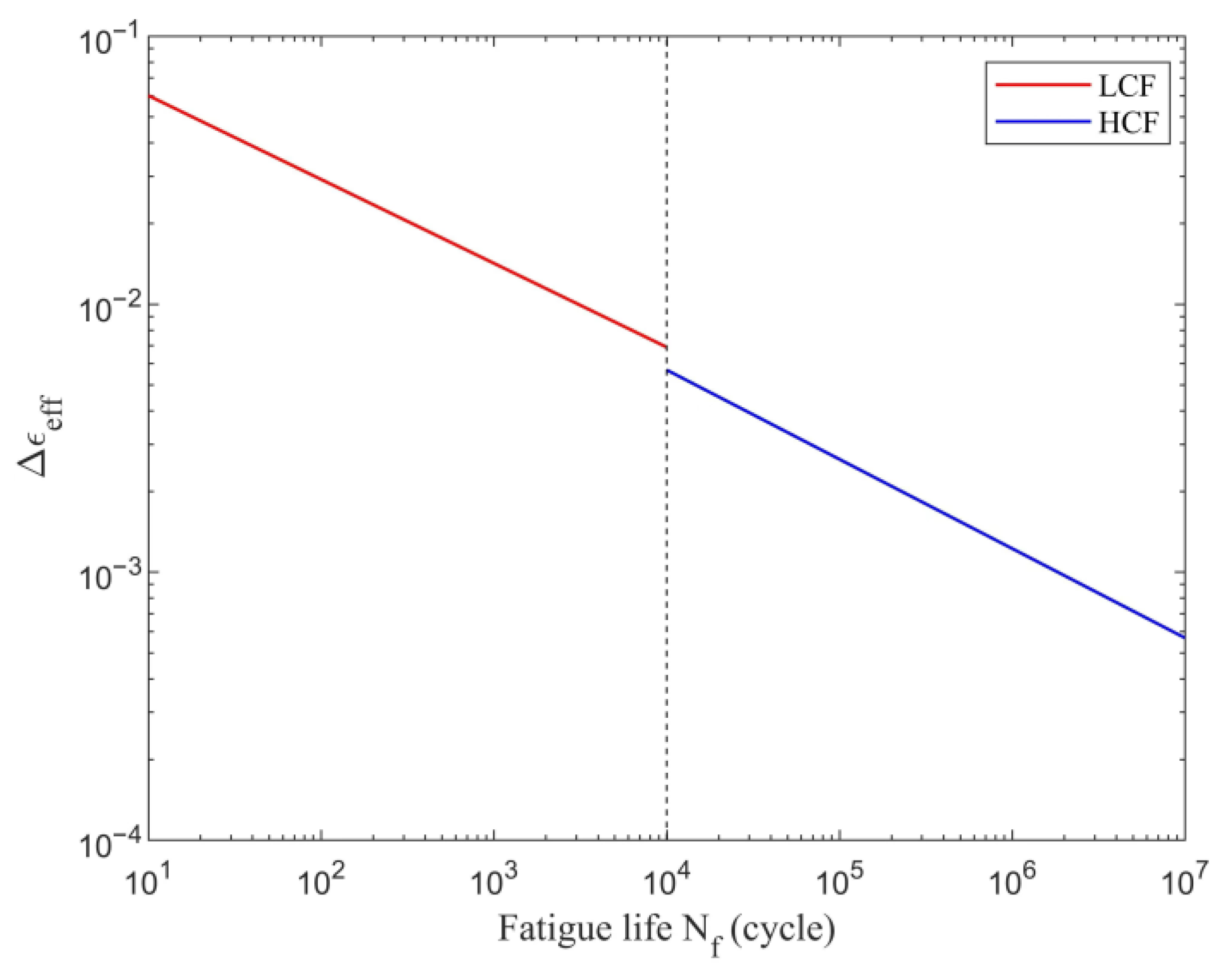
2.2. Fatigue Strength Assessment
3. Case Study
4. Results
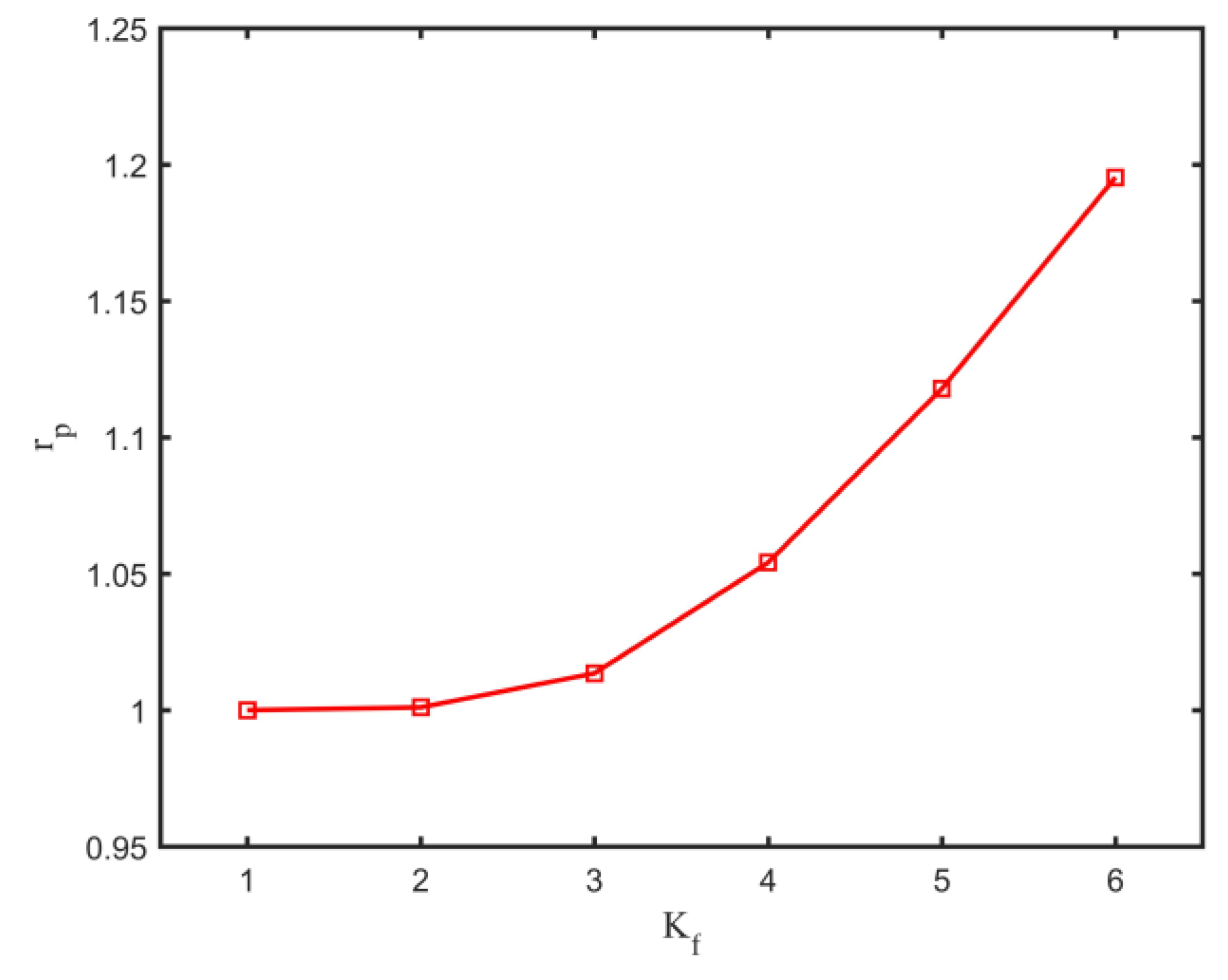
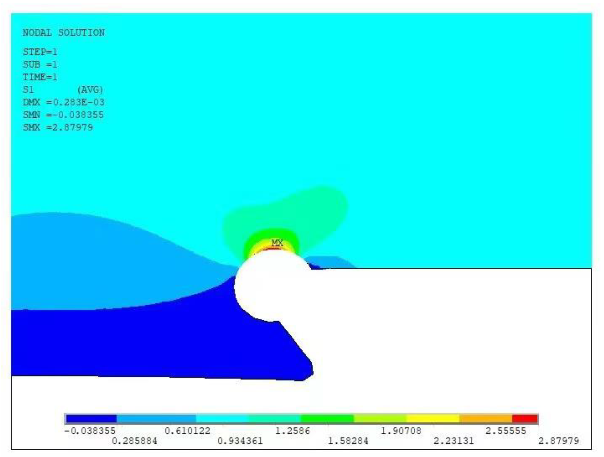
4.1. Plastic Behaviour
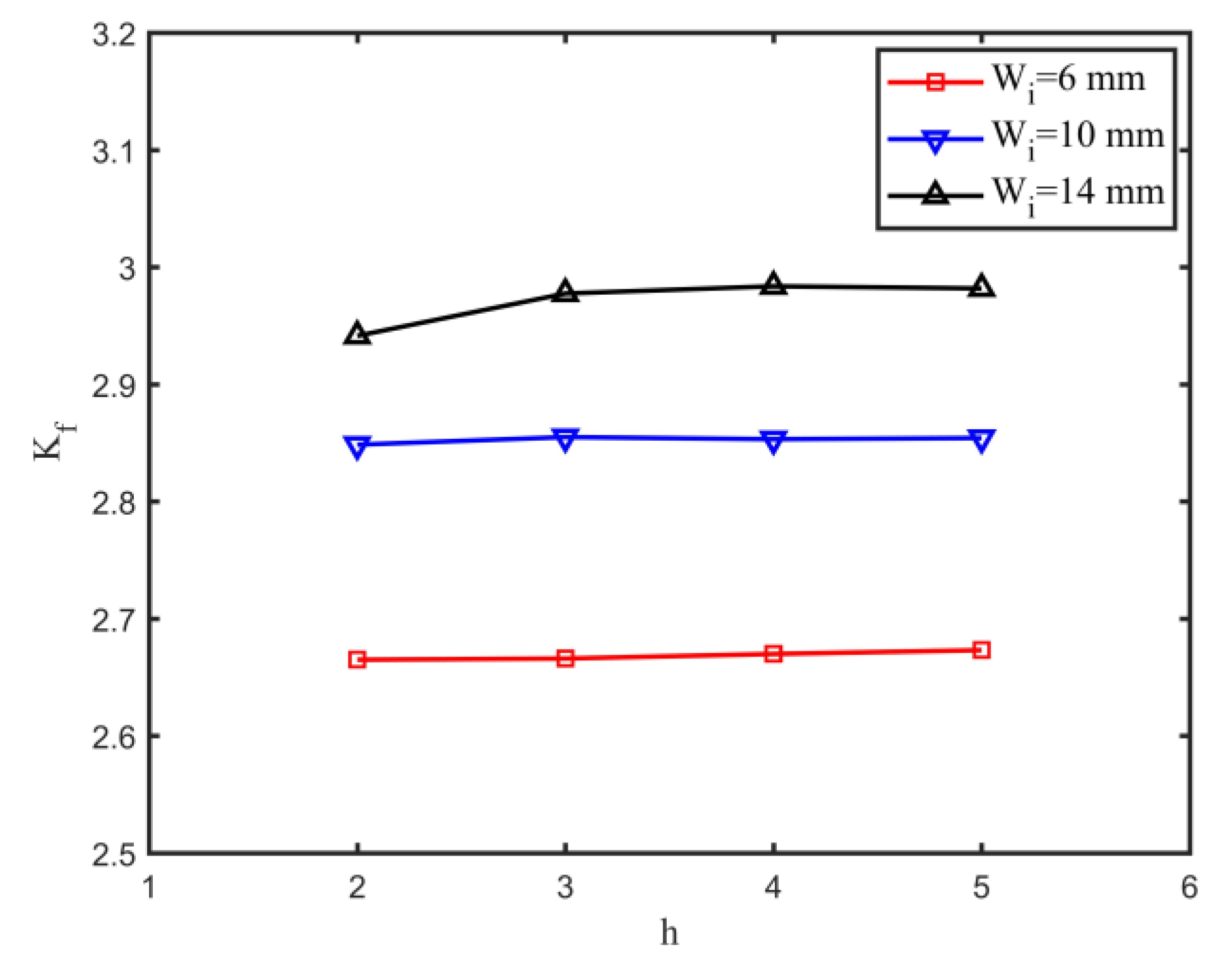
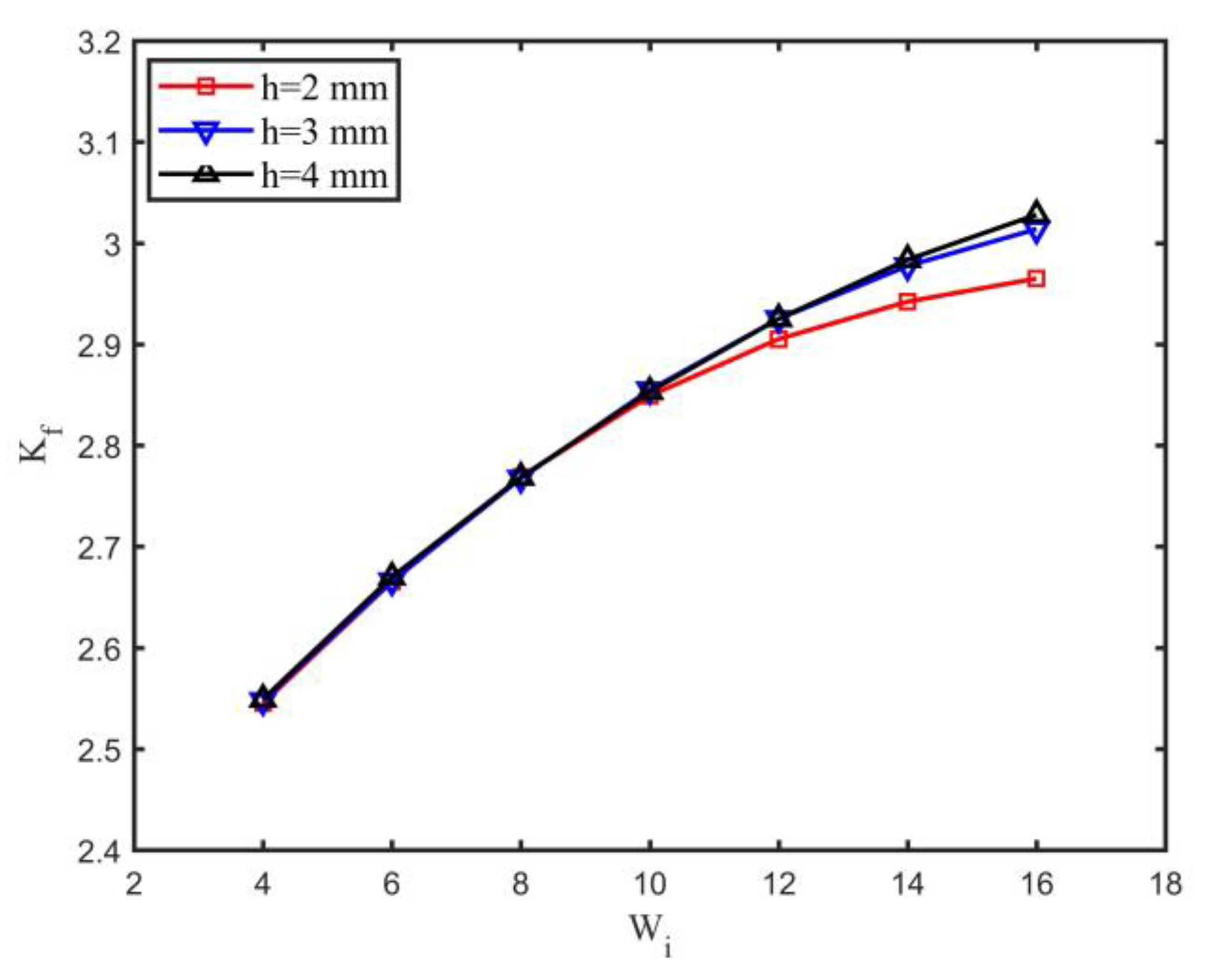
4.2. Effect of Weld Geometry
4.3. Fatigue Strength
5. Conclusions
- For the fully constrained condition, the longitudinal stress range due to start-up and shut-down cycles depends on the variation of internal pressure and temperature. Increasing the operating internal pressure and increasing the operating temperature has the opposite effect on the longitudinal stress range.
- For the study case, the plastic behaviour of the weld root is only significant for severe local stress concentrations. If the local stress concentration is kept at a low level, the HCF approach for fatigue strength assessment can also be used.
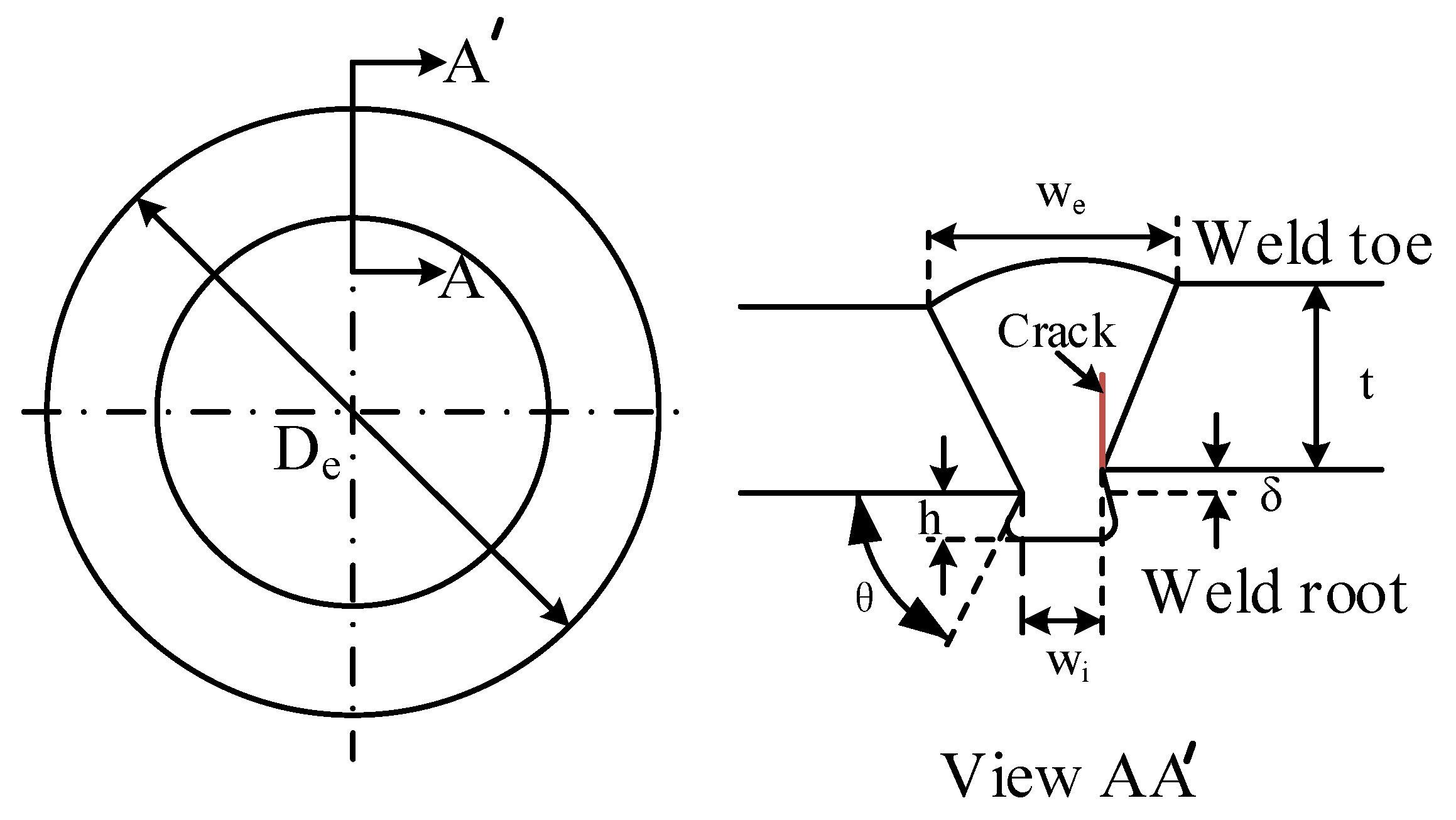
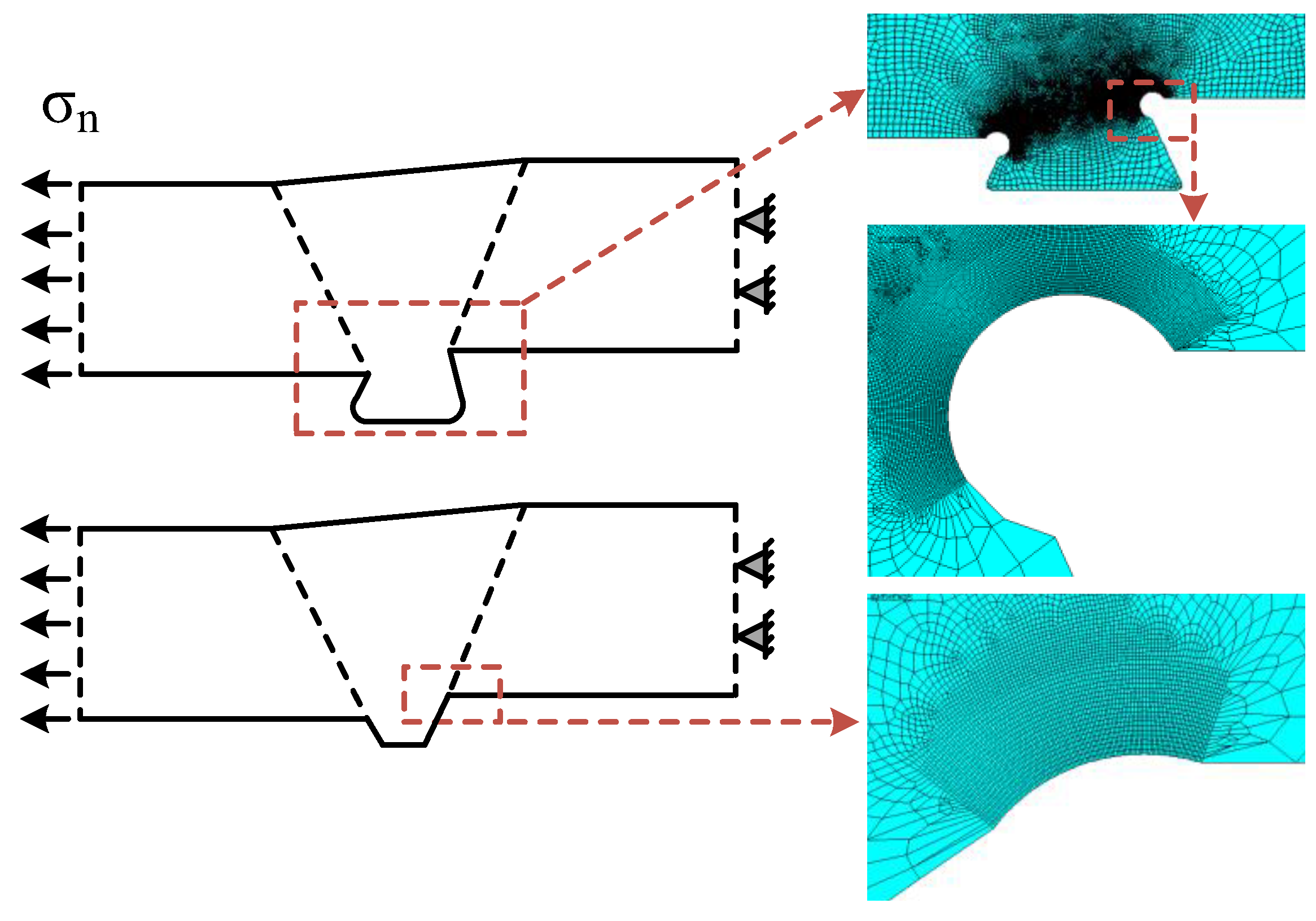
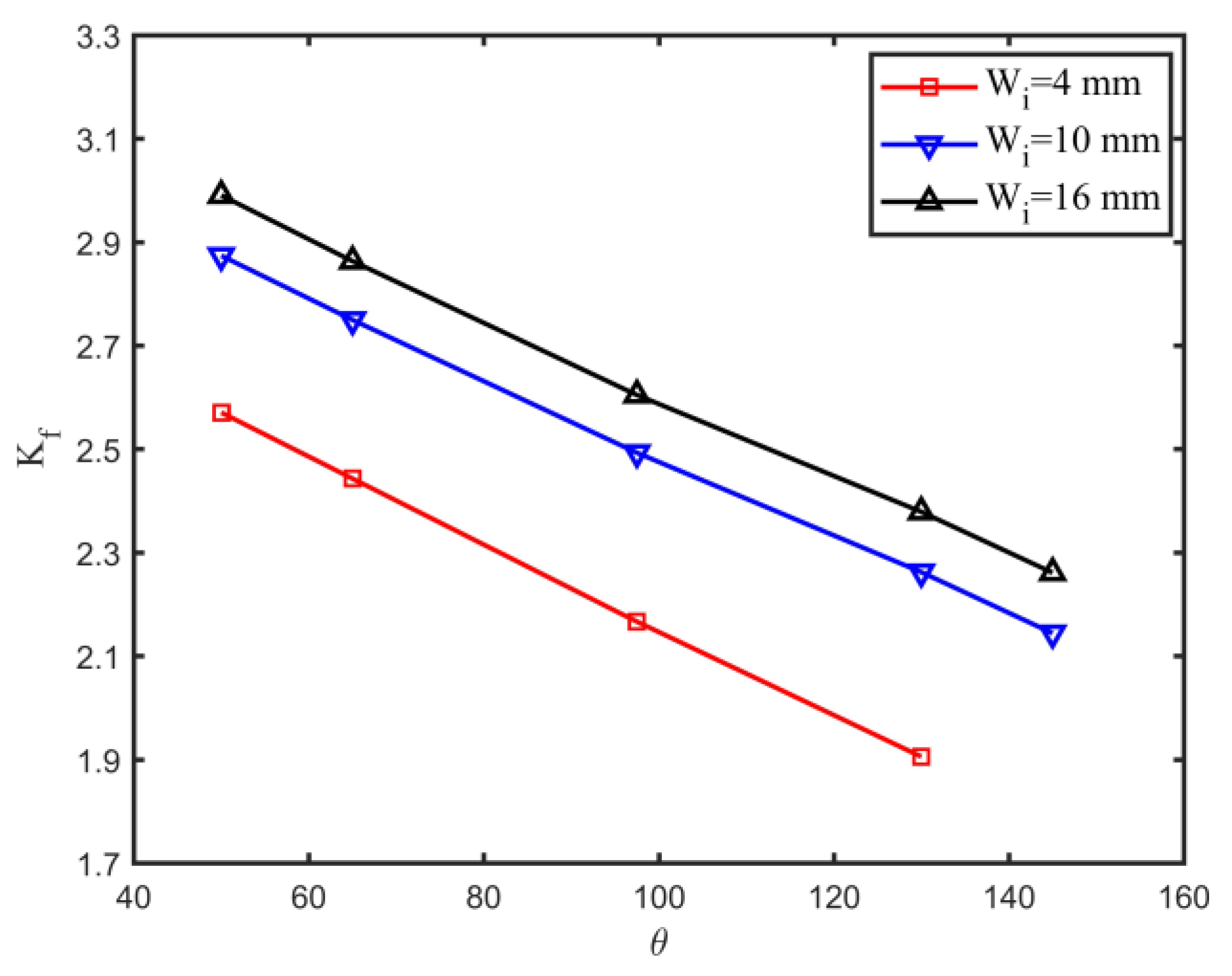
- For single-sided girth welds, the axial misalignment, weld root angle, and weld root bead width are the main geometrical parameters influencing the notch stress factor of the weld root.
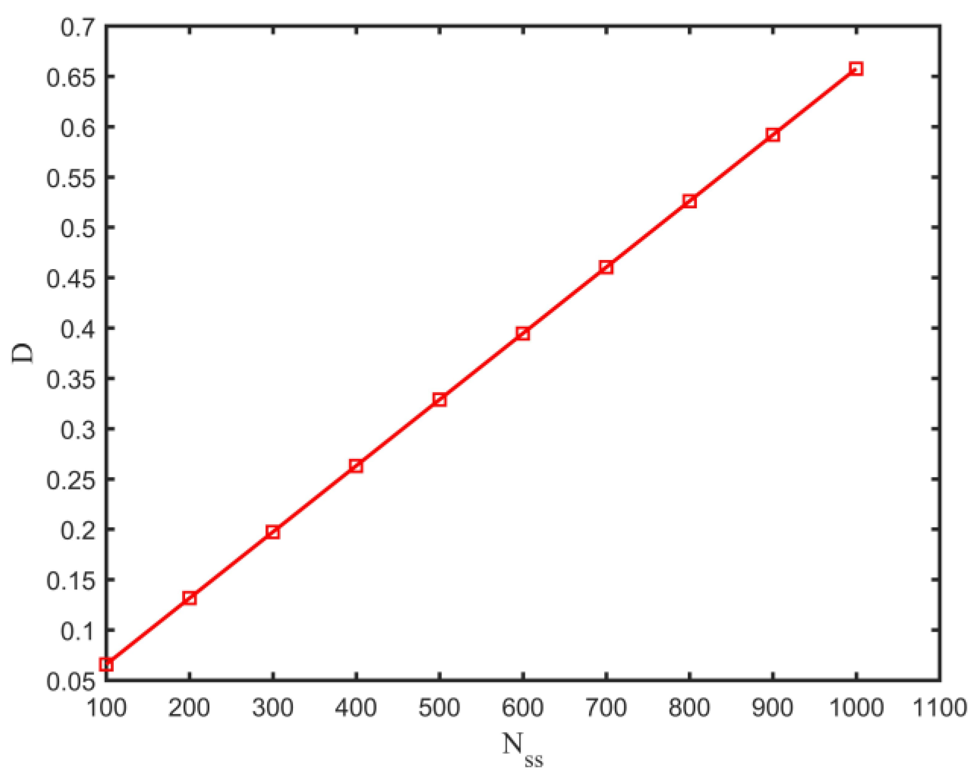
- If the fatigue damage at failure is 0.1, a limited number of start-up and shut-down cycles are allowed during the service life of the pipeline for the study case, indicating the necessity of fatigue strength assessment.
- There still exist some unsolved problems for the fatigue strength assessment of single-sided girth welds subjected to start-up and shut-down cycles. Some assumptions are made to simplify the fatigue problem and may be used in engineering practice. Further investigations are still required.
Author Contributions
Funding
Conflicts of Interest
Nomenclature
| Ae | External area of the pipe |
| Ai | Internal bore area of the pipe |
| As | Cross-sectional area of the pipe |
| C1, C2 | S-N curve parameters |
| E | Young’s modulus |
| FEM | Finite element method |
| Fres | Installation residual lay tension |
| HCF | High cycle fatigue |
| HPHT | High-pressure and high-temperature |
| h | Weld root bead height |
| K′ | Cyclic strength coefficient |
| Kf | Notch stress factor |
| LCF | Low cycle fatigue |
| m1, m2 | S-N curve parameters |
| Nf | Fatigue life |
| n′ | Cyclic strain hardening exponent |
| Pe | External pressure of the pipe |
| Pi | Operational internal pressure |
| Pi,ins | Internal pressure of the pipe during installation |
| rp | Ratio between Δεeff and Δεeff,e |
| Ta | Ambient temperature |
| Top | Operational temperature |
| t | Wall thickness |
| We | Weld toe bead width |
| Wi | Weld root bead width |
| α | Thermal expansion coefficient |
| μ | Generalised Poisson’s ratio |
| ν | Poisson’s ratio |
| Δεeff | Effective notch strain range |
| Δεeff,e | Elastic effective notch strain range |
| Δσl | Longitudinal stress range |
| Δσn | Nominal stress range |
| δ | Axial misalignment |
| θ | Weld root angle |
| ρf | Fictitious notch radius |
| σeff | Effective notch stress |
| σl | Longitudinal stress |
| σl,ins | Longitudinal stress for the installation condition |
| σl,op | Longitudinal stress for the operational condition |
References
- Bai, Q.; Bai, Y. Subsea Pipeline Design, Analysis, and Installation; Gulf Professional Publishing: Houston, TX, USA, 2014. [Google Scholar]
- Hong, Z.; Liu, R.; Liu, W.; Yan, S. A lateral global buckling failure envelope for a high temperature and high pressure (HT/HP) submarine pipeline. Appl. Ocean Res. 2015, 51, 117–128. [Google Scholar] [CrossRef]
- Carr, M.; Sinclair, F.; Bruton, D. Pipeline walking-understanding the field layout challenges, and analytical solutions developed for the SAFEBUCK JIP. In Proceedings of the Offshore Technology Conference, Houston, TX, USA, 1–4 May 2006. [Google Scholar]
- Hasan, S.; Sweet, L.; Hults, J.; Valbuena, G.; Singh, B. Corrosion risk-based subsea pipeline design. Int. J. Press. Vessel. Pip. 2018, 159, 1–14. [Google Scholar] [CrossRef]
- Bai, Q.; Pan, J. Pipeline Fatigue and Fracture Design. In Encyclopedia of Maritime and Offshore Engineering; John Wiley & Sons Ltd.: Hoboken, NJ, USA, 2017; pp. 1–18. [Google Scholar]
- Heo, J.; Kang, J.; Kim, Y.; Yoo, I.; Kim, K.; Urm, H. A study on the design guidance for low cycle fatigue in ship structures. In Proceedings of the 9th Symposium of Practical Design of Ships and Other Floating Structures, Luebeck-Travemuende, Germany, 12–17 September 2004. [Google Scholar]
- Wang, X.; Kang, J.-K.; Kim, Y.; Wirsching, P.H. Low cycle fatigue analysis of marine structures. In Proceedings of the ASME 2006 25th International Conference on Offshore Mechanics and Arctic Engineering, Hamburg, Germany, 4–9 June 2006; pp. 523–527. [Google Scholar]
- Dong, P.; Pei, X.; Xing, S.; Kim, M. A structural strain method for low-cycle fatigue evaluation of welded components. Int. J. Press. Vessel. Pip. 2014, 119, 39–51. [Google Scholar] [CrossRef]
- Pei, X.; Dong, P.; Xing, S. A structural strain parameter for a unified treatment of fatigue behaviors of welded components. Int. J. Fatigue 2019, 124, 444–460. [Google Scholar] [CrossRef]
- Lawrence, F.; Ho, N.; Mazumdar, P.K. Predicting the fatigue resistance of welds. Annu. Rev. Mater. Sci. 1981, 11, 401–425. [Google Scholar] [CrossRef]
- Dong, Y.; Garbatov, Y.; Guedes Soares, C. Strain-based fatigue reliability assessment of welded joints in ship structures. Mar. Struct. 2021, 75, 102878. [Google Scholar] [CrossRef]
- Saiprasertkit, K.; Hanji, T.; Miki, C. Fatigue strength assessment of load-carrying cruciform joints with material mismatching in low-and high-cycle fatigue regions based on the effective notch concept. Int. J. Fatigue 2012, 40, 120–128. [Google Scholar] [CrossRef]
- Dong, Y.; Garbatov, Y.; Guedes Soares, C. Improved effective notch strain approach for fatigue reliability assessment of load-carrying fillet welded cruciform joints in low and high cycle fatigue. Mar. Struct. 2021, 75, 102849. [Google Scholar] [CrossRef]
- Ngoula, D.T.; Beier, H.T.; Vormwald, M. Fatigue crack growth in cruciform welded joints: Influence of residual stresses and of the weld toe geometry. Int. J. Fatigue 2017, 101, 253–262. [Google Scholar] [CrossRef]
- Hutař, P.; Poduška, J.; Šmíd, M.; Kuběna, I.; Chlupová, A.; Náhlík, L.; Polák, J.; Kruml, T. Short fatigue crack behaviour under low cycle fatigue regime. Int. J. Fatigue 2017, 103, 207–215. [Google Scholar] [CrossRef]
- Cheng, A.; Chen, N.-Z.; Pu, Y.; Yu, J. Fatigue crack growth prediction for small-scale yielding (SSY) and non-SSY conditions. Int. J. Fatigue 2020, 139, 105768. [Google Scholar] [CrossRef]
- Cheng, A.; Chen, N.-Z. Structural integrity assessment for deep-water subsea pipelines. Int. J. Press. Vessel. Pip. 2022, 199, 104711. [Google Scholar] [CrossRef]
- Schweizer, C.; Seifert, T.; Nieweg, B.; Von Hartrott, P.; Riedel, H. Mechanisms and modelling of fatigue crack growth under combined low and high cycle fatigue loading. Int. J. Fatigue 2011, 33, 194–202. [Google Scholar] [CrossRef]
- Deng, J.; Yang, P.; Dong, Q.; Wang, D. Research on CTOD for low-cycle fatigue analysis of central-through cracked plates considering accumulative plastic strain. Eng. Fract. Mech. 2016, 154, 128–139. [Google Scholar] [CrossRef]
- Fricke, W. IIW Recommendations for the Fatigue Assessment of Welded Structures by Notch Stress Analysis: IIW-2006-09; Woodhead Publishing: Shaston, UK, 2012. [Google Scholar]
- Glinka, G. Calculation of inelastic notch-tip strain-stress histories under cyclic loading. Eng Fract Mech 1985, 22, 839–854. [Google Scholar] [CrossRef]
- Glinka, G. Energy density approach to calculation of inelastic strain-stress near notches and cracks. Eng. Fract. Mech. 1985, 22, 485–508. [Google Scholar] [CrossRef]
- Dowling, N.E. Mechanical Behavior of Materials: Engineering Methods for Deformation, Fracture, and Fatigue; Pearson: London, UK, 2013. [Google Scholar]
- Fatoba, O.; Akid, R. Low cycle fatigue behaviour of API 5L X65 pipeline steel at room temperature. Procedia Eng. 2014, 74, 279–286. [Google Scholar] [CrossRef]
- Dong, Y.; Garbatov, Y.; Guedes Soares, C. Fatigue strength assessment of an annealed butt welded joint accounting for material inhomogeneity. In Progress in the Analysis and Design of Marine Structures; Guedes Soares, C., Garbatov, Y., Eds.; Taylor & Francis Group: London, UK, 2017; pp. 349–359. [Google Scholar]
- Horn, A.M.; Lotsberg, I.; Orjaseater, O. The rationale for update of SN curves for single sided girth welds for risers and pipelines in DNV GL RP C-203 based on fatigue performance of more than 1700 full scale fatigue test results. In Proceedings of the International Conference on Ocean, Offshore and Arctic Engineering (OMAE), Madrid, Spain, 17–22 June 2018. [Google Scholar]
- Zhang, Y.-H.; London, T.; DeBono, D. Developing Mk Solutions for Fatigue Crack Growth Assessment of Flaws at Weld Root Toes in Girth Welds. In Proceedings of the International Conference on Offshore Mechanics and Arctic Engineering, Madrid, Spain, 17–22 June 2018. [Google Scholar]
- Dong, Y.; Kong, X.; An, G.; Kang, J. Fatigue reliability of single-sided girth welds in offshore pipelines and risers accounting for non-destructive inspection. Mar. Struct. 2022, 86, 103268. [Google Scholar] [CrossRef]
- ANSYS. Online Manuals. 2012.
- Dong, Y.; Teixeira, A.P.; Guedes Soares, C. Fatigue reliability analysis of butt welded joints with misalignments based on hotspot stress approach. Mar. Struct. 2019, 65, 215–228. [Google Scholar] [CrossRef]
- Hobbacher, A. Recommendations for Fatigue Design of Welded Joints and Components; Springer: Berlin/Heidelberg, Germany, 2015. [Google Scholar]
- DNVGL. Fatigue Design of Offshore Steel Structures; Det Norske Veritas: Hovik, Norway, 2016; Volume DNVGL-RP-C203. [Google Scholar]


| S-N Curve Parameter | Value |
|---|---|
| C1 | 1.25 × 10⁻³ |
| m1 | 3.195 |
| C2 | 1.83 × 10⁻³ |
| m2 | 3 |
| Modelling Parameters | Unit | Value |
|---|---|---|
| Pipeline outer diameter, De | mm | 355.6 |
| Pipeline wall thickness, t | mm | 19.8 |
| Area of steel pipeline’s cross-section, As | m2 | 0.0209 |
| Internal pressure of installation/shut-down, Pi,ins | MPa | 2 |
| Operating internal pressure, Pi | MPa | 20 |
| Operating temperature, Top | °C | 120 |
| Seabed ambient temperature, Ta | °C | 12 |
| Coefficient of thermal expansion, α | °C−1 | 1.3 × 10⁻⁵ |
| Young’s modulus, E | MPa | 2.06 × 10⁵ |
| Poisson’s ratio, ν | - | 0.3 |
| Cyclic strength coefficient, K′ | MPa | 923 |
| Cyclic strain hardening exponent, n′ | - | 0.118 |
| Geometrical Parameters | Unit | Value |
|---|---|---|
| Weld root bead width, Wi | mm | 4, 6, 8, 10, 12, 14, 16 |
| Weld root bead height, h | mm | 2, 3, 4, 5 |
| Weld root angle, θ | ° | 50, 65, 97.5, 130, 145 |
| Axial misalignment, δ | mm | 0, 1, 2, 3 |
Publisher’s Note: MDPI stays neutral with regard to jurisdictional claims in published maps and institutional affiliations. |
© 2022 by the authors. Licensee MDPI, Basel, Switzerland. This article is an open access article distributed under the terms and conditions of the Creative Commons Attribution (CC BY) license (https://creativecommons.org/licenses/by/4.0/).
Share and Cite
Dong, Y.; Ji, G.; Fang, L.; Liu, X. Fatigue Strength Assessment of Single-Sided Girth Welds in Offshore Pipelines Subjected to Start-Up and Shut-Down Cycles. J. Mar. Sci. Eng. 2022, 10, 1879. https://doi.org/10.3390/jmse10121879
Dong Y, Ji G, Fang L, Liu X. Fatigue Strength Assessment of Single-Sided Girth Welds in Offshore Pipelines Subjected to Start-Up and Shut-Down Cycles. Journal of Marine Science and Engineering. 2022; 10(12):1879. https://doi.org/10.3390/jmse10121879
Chicago/Turabian StyleDong, Yan, Guanglei Ji, Lin Fang, and Xin Liu. 2022. "Fatigue Strength Assessment of Single-Sided Girth Welds in Offshore Pipelines Subjected to Start-Up and Shut-Down Cycles" Journal of Marine Science and Engineering 10, no. 12: 1879. https://doi.org/10.3390/jmse10121879
APA StyleDong, Y., Ji, G., Fang, L., & Liu, X. (2022). Fatigue Strength Assessment of Single-Sided Girth Welds in Offshore Pipelines Subjected to Start-Up and Shut-Down Cycles. Journal of Marine Science and Engineering, 10(12), 1879. https://doi.org/10.3390/jmse10121879