Article

Dynamic Response of DP Offshore Platform-Riser Multi-Body System Based on UKF-PID Control

1
Ship and Maritime College, Guangdong Ocean University, Zhanjiang 524088, China
2
Ocean College, Zhejiang University, Zhoushan 316021, China
3
College of Civil Engineering, Zhejiang University, Zhoushan 316000, China
4
Faculty of Maritime and Transportation, Ningbo University, Ningbo 315211, China
*
Author to whom correspondence should be addressed.
J. Mar. Sci. Eng. 2022, 10(11), 1596; https://doi.org/10.3390/jmse10111596
Submission received: 26 September 2022 / Revised: 25 October 2022 / Accepted: 25 October 2022 / Published: 28 October 2022
(This article belongs to the Special Issue Subsea Pipelines)

Abstract

:
The coupling effect between the offshore platform and the riser in the offshore platform-riser multi-body system might be greatly increased under heavy external maritime stresses. The system will become significantly more nonlinear. The partial secondary development of OrcaFlex is carried out considering the strong non-linearity of the dynamic positioning (DP) offshore platform-riser multi-body system, combined with the actual offshore construction engineering background and the lumped mass method, based on Python-language embedded programming with the basis of the operation principle of the application program interface (API) and the composition of its modules. To regulate the dynamic positioning of the offshore platform-riser multi-body coupling system, a UKF-PID control approach based on an unscented Kalman filter is presented. Based on the procedures described above, a classical calculation model is created, and the model’s calculation results are compared to those of relevant references, confirming the method’s validity and viability. Finally, the model of the PID-controlled dynamic positioning offshore platform-riser rigid–flexible multi-body system is developed, and a dynamic simulation is performed under specified sea conditions. The findings have implications for engineering practice.

1. Introduction

Large maritime constructions like floating offshore platforms and special engineering vessels that float in the water might typically have their location and spatial attitude determined by empirical calculations based on heading angles, velocity, and ocean currents [1,2,3,4]. In fact, the changes in a ship’s position that can be roughly calculated by empirical formulas are not timely and not accurate enough, and for some construction projects that require high accuracy and fast feedback speed, they are far from meeting their technical requirements [5,6,7]. This is due to the instantaneity of wind, wave, and current load changes in the time domain, the randomness and mutability of changes in the height direction, and the changes in a ship’s position that can be roughly calculated by empirical formulas [8,9,10]. The dynamic response of offshore platforms is nonlinear, time-varying, and uncertain, so it is a very difficult task to control the motion of ships and offshore platforms in actual engineering operations [11]. The dynamic positioning system is very important for the safety of ships and offshore platforms, especially large vessels and offshore platforms [12,13,14,15].
To put it simply, the dynamic positioning of an offshore platform is when the ship or offshore platform is at a low speed and the controller calculates three assumed values of longitudinal force, lateral force, and rotational torque [16]. The assumed forces and torques obtained from the controller are processed and transferred to the required propeller parameters, such as the propeller speed, blade setting angle, rudder angle, and propeller azimuth angle. Then, in combination with specific construction requirements, the position, angle, and space attitude of the ship or offshore platform are effectively adjusted. The dynamic positioning system has been developed to some extent. For, example, Fossen and Pettersen [17] suggested an underwater vehicle theory, asserting that the underwater vehicle’s six-degrees-of-freedom dynamic positioning control was accomplished. They discovered that, as compared to surface dynamic positioning, additional degrees of freedom of underwater vehicles should be considered in dynamic positioning control due to the unpredictability of the underwater current and the wave and current stresses on the vehicles. In a subsequent study, Fossen [18] explicitly stated that in the motion operation of certain ships, due to the presence of many thrusters, the needed control actions could be executed in a variety of ways; other combinations of actuators can also provide the same control actions. To prevent linearization of the ship motion equation, it can be attempted to apply nonlinear control to the dynamic positioning system. Grovelen and Fossen [19] offered vector inversion as a viable solution to difficulties in dynamic positioning system control. This system is based on the effective filtering of measured ship position and heading data, with only white noise added as interference. The signals will, however, also be impacted in practical engineering applications by the waves hitting the hull. Thus, filtering is carried out using a so-called filtering technique before the calculated speed estimate is imported into the feedback loop. This involves extracting the wave frequency from the measured motion so that the controller can only obtain low-frequency signals and filter out high-frequency motion components and measurement noise. A motion control experiment on the motion of a physical model of a ship, Cybership II, was carried out in a shallow water tank at a laboratory in Trondheim to check the accuracy of Skjetne and Fossen’s [20] adaptive control theory. The experimental results suggest that their hypothesis is quite useful in shallow water. Gierusz (2007) effectively built and evaluated a ship control system consisting of two separate controllers. It was discovered that the ship control system composed of these two controllers may increase the efficiency in a certain operation area.
A type of controller created by Morawski and Nguyen Cong [21] employs fuzzy logic to regulate the motion of the ship in the port. The adjustment and control of the ship’s motion attitude in a confined space both benefit from this controller. Lee et al. examined the control effectiveness and control quality of a PID controller and a fuzzy controller throughout the process of a ship entering a port. They also outlined the benefits and drawbacks of the two control strategies [22]. Bui et al. suggested a technique to regulate the motions of four tugs throughout the maneuvering operation at the port [23]. By considering the filtering and reconstruction of low-frequency motion components, Fossen and Strand created an observer for dynamic positioning systems [24]. Asgeir J. Srensen et al. [25] developed a novel approach based on the design of the typical mooring auxiliary dynamic positioning FPSO, and the preliminary concepts put forward have been used to counteract the negative impacts of hazardous sea conditions on the placement of FPSO. Johann Wichers et al. [26] examined the use of mooring-assisted dynamic positioning for an FPSO in deep water and proposed a concept of an optimized design based on their study. Aalbers et al. [27] performed a hydrodynamic model test on a dynamically positioned ship under closed-loop control, which effectively tested the performance of the closed-loop system and determined the hydrodynamic parameters of the model ship under the action of the dynamic positioning system.
The method for studying the dynamic response of a DP offshore platform-riser multi-body system mainly focuses on the combination of numerical simulation and experiment. Sorheim [28] carried out computer modeling and simulations for a DP oil tanker under single-point mooring and preliminarily realized the computer simulations of the coupling response between the DP offshore platform and risers. The research showed that the thrust distribution of the DP offshore platform-riser multi-body system has a significant impact on the tension of the mooring system and the distribution of tension on each mooring line. By reasonably distributing the thrust of the DP platform’s thrusters, the mooring tension borne by the mooring lines can be greatly reduced, thereby avoiding the conflict between the thrust system and the mooring system and improving the flexibility of the whole system. Wichers et al. [29] also conducted numerical simulations and experimental verification on the DP oil tanker under single-point mooring and found that the low-frequency partial viscous damping played an important role in the oscillating motion of the DP oil tanker. Lopez et al. [30] provides a description of the FPSO hull and station keeping system and the disconnectable turret-riser system and presented the preliminary results from a design study. Tannuri et al. [31] investigated how a large shuttle tanker responded dynamically to a dynamic positioning system. The above research mainly focuses on the interaction between the DP offshore platform and mooring lines. There are some differences between mooring lines and risers [32,33,34,35]. The bending stiffness and torsional stiffness of mooring lines are very small. For the risers with a certain bending stiffness and torsional stiffness, there is a certain difference between the risers and mooring lines [36]. Regarding the interaction between the riser and the platform or the underwater vehicles, Mai-The Vu [37,38,39,40,41] and Hyeung-Sik Choi [42,43,44,45,46] conducted a lot of research. A study on the hovering motion of an underwater vehicle with an umbilical cable was carried out by Mai-The Vu and Hyeung-Sik Choi [47,48]. A new full dynamics equation on the combined motions of the underwater vehicle and the umbilical cable was presented to analyze the dynamic performance of the underwater vehicle motion. The simulation results showed that the umbilical cable significantly affected the motion of the underwater vehicle during forward motion, sideward motion, and turning motion. However, the effect of the umbilical cable on the underwater vehicle motion during ascending motion was less significant, since the buoyancy force of the umbilical cable was assumed to be zero.
According to Wang et al. [49], the presence of a DP system can minimize mooring line stress and increase the positioning accuracy of dynamic positioning ships. However, when the external load and the rigid–flexible coupling degree grow in the rigid–flexible multi-body system of an offshore platform-riser, the nonlinearity of the entire system will increase. As a result, a novel control strategy that is more applicable under severe nonlinear situations is required. In this paper, a new PID control approach based on the unscented Kalman filter for the dynamic positioning offshore platform-riser multi-body system is created by merging the unscented Kalman filter with the traditional PID control, and the DP control of a rigid–flexible fluid coupling system composed of an offshore platform and risers is realized. Considering the influence of different control modes on the whole rigid–flexible multi-body coupling system, based on the offshore platform-riser multi-body system without a dynamic positioning system, the dynamic analysis model of the offshore platform-riser multi-body system under single PID control mode and unscented Kalman filter-PID (UKF-PID) control mode is established and compared. The rest of this paper is organized as follows. Section 2 introduces the PID control method and dynamic modeling of the DP offshore platform based on the unscented Kalman filter (UKF) in Python language. Section 3 verifies the correctness and reliability of the dynamic analysis model. Section 4 presents the results and discussion. Finally, the conclusions drawn from this paper are presented in Section 5.

2. Methodology

2.1. PID Control Method

Although there are many different process control methods, PID control is still the best option because of its smaller structural loop and higher resilience. However, the limited stability of the PID control is still a drawback. It is necessary to develop a PID control system based on the Kalman filter in order to enhance the system’s compatibility and stability and make the response more reliable and accurate. The final form of the PID algorithm can be expressed as follows:
u ( t ) = K p e ( t ) + K i 0 t e ( τ ) d τ + K d d e ( t ) d t
where Kp is the proportional gain, Ki is the integral gain, and Kd is the differential gain.

2.2. Unscented Kalman Filter Algorithm and Its Principle

The ideal state of a dynamic system may be determined via Kalman filtering. Even if the observed system state parameters contain noise and the observed values are not precise enough, Kalman filtering can complete the relative optimum estimation of the real-state value. It consists of the standard Kalman filter (KF), the extended Kalman filter (EKF), and the unscented Kalman filter (UKF). However, for non-linear situations, whether KF or EKF, there are issues with massive quantities of computations, and linear mistakes can easily influence the model’s accuracy. As a result, the unscented transformation (an approximation approach for finding the moments of each order of nonlinear random variables, UT) may be introduced to tackle this problem based on the classic Kalman filter. It obtains the average value and variance mostly by frequent sampling and weighting, which employs the unscented Kalman filter (UKF). The impact of UKF can potentially produce effects that only second-order EKF is capable of producing since this approach has a greater approximation accuracy for statistical moments.
The guiding ideology of UT ensures that the mean and covariance of system sampling are x ¯ and Pxx, respectively. Then, a set of sigma points is selected, and the nonlinear transformation is applied to the sigma points of each sampling data to obtain the point set y ¯ and Pyy for the nonlinear transformation.
In the traditional sense, the algorithm of UT transformation is as follows.
According to the statistics of input variables x ¯ and Pxx, a sigma point set {Xi} under a sampling strategy (i = 0, 1, 2, …, 2n), and the corresponding weights Wim and Wic are selected, where i is the number of sigma points, Wim is the weight used for mean weighting, and Wic is the weight used for covariance weighting. Without proportional correction, Wim = Wic= Wi.
The corresponding weight Wi of 2n + 1 sampling points is calculated:
X 0 = x ¯ , W 0 = σ n + σ i = 0
X i = x ¯ + ( ( n + σ ) P x x ) i , W i = 1 2 ( n + σ ) i = 1 , , n
X i = x ¯ ( ( n + σ ) P x x ) i , W i = 1 2 ( n + σ ) i = n + 1 , , 2 n
where σ is a fine-tuning parameter, which can only affect the deviation caused by the higher order moment after the second order; ( ( n + σ ) P x x ) i is the ith row or the ith column vector of the square root of the matrix ( n + σ ) P x x , which can be calculated by Cholesky decomposition; Wi is the weight of the ith sigma point.
i = 0 2 n W i = 1
The square root of matrix P can be decomposed by Cholesky, which makes the calculation more stable and efficient. The sigma points { y i } of the sampled data are transformed nonlinearly under the following equation:
y i = f ( x i ) i = 0 , 2 n
After weighting the point set { y i } obtained by the new transformation, the statistics y ¯ and Pyy of the output variable y are obtained.
y ¯ = i = 0 2 n W i m y i P y y = i = 0 2 n W ( y i y i ¯ ) i c ( y i y i ¯ ) T
Combined with the UT transform described above to deal with the non-linear transfer of mean and covariance, the UKF algorithm can be realized. Due to the noise factor, the state equation for the system must be enlarged in the UKF algorithm.
x a = [ x T , v T , n T ] T is taken as the state estimation at k-time, and the specific algorithm flow is as follows:
x ^ = E ( x 0 )
P 0 = E ( ( x 0 x ^ 0 ) ( x 0 x ^ 0 ) T )
Then, extend the initial condition of the state:
x ^ 0 a = E ( x 0 a ) = [ x ^ 0 a ; 0 , 0 ]
P 0 a = E ( ( x 0 a x ^ 0 a ) ( x 0 a x ^ 0 a ) T ) = [ P 0 0 0 0 Q 0 0 0 R ]
Next, through an appropriate sampling strategy, the state estimation sigma point set at k-time is obtained (i = 0, 1, 2, …, 2n), and i is the number of sigma points of the sampled data. It should be noted that the state dimension is n + q + m and Xix is the column vector composed of the n dimensions of Xia; is the column vector from n + 1 to n + q dimensions of Xia; and Xiw is the column vector from n + q + 1 to n + q + m dimensions of Xia. The sampling points will then be transferred using the system’s state equation:
X i x ( k + 1 | k ) = f [ X i k ( k | k ) , u ( k ) , X i v ]
As the transfer sampling is completed, the prediction sampling point X i x ( k + 1 | k ) , weighting Wim and Wic, is used to calculate the predicted mean x ^ ( k + 1 | k ) and covariance P ( k + 1 | k ) .
x ^ ( k + 1 | k ) = i = 0 2 n W i m X i x ( k + 1 | k )
P ( k + 1 | k ) = i = 0 2 n W i c ( X i x ( k + 1 | k ) x ^ ( k + 1 | k ) ) ( ) T
The predicted forecast measurement sampling points can be expressed as:
z i ( k + 1 | k ) = h [ X i x ( k + 1 | k ) , u ( k ) , X i w ( k + 1 ) ]
Then, predict the measured value and covariance:
z ^ ( k + 1 | k ) = i = 0 2 n W i m z i ( k + 1 | k )
P z z ( k + 1 | k ) = i = 0 2 n W i c ( z i ( k + 1 | k ) z ^ ( k + 1 | k ) ) ( ) T
P z z ( k + 1 | k ) = i = 0 2 n W i c ( X i x ( k + 1 | k ) x ^ ( k + 1 | k ) ) ( z i ( k + 1 | k ) z ^ ( k + 1 | k ) ) T
The state vector and variance are updated when the aforementioned procedures have been finished, and the UKF gain is determined:
K ( k + 1 ) = P x z ( k + 1 | k ) P z z 1 ( k + 1 | k )
x ^ ( k + 1 | k + 1 ) = x ^ ( k + 1 | k ) + K ( k + 1 ) ( z ( k + 1 ) z ^ ( k + 1 | k ) )
P ( k + 1 | k + 1 ) = P ( k + 1 | k ) K ( k + 1 ) P z z ( k + 1 | k ) K T ( k + 1 )
In other words, any state in the UKF may be represented by numerous sigma points. When creating a new nonlinear function, just insert the sigma points into the function value, and then compute a new state from the new function value.

2.3. State Estimation and Filtering Model of the Dynamic Positioning Offshore Platform under UKF

Typically, just the surge, sway, and yaw movements of the offshore platform must be addressed for dynamic placement. Two coordinate systems must be specified in order to characterize the movements of the dynamic positioning offshore platform, as follows: (i) the earth inertial coordinate system, also known as the global coordinate system O-xyz, which is mainly used to describe the position and heading vector of the offshore platform η = [x,y,Ψ]T; and (ii) the local coordinate system O0-x0y0z0 of the offshore platform, which is fixed on the offshore platform and moves with it and its coordinate origin is usually set at the center of gravity of the offshore platform to describe its velocity vector v = [u,v,r]T. Two coordinate systems are shown in Figure 1.
The low-frequency motion model of the dynamic positioning offshore platform can be expressed as follows:
η ˙ = R ( ψ ) v
M v ˙ = D v + u + R T ( ψ ) b + w 1
b ˙ = T b 1 b + w 2
where M is the inertial force matrix of the offshore platform with additional mass and D is the linear damping matrix of the offshore platform, u is the control force matrix of the platform, b is a deviation term describing low-frequency environmental disturbances and un-modeled dynamics, and w1 and w2 are random processes of zero mean white noise. R(Ψ) is the rotation matrix of an offshore platform and can be defined as follows:
R ( ψ ) = [ cos ψ sin ψ 0 sin ψ cos ψ 0 0 0 1 ]
The motion model of an offshore platform is non-linear due to the presence of a rotation matrix; nonetheless, in order to simplify the issue, it has been linearized. The offshore platform’s parallel coordinate system is introduced. The axes of the coordinate system are parallel to the local coordinate system of the offshore platform, and its origin is the same as that of the earth’s coordinate system. The motion vector of the offshore platform in the parallel coordinate system is represented by ηp, and the motion transformational relation between the parallel coordinate system and the earth coordinate system can be expressed as:
η p = R T ( ψ ) η
η ˙ p = v
The linear low-frequency motion state space model of the offshore platform in the parallel coordinate system is obtained by:
{ x ˙ L = A L x L + B L u + E L w L y L = H L x L + n L
where xL = [ηpT,v]Tis the state variable, yL is the controlled output variable, wL is the disturbance vector including the deviation term b, and nL is the measurement of Gauss white noise. The matrices in Equation (28) are defined as follows:
A L = [ 0 3 × 3 I 3 × 3 0 3 × 3 M 1 D ] , B L = [ 0 3 × 3 M 1 ] E L = [ 0 3 × 1 M 1 ] , C L = [ I 3 × 3 0 3 × 3 ]
Based on the low-frequency motion model, the high-frequency motion of the offshore platform caused by the first-order wave force should also be considered. The spatial model of the high-frequency motion state of the dynamic positioning offshore platform can be expressed as follows:
ξ ˙ = A ω ξ + E ω w 3
η ω = C ω ξ
The vector of wave motion ξ can be written as:
ξ = [ ξ x , ξ y , ξ z , x w , y w , ψ w ] T
w3 zero mean white noise process, ηw = [xw, yw, Ψw]T, is the high-frequency motion vector of waves. The matrices in Equations (30) and (31) are defined as follows:
A ω = [ 0 3 × 3 I 3 × 3 Ω 3 × 3 Λ 3 × 3 ] , E ω = [ 0 3 × 1 I 3 × 1 ] , C ω = [ 0 3 × 1 I 3 × 1 ]
Ω = d i a g { ω 01 2 , ω 02 2 , ω 06 2 }
Λ = d i a g { 2 ζ 1 ω 01 , 2 ζ 2 ω 02 , 2 ζ 6 ω 06 }
where ω0i is the peak frequency of the wave and ζi is the relative damping coefficient, which is usually taken from 0.05 to 0.2.
The state estimation and filtering model of the dynamic positioning offshore platform might be obtained by considering the offshore platform low- and high-frequency motion model in Equations (22)–(24) and Equations (30) and (31), respectively:
{ x ˙ = A x + B u + E w y = H x + n
The state vector x and the noise vector w can be written as the following, respectively:
x = [ ξ T , η T , b T , v T ] T
w = [ w 1 T , w 2 T , w 3 T ] T
y = η + ηw + n is the measurement model, including the high- and low-frequency motion of the offshore platform, and n is the measurement noise of the system. Based on the state estimation and filtering model of the dynamic positioning offshore platform, Equation (36) can be rewritten as a time-discrete form:
{ x k + 1 = Φ x k + Δ u k + Γ w k = f ( x k , u k ) + Γ w k y k = H x k + n k = h ( x k ) + n k
Φ = exp ( A Δ t ) , Δ = A 1 ( Φ I ) B ,   Γ = A 1 ( Φ I ) E
where ∆t is the sampling time; xk is the state vector of the system at K time step; and yk is the state measurement of the system at K time step. The system noise wk is Gaussian white noise with a nonzero mean and its variance is Qk; the measurement noise nk is a white Gauss noise independent of system noise and its variance is Rk.
Based on the dynamic positioning offshore platform nonlinear discrete system expressed in Equation (39), the detailed process of state estimation and filters using the unscented Kalman filter is as follows:
(1) Define the state and covariance initial value:
x ^ 0 = E ( x 0 ) , P 0 = E [ ( x 0 x ^ 0 ) ( x 0 x ^ 0 ) T ]
(2) Calculate sigma points at K time step and select appropriate weights:
χ k 1 = [ x ^ k 1 x ^ k 1 + n + λ P k 1 x ^ k 1 n + λ P k 1 ]
{ W 0 m = λ / ( n + λ ) , W 0 c = λ / ( n + λ ) + ( 1 α 2 + β ) W i m = W i c = λ / [ 2 ( n + λ ) ] , i = 1 , 2 , , 2 n
where Wim and Wic (i = 0,1, …., 2n) represent the weights of sigma point mean and variance, respectively; n is the dimensionality of the system; λ = [α2(n + k) − n] is the scale factor; α determines the distribution of sigma points around the mean point, usually between 10−4 and 1; k is usually taken as 0; and β determines the distribution state of prior state estimation. For a Gaussian distribution, β = 2 is the best.
(3) Time update: the state and measurement Equation (39) is used to carry out UT on the sigma point to obtain the prior state and the predicted value of the measurement output, and the predicted value of its covariance.
χ k | k 1 i = f ( χ k 1 , u k 1 ) , i = 0 , 1 , , 2 n
x ^ k | k 1 = i = 0 2 n W i m χ k | k 1 i
P k | k 1 = i = 0 2 n W i c ( χ k | k 1 i x ^ k | k 1 ) ( χ k | k 1 i x ^ k | k 1 ) T + Γ k 1 Q k 1 Γ k 1 T
y k | k 1 i = h ( χ k | k 1 i ) , i = 0 , 1 , , 2 n
y ^ k | k 1 = i = 0 2 n W i m y k | k 1 i
P k y y = i = 0 2 n W i c ( y k | k 1 i y ^ k | k 1 ) ( y k | k 1 i y ^ k | k 1 ) T + R k
P k x y = i = 0 2 n W i c ( χ k | k 1 i x ^ k | k 1 ) ( y k | k 1 i y ^ k | k 1 ) T
(4) Measurement update: calculate UKF gain matrix Kk, state estimation value, and state error covariance matrix Pk.
K k = P k x y ( P k y y ) 1
State estimation value:
x ^ k = x ^ k | k 1 + K k ( y k y ^ k | k 1 )
P k = P k | k 1 K k P k y y K k T
The above procedures are performed continuously at each sample period, and the UKF state estimate filter value at each time is used as the starting point for forecasting future offshore platform dynamics. By modifying and updating Q and R simultaneously, it is simple to produce the divergence of filtering results when both the process noise Q and the measurement noise R are unknown. The direct distinction between the state transition and the actual process is represented by Q, which is the covariance of the process excitation noise.
The selection of process noise Q is frequently problematic since the process cannot be observed directly. In engineering issues, the choice of process noise is sometimes a trade-off based on experience between convergence rate and steady-state accuracy. When the noise value in the process is high, the filtering convergence speed is rapid but the stability is weak, and vice versa. In the target tracking and positioning problem, on the one hand, we want to track the response fast when the target is navigating, so we should pick a bigger process noise, but when the target is moving smoothly, the filtering error will be greater. On the other hand, if we choose a lower process noise to enhance the steady-state estimate accuracy, the tracking error will increase abruptly owing to the underestimation of the maneuverability of the target. The offshore platform in this research belongs to the position-holding model rather than the target’s large-scale maneuvering model because it is positioned in a specific spatial coordinate location based on specific operating characteristics. Therefore, a relatively small process noise covariance Q could be set to reduce the influence of model error under the premise of fast convergence speed after repeated debugging. For R, both too-large values and too-small values will make the filtering effect worse. The smaller the value of R, the faster the convergence will be. Therefore, considering the characteristics of Q and R, in order to improve the accuracy and ensure that the filtering results do not diverge, Q and R are generally adjusted and updated in inverse proportion. In this work, Q is considered as 0.01, and R is taken as 10 after repeated debugging and weighing.
In practical engineering, the true values of x0 and P0 are often uncertain or unknown, so they can only be assumed. The problem of filter stability is to investigate the effect of filter initial value selection on filter stability; that is, as filter time increases, the state estimation value xk and the state error covariance matrix Pk become increasingly independent of the initial estimation values x0 and P0, respectively. According to the researcher’s hypothesis, if P0 cannot be determined precisely, we can utilize its higher, more conservative value by selecting a range of probable values. The actual filtering error matrix can fulfill the requirements as long as the estimate error covariance matrix derived in the filtering computation meets the requirements. Therefore, if the system model is assumed to be accurate, only the effects of the initial state value x0, initial covariance value P0, process noise Q, and measurement noise R are considered. Since the UKF algorithm has strong robustness, it is insensitive to filtering parameters, especially for more complex nonlinear systems. Therefore, the setting of P0 is relatively loose. In general, as long as it is greater than 0, it can converge and have no effect on the filtering effect. As a result, when there is little confidence in the starting value of the parameters, picking the bigger one can increase the convergence speed and accuracy of parameter identification. Under normal circumstances, P0 = k × I3×3, k can be taken as a large number. In this paper, the k of P0 is taken as 100, and x0 is the positioning target position of the offshore platform (Target X = +30 m, Target Y = −20 m, Target Yaw = 90°).

2.4. Calling up the Unscented Kalman Filter in Python

Python programming might be used to accomplish the selection of sigma points and the computation of weights in accordance with the specific calculation procedures and formulae provided above. At the same time, we may utilize the pre-made tool FilterPy in Python because Python includes several built-in function libraries and tool libraries. After installing the PIP tool, one can directly enter the command “PIP install filterpy, PIP install numpy” to complete the installation of filterpy and numpy. Subsequently, downloading and installing the numpy, scipy, numpydoc, and nose modules together, it is very simple and convenient to use Python to call it, since it has good convergence. By using “from pykalman import unscentedkalman filter”, the unscented Kalman filter module can be called out quickly.

2.5. Modeling of DP Offshore Platform-Riser Multi-Body System Based on UKF-PID Control with Python Language Embedded in OrcaFlex

As an object-oriented dynamic scripting language, Python does not require any compiler or linking steps when accessing the application program interface (API). Due to the flexibility of Python in processing data types, the Python interface is designed as a wrapper to access the internal functions of the dynamic link library (Dll). This may enhance program performance more effectively and be used for storage management and casting in the Python interface without the need for initial variable declaration. The OrcaFlex API module uses Python to compress many interfaces, classes, and functions for the C API. At the same time, the object data names in OrcaFlex can also be completely copied to the objects of the Python interface, and then its functions can be transferred to the C API of OrcaFlex. The definition and assignment of some coefficients can also be carried out at the same time by changing the names of specific attribute values. The motion system of the subframe in relation to the parent frame may be used to describe ship motion. For a moving ship, the subframe is its own local coordinate system, while the parent frame is the overall coordinate system. Python external functions can be used to confine and control the mobility of a floating offshore platform or ship. OrcaFlex will automatically find four methods defined by the interface in Python external functions: initialize(), calculate(), storestate(), and finalize(). These methods will be called directly if they exist.
Since the function algorithm in PID control incorporates state information, the state information must be stored using the TExtFnInfo structure. Its state information is stored in the data variable of the TExtFnInfo structure to guarantee that it may be promptly and effectively loaded when reloading a partially finished model. When the model starts to run, OrcaFlex will set up a Python environment for Python coding and import the modules in OrcFxAPI and External Function into the environment, then it will create each function unit in the External Function interface in the OrcaFlex model and call related objective functions. It should be pointed out that when Python and OrcaFlex are combined in OrcaFlexAPI, for each new time step, the parameter attribute of info.NewTimeStep is set to True at the beginning of OrcaFlex. Only the implicit integration approach may be utilized in this situation to embed and compile the Python language in OrcaFlex, as the explicit integration method is inapplicable. The control system compares the sway, surge, and yaw of the DP vessel with the target value through the external function. Through the calculation of the controlled equation, the required reaction force and reaction moment of the DP vessel are obtained, and the thrust distribution is carried out according to the relevant principles of thrust distribution.
F x , y = f ( e x , y )
M z = f ( e θ )
f ( e x , y , θ ) = K p e + K i e d t + K d d e / d t + F w ( a w , v w )
where Fx,y is the restoring resultant force that contains the longitudinal restoring force Fx of the vessel’s surge motion and the lateral restoring force Fy of the vessel’s sway motion; Mz is the restoring moment of the ship’s yaw motion; ex is the difference between the surge and the target value, ey is the difference between the sway and the target value, and eθ is the difference between the vessel’s yaw angle and the target value; Kp is the proportional gain, Ki is the integral gain, and Kd is the differential gain; and aw is the wind angle, vw is the wind speed, and Fw is the force or moment of the wind acting on the vessel. In this paper, the required restoring force of the platform is 1000 kN for every 1 m of displacement, and the required restoring moment of the platform is 1000 kN. m for every 1° of deflection in the yaw direction. The proportional coefficient of force Kpf is 10, the proportional coefficient of moment Kpm is 8, Ki is 0.02, and Kd is 5. Through the cut-and-trial method, the three coefficients of the PID control are adjusted and calculated. The specific process is: when the initial offset of the platform is large, the proportional gain coefficient Kp is mainly adjusted, and then the integral gain coefficient Ki is adjusted after the offset of the platform reaches a certain degree. After the two coefficients are adjusted to a certain extent, the two coefficients are kept unchanged within a certain range, and then the differential gain coefficient Kd is slightly adjusted by using the control variable method until the positioning effect reaches a satisfactory level.
The riser is discretized into a model with lumped mass parameters. The published literature by Bai et al. [50] provides a full introduction to the lumped mass approach and the coupling modeling method of the riser and offshore platform, which will not be explored here. The modeling of the dynamic positioning offshore platform-riser multi-body coupling system with UKF-PID control based on Python-language embedded programming in OrcaFlex is mostly complete after the procedures outlined above.

3. Validation

The corresponding model is established, the theory put forth in this paper is combined with the specific parameters in the dynamic positioning offshore platform-riser model system created by Sorensen et al. [51] and Leira et al. [52], and the results of the model are compared with the model by Asgeir J. Sorensen to assess the method’s rationality and accuracy. Most of the offshore platform characteristics are the same; the main difference is that the dynamic positioning approach described in this paper is used. The total length of the riser used for simulation is 1000 m, the radius of the riser is 0.25 m, the wall thickness of the riser is 0.025 m, the modulus of elasticity E = 2.12 × 10⁸ Pa, the top tension is 2500 kN, and the bottom tension is 1200 kN (in this paper, the same effect can be achieved directly by applying the corresponding pretension at the top and bottom in the initial stage of simulation). The riser is divided into 10 segment units.
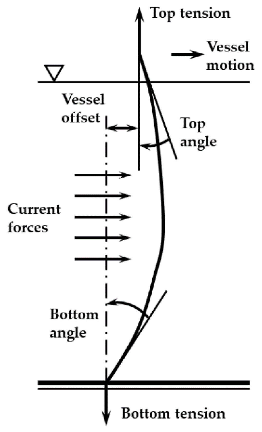
The specific ocean environment load parameters are as follows: the average surface current velocity after regression is VC = 1 m/s, and it is assumed that the current velocity at the middle layer is 75% of the surface current velocity, the current velocity on the seabed is 15% of the surface current velocity, and the current direction is 30°. The profile of the current in the water depth direction is shown in Figure 2. The significant wave height is 7 m, the peak period is 14 s, and the direction is 20°. The average wind speed is 15 m/s and the wind direction is 20°.
Just as shown in Figure 3, The angle of the riser changes as the offset of the offshore platform changes. The appropriate riser angle and platform offset curves produced from the theory in this study and those obtained from the theory in Leira et al. [52] are compared.
The curves in Figure 4a,b demonstrate that, within the acceptable range of errors, the general trend of curve changes and the overall shape distribution are substantially coincident with the results of the work by Leira et al. [52], with minimal variation in values. This demonstrates the feasibility of the theory and approach suggested in this work. The trajectory curve of the Tai’an Kou semi-submersible vessel in the X direction is compared with that of the Tai’an Kou semi-submersible vessel in the X direction with the traditional Kalman filter mode in Dr. Liu’s paper to compare the effect of the unscented Kalman filter and traditional Kalman filter, with reference to the specific parameters of the Tai’an Kou semi-submersible vessel in the Ph.D. thesis of Liu [53]. The dimensionless hydrodynamic coefficient, the inertial mass matrix, and the damping matrix of the semi-submersible vessel are all introduced in detail in Dr. Liu’s thesis, along with the displacement and other pertinent characteristics of the Tai’an Kou semi-submersible vessel. In the simulation process, the force and torque input by the ship’s dynamic positioning system change with time, just as shown in Equation (57):
τ = [ 9000 | sin ( 0.03   t ) | 7500 | sin ( 0.03   t ) | 4500 | sin ( 0.03   t ) | ]
The motion trajectory curve of the Tai’an Kou semi-submersible vessel in the X direction in the unscented Kalman filter mode and the motion trajectory curve in the X direction in the traditional Kalman filter mode in Dr. Liu’s thesis are compared.
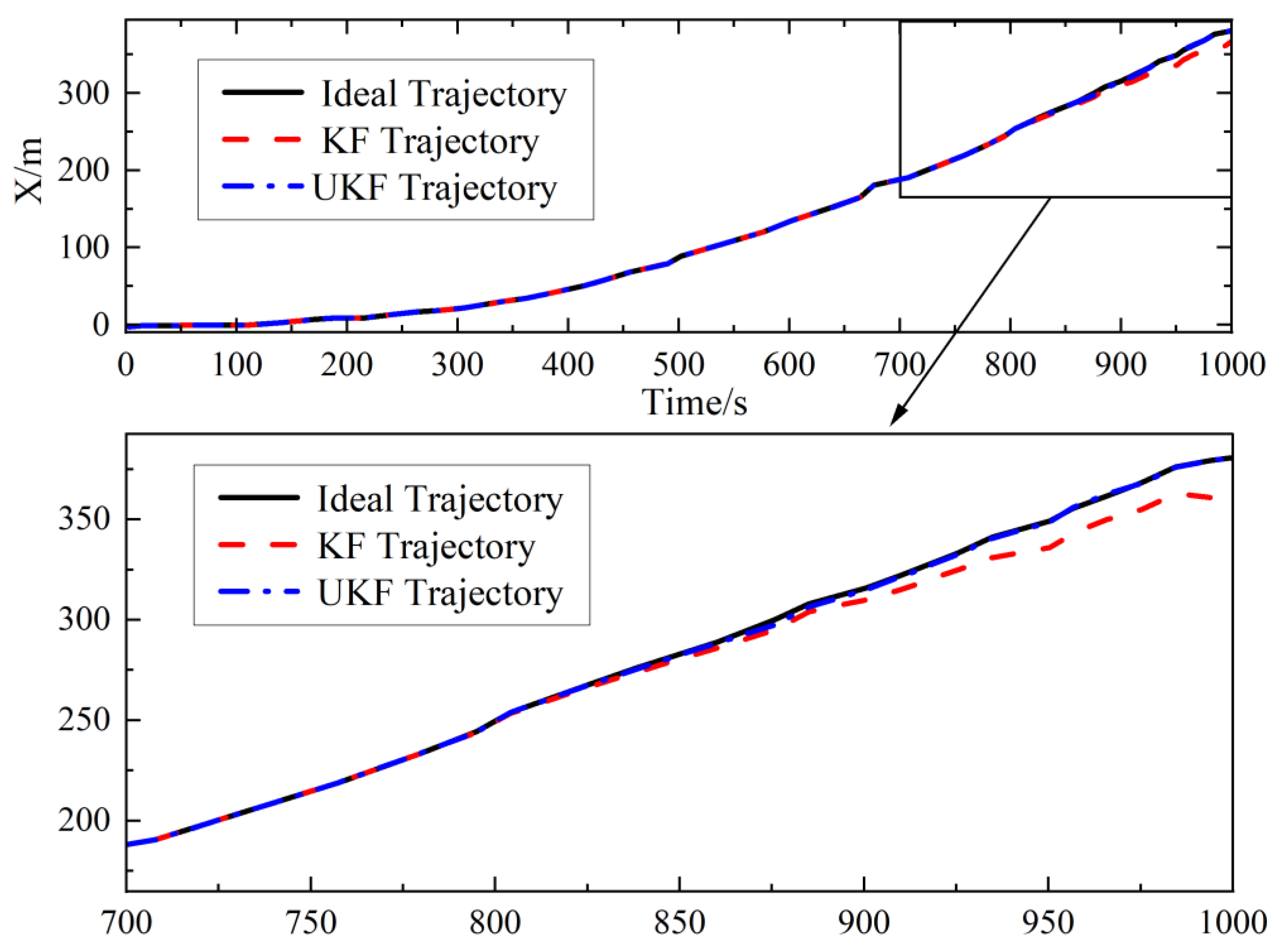
The trajectories of the vessel in the X direction under the two filtering modes (conventional Kalman filter and unscented Kalman filter) are practically identical at the beginning stage of the simulation, as shown in Figure 5. With the extension of time, the ship trajectory in UKF mode is closer to the ideal trajectory, and the trajectory curves in the two filtering modes begin to have obvious differences at 800 s. This difference shows a trend of further expansion with the increase in time. After more than 800 s, the traditional Kalman filter has a divergent tendency as time goes on. Therefore, the trajectory of the vessel with unscented Kalman filter mode in the X direction is closer to the ideal trajectory. The ship trajectory in UKF mode approaches the optimum trajectory as time passes, and the trajectory curves in the two filtering modes begin to diverge at 800 s. This disparity demonstrates a pattern of increasing enlargement as time passes. The standard Kalman filter has a diverging tendency after more than 800 s. As a result, the overall trajectory of the ship using the unscented Kalman filter mode in the X direction is more similar to the ideal trajectory. The dynamic response speed of this method is relatively fast based on the time-domain fluctuation of the vessel’s translation curve in the X direction, and the fast-positioning dynamic response speed means that the time required for the control process will be relatively shortened, which has some reference significance and practical value for practical engineering, and it can also improve the safety margin in practical engineering to some extent. At the same time, it has the potential to increase the economic advantages of offshore positioning operations.
To demonstrate the advantages of the unscented Kalman filter, it must be compared to the extended Kalman filter mode. Unfortunately, most of the parameters presented in the literature on the use of EKF in ship dynamic positioning systems that can currently be discovered are inadequate; therefore, the model reduction comparison analysis cannot be performed in the same way as the standard Kalman filter can. However, with further research and effort, a more idealistic approach of contrasting the extended Kalman filtering mode with the unscented Kalman filtering mode was discovered in Bao’s master’s dissertation [54]. In this case, the approach described by Bao was immediately used, and the trajectory data of the two filtering modes generated by Bao were collected again, analyzed, and compared. The impacts of the two filtering mechanisms were analyzed and compared in this indirect manner. To acquire the filtering effect, Bao simulated the state space equation of the generic nonlinear system, which is represented by the following formula:
{ X ( k + 1 ) = A X ( k ) + B U ( k ) Z ( k ) = H X ( k )
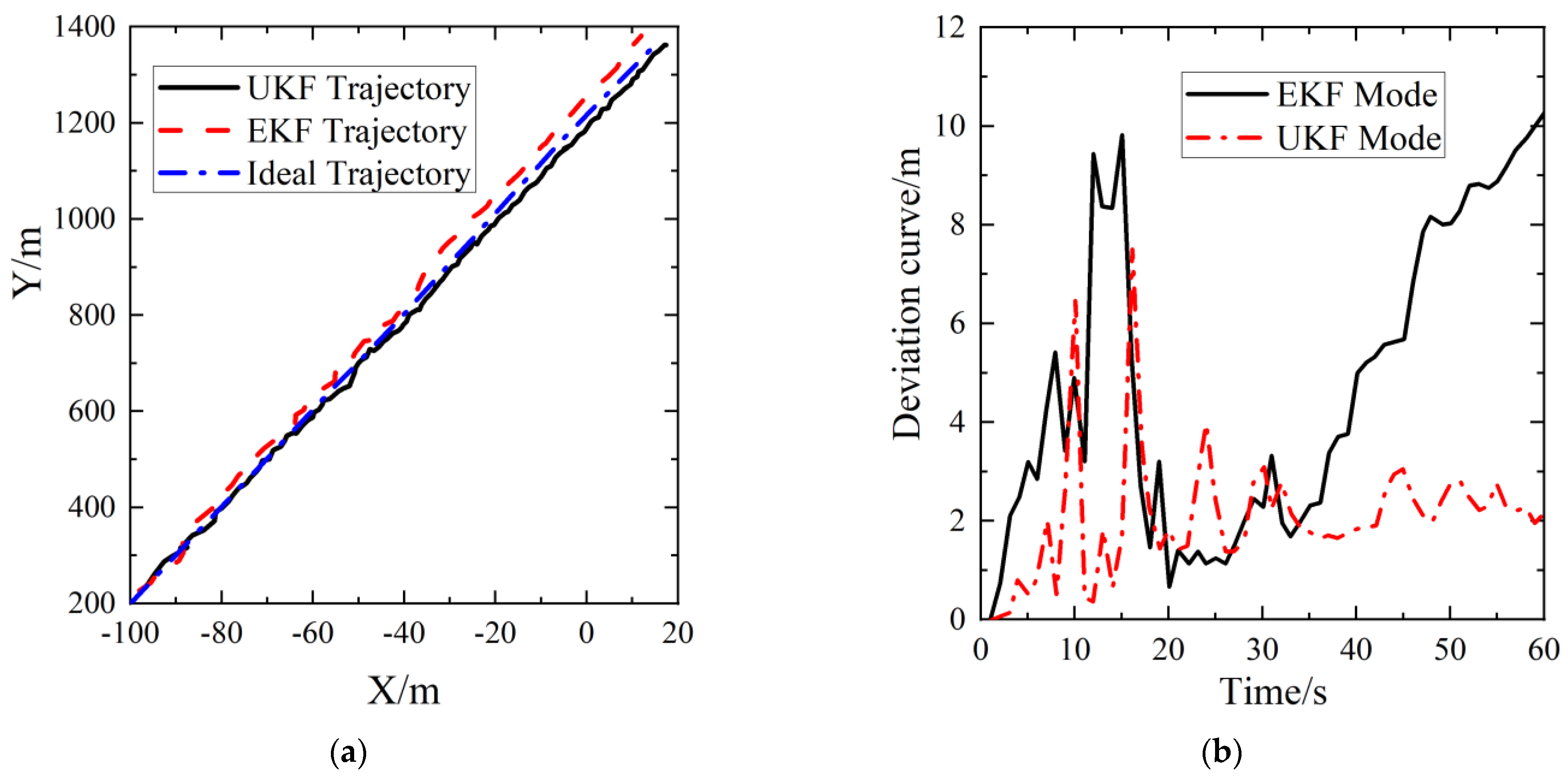
To evaluate the effect, Bao [54] assumes that the variance between the observation noise and the process noise of the preceding nonlinear process is 5 and that the noise is created at random. In Figure 6, it is found that the error correction effect in unscented Kalman filter mode is superior to that in extended Kalman filter mode. The trajectory in the unscented Kalman filter mode is closer to the ideal trajectory in the whole-time domain. This is demonstrated by the fact that the position estimate deviation with unscented Kalman filter mode is less than that with extended Kalman filter mode at any moment in the whole-time domain. Although the deviation of the trajectory in both filtering modes increases at the start of the simulation, the divergence of the trajectory in the unscented Kalman filter mode decreases fast and becomes stable, and the filtering becomes stable. However, the extended Kalman filter mode’s trajectory deviation will develop swiftly and continually, and the extended Kalman filter has a diverging tendency.
When the trajectory deviation is steady in the time domain, the unscented Kalman filter may minimize the trajectory deviation by 80% when compared to the extended Kalman filter mode, and the correction impact will steadily rise with time. Even at the start of the simulation, when the divergence in both filtering modes is large, the unscented Kalman filter may reduce the trajectory deviation by 25%. To summarize, because the dynamic positioning process of ships and offshore platforms is non-linear, the classic Kalman filter and extended Kalman filter ignore high-order elements while linearizing the non-linear process, resulting in varying degrees of model mismatch. The unscented Kalman filter is more insensitive to noise items than the traditional Kalman filter and extended Kalman filter, and UT transformation skips the phase of system linearization, reducing the possibility of model mismatch problems during linearization, so its advantage is more obvious when dealing with non-linear problems.
The above DP platform-riser system considered neither the coupling effects of riser and platform motion nor the effects of waves. Therefore, the above verification has some limitations, and it is impossible to determine the applicability of the coupling theory proposed in this paper in the presence of waves. For this reason, the establishment of the platform-riser multi-body coupling theory based on the lumped mass method proposed in this paper is compared with the same coupling model of the offshore platform riser multi-body system based on the SESAM software proposed by Gu et al. [55]. Because they have compared the calculation results with the model test results in the wind-wave tank, the correctness of the calculation results of the same coupling model of the offshore platform riser multi-body system proposed by them based on the SESAM software has been verified. Therefore, if the calculation results of the verification model are compared with the results of the same coupling model of the platform-riser multi-body system proposed by them based on the SESAM software, the correctness of the theory proposed in this paper can be further verified under wave load.
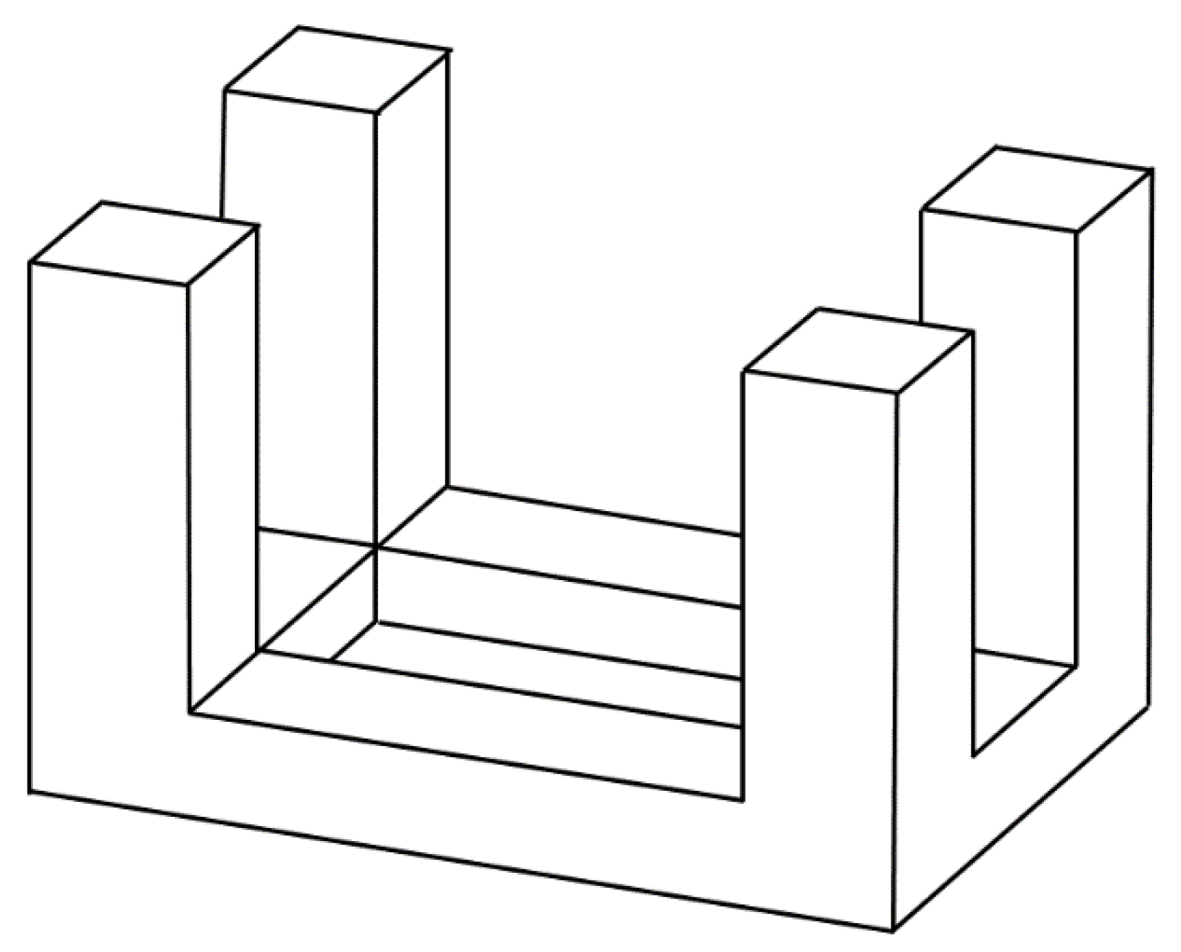
The quadrilateral tension leg platform is shown in Figure 7. The platform consists of four square buoys and four square pontoons. The specific parameters of the offshore platform-riser system are as follows. The design draft is 25.25 m, the diameter of the buoy is 17.4 m, and the center distance of the pontoons is 51.4 m. The length, width, and height of the pontoon are 34 m, 11.6 m, and 8.7 m, respectively. The displacement is 45536 t. In order to be completely consistent with the parameter settings in [55], when the heave, sway, and roll are verified, the wave height is set as 8 m and the wave period is set as 10 s. When the tension is verified, the wave height is set as 12 m and the wave period is 10 s. The water depth is 550 m. Since the RAO of a 270° wave direction is clearly given in [55], the wave direction is set as 270°. However, it should be noted that although the RAO in [55] is given when the wave direction is 270°, the authors did not give the all calculation results when the wave direction is 270°. After further careful review, we found that the calculation results in the original literature were relatively complete when the wave direction was 90°. Since the platform is a quadrilateral platform that is completely symmetrical on the left, right, front, and back, and the layout of risers and tension legs is also completely symmetrical on the left, right, and front, the mechanical parameters of the four risers are identical, and the mechanical parameters of eight tension legs are also identical. The difference between a 90° wave direction and a 270° wave direction is 180°, which is on the same straight line but in opposite directions. Therefore, the cases of 90° wave direction and 270° wave direction are completely symmetrical for the hydrodynamic characteristics of the system. Therefore, the calculation results in these two cases have symmetry.
The validation results are shown in Figure 8. The time-domain curve of heave under the 270° wave direction of the simulation comparison model coincides with that of the 90° wave direction of [55], and its heave amplitude increases by 4% compared with reference [55]. The time-domain curve of sway under the 270° wave direction in the simulation is basically the same as the value on the time-domain curve of sway in the 90° wave direction in [55], and the direction is opposite (the absolute value difference of the down sway value of the two kinds of waves is less than 3%, and the absolute value of the simulated sway is larger). The time-domain curve of roll under the 270° wave is basically the same as the value on the roll time-domain curve of the platform in the 90° wave direction in [55], and the direction is opposite (the difference of the roll value in the two kinds of waves is less than 5%, and the value of the roll is larger). The time-domain curve of tension under the 270° wave direction in the simulation is basically the same as that under the 90° wave direction in [55], and the tension value simulated at each time step is about 7–9% larger than that in the reference [55].
The reason why the tension of the riser in the simulation model is slightly larger at this time is that because the amplitude of the heave, sway, and roll of the platform in the simulation comparison model is slightly increased, the increase in these three motion amplitudes of the platform will lead to the enhancement of the pulling effect on the riser, so the amplitude error of the riser tension compared with the tension value in the literature is slightly larger than the amplitude error of the platform motion. However, the small increase in the platform motion amplitude should be caused by the error that may occur when the RAO data are obtained by point sampling and regression according to the RAO curve, which makes the RAO values increase by a very small margin. In addition, because the method for risers in this paper is discretized into a lumped mass model, compared with the method for risers by Gu et al. [55], this discrete method for risers can better reflect the flexibility of offshore pipelines and make its dynamic response more obvious when the top of the riser moves.

4. Results and Discussion

4.1. Model Establishment

The total length of the riser is 531 m and is discretized by the lumped mass method. The stress-sensitive zone near the upper end of the riser is subdivided. The 0–51 m area is discretized into several special segments: the top 11 m of the riser connected to the offshore platform is lumped into a slip joint; the middle 40 m of the riser is divided into 20 segment units, 2 m for each segment unit; and the bottom 480 m of the riser is discretized into 96 segments with 5 m segmentation units. Except for the top 11 m, the rest of the 520 m is the main part of the riser.
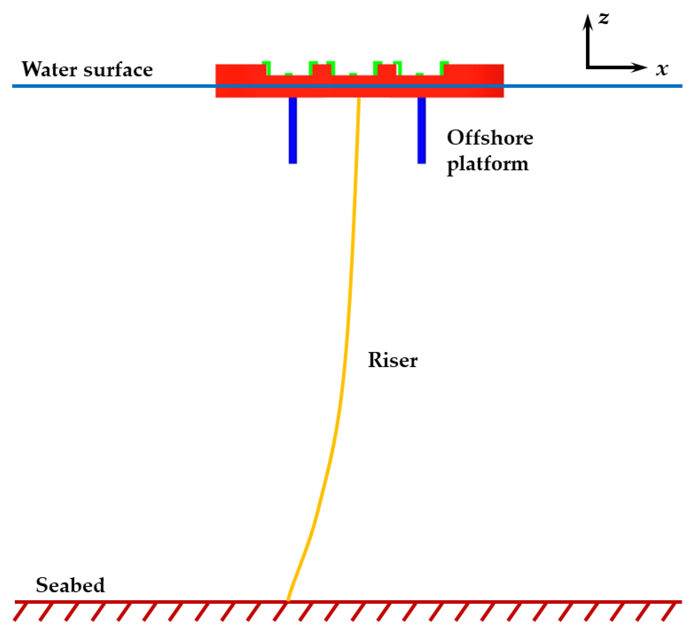
One of the primary characteristics of the riser is that the top tension is reasonably steady, and the effective tension at the bottom end must be positive. As a result, four link elements in the standard cruciform configuration are utilized to adjust and buffer the tension at 11 m from the riser where the top end is positioned, allowing the fluctuation amplitude of the top tension to be within a defined range. The parameters of the main part of the riser are as follows: the outer diameter is 0.65 m, the inner diameter is 0.6 m, Poisson’s ratio is 0.3, Young’s modulus is 21,200 MPa, and the density is 7.85 t/m3. The parameters of the slip joint are as follows: the outer diameter is 0.65 m, the inner diameter is 0.6 m, the bending stiffness is 508,944 kN·m2, the axial stiffness is 1 kN, Poisson’s ratio is 0.3, the torsional stiffness is 391,500 kN·m2, and the linear density is 0.385 t/m. The environmental parameters are as follows: the seawater density is 1025 kg/m3; the water depth is 500 m; the seabed is flat; the JONSWAP spectrum is chosen for the modeling; the peak enhancement factor γ is 4.7934; a is 0.0086, which is calculated by the specified Hs and Tz; σ1 is 0.07 and σ2 is 0.09; the significant wave height Hs is 7 m; the zero crossing period Tz is 9 s; the wave direction is 270°; the current is 0.5 m/s; and the direction of the current is the same as the wave direction. The offshore platform has eight pontoons, the draught of the offshore platform is 24.38 m, the displacement is 10,000 t, and the moments of inertia are Ix = 500,000 t.m2, Iy = 7,000,000 t.m2, Iz = 7,000,000 t.m2, respectively. The positioning coordinates of the offshore platform are (target X = +30 m, target Y = −20 m), target heading = 90°. The schematic diagram of the model is shown in Figure 9.
The UKF-PID control of the offshore platform motion in the system is realized by combining the OrcaFlex API with a PID dynamic positioning control statement in UKF mode based on Python programming.

4.2. Calculation Analysis

4.2.1. Effective Tension of Riser under the UKF-PID and Single PID

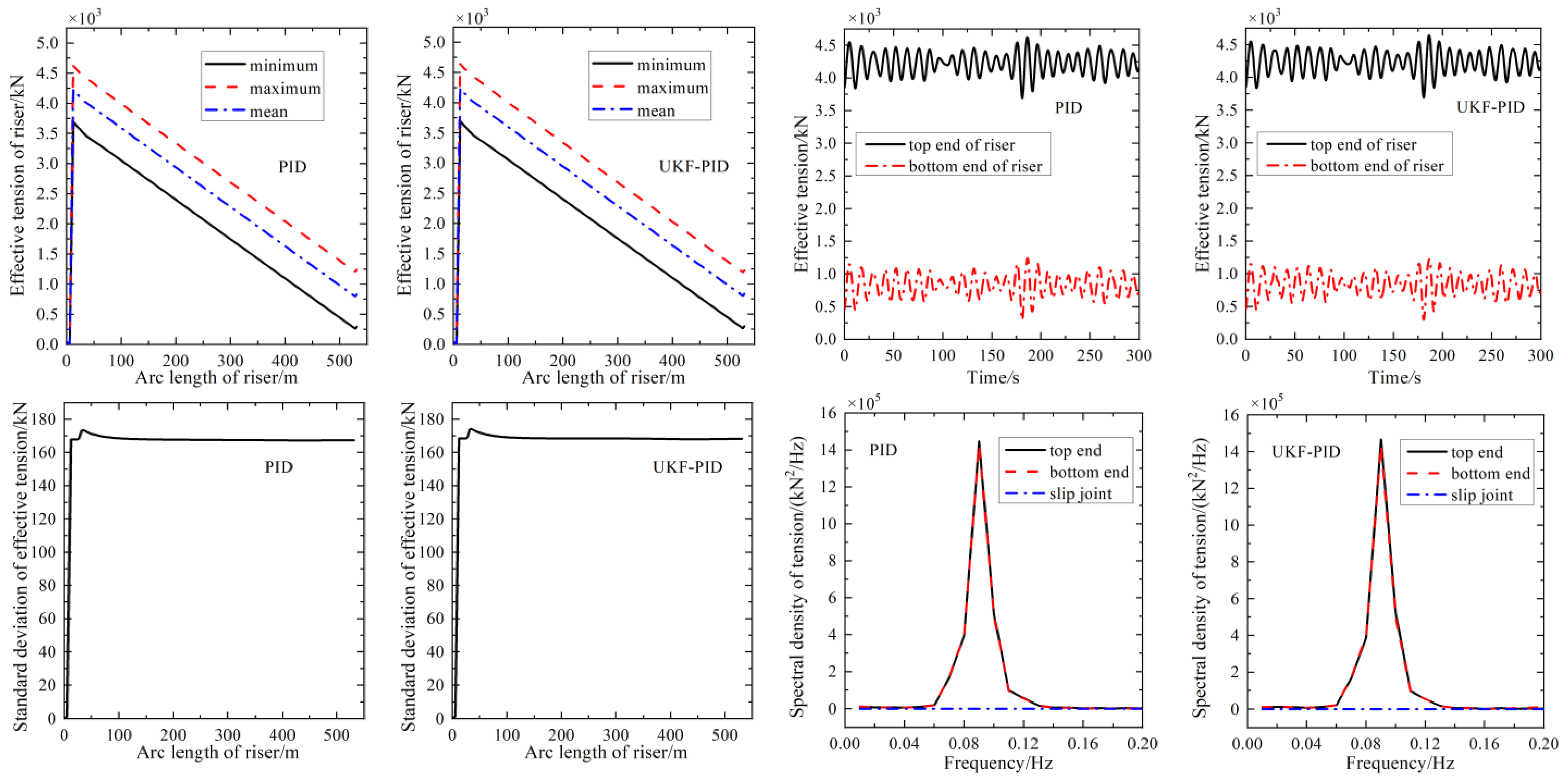
Figure 10 depicts the distributions of effective tension in the length direction of the riser under the action of the UKF-PID (PID control with unscented Kalman filter) dynamic positioning system and single PID dynamic positioning system. It is found that the curve configurations and values of the effective tension of the riser under PID control in unscented Kalman filter mode in the length direction have little difference, which means that the effective tension of the riser does not change much in the length direction in this mode. The presence of an unscented Kalman filter has no effect on the distribution of the effective tension of the riser in the length direction, and its influence on the change of tension at a specific position on the riser is quite weak. The curves of the effective tension spectral density at the three ends of the riser and the standard deviation distribution of the effective tension in the length direction are also very similar to the corresponding riser curves in the dynamic positioning offshore platform-riser multi-body system under a single PID control. This demonstrates that the inclusion of an unscented Kalman filter has no effect on the magnitude of riser tension, time-domain fluctuation, distribution of riser tension throughout the length of the riser, coordination, and synchronism of riser tension variation. In other words, the inclusion of the unscented Kalman filter has less of an impact on the riser’s tension variation than the multi-body offshore platform riser controlled by a single PID, which is completely represented in the riser’s fluctuation, coordination, and synchronization of tension variation.

4.2.2. Bending Moment and Curvature of Riser under UKF-PID and Single PID

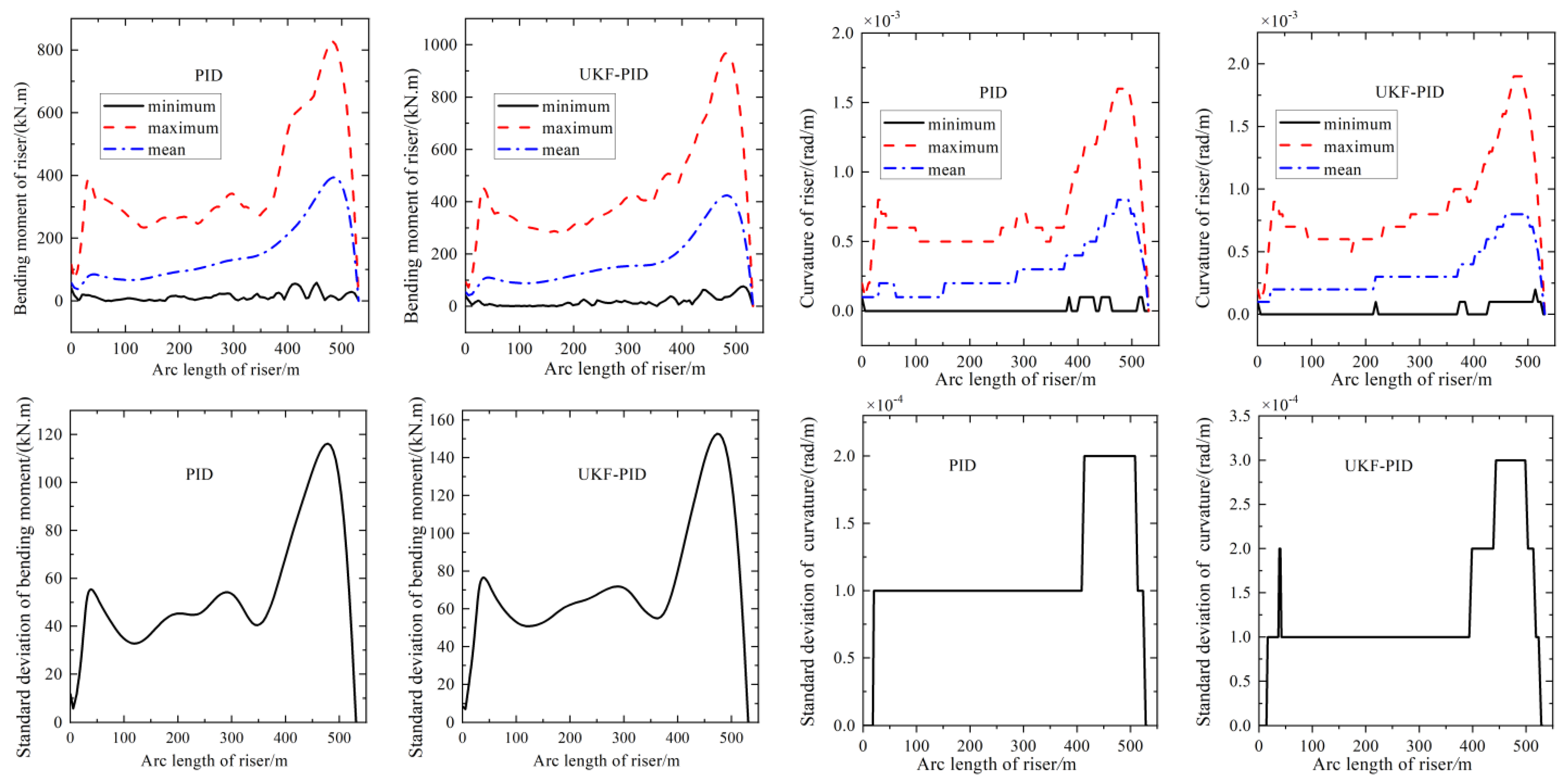
Figure 11 depicts the curves of the distributions of the bending moment and curvature in the length direction of the riser under the action of the UKF-PID dynamic positioning system and single PID dynamic positioning system. It is discovered that the bending moment of the riser under the UKF-PID dynamic positioning system is greater than the position under a single PID control at a certain position in the length direction, but the position where the riser is subjected to greater bending does not change in the whole length direction, implying that the bending moment of the riser increases greatly in the whole-length direction with the addition of the unscented Kalman filter but does not change the position. It can be seen from the variation of the effective tension of the riser under the action of the UKF-PID dynamic positioning system that the existence of the UKF-PID dynamic positioning system does not change the distribution and variation of the axial tension of the riser, but changes the distribution and variation of the lateral bending load of the riser. The standard deviations of the riser curvature under the influence of the UKF-PID dynamic positioning system not only increase throughout the entire-length direction but also the distributions of the curvature standard deviation curves in the length direction of the riser have changed significantly. The curvature standard deviation curves exhibit stronger stepped distributive behavior compared with the corresponding calculation results of the multi-body system under a single PID control. This demonstrates how the addition of the unscented Kalman filter increases the non-coordination of the riser’s curvature fluctuation over the full-length direction and its non-linearity.
The non-synchronization and non-coordination of the variation of the curvature of the riser, as well as the stepped distribution in the length direction, are increasingly apparent as the standard deviation of the curvature of the riser’s standard deviation increases. This indicates that when the unscented Kalman is included, the riser’s synchronization of the curvature variation of the riser diminishes in the whole-length direction and tends to have a stronger and more discrete stepped distribution. As a result, the strong nonlinearity of the riser’s bending is better reflected with the addition of the unscented Kalman filter, which is beneficial for the visual capture of the nonlinear characteristics in the engineering practice, the investigation of potential safety hazards, and the adoption of pertinent measures to improve security.

4.2.3. Rotation Angle of Riser under the Action of UKF-PID and Single PID

The distribution of the Rx, Ry, and Rz angles in the length direction of the riser under the action of the UKF-ID dynamic positioning system is found to be larger than those at the same position of the riser of the offshore platform-riser system under the control mode of the single PID dynamic positioning system, but the distribution of Rx angles in the length direction of the riser has no significant change. This implies that, with the addition of the unscented Kalman filter, the filtering effect enhances the motion component of the offshore platform in a specific direction, resulting in the nonlinear bending of the riser in a specific direction, which makes the riser endure bending and strengthens the bending around its own local coordinate system in the y-axis direction, and the degree of the bending around the x-axis has increased.
Figure 12 depicts the rotation angle in the length direction of the riser under the action of the UKF-PID dynamic positioning system and single PID dynamic positioning system. The torsional impact of the riser along its own axial axis z is nevertheless magnified when compared to the calculation results under the single PID control condition, but the Rz angles induced by this action are still small when compared to Rx and Ry. This behavior is caused by the insertion of an unscented Kalman filter, which nonlinearly enhances the whole motion of the offshore platform-riser rigid flexible system. The nonlinear amplification of the entire system motion increases the motion response to change more quickly when the system overcomes a change in the external environment load, which also boosts the riser’s bending and twisting. The variation of the Ry angle dramatically increases with the addition of the unscented Kalman filter, but the synchronization and coordination of the variation of the Ry angle in the length direction of the riser basically halve when the distributions of the standard deviations of the Ry angle of the riser under the action of UKF-PID dynamic positioning system and those under the action of a single PID dynamic positioning system are compared.
The synchronization and coordination of the variation of the riser’s Rz angle under the action of the single PID dynamic positioning system have a stepped distribution and abrupt change in the length direction when comparing the distributions of the standard deviations of the Ry angle of the riser under the action of UKF-PID dynamic positioning system to those under the action of the single PID dynamic positioning system. However, the coordination and synchronization of the variation of the Rz angle of the riser under the action of the UKF-PID dynamic positioning system does not change abruptly in the length direction of the riser, but rather slowly. This indicates that the addition of an unscented Kalman filter increases the flexibility of the entire system by synchronizing and coordinating the variation of the Rz angle in a manner that is orderly and gradually decreases and grows in the length direction. The Rx, Ry, and Rz angles and their related standard deviations under the control of the UKF-PID dynamic positioning system do not vary appreciably as the velocity of the content flow increases.

4.2.4. Six Degrees of Freedom of the Offshore Platform under the Action of UKF-PID and Single PID

The three-degrees-of-freedom translational motion of the offshore platform under the action of the UKF-PID dynamic positioning system has been observed using time-domain curves, and it is discovered that this motion is altered significantly when compared to that under the action of the single PID dynamic positioning system. The maximum sway amplitude is significantly lowered before the sway motion achieves a steady state, and the time needed to reach the steady state of its sway motion is further shortened, but the fluctuation in the surge direction somewhat rises. When compared to the single PID dynamic positioning system, there is not much of a difference in the time-domain response in the sway direction. When compared to a single PID dynamic positioning system, the main change in the time-domain curves of the three-degrees-of-freedom rotational motion of the offshore platform under the action of the UKF-PID dynamic positioning system is reflected in the change of the yaw angle, in which case, the yaw angle of the offshore platform has a small sustained fluctuation in the subsequent time step with a short stagnation at the initial time step in the time domain. The cause of this phenomenon is likewise connected to the system’s overall nonlinear increase with the inclusion of the unscented Kalman filter.
Figure 13 depicts the six degrees of freedom of the offshore platform under the action of the UKF-PID dynamic positioning system and single PID dynamic positioning system. The direction of the surge motion is where the offshore platform’s translational motion spectral density changes the most. The offshore platform surge motion spectral density in the single PID dynamic positioning system contains two low peaks, one of which is lower than the peak frequency of the heave motion spectral density, and the other of which is higher than the peak frequency of the heave motion spectral density. However, the surge motion spectral density of the offshore platform has just one high peak value under the action of the UKF-PID dynamic positioning system, and its corresponding frequency is larger than that of the heave motion spectral density. In other words, the superharmonic resonance of the offshore platform in the direction of the surge motion vanishes under the influence of the UKF-PID dynamic positioning system, which helps to boost the safety of the entire offshore platform-riser rigid–flexible system and reduces the risk of fatigue damage. The three-degrees-of-freedom rotational motion spectral density curves of the offshore platform under the action of UKF-PID dynamic positioning are essentially the same as those of the offshore platform under the action of single PID dynamic positioning.

5. Conclusions

In this paper, a new PID control approach based on the unscented Kalman filter for the dynamic positioning offshore platform-riser multi-body system is created by merging the unscented Kalman filter with the traditional PID control. The DP control of a rigid–flexible fluid coupling system composed of an offshore platform and risers is realized. Compared with the traditional PID control, the calculation results of UKF-PID control demonstrate the following:
(1)
The effect of the UKF-PID dynamic positioning system on the variation of the effective tension of the riser is not significant, which is fully reflected in the fluctuation, coordination, and synchronism of the variation. Compared with the multi-body system controlled by a single PID static positioning system, the bending moment of the platform riser becomes larger when the positioning system is changed. With the addition of the unscented Kalman filter, the strong nonlinearity of riser bending change in the whole system is better reflected. This is helpful for the visual capture of this nonlinearity in engineering practice and the investigation of potential safety hazards and measures to improve safety.
(2)
Compared with the dynamic positioning system under the control of a single PID, the bending moment of the riser in the UKF-PID dynamic positioning system and the transmission of bending along the length of the riser will change. This change is mainly reflected in a relatively larger bending moment. The bending moment of the riser at a certain position will be more severe, but the relative hysteresis of the bending moment and curvature still exists. In addition, the hysteresis of load and strain transfer will be further enhanced at some locations. In this case, the overall synchronization and coordination of riser curvature changes along the length direction will be reduced.
(3)
The proposed control approach of this paper improves the nonlinearity of the three-degrees-of-freedom translational movements of the offshore platform and modifies the energy distribution in three translation motions of the offshore platform. Under UKF-PID control, the overall motion nonlinearity of the offshore platform-riser multi-body system has been significantly improved. The enhancement of nonlinearity makes the system more sensitive to the change of its own motion response when overcoming the change of external environmental load, which also leads to the increase in the Ry and Rz angles of the riser.
Due to the complexity limit of the rigid–flexible multi-body system, the forces and moments of the DP offshore platform under external environmental loads are exerted on the center of mass of the offshore platform to achieve its positioning control. This method is feasible when considering the interaction between the riser and DP offshore platform in the overall analysis and can greatly improve the calculation efficiency. However, in practical engineering, the dynamic positioning of offshore platforms is achieved by arranging different thrusters at different coordinate positions and then providing different thrusts and torques or changing the direction of thrusts and moments by adjusting the speed and spatial azimuth of the thruster. Therefore, the research in this paper is still simplified. Future work will focus on how to add the component force and spatial azimuth provided by each thruster to the dynamic model to better conform to the real engineering situation.

Author Contributions

Conceptualization, D.Z. and B.Z.; methodology, D.Z. and Y.B.; software, K.Z.; validation, D.Z. and K.Z.; formal analysis, D.Z. and B.Z.; investigation, K.Z. and B.Z.; resources, D.Z.; data curation, K.Z.; writing—original draft preparation, D.Z.; writing—review and editing, D.Z.; visualization, K.Z.; supervision, D.Z. and Y.B.; funding acquisition, D.Z. All authors have read and agreed to the published version of the manuscript.

Funding

This research was funded by the Program for Scientific Research Start-up Funds of Guangdong Ocean University, grant number 060302072101, and Zhanjiang Marine Youth Talent Project-Comparative Study and Optimization of Horizontal Lifting of Subsea Pipeline, grant number 2021E5011.

Institutional Review Board Statement

Not applicable.

Informed Consent Statement

Not applicable.

Data Availability Statement

Not applicable.

Conflicts of Interest

The authors declare no conflict of interest.

References

  1. Altuzarra, J.; Herrera, A.; Matías, O.; Urbano, J.; Romero, C.; Wang, S.; Guedes Soares, C. Mooring System Transport and Installation Logistics for a Floating Offshore Wind Farm in Lannion, France. J. Mar. Sci. Eng. 2022, 10, 1354. [Google Scholar] [CrossRef]
  2. Amaechi, C.V.; Reda, A.; Butler, H.O.; Ja’E, I.A.; An, C. Review on fixed and floating offshore structures. Part I: Types of platforms with some applications. J. Mar. Sci. Eng. 2022, 10, 1074. [Google Scholar] [CrossRef]
  3. Amaechi, C.V.; Reda, A.; Butler, H.O.; Ja’E, I.A.; An, C. Review on fixed and floating offshore structures. Part II: Sustainable design approaches and project management. J. Mar. Sci. Eng. 2022, 10, 973. [Google Scholar] [CrossRef]
  4. Li, C.B.; Chen, M.; Choung, J. The Quasi-Static Response of Moored Floating Structures Based on Minimization of Mechanical Energy. J. Mar. Sci. Eng. 2021, 9, 960. [Google Scholar] [CrossRef]
  5. Chen, C.; Shiotani, S.; Sasa, K. Numerical ship navigation based on weather and ocean simulation. Ocean Eng. 2013, 69, 44–53. [Google Scholar] [CrossRef] [Green Version]
  6. Nguyen, V.S. A novel approach to determine the ship position with an azimuth of celestial body and factors of ship route. Int. J. Civil. Eng. Technol. 2019, 10, 1162–1167. [Google Scholar]
  7. Lee, D.; Lee, S.J. Motion predictive control for DPS using predicted drifted ship position based on deep learning and replay buffer. Int. J. Nav. Arch. Ocean 2020, 12, 768–783. [Google Scholar] [CrossRef]
  8. Cheng, Z.; Gao, Z.; Moan, T. Numerical modeling and dynamic analysis of a floating bridge subjected to wind, wave, and current loads. J. Offshore Mech. Arct. Eng. 2019, 141, 011601. [Google Scholar] [CrossRef]
  9. Nagavinothini, R.; Chandrasekaran, S. Dynamic analyses of offshore triceratops in ultra-deep waters under wind, wave, and current. Structures 2019, 20, 279–289. [Google Scholar] [CrossRef]
  10. Zhang, D.; Bai, Y.; Soares, C.G. Dynamic analysis of an array of semi-rigid “sea station” fish cages subjected to waves. Aquac. Eng. 2021, 94, 102172. [Google Scholar] [CrossRef]
  11. Loria, A.; Fossen, T.I.; Panteley, E. A separation principle for dynamic positioning of ships: Theoretical and experimental results. IEEE Trans. Control Syst. Technol. 2000, 8, 332–343. [Google Scholar] [CrossRef]
  12. Dutopo, H.; Marwanto, A.; Alifah, S.; Hidayah, M. Improved ship position stability on offshore-based dynamic position maintenance with the PID method. Tech. Rom. J. Appl. Sci. Technol. 2022, 4, 99–112. [Google Scholar] [CrossRef]
  13. Hao, L.; Zhang, H.; Li, T.; Lin, B.; Chen, C.P. Fault tolerant control for dynamic positioning of unmanned marine vehicles based on TS fuzzy model with unknown membership functions. IEEE Trans. Veh. Technol. 2021, 70, 146–157. [Google Scholar] [CrossRef]
  14. Deng, F.; Yang, H.; Wang, L. Adaptive unscented Kalman filter based estimation and filtering for dynamic positioning with model uncertainties. Int. J. Control. Autom. Syst. 2019, 17, 667–678. [Google Scholar] [CrossRef]
  15. Liu, L.; Zhang, W.; Wang, D.; Peng, Z. Event-triggered extended state observers design for dynamic positioning vessels subject to unknown sea loads. Ocean Eng. 2020, 209, 107242. [Google Scholar] [CrossRef]
  16. Witkowska, A.; Śmierzchalski, R. Adaptive dynamic control allocation for dynamic positioning of marine vessel based on backstepping method and sequential quadratic programming. Ocean Eng. 2018, 163, 570–582. [Google Scholar] [CrossRef]
  17. Pettersen, K.Y.; Fossen, T.I. Under actuated dynamic positioning of a ship-experimental results. IEEE Trans. Control Syst. Technol. 2000, 8, 856–863. [Google Scholar] [CrossRef] [Green Version]
  18. Fossen, T.I. Guidance and Control of Ocean Vehicles. Doctors Thesis, University of Trondheim, Trondheim, Norway, 1994. [Google Scholar]
  19. Fossen, T.I.; Grovlen, A. Nonlinear output feedback control of dynamically positioned ships using vectorial observer backstepping. IEEE Trans. Control Syst. Technol. 1998, 6, 121–128. [Google Scholar] [CrossRef]
  20. Skjetne, R.; Fossen, T.I.; Petar, V. Kokotović. Adaptive maneuvering, with experiments, for a model ship in a marine control laboratory. Automatica 2005, 41, 289–298. [Google Scholar] [CrossRef]
  21. Morawski, L.; Nguyen, C.V. Ship control in maneuvering situation with fuzzy logic controllers. TransNav Int. J. Mar. Navig. Saf. Od Sea Transp. 2008, 2, 77–84. [Google Scholar]
  22. Lee, G.; Surendran, S.; Kim, S.H. Algorithms to control the moving ship during harbour entry. Appl. Math. Model. 2009, 33, 2474–2490. [Google Scholar] [CrossRef]
  23. Bui, V.P.; Kawai, H.; Kim, Y.B.; Lee, K.S. A ship berthing system design with four tug boats. J. Mech. Sci. Technol. 2011, 25, 1257–1264. [Google Scholar] [CrossRef]
  24. Fossen, T.I.; Strand, J.P. Passive nonlinear observer design for ships using lyapunov methods: Experimental Results with a Supply Vessel. Automatica 1999, 35, 3–16. [Google Scholar] [CrossRef]
  25. Sorensen, A.J.; Strand, J.P.; Fossen, T.I. Thruster assisted position mooring system for turret-anchored FPSOs. In Proceedings of the IEEE International Conference on Control Applications, Kohala Coast, HI, USA, 22–27 August 1999. [Google Scholar]
  26. Wicher, J.; Van, D.R. Benefits of using assisted DP for deepwater mooring systems. In Proceedings of the Offshore Technology Conference, Houston, TX, USA, 3–6 May 1999. [Google Scholar]
  27. Aalbers, A.B.; Merchant, A.A. The hydrodynamic model testing for closed loop DP assisted mooring. In Proceedings of the Offshore Technology Conference, Houston, TX, USA, 3–6 May 1996. [Google Scholar]
  28. Sørheim, H.R. Analysis of motion in single-point mooring systems. Modeling Ident Control 1980, 1, 165–186. [Google Scholar] [CrossRef]
  29. Wichers, J.E. On the slow motions of tankers moored to single point mooring systems. J. Petro. Technol. 1978, 30, 13–33. [Google Scholar] [CrossRef]
  30. Lopez-Cortijo, J.; Duggal, A.S.; Van Dijk, R.R.; Matos, S. DP FPSO-A Fully Dynamically Positioned FPSO For Ultra Deep Waters. In Proceedings of the Thirteenth International Offshore and Polar Engineering Conference, Honolulu, HI, USA, 25 May 2003. [Google Scholar]
  31. Tannuri, E.A.; Saad, A.C.; Morishita, H.M. Offloading operation with a DP shuttle tanker: Comparison between full scale measurements and numerical simulation results. IFAC Proc. Vol. 2009, 42, 249–254. [Google Scholar] [CrossRef]
  32. Ja’E, I.A.; Ali, M.O.A.; Yenduri, A.; Nizamani, Z.; Nakayama, A. Optimisation of mooring line parameters for offshore floating structures: A review paper. Ocean Eng. 2022, 247, 110644. [Google Scholar] [CrossRef]
  33. Yan, J.; Qiao, D.; Li, B.; Wang, B.; Liang, H.; Ning, D.; Ou, J. An improved method of mooring damping estimation considering mooring line segments contribution. Ocean Eng. 2021, 239, 109887. [Google Scholar] [CrossRef]
  34. He, X.; Zhao, Z.; Su, J.; Yang, Q.; Zhu, D. Adaptive inverse control of a vibrating coupled vessel-riser system with input backlash. IEEE Trans Syst. Man Cybern. Syst. 2019, 51, 4706–4715. [Google Scholar] [CrossRef] [Green Version]
  35. Liu, X.; Liu, Z.; Wang, X.; Zhang, N.; Qiu, N.; Chang, Y.; Chen, G. Recoil control of deepwater drilling riser system based on optimal control theory. Ocean Eng. 2021, 220, 108473. [Google Scholar] [CrossRef]
  36. Yu, J.; Wang, F.; Yu, Y.; Liu, X.; Liu, P.; Su, Y. Test System Development and Experimental Study on the Fatigue of a Full-Scale Steel Catenary Riser. J. Mar. Sci. Eng. 2022, 10, 1325. [Google Scholar] [CrossRef]
  37. Aly, A.A.; The Vu, M.; El-Sousy, F.F.; Alotaibi, A.; Mousa, G.; Le, D.; Mobayen, S. Fuzzy-Based Fixed-Time Nonsingular Tracker of Exoskeleton Robots for Disabilities Using Sliding Mode State Observer. Mathematics 2022, 10, 3147. [Google Scholar] [CrossRef]
  38. Vu, M.T.; Choi, H.; Nhat, T.Q.M.; Nguyen, N.D.; Lee, S.; Le, T.; Sur, J. Docking assessment algorithm for autonomous underwater vehicles. Appl. Ocean Res. 2020, 100, 102180. [Google Scholar] [CrossRef]
  39. Vu, M.T.; Choi, H.; Nguyen, N.D.; Kim, S. Analytical design of an underwater construction robot on the slope with an up-cutting mode operation of a cutter bar. Appl. Ocean Res. 2019, 86, 289–309. [Google Scholar] [CrossRef]
  40. Vu, M.T.; Jeong, S.; Choi, H.; Oh, J.; Ji, D. Study on down-cutting ladder trencher of an underwater construction robot for seabed application. Appl. Ocean Res. 2018, 71, 90–104. [Google Scholar] [CrossRef]
  41. Mobayen, S.; Bayat, F.; Din, S.U.; Vu, M.T. Barrier function-based adaptive nonsingular terminal sliding mode control technique for a class of disturbed nonlinear systems. ISA Trans. 2022, 8, 006. [Google Scholar] [CrossRef]
  42. Huang, J.; Choi, H.; Vu, M.T.; Jung, D.; Choo, K.; Cho, H.; Nam Anh, P.H.; Zhang, R.; Park, J.; Kim, J. Study on Position and Shape Effect of the Wings on Motion of Underwater Gliders. J. Mar. Sci. Eng. 2022, 10, 891. [Google Scholar] [CrossRef]
  43. Jin, H.; Cho, H.; Jiafeng, H.; Lee, J.; Kim, M.; Jeong, S.; Ji, D.; Joo, K.; Jung, D.; Choi, H. Hovering control of UUV through underwater object detection based on deep learning. Ocean Eng. 2022, 253, 111321. [Google Scholar] [CrossRef]
  44. Cho, H.; Jeong, S.; Ji, D.; Tran, N.; Vu, M.T.; Choi, H. Study on control system of integrated unmanned surface vehicle and underwater vehicle. Sensors 2020, 20, 2633. [Google Scholar] [CrossRef]
  45. Nguyen, N.; Choi, H.; Lee, S. Robust adaptive heading control for a ray-type hybrid underwater glider with propellers. J. Mar. Sci. Eng. 2019, 7, 363. [Google Scholar] [CrossRef] [Green Version]
  46. Vu, M.T.; Choi, H.; Kim, J.; Tran, N.H. A study on an underwater tracked vehicle with a ladder trencher. Ocean Eng. 2016, 127, 90–102. [Google Scholar] [CrossRef]
  47. Vu, M.T.; Choi, H.; Kang, J.; Ji, D.; Jeong, S. A study on hovering motion of the underwater vehicle with umbilical cable. Ocean Eng. 2017, 135, 137–157. [Google Scholar]
  48. Vu, M.T.; Van, M.; Bui, D.H.P.; Do, Q.T.; Huynh, T.; Lee, S.; Choi, H. Study on dynamic behavior of unmanned surface vehicle-linked unmanned underwater vehicle system for underwater exploration. Sensors 2020, 20, 1329. [Google Scholar] [CrossRef] [PubMed]
  49. Wang, S. On the assessment of thruster assisted mooring. In Proceedings of the Offshore Technology Conference, Houston, TX, USA, 3–6 May 2010. [Google Scholar]
  50. Bai, Y.; Zhang, D.; Zhu, K.; Zhang, T. Dynamic analysis of umbilical cable under interference with riser. Ships Offshore Struct. 2018, 13, 809–821. [Google Scholar] [CrossRef]
  51. Sørensen, A.J.; Leira, B.; Peter, S.J.; Larsen, C.M. Optimal setpoint chasing in dynamic positioning of deep-water drilling and intervention vessels. Rob. Nonlinear Control 2001, 11, 1187–1205. [Google Scholar] [CrossRef]
  52. Leira, B.; Chen, Q.; Sørensen, A.J.; Larsen, C.M. Modeling of riser response for DP control. J. Offshore Mech. Arct. Eng. 2002, 124, 219–225. [Google Scholar] [CrossRef]
  53. Liu, F. Research on Modeling and Simulating of Dynamic Positioning Control System of the Semi-Submersible Vessel; Wuhan University of Technology: Wuhan, China, 2011. (In Chinese) [Google Scholar]
  54. Bao, W. Research on Time Domain Analysis of Dynamic Positioning System for Drilling Platform; Jiangsu University of Science and Technology: Zhenjiang, China, 2018. (In Chinese) [Google Scholar]
  55. Gu, J.; Lu, H.; Yang, J. Studies on coupling dynamic response of TLP in stochastic waves. J. Ship. Mech. 2013, 17, 888–900. (In Chinese) [Google Scholar]
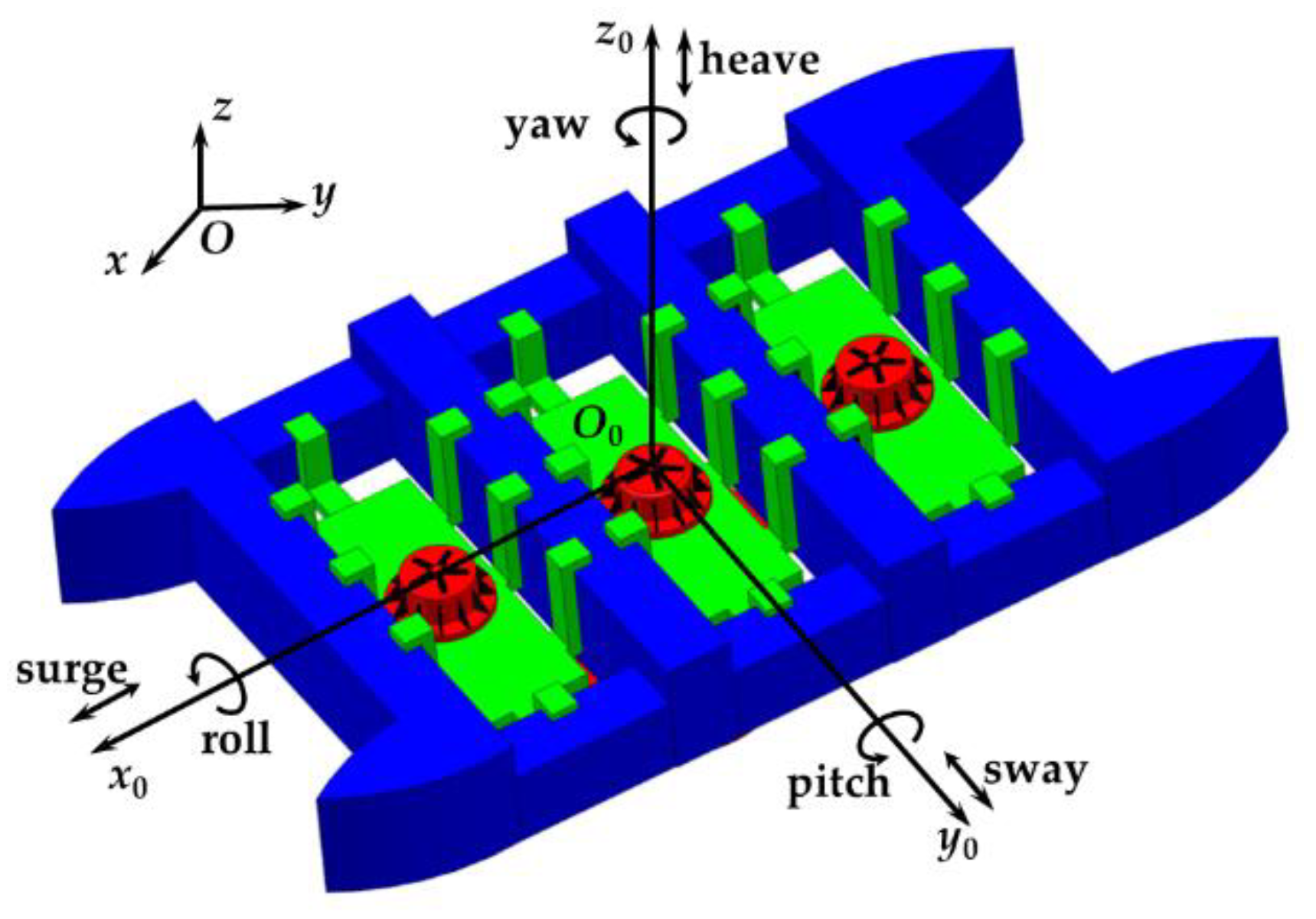
Figure 1. Two coordinate systems.
Jmse 10 01596 g001
Figure 2. View of the current profile.
Jmse 10 01596 g002
Figure 3. Validation model of the riser.
Jmse 10 01596 g003
Figure 4. (a) Top riser angle versus offset of offshore platform. (b) Bottom riser angle versus offset of offshore platform[52].
Jmse 10 01596 g004
Figure 5. Trajectories of “Tai’an Kou” in the time domain with UKF and KF.
Jmse 10 01596 g005
Figure 6. (a) Trajectories with EKF and UKF. (b) Deviation curves with EKF and UKF.
Jmse 10 01596 g006
Figure 7. Validation model of a platform.
Jmse 10 01596 g007
Figure 8. Bending moment and curvature of the riser under the action of UKF-PID and single PID [55].
Jmse 10 01596 g008
Figure 9. Model of the rigid–flexible fluid multi-body system with a dynamic positioning system of UKF-PID.
Jmse 10 01596 g009
Figure 10. Dynamic response of the effective tension of the riser under the action of UKF-PID and single PID.
Jmse 10 01596 g010
Figure 11. Bending moment and curvature of the riser under the action of UKF-PID and single PID.
Jmse 10 01596 g011
Figure 12. Dynamic response of the rotation angle of the riser under the action of UKF-PID and single PID.
Jmse 10 01596 g012
Figure 13. Six degrees of freedom of the offshore platform under UKF-PID and single PID.
Jmse 10 01596 g013aJmse 10 01596 g013b
Publisher’s Note: MDPI stays neutral with regard to jurisdictional claims in published maps and institutional affiliations.