Article

A Study on the Enhanced Process of Elaborate Heat Source Model Parameters for Flux Core Arc Welding of 9% Nickel Steel for Cryogenic Storage Tank

1
Automotive Materials & Components R&D Group, Korea Institute of Industrial Technology, Gwangju 61012, Republic of Korea
2
School of Mechanical Engineering, Gwangju Institute of Science and Technology, Gwangju 61005, Republic of Korea
3
Department of Naval Architecture and Ocean Engineering, Chosun University, Gwangju 61452, Republic of Korea
4
Research Institute of Medium & Small Shipbuilding, Yeongam 58457, Republic of Korea
5
Innovation, Policy and Entrepreneurship Thrust, Hong Kong University of Science and Technology (Guangzhou), Guangzhou 511453, China
6
Department of Naval Architecture and Offshore Engineering, Dong-A University, Busan 49315, Republic of Korea
7
School of Mechanical Engineering, Chonnam National University, Gwangju 61186, Republic of Korea
*
Authors to whom correspondence should be addressed.
These authors contributed equally to this work.
J. Mar. Sci. Eng. 2022, 10(12), 1810; https://doi.org/10.3390/jmse10121810
Submission received: 13 October 2022 / Revised: 12 November 2022 / Accepted: 17 November 2022 / Published: 23 November 2022
(This article belongs to the Special Issue Marine Alternative Fuels and Environmental Protection II)

Abstract

:
Various regulations are being devised and implemented to prevent the environmental pollution that is threatening mankind. The International Maritime Organization has strengthened regulations on sulfur, a notorious pollutant, to prevent sea pollution. In addition, the production of LNG fueled ships is increasing. Among various metals, 9% nickel steel is widely used in the shipbuilding industry because it is advantageous in terms of material strength and cryogenic impact toughness. Various studies are being carried out to predict and prevent its distortion, caused by welding, in the design. To predict welding distortion during flux core arc welding, this study found a way to refine the parameters constituting the Goldak welding heat source. The optimal heat source parameters were derived by using BOP experiments, cross-sectional analysis, finite element analysis and global optimization algorithm. When re-analyzed and verified based on the values, an error of up to 6.3% was found between simulation results and experimental values. The process was improved by clarifying the objective function and reducing the range of candidate welding efficiencies during global optimization and the process efficiency was also improved by reducing analysis time with a simplified model. Therefore, it is thought that this study can contribute to the productivity improvement of LNG storage containers, helping engineers apply it immediately in the industrial field.

1. Introduction

Global warming and environmental pollution are major obstacles to the prosperity and happiness of mankind. Therefore, various organizations, including developed countries, have started to deal with this issue from a global perspective. To cope with sea pollution, the International Maritime Organization (IMO) regulates sulfur, and the IMO is mandating the installation of a desulfurization device such as a scrubber on ships [1]. In line with this movement, an eco-friendly fuel that does not produce sulfur is becoming popular, and LNG fueled ships are being proposed as the most promising alternative to those currently in operation.
Natural gas is a mixture mainly composed of methane with other minor components such as ethane, propane and nitrogen. In the face of globally rising energy demand, natural gas is expected to take a more significant role replacing traditional energy sources, such as oil and coal [2]. According to the report from the International Energy Agency [3], natural gas consumption expands from 3900 billion cubic meters (bcm) in 2020 to 4600 bcm in 2030, while coal use declines during the same time period. This change in the power mix is mainly fostered by growing environmental concerns, energy security issues and fuel prices [4,5,6]. For example, an environmental appeal of natural gas is that natural gas reduces particle emissions (PM) and sulfur oxide (SOx) emissions by approximately 99%, and decreases nitrogen oxides (NOx) by 80% [7]. There are technical difficulties from low-sulfur fuel oils from petroleum, and LNG could be one of alternatives for that [8,9].
LNG has characteristics that are advantageous for storage and transmission of natural gas from sources to markets. Two different types of natural gas are commercially used as fuel. One is CNG (compressed natural gas) and another is LNG (liquefied natural gas). Natural gas becomes liquid and takes up to approximately 600 times less space when its temperature reaches to −163 °C. Compared to CNG, this transparent, odorless and non-toxic LNG has higher energy density and requires less on-board weight and space. Thus, LNG is well suitable for storage and delivery, particularly in regions where gas pipelines are not widely spread.
Due to the obvious advantages of LNG, LNG trade and use have been increasing in the global natural gas market. World Energy Outlook forecasts that LNG trade will increase its market share from roughly 50% of traded natural gas volume in 2020 to nearly 70% in 2050 by replacing the gas transportation through pipelines [3]. The continuing growth of the LNG market share mainly relies on increasing demand in emerging and developing countries in Asia.
The vast expansion of the global LNG demand leads the technology development regarding LNG tanks. Since LNG tankers and LNG tanker trucks play a key role in the LNG supply chains by transporting LNG to terminals and refueling stations, LNG tank related technologies have been critical in the technological growth of the LNG industry. Concrete was initially used to construct LNG tanks in the 1960s, and 9% nickel steel plates started to be used for LNG tanks to reduce the possibility of structural fracture from the 1980s [10]. The membrane tanks, which are widely used in Korea and Japan, are highly expensive, but have strong benefits in terms of the storage of LNG and the economic use of land [10].
As mentioned above, the volume of natural gas is reduced to 1/600 when liquefied, which is advantageous for storage and transport, so it is stored in the form of LNG when used as a marine fuel. However, the boiling point of natural gas is 163 °C below zero and most metals are brittle at this temperature. Accordingly, the IMO designates materials that can be used for liquefied natural gas in its IGC code. The 304L stainless steel, 316L stainless steel, high manganese steel, AL5083-O, 36% nickel steel (Invar), 9% nickel steel, etc., are classified as suitable materials for liquefied natural gas containers [11]. Among the above-mentioned materials, 9% nickel steel is an especially excellent material in terms of material strength and cryogenic impact toughness, so it is widely being used for an LNG storage container [12,13].
One of the most dominant production processes to produce a storage container is welding. Welding is a process of joining base materials by raising the temperature to the melting point of a metal using a heat source. There are different types of welding: arc welding, laser welding and plasma welding. The arc welding includes Shield Metal Arc Welding (SMAW), Flux Cored Arc Welding (FCAW), Submerged Arc Welding (SAW) and Gas Metal Arc Welding (GMAW). FCAW is usually used for 9% nickel steel [14].
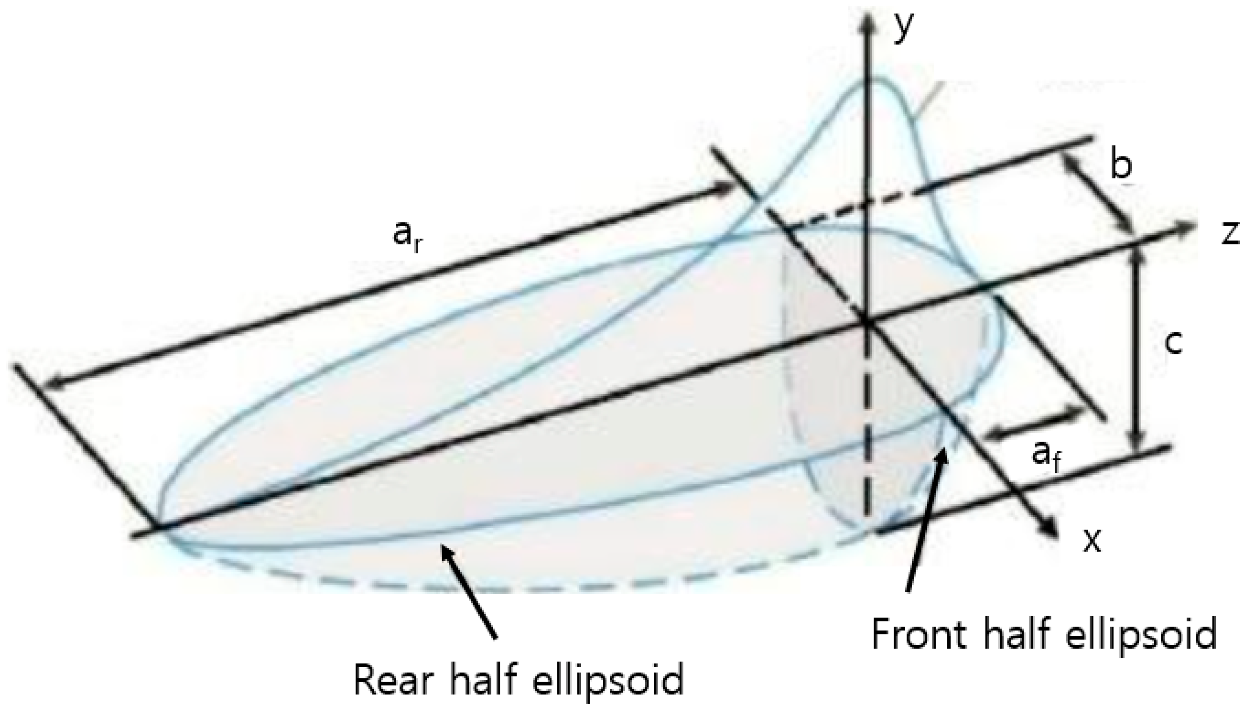
Welding is widely used in the field because of its relatively simple process and excellent quality. However, in the process of melting and cooling a metal, thermoelastic deformation occurs and the deformation is permanent. Therefore, there has been an effort in the industry to reduce welding distortion based on studies to predict welding distortion and incorporate it into the design. To predict welding distortion, empirical methods as well as statistical methods are used [15,16], and there have been studies regarding deformation prediction utilizing computer simulation [17,18,19,20]. To simulate welding through finite element analysis and improve welding quality, it is critical to refine a welding heat source. Therefore, there have been various studies conducted to simulate the welding heat source. Rosenthal estimated a heat source in the form of a point source [21]. This has the advantage of being able to simulate a heat source with a simple formula, but it is not suitable for simulation because the size of the suggested heat source is infinite. A distributed heat source model was applied to solve this problem and the most typical one is the Gaussian heat source model. The Gaussian heat source model has the advantage of being suitable for simulation by changing an infinite heat source into the form of a finite heat source by applying the concept of effective diameter. Among the different types of Gaussian heat source models, the most well-known model is the Goldak heat source model [22], which is a double ellipsoidal heat source model. It consists of two ellipsoids of different sizes, with one ellipsoid representing the front heat source and the other representing the rear heat source. Its shape is shown in Figure 1 and the governing equations are Equations (1)–(5).
Q = μVI
q f x , y , z , t = 6 3 f f Q a f b c π e x p ( 3 ( z v t z 0 2 a f 2 + y 2 c 2 + x 2 b ) )
q r x , y , z , t = 6 3 f r Q a r b c π e x p ( 3 ( z v t z 0 2 a r 2 + y 2 c 2 + x 2 b 2 ) )
f f = 2 a r a f + a r
f r = 2 a f a f + a r
Q: Effective heat energy
μ: Welding efficiency
V: Voltage
I: Current
f f : Fraction of heat deposited at the front ellipsoid
f r : Fraction of heat deposited at the rear ellipsoid
v: Velocity of heat source
af, ar, b, c: Dimension parameters (Shown in Figure 1)
The main variables constituting the Goldak model are the parameters such as af, ar, b and c, and these values are not fixed. They depend on the welding material and welding conditions. For estimating of welding distortion, many research studies have been performed with Goldak’s heat source model. Gharib et al. researched welding distortion of 304L stainless steel of TIG welding with simulating continuous heat source. They compared several fixed conditions with simulation, and verified with experiments [23]. Fu et al. researched the effect of boundary conditions in T-joint welding with Goldak’s heat souce model, also they verified with experiment [24]. Nezamdost et al. researched submerged arc welding with FEM and Goldak’s heat source model [25]. Ghafouri et al. researched welding distortion of ultra-high strength steel with FEM and Goldak’s heat source model [26]. Manurung et al. studied welding distortion after multi pass welding with FEM and Goldak’s heat source model [27]. As the reliability of Goldak’s model were verified with many research studies, that model were applied for estimating the welding distortion.
To perform an analysis with a high level of consistency, the four variables must be appropriate and accurate values that can well reflect actual phenomena. There have been various studies to find appropriate values. Tchoumi used the response surface minimization method based on the results of factorial design of experiments (DOE) to analyze a heat source during TIG welding on stainless steel 316L [28]. Chujutalli derived the peak temperature through FEM by applying a parametric study and found the parameters of the Goldak model based on this value [29]. Podder estimated the key parameters by observing the cross-section after welding experiments [30].
The author of this study derived a welding heat source for the case of welding SS400 by using GMAW in the previous study [31]. After bead-on-plate welding was carried out on SS400 with a thickness of 15.6 mm, its cross-section was compared to the results of heat transfer analysis using FEM to derive appropriate parameters. At this time, the key welding conditions were 200 A (current) and 24 V (voltage), and a multi-island genetic algorithm, which is one of the global optimization algorithms, rather than a typical full factorial method, was applied to derive a heat source model more efficiently. This study has its significance in that the feasibility was analyzed in the study, but it is difficult to apply it to the design and manufacturing of eco-friendly ships because SS400, which cannot be used for a cryogenic storage container, is used. In addition, because the welding efficiency was set as a variable with a wide range, the set of result values appeared in various heat source values. Therefore, it was difficult to classify them one by one and select an optimal value again. Above all, because the objective function was not clearly defined and only the constraint was used, there was an inefficiency in that an additional derivation step was required based on the experience of experts.
This study further improved on the previous study by the author of this study. First, by clarifying the objective function, an optimal value was automatically derived by ranking the results that satisfy the constraints. The solution space was reduced by reducing the range of welding efficiency. In addition, the limitation imposed by the large amount of time that is required to be input, which was the biggest limitation when applying the global optimization method that has to perform more than 2000 comparisons, was overcome by applying a simplified model that can reduce the analysis time per case to less than 10 min when using four CPUs. With this improved research method, a study that can be directly applied to shipbuilding companies that design and manufacture eco-friendly ships using 9% nickel steel, i.e., the material widely used as an LNG fuel tank, was carried out. It is expected that the productivity of shipbuilding companies can be improved when the amount of welding distortion is predicted and reflected in the design based on the welding heat source derived from this study.
2. Welding Experiments and Results

2.1. Welding Material

For this study, 9% nickel steel (ASTM A553-1) was used as a base material and bead-on-plate welding was performed by using flux core arc welding. The welding rod used was AWS A5.14 ERNiMo-8 (KOBELCO, TG-S709S) and a wire with a diameter of 1.2 mm was used. The materials of base metal and welding rod are shown in Table 1 [32], and the mechanical properties of 9% nickel steel are shown in Table 2 [32].

2.2. Welding Experiment Conditions

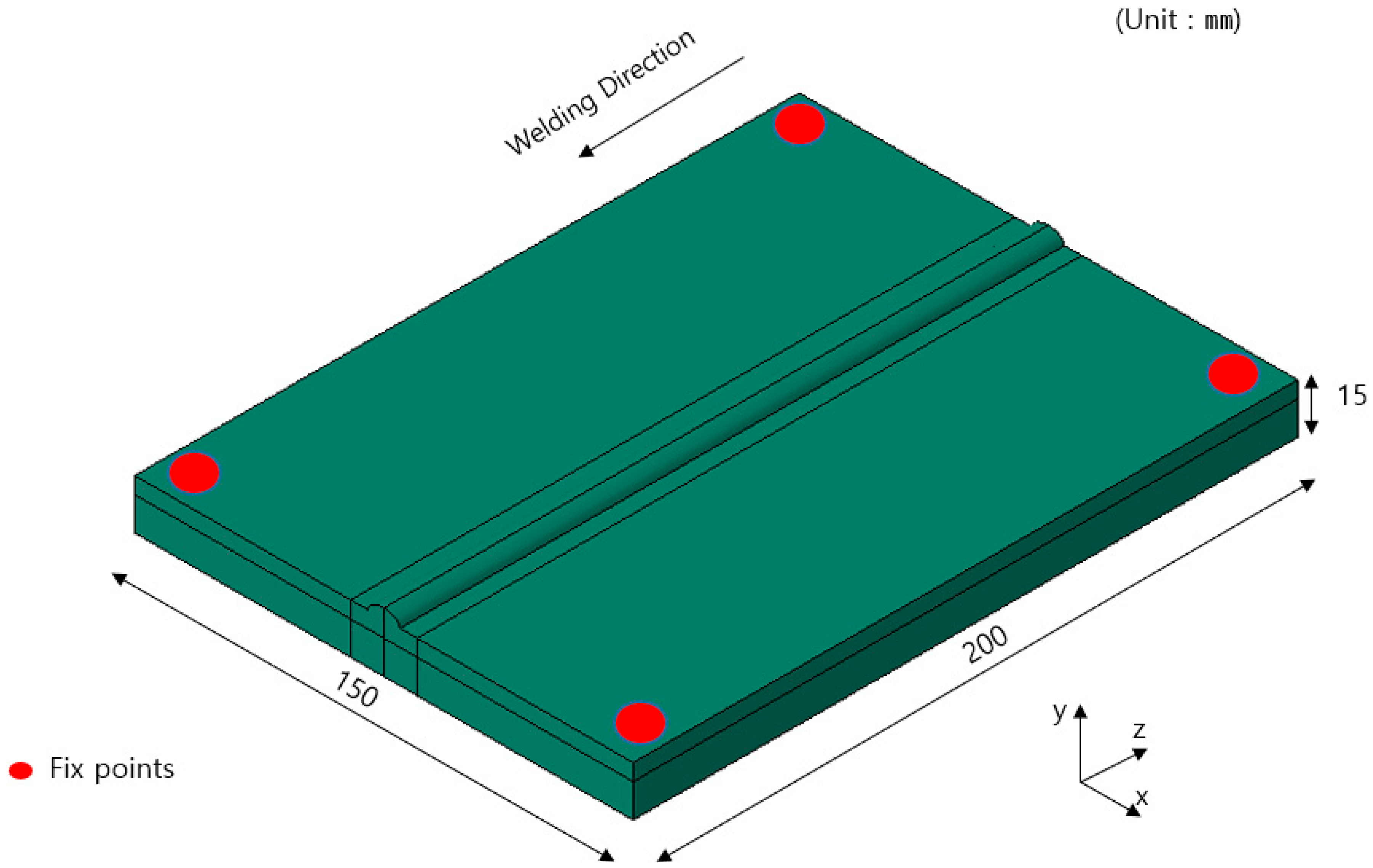
As shown in Figure 2, bottom-view welding was performed with four points fixed and the specimen was cleaned with ethyl alcohol and sand paper before welding to prevent contaminants from affecting the welding. The size of the plate is 150 mm × 200 mm × 15 mm and the welding direction is also shown in Figure 2. For the shielding gas, 99.99% CO2 was used, the Contact Tip Work Distance was 15 mm, and the shielding gas flow rate was fixed at 18 L/min.
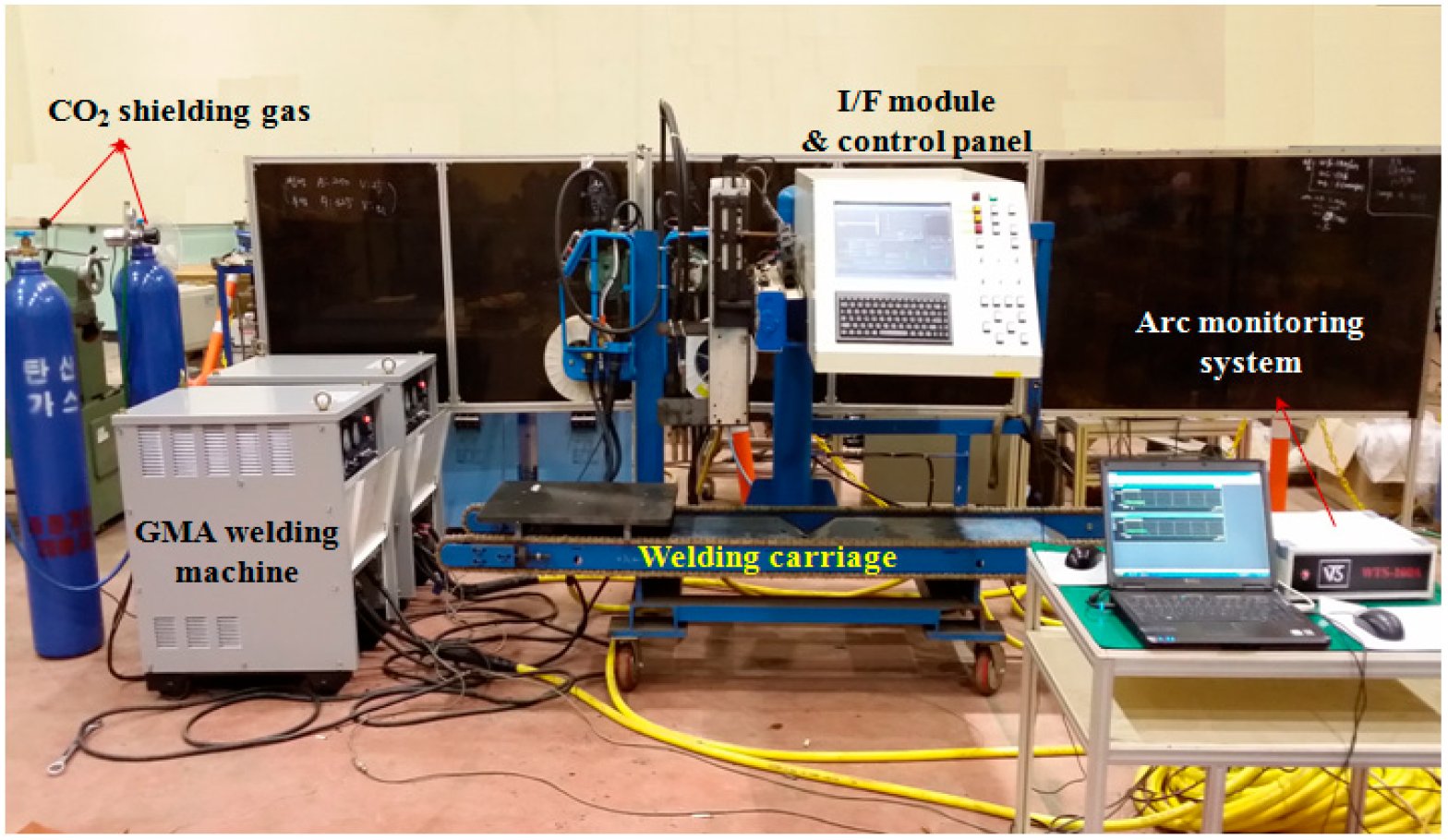
The FCAW equipment used for this experiment is a 600 A class welding machine (ProPAC, HYOSUNG, Mapo-gu, Seoul, Korea) and consists of a torch, a welding feeder, a direct welding carriage and a rail, as shown in Figure 3.
To derive an optimal heat source, the current 150 A, voltage 25 V and welding speed 0.4 m/min were used and bead-on-plate welding was performed under these conditions (Table 3) [33].

2.3. Experiment and Analysis Results

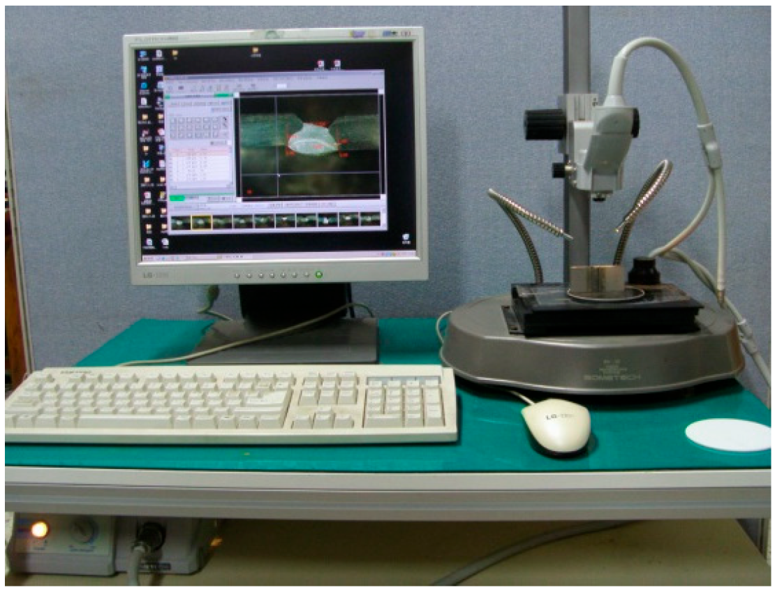
After the bead-on-plate experiment, the center of the weld was cut to observe its cross section. After spraying an etchant prepared with 90% ethanol and 10% nitric acid on the cross section, the shape of the weld was observed using an optical microscope (EGVM 35B, EG Tech, Anyang, Korea) and the major parameters were measured (Figure 4).
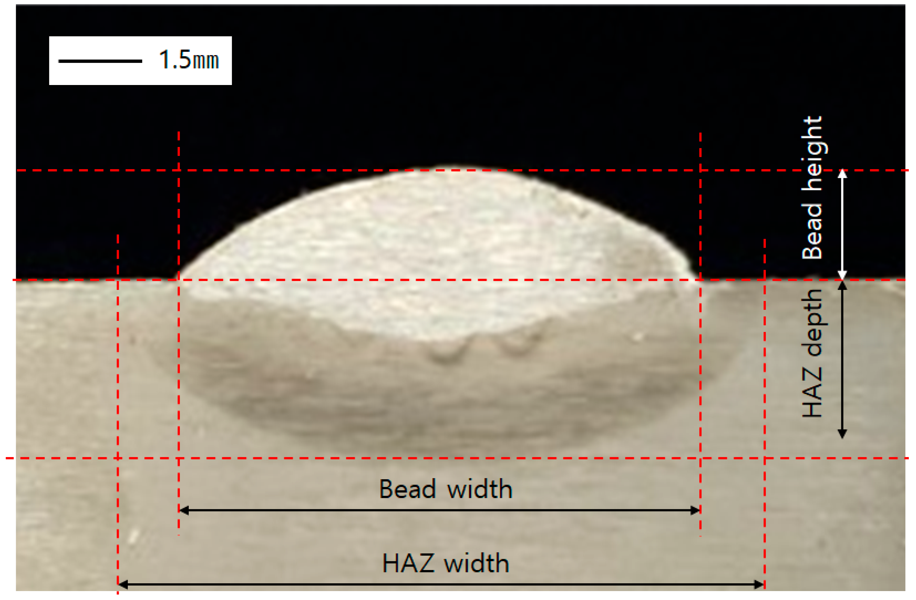
The width and height of the bead and the width and height of the heat affected zone (HAZ) were measured. The shape of the cross section and the definitions of related terms are shown in Figure 5 and the values of key parameters are shown in Table 4, respectively.

3. Finite Element Analysis

3.1. Software

Abaqus (Ver. 2020, Dassault Systems Simulia Corp, Johnston, RI, USA) was used for the welding heat transfer analysis using the finite element method. The moving heat source was implemented utilizing the user subroutine function of Abaqus and Fortran (Ver.17.0, Intel, San Jose, CA, USA) was used to simulate the heat source shape and heat source movement route. Simulation of welding by using both Fortran and Abaqus has been performed in many prior studies and a high level of consistency has been confirmed [34,35,36,37].
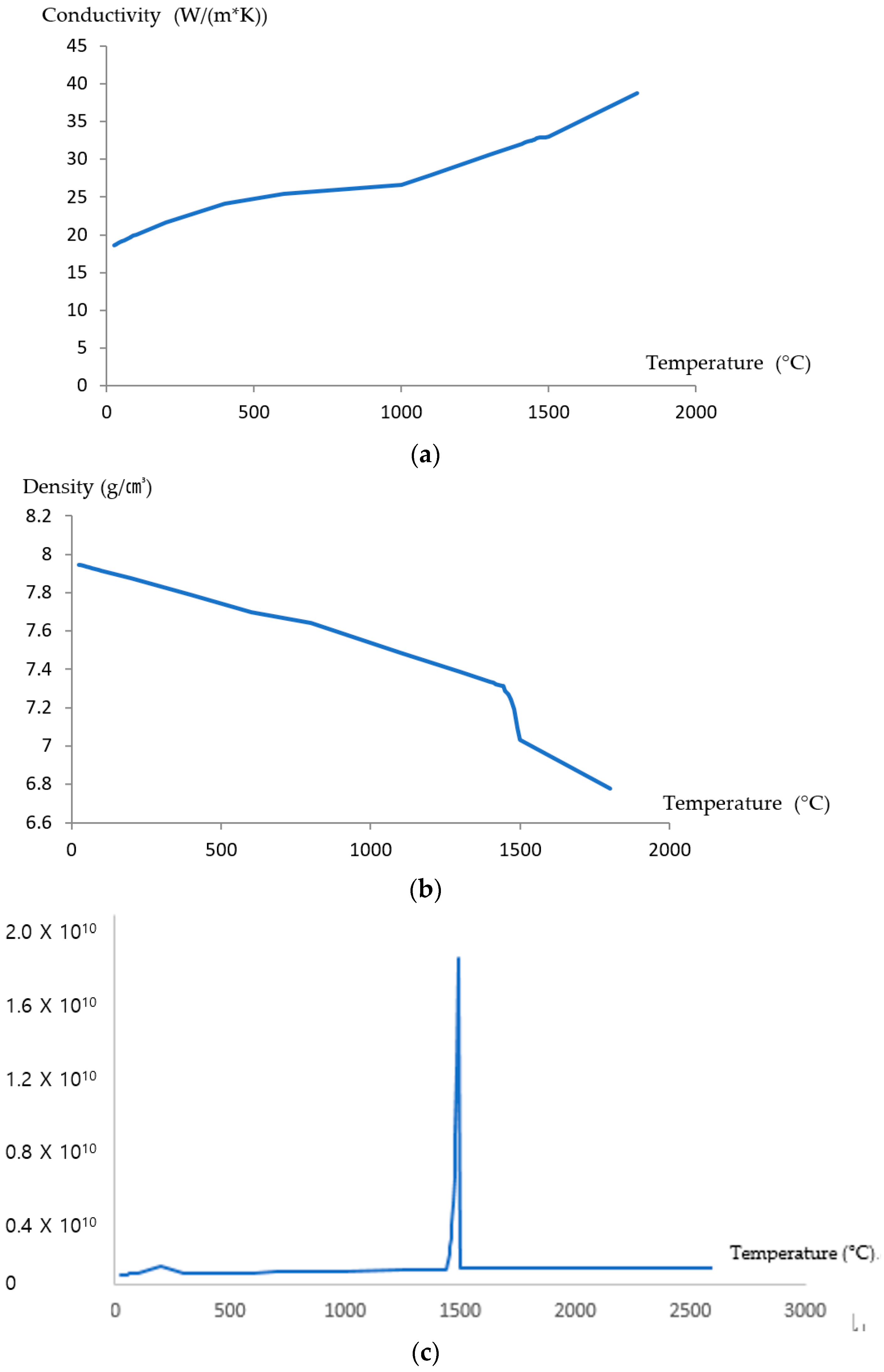
For thermoelasticity analysis, the physical properties at each temperature such as thermal conductivity, specific heat and density, are required. Although some data can be acquired with measurements, some data in the high temperature are hard to obtain. Thus, we used the method which estimates the temperature dependent properties with simulation based on the chemical composition of the metal. As JMatpro has been widely used in other studies [38,39,40], we chose JMatpro to obtain the properties for heat transfer analysis.

3.2. Material Properties by Temperature

As described in Section 3.1, the physical properties, such as thermal conductivity, specific heat and density, are required for the welding heat transfer analysis. Therefore, those physical properties at each temperature were obtained and shown in Figure 6 [41].

3.3. Analytical Models and Boundary Conditions

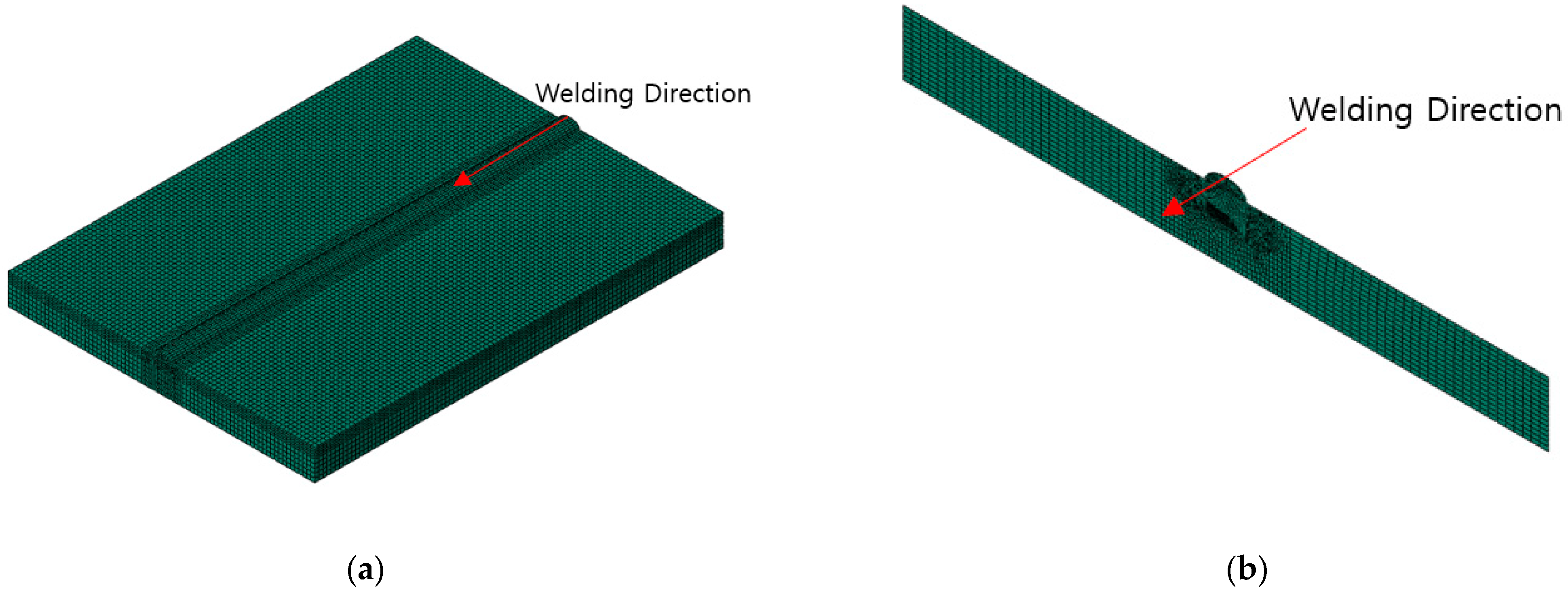
The analysis model was configured based on the experimental model. For an existing model with a width of 150 mm, a length of 200 mm in the welding direction, and a thickness of 15 mm, the welding process was simulated and analyzed using a continuous heat source in the center. The lattice around the beads and the HAZ area was made denser than other areas, so that the temperature distribution at the boundary of HAZ could be more clearly visible. For this purpose, the grid size around HAZ was set to 0.1 mm and the grid size for other areas was set to 1 mm for more efficient analysis (Figure 7).
However, if the length of welding direction is applied as its original 200 mm, the number of meshes exceeds 13,000,000 and a lot of resources are required for the analysis, i.e., more than 2000 analyses, which is not suitable for this study. Therefore, in this study, to reduce the analysis time while securing the analysis quality, a simplified model was created using a 2D shell model for the analysis (Figure 8). Then, the mesh type is DC2D4 and its number is just over 7100. This method was applied to other, similar studies, and the analysis quality was verified [41]. In this study, the optimal heat source derived for verification was applied to the original dimension model to perform heat transfer analysis and the results were compared to the results of the simplified model. As described in Chapter 5.2, it was confirmed that the difference in the dimension of HAZ boundary was within 5.17%, verifying the consistency of the simplified model.
The convective heat transfer coefficient was set to 10 W/m2K, the emissivity was set to 0.8, and the atmospheric temperature was set to 20 °C. Those conditions are referred to in other research of welding for 9% nickel steel [42].

4. Applying Optimization Algorithm

4.1. Process

The main process of this study is to perform heat transfer analysis while changing the parameters of a heat source and to find the appropriate heat source parameters by comparing the resulting temperature distribution to the HAZ confirmed by the welding experiment. For the six parameters including welding efficiency, the Adaptive Simulated Annealing (ASA) method, i.e., one of the global optimization algorithms, was applied because the full-factorial method is inefficient. The Adaptive Simulated Annealing (ASA) is a probabilistic methodology to find an optimal value in the global search space. It is a method derived from annealing that prevents metal defects. At first, it searches for an optimal value with a large variable change range, prevents convergence to a local optimization point, and reduces the variable change range as the optimization progresses to obtain an optimal value. In addition, it allows efficient optimization by automatically adjusting the variable change range according to the speed of optimization. ASA has already been used for design optimization in the electronics and bio industries as well as welding research [43,44,45].

4.2. Software

An optimization algorithm was applied using Isight (Ver. 2020, Dassault Systems Simulia Corp, Johnston, RI, USA) which is from the same company that produces Abaqus that is a finite element method program. The application of an optimization algorithm using Isight has been used in many previous studies [46,47] and both Abaqus and Isight were used in authors’ previous studies [31,41,42,48].

4.3. Target and Constriant

For this study, the HAZ border line and its inside and outside offsets were reflected into the modeling from the modeling stage. The offset distance was set to 0.3 mm and the temperature was checked by selecting 5 points from the inside offset and also 5 points from the outside offset. Because the analysis results are symmetrical, the temperature was actually checked at three individual points (Figure 9).
Here, the important premise is that the points close to the inner offset line must exceed 600 °C [49], which is the HAZ temperature, even for a moment and the points close to the outer offset line must not exceed 600 °C. The above condition was set as a constraint in this optimization process. In my previous study, it was inefficient to derive a result value by directly examining the data satisfying the constraint without clearly suggesting a target for the optimization process. Therefore, in this study, a target for the optimization process was set and the difference between the sum of maximum values at the outer point and the sum of maximum values at the inner point was set as the objective function, as shown in Equation (6).
O b j e c t i v e   f u n t i o n = n = 1 k M a x T Q n T P n
TQn: Temperature of inner check point n
TPn: Temperature of outer check point n
n: Number of check point (n = 1,2,3,4,5)
k: Total number of check points (k = 5)

4.4. Setting a Variable and Its Scope

The goal of this study is to find a condition that satisfies all the constraints of Section 4.3 and maximizes the objective function while changing the parameters of the Goldak model. For the objective, the parameters of the Goldak model, welding efficiency and distance to heat source were set as variables and they are shown in Table 5.
Regarding welding efficiency, as described in the introduction, the range was set to be small in an attempt to address and overcome the problems of previous studies. In a previous study, the welding efficiency was set widely to find a solution in a wide range. This causes a problem whereby a set of parameters are created that satisfy the welding efficiency. For example, the optimal values of various variables were derived, respectively, when the welding efficiency is 0.6, 0.7 and 0.8. Therefore, in this study, the range of welding efficiency of FCAW was reduced and the reference value was set to 0.8 using the results of a previous study [50] and the range was set to 5% (±2.5%). af, ar/af, b and c were set to enable the derivation of optimal values in a relatively wide range, and the height of a base material and the height of a bead were set as a range for the distance to heat source. Actually, the welding efficiency of FCAW for 9% nickel steel was not reported in previous research, so we referred the welding efficiency of FCAW of A-grade steel for ship structures [50].

5. Results and Analysis

5.1. Derivation and Analysis of Optimal Heat Source Parameters

The process described in the previous chapter was used to derive optimal values by comparing 3000 candidates by using Isight. The derived parameter values of the heat source are shown in Table 6 and the temperature values at the checkpoints obtained from the heat transfer analysis are shown in Table 7. At this time, it was found that the thickness direction position of the heat source was the middle point of the bead shape, which was higher than the top position of the base material. It is assumed that this occurs in the process of wire melting and accumulation as welding progresses and it was found that an analysis that considers the final bead shape is necessary when performing the heat transfer analysis of arc welding.
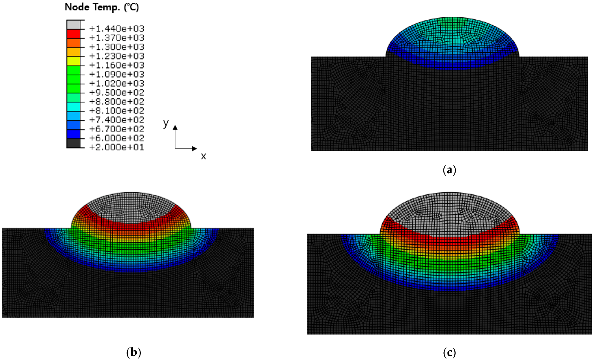
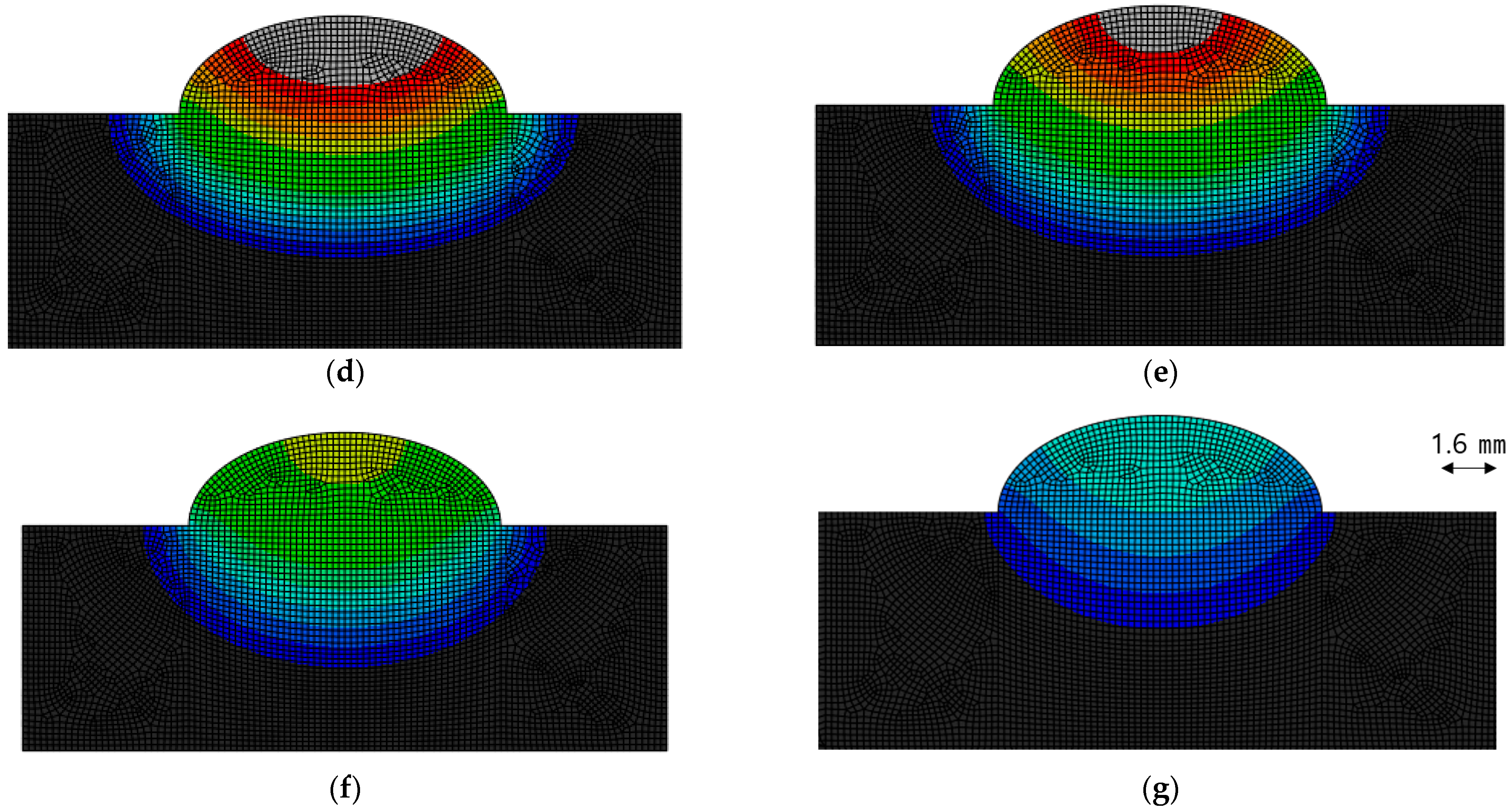
As shown in Table 7, it was found that the maximum temperature did not exceed 600 °C at all three points Pn located at the outer offset, and it was also found that the maximum temperature all exceeded 600 °C at the Qn points located at the inner offset. The analysis results are shown in Figure 10, and they are shown by the timeline of welding. From 0.5 s before the arrival of the heat source until 4.0 s after the heat source has passed, the figures are sequentially shown.
In addition, the key dimensions were checked based on the maximum area of HAZ, and the error rate was checked by comparing the experimental values to the analysis results. In this analysis, it was found that the maximum HAZ width appeared at the moment when the heat source has passed and the maximum HAZ depth appeared 1.6 s after the heat source has passed. The heat transfer analysis results and experimental values are summarized in Figure 11 and Table 8 based on the time when the HAZ appears at its maximum.
Both HAZ depth and HAZ width have an error within 6.28%. An error of 0.261 mm for HAZ depth and 0.597 mm for HAZ width was found, which seems to be due to the initial offset setting to 0.3 mm. It is thought that it is necessary to reduce the range of solutions by reducing the offset setting to find a model with higher consistency.

5.2. Comparison and Analysis with Original Dimension Model with Coarse Meshes

As mentioned in Chapter 3.3, this study derives a heat source model by applying a simplified model to an optimization algorithm. Therefore, its verification with the original dimension model was required and a new analysis was performed and compared based on the derived heat source model. For the original dimension model, the basic mesh size was set to 2 mm for efficient analysis and the mesh size was set to 1 mm from the center to 10 mm on both sides and the mesh type was DC3D8R. The number of meshes is 90300. To compare the simplified model with fine meshes and original dimension model with coarse meshes used in this analysis, the cross-section at the 54 mm position after welding of the original dimension model was checked (Figure 12). The temperature distribution 0.1 s before the heat source passes and the temperature distribution 1.6 s after the heat source passes were checked and compared with the simplified model. The related information is shown in Figure 13 and Figure 14, and Table 9.
As shown in Table 9, the errors of 0.984% for HAZ depth and 2.432% for HAZ width were found 0.1 s before the heat source arrived, and the errors of 5.172% for HAZ depth and 3.676% for HAZ width were found 1.6 s after the heat source has passed. This is thought to be due to the mesh size difference (FEM model: 0.1 mm, original dimension model: 1.0 mm). Because this study sought to find the optimal heat source parameters based on the HAZ size, the simplified FEM model is considered to be reasonable.

6. Conclusions

This study aimed to predict the welding distortion of 9% nickel steel that can be utilized in the cryogenic environment such as LNG storage tanks and devised an optimal design, ultimately to minimize the welding distortion. To predict the welding distortion during flux core arc welding, which is one of the dominant welding methods in the field, the optimal heat source parameters were derived by the more improved method using BOP test, FEM and global optimization algorithm. This research is the first step for those ultimate goals, the main target of this stage is elaborating the parameters of heat source model.
(1)
The Goldak model, which is widely used in the field, was used to help engineers directly apply it to FEM and design. A methodology that can be used to select the parameters of the Goldak model is suggested.
(2)
To address the problems identified in the previous studies of the author of this study, the scope of welding efficiency was reduced, the objective function was clearly defined, and the inefficiency that requires an expert to verify the candidates one by one was eliminated. Therefore, an unexperienced person can also easily utilize this technique in the field.
(3)
Optimal heat source parameters were derived by using BOP experiment, cross-sectional analysis, finite element analysis and global optimization algorithm. When re-analyzed and verified based on the values, an error of up to 6.3% was found between simulation results and experimental values.
(4)
For this study, a simplified model was applied for reducing the resource of simulation. The simplified model was one of main improvements from previous research; the consistency was verified in this manuscript. The maximum error of 5.2% was found in the HAZ boundary when compared to the original dimension model.
The ultimate goal of this study is to predict welding deformation and reflect it in the design stage. For that, the elaboration of the welding heat source should be preceded, and this study is a study on it. For the refinement of the welding heat source, a study was conducted to derive the optimal value using the global optimization algorithm using major parameters as variables. Through this study, a foundational study to derive sophisticated heat sources was established. Based on this study, we plan to derive a heat source model under more diverse conditions, derive a relational expression between parameters for each welding condition, and conduct additional research to predict parameters based on it.

Author Contributions

Conceptualization, C.P.; methodology, C.P. and Y.K.; software, C.P.; validation, J.K.; experiment and result analysis, M.P. and J.S. (Joonsik Son); investigation, J.K., Y.K. and S.-M.J.; resources, S.-M.J.; data curation, J.-H.K.; writing—original draft preparation, C.P., J.S. (Jihoon Shin) and S.-M.J.; writing—review and editing: J.K., M.-H.K. and J.-H.K.; visualization, C.P.; supervision, J.K.; M.-H.K. and J.-H.K.; project administration, J.K.; funding acquisition, J.K. All authors have read and agreed to the published version of the manuscript.

Funding

This study has been conducted with the support of the Ministry of Oceans and Fisheries as “Development of liquid hydrogen-based leisure fishing boats (20220037, PNK22870)”.

Institutional Review Board Statement

Not applicable.

Informed Consent Statement

Not applicable.

Data Availability Statement

The data presented in this study are available on request from the corresponding author.

Conflicts of Interest

The authors declare no conflict of interest.

References

  1. Park, T.-U.; Jung, D.-H.; Park, J.-H.; Kim, J.-H.; Han, I.-W. Changes in the Mechanical Properties and Microstructure of High Manganese Steel by High Heat Input Welding and General Welding Processes. J. Weld. Join. 2022, 40, 33–39. [Google Scholar] [CrossRef]
  2. International Energy Agency. Net Zero by 2050—A Roadmap for the Global Energy Sector; International Energy Agency: Paris, France, 2021. [Google Scholar]
  3. International Energy Agency. World Energy Outlook 2021; OECD: Paris, France, 2021. [Google Scholar] [CrossRef]
  4. Pfoser, S.; Schauer, O.; Costa, Y. Acceptance of LNG as an Alternative Fuel: Determinants and Policy Implications. Energy Policy 2018, 120, 259–267. [Google Scholar] [CrossRef]
  5. Vivoda, V. LNG Import Diversification and Energy Security in Asia. Energy Policy 2019, 129, 967–974. [Google Scholar] [CrossRef]
  6. Paik, K.-W. South Korea’s Energy Policy Change and the Implications for Its LNG Imports; Oxford Institute for Energy Studies: Oxford, UK, 2018. [Google Scholar] [CrossRef] [Green Version]
  7. Kumar, S.; Kwon, H.-T.; Choi, K.-H.; Lim, W.; Cho, J.H.; Tak, K.; Moon, I. LNG: An Eco-Friendly Cryogenic Fuel for Sustainable Development. Appl. Energy 2011, 88, 4264–4273. [Google Scholar] [CrossRef]
  8. Smyshlyaeva, K.I.; Rudko, V.A.; Kuzmin, K.A.; Povarov, V.G. Asphaltene Genesis Influence on the Low-Sulfur Residual Marine Fuel Sedimentation Stability. Fuel 2022, 328, 125291. [Google Scholar] [CrossRef]
  9. Smyshlyaeva, K.I.; Rudko, V.A.; Povarov, V.G.; Shaidulina, A.A.; Efimov, I.; Gabdulkhakov, R.R.; Pyagay, I.N.; Speight, J.G. Influence of Asphaltenes on the Low-Sulphur Residual Marine Fuels’ Stability. J. Mar. Sci. Eng. 2021, 9, 1235. [Google Scholar] [CrossRef]
  10. Patel, D. Developments in LNG storage: Overview of LNG storage tanks. In Proceedings of the LNG 2000 Conference, London, UK, 1 January–2 February 2000. [Google Scholar]
  11. Kang, S.-K. Crack Propagation Characterization Applying High Manganese Austenitic Steel to Independent Type B Tank. J. Weld. Join. 2022, 40, 9–15. [Google Scholar] [CrossRef]
  12. Yun, T.-J.; Oh, W.-B.; Lee, B.-R.; Lee, C.-W.; Na, H.-H.; Choi, J.-S.; Kim, I.-S. A Study on Optimization of Fillet in Laser Welding Process for 9% Ni Steel Using Gradient-Based Optimization Algorithm. J. Weld. Join. 2020, 38, 485–492. [Google Scholar] [CrossRef]
  13. Park, J.-H.; Kim, Y.-H.; Baek, H.-J.; Cho, S.-M. A Study on Process Development of Super-TIG Welding for 9% Nickel Steel with Alloy 625. J. Manuf. Process. 2019, 40, 140–148. [Google Scholar] [CrossRef]
  14. Kim, B.E.; Park, J.Y.; Lee, J.S.; Lee, J.I.; Kim, M.H. Effects of the Welding Process and Consumables on the Fracture Behavior of 9 Wt.% Nickel Steel. Exp. Technol. 2020, 44, 175–186. [Google Scholar] [CrossRef]
  15. Seong, W.J. Prediction and Characteristics of Angular Distortion in Multi-Layer Butt Welding. Materials 2019, 12, 1435. [Google Scholar] [CrossRef] [PubMed] [Green Version]
  16. Kim, C.-H.; Yang, J.-S.; Kim, H.-K. A Study on the Deformation Control of Thin Plate Block by Applying the Tensioning Method. J. Weld. Join. 2008, 25, 59–63. [Google Scholar] [CrossRef]
  17. Rajesh, S.R.; Yoo, J.; Park, J.; Choi, D. Thermal Deformation Analysis Methodology Development for Inconel Overlaying. J. Weld. Join. 2022, 40, 107–117. [Google Scholar] [CrossRef]
  18. Li, X.; Hu, L.; Deng, D. Influence of Contact Behavior on Welding Distortion and Residual Stress in a Thin-Plate Butt-Welded Joint Performed by Partial-Length Welding. Thin Walled Struct. 2022, 176, 109302. [Google Scholar] [CrossRef]
  19. Zhang, K.; Dong, W.; Lu, S. Residual Stress and Distortion in Thick-Plate Weld Joint of AF1410 Steel: Finite Element Simulations and Experimental Studies. Mater. Res. Express 2022, 9, 016524. [Google Scholar] [CrossRef]
  20. Arora, H.; Singh, R.; Singh Brar, G. Prediction of Temperature Distribution and Displacement of Carbon Steel Plates by FEM. Mater. Today Proc. 2019, 18, 3380–3386. [Google Scholar] [CrossRef]
  21. Rosenthal, D. The Theory of Moving Sources of Heat and Its Application of Metal Treatments. Trans. ASME 1946, 68, 849–866. [Google Scholar]
  22. Goldak, J.; Chakravarti, A.; Bibby, M. A New Finite Element Model for Welding Heat Sources. Metall. Trans. B 1984, 15, 299–305. [Google Scholar] [CrossRef]
  23. Gharib, A.R.; Biglari, F.R.; Shafaie, M.; Kokabi, A.H. Experimental and Numerical Investigation of Fixture Time on Distortion of Welded Part. Int. J. Adv. Manuf. Technol. 2019, 104, 1121–1131. [Google Scholar] [CrossRef]
  24. Fu, G.; Lourenco, M.I.; Duan, M.; Estefen, S.F. Effect of Boundary Conditions on Residual Stress and Distortion in T-Joint Welds. J. Constr. Steel Res. 2014, 102, 121–135. [Google Scholar] [CrossRef]
  25. Nezamdost, M.R.; Esfahani, M.R.N.; Hashemi, S.H.; Mirbozorgi, S.A. Investigation of Temperature and Residual Stresses Field of Submerged Arc Welding by Finite Element Method and Experiments. Int. J. Adv. Manuf. Technol. 2016, 87, 615–624. [Google Scholar] [CrossRef] [Green Version]
  26. Ghafouri, M.; Ahn, J.; Mourujärvi, J.; Björk, T.; Larkiola, J. Finite Element Simulation of Welding Distortions in Ultra-High Strength Steel S960 MC Including Comprehensive Thermal and Solid-State Phase Transformation Models. Eng. Struct. 2020, 219, 110804. [Google Scholar] [CrossRef]
  27. Manurung, Y.H.P.; Lidam, R.N.; Rahim, M.R.; Zakaria, M.Y.; Redza, M.R.; Sulaiman, M.S.; Tham, G.; Abas, S.K. Welding Distortion Analysis of Multipass Joint Combination with Different Sequences Using 3D FEM and Experiment. Int. J. Press. Vessel. Pip. 2013, 111–112, 89–98. [Google Scholar] [CrossRef]
  28. Tchoumi, T.; Peyraut, F.; Bolot, R. Influence of the Welding Speed on the Distortion of Thin Stainless Steel Plates—Numerical and Experimental Investigations in the Framework of the Food Industry Machines. J. Mater. Process. Technol. 2016, 229, 216–229. [Google Scholar] [CrossRef]
  29. Chujutalli, J.H.; Lourenço, M.I.; Estefen, S.F. Experimental-Based Methodology for the Double Ellipsoidal Heat Source Parameters in Welding Simulations. Mar. Syst. Ocean. Technol. 2020, 15, 110–123. [Google Scholar] [CrossRef]
  30. Podder, D.; Mandal, N.R.; Das, S. Heat Source Modeling and Analysis of Submerged Arc Welding. Weld. J. 2004, 93, 183–192. [Google Scholar]
  31. Pyo, C.; Kim, J.; Kim, J. Estimation of Heat Source Model’s Parameters for GMAW with Non-Linear Global Optimization—Part I: Application of Multi-Island Genetic Algorithm. Metals 2020, 10, 885. [Google Scholar] [CrossRef]
  32. Park, M.; Kim, J.; Pyo, C. A Study on Heat Input Control and a Quality Evaluation Algorithm to Prevent Toughness Deterioration of the Heat-Affected Zone in the Fiber Laser Welding Process of ASTM A553-1 (9% Nickel Steel) Material. Metals 2022, 12, 1195. [Google Scholar] [CrossRef]
  33. Park, M.; Kim, J.; Pyo, C. A Study on the Development of an Optimization Algorithm and Determination Procedure for Toughness Deterioration Characteristics through Flux Core Arc Heat Input Control of ASTM A553-1 (9% Nickel Steel). Metals 2022, 12, 1213. [Google Scholar] [CrossRef]
  34. Deng, D. FEM Prediction of Welding Residual Stress and Distortion in Carbon Steel Considering Phase Transformation Effects. Mater. Des. 2009, 30, 359–366. [Google Scholar] [CrossRef]
  35. Ahmad, A.S.; Wu, Y.; Gong, H.; Nie, L. Finite Element Prediction of Residual Stress and Deformation Induced by Double-Pass TIG Welding of Al 2219 Plate. Materials 2019, 12, 2251. [Google Scholar] [CrossRef] [PubMed] [Green Version]
  36. Pankaj, P.; Sawarkar, P.S.; Tiwari, A.; Biswas, P.; Pal, S. Three Dimensional FE Thermal Analysis for Friction Stir Welding of Low Carbon Steel. Mater. Today Proc. 2021, 41, 902–907. [Google Scholar] [CrossRef]
  37. Asadi, P.; Alimohammadi, S.; Kohantorabi, O.; Fazli, A.; Akbari, M. Effects of Material Type, Preheating and Weld Pass Number on Residual Stress of Welded Steel Pipes by Multi-Pass TIG Welding (C-Mn, SUS304, SUS316). Therm. Sci. Eng. Prog. 2020, 16, 100462. [Google Scholar] [CrossRef]
  38. Erişir, E.; Ayhan, I.I.; Güney, C.; Alan, E.; Dürger, N.B.; Ün, S. Microstructure and Phase Transformations in High-Strength Bainitic Forging Steel. J. Mater. Eng. Perform. 2021, 30, 3458–3467. [Google Scholar] [CrossRef]
  39. Dai, S.; Wang, Y.; Chen, F.; Yu, X.; Zhang, Y. Design of New Biomedical Titanium Alloy Based on D-Electron Alloy Design Theory and JMatPro Software. Trans. Nonferrous Met. Soc. China 2013, 23, 3027–3032. [Google Scholar] [CrossRef]
  40. Saunders, N.; Guo, U.K.Z.; Li, X.; Miodownik, A.P.; Schillé, J.-P. Using JMatPro to Model Materials Properties and Behavior. JOM 2003, 55, 60–65. [Google Scholar] [CrossRef]
  41. Pyo, C. Research for Estimation of Heat Source Model Parameters with Simplified FE Model & Global Optimization Algorithm Part II: Cost Reduction of Analysis with Simplified Model. J. Korean Soc. Mech. Technol. 2020, 22, 643–651. [Google Scholar]
  42. Pyo, C.; Kim, J.; Kim, D.S. A Study on Welding Deformation in Fiber Laser Welding of 9% Nickel Steel through Finite Element Analysis Part I: Implementation of Welding Heat Source Model. Processes 2021, 9, 2188. [Google Scholar] [CrossRef]
  43. Singla, S.; Saini, V. Parameter Optimization of SAW in Hardfacing Process Using Hybrid Approach of Adaptive Stimulated Annealing and Neural Networks. Asian J. Eng. Appl. Technol. 2012, 1, 16–20. [Google Scholar]
  44. Aarts, E.; Korst, J.; Michiels, W. Simulated Annealing. In Search Methodologies: Introductory Tutorials in Optimization and Decision Support Techniques; Burke, E.K., Kendall, G., Eds.; Springer US: Boston, MA, USA, 2005; pp. 187–210. [Google Scholar] [CrossRef]
  45. Lin, J.; Zhong, Y.; Li, E.; Lin, X.; Zhang, H. Multi-Agent Simulated Annealing Algorithm with Parallel Adaptive Multiple Sampling for Protein Structure Prediction in AB off-Lattice Model. Appl. Soft Comput. 2018, 62, 491–503. [Google Scholar] [CrossRef]
  46. Wang, W.; Mo, R.; Zhang, Y. Multi-Objective Aerodynamic Optimization Design Method of Compressor Rotor Based on Isight. Procedia Eng. 2011, 15, 3699–3703. [Google Scholar] [CrossRef]
  47. Hahn, Y.; Cofer, J. Design Study of Dovetail Geometries of Turbine Blades Using Abaqus and Isight; Volume 7: Structures and Dynamics, Parts A and B. In Proceedings of the ASME Turbo Expo 2012: Turbine Technical Conference and Exposition, Copenhagen, Denmark, 11–15 June 2012; pp. 11–20. [Google Scholar]
  48. Pyo, C.; Kim, J.; Kim, Y.; Kim, M. A Study on a Representative Heat Source Model for Simulating Laser Welding for Liquid Hydrogen Storage Containers. Mar. Struct. 2022, 86, 103260. [Google Scholar] [CrossRef]
  49. Rios, M.C.G.; da Cruz Payão Filho, J.; Farias, F.W.C.; Passos, A.V.; Moraes e Oliveira, V.H.P. Microstructural Characterization of the Physical Simulated and Welded Heat-Affected Zone of 9% Ni Steel Pipe. J. Mater. Res. Technol. 2022, 17, 3033–3046. [Google Scholar] [CrossRef]
  50. Oh, J.; Kim, Y.; Park, P.; Bang, H. A Study on the Thermal and Mechanical Characteristic of Hybrid Welded Ship Structure A-Grade Steel. Int. J. Ocean. Syst. Eng. 2007, 21, 64–68. [Google Scholar]
Figure 1. Heat distribution of Goldak Model [22].
Jmse 10 01810 g001
Figure 2. Schematic diagram of welding.
Jmse 10 01810 g002
Figure 3. Flux core arc welding equipment.
Jmse 10 01810 g003
Figure 4. Optical microscope.
Jmse 10 01810 g004
Figure 5. Define the shape of cross section and key parameters.
Jmse 10 01810 g005
Figure 6. Material properties of 9% nickel steel by temperature. (a) Conductivity. (b) Density. (c) Specific heat.
Jmse 10 01810 g006
Figure 7. Mesh shape by zone.
Jmse 10 01810 g007
Figure 8. Original dimension model and simplified model. (a) Original dimension model (with coarse meshes). (b) Simplified model (with fine meshes).
Jmse 10 01810 g008
Figure 9. Offset shape, temperature checking position, definition of distance to heat source.
Jmse 10 01810 g009
Figure 10. Temperature distribution by timeline before and after welding. Times were (a) −0.5 s (before the heat source arrives); (b) −0.1 s (before the heat source arrives); (c) 0 s (when the heat source is directly above); (d) 0.5 s elapsed; (e) 1.0 s elapsed; (f) 2.0 s elapsed; (g) 4.0 s elapsed.
Jmse 10 01810 g010aJmse 10 01810 g010b
Figure 11. Heat transfer analysis results. Times were (a) 0 s after the welding heat source has passed (Max HAZ width); (b) 1.6 s after the welding heat source has passed (Max HAZ Depth).
Jmse 10 01810 g011
Figure 12. Iso view and section check position in the heat transfer analysis for the original dimension model.
Jmse 10 01810 g012
Figure 13. Comparison of temperature distribution 0.1 s before the heat source arrives. (a) Simplified model with fine meshes. (b) Original dimension model with coarse meshes.
Jmse 10 01810 g013
Figure 14. Comparison of temperature distribution 1.6 s after the heat source has passed. (a) Simplified model with fine meshes. (b) Original dimension model with coarse meshes.
Jmse 10 01810 g014
Table 1. Chemical composition of base metal and filler wire (wt. %) [32].
CSiMnSPNiFe
Parent material0.050.670.0040.0030.259.02Bal.
Welding consumables0.020.020.10.0010.00169.8Bal.
Table 2. Mechanical properties of 9% nickel steel [32].
Yield Strength (MPa)Tensile Strength (MPa)Elongation (%)Hardness (HV)
651.6701.126.6243
Table 3. FCAW parameters and experimental condition.
Current (A)Voltage (V)Welding Power (kW)Welding Speed (m/min)
150253.750.4
Table 4. Values of key parameters.
Bead Height (mm)Bead Width (mm)HAZ Depth (mm)HAZ Width (mm)
2.909.684.1415.74
Table 5. Variables and ranges.
VariablesLower BoundUpper Bound
μ (W/W)0.780.82
af (mm)1.015.0
ar/af (mm/mm)1.57.0
b (mm)1.015.0
c (mm)1.015.0
L (Distance to heat source, mm)02.9 (Height of bead)
Table 6. Derived heat source parameters.
VariablesValue
μ (W/W)0.780
af (mm)9.297
ar (mm)63.053
b (mm)14.267
c (mm)8.522
L (mm)1.242
Table 7. Maximum temperature at each checkpoint per welding condition.
TemperatureValue (°C)
P1517.82
P2544.26
P3599.99
Q1602.06
Q2628.79
Q3681.06
Table 8. HAZ dimension and comparison.
HAZ DepthHAZ Width
FEM (mm)Experiment (mm)Difference (%)FEM (mm)Experiment (mm)Difference (%)
4.4014.1406.2815.14315.7403.79
Table 9. Temperature 600 °C line comparison of simplified model and actual model.
DepthWidth
Simplified Model (mm)Original Dimension Model (mm)Difference (%)Simplified Model (mm)Original Dimension Model (mm)Difference (%)
Before3.4543.4200.98414.04613.7052.432
0.1 sec
After4.4404.2105.17212.83512.3633.676
1.6 sec
Publisher’s Note: MDPI stays neutral with regard to jurisdictional claims in published maps and institutional affiliations.