


Research on Structural Failure Analysis and Strengthening Design of Offshore Wind Turbine Blades

Abstract
1. Introduction
2. Structural Failure Analysis of Wind Turbine Blades
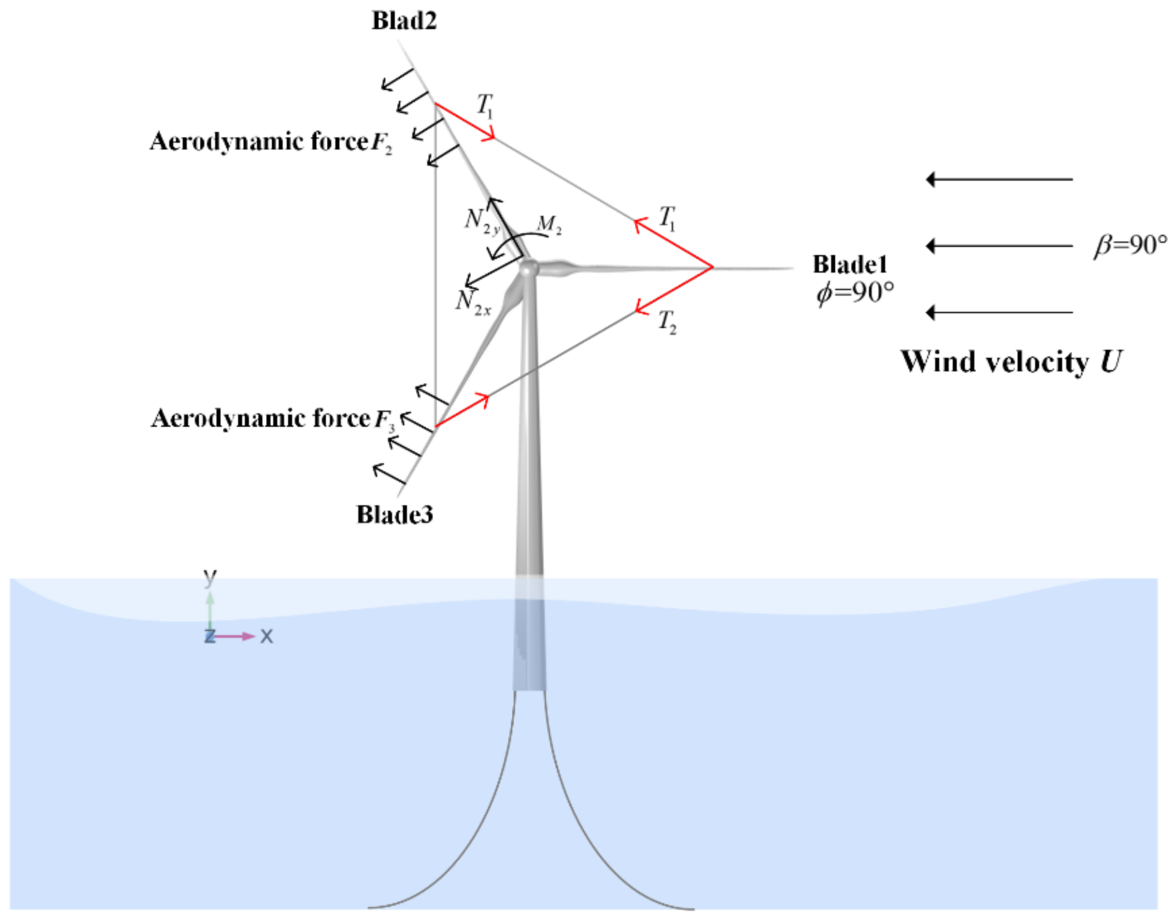
3. Wind Load Reduction Design
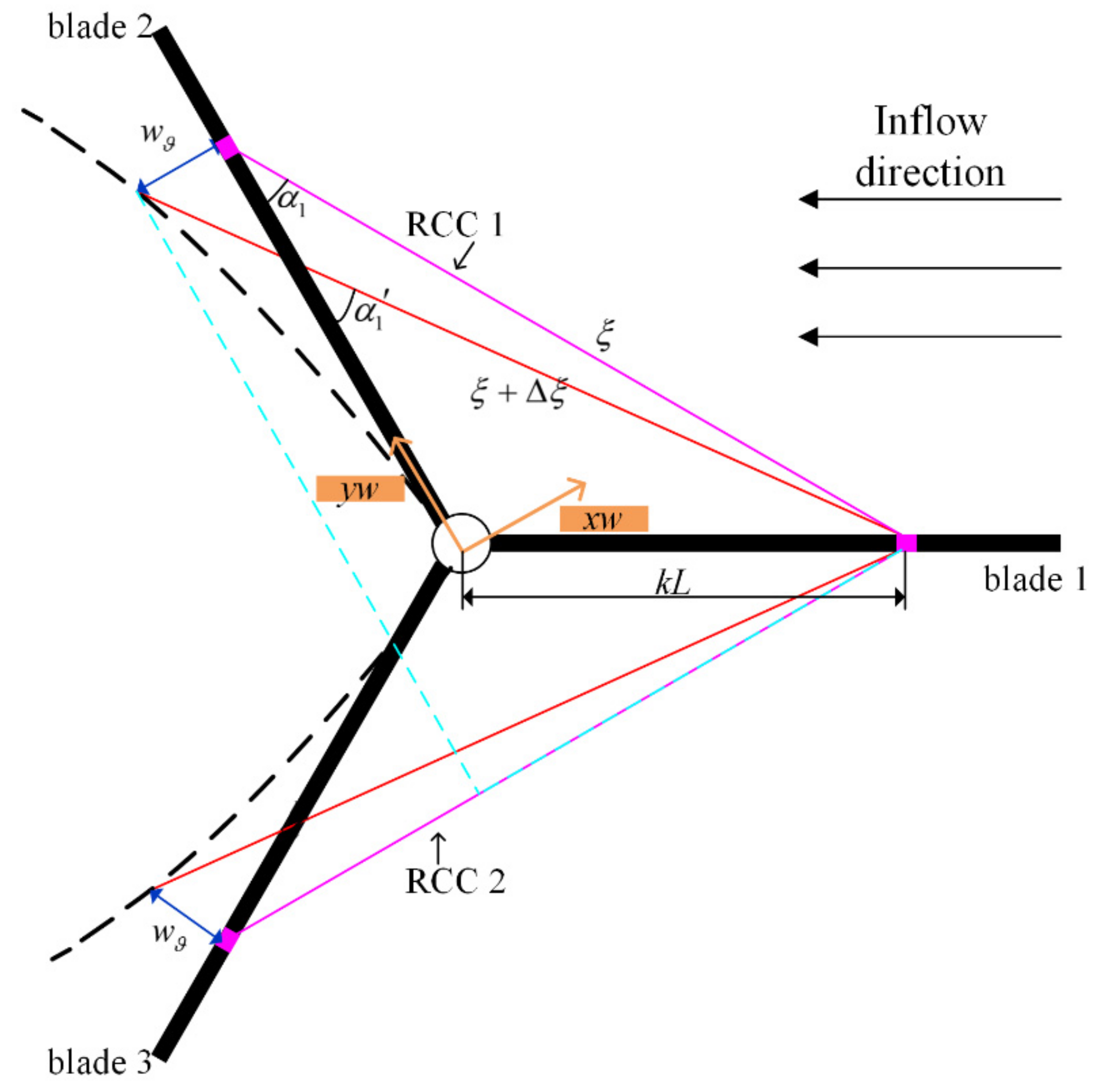
3.1. Structure Strengthing Design of Reinforcing Cable Component(RCC)
3.2. Wind Load Reduction Analysis
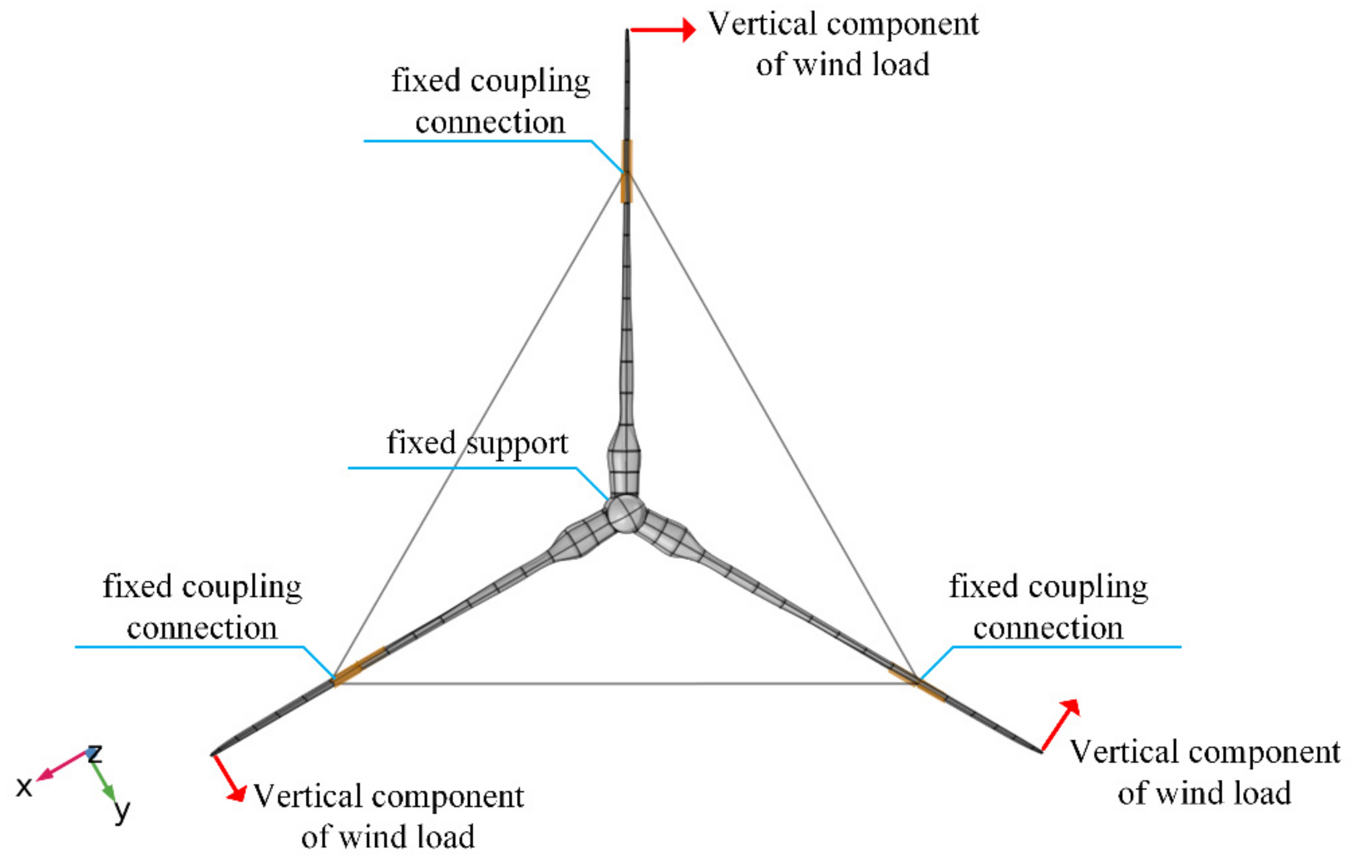
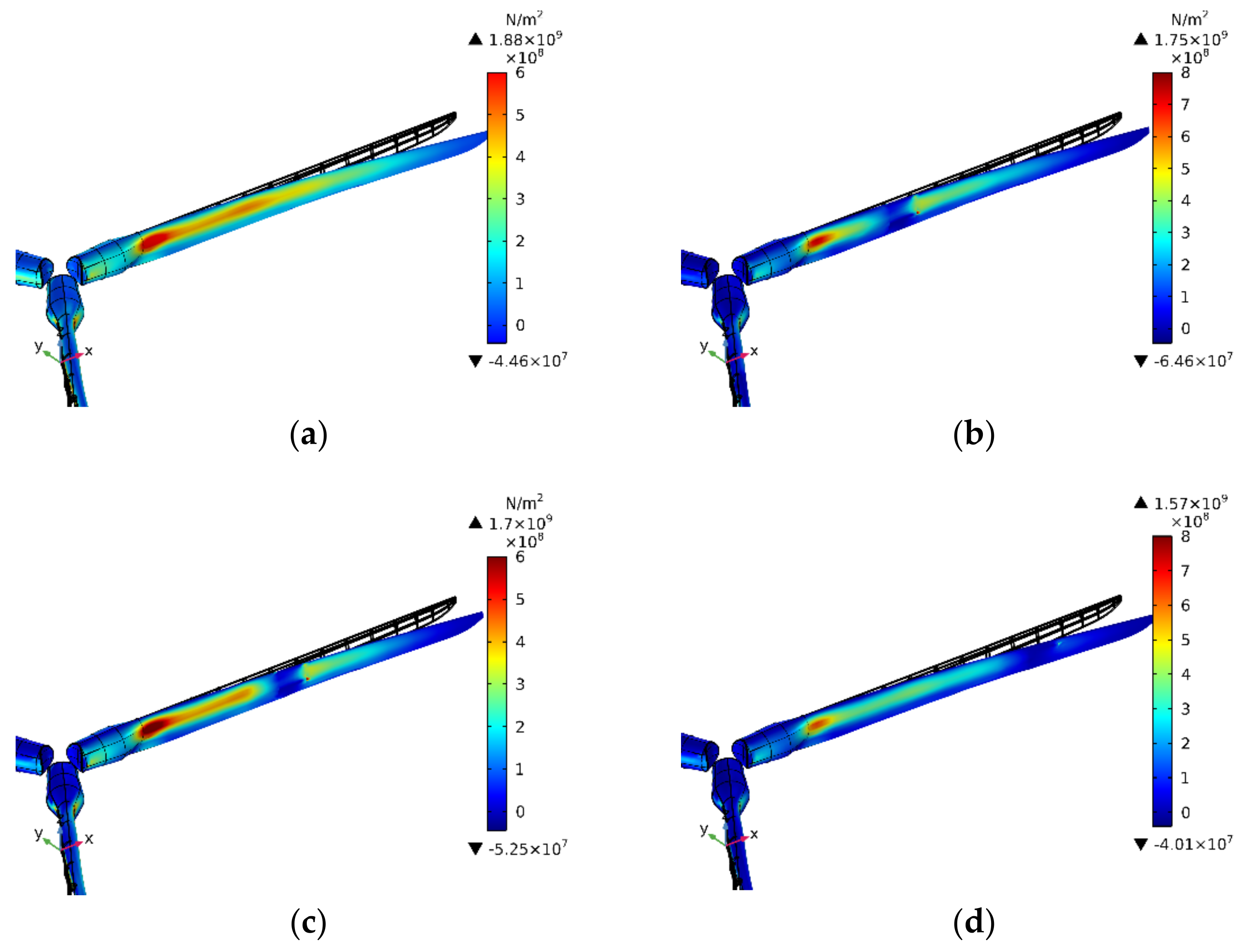
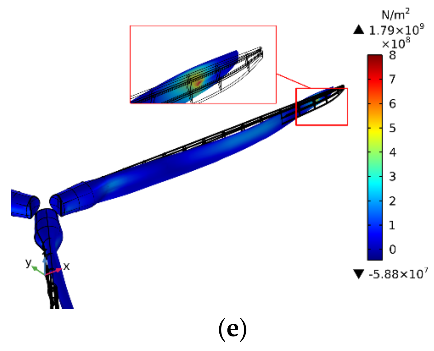
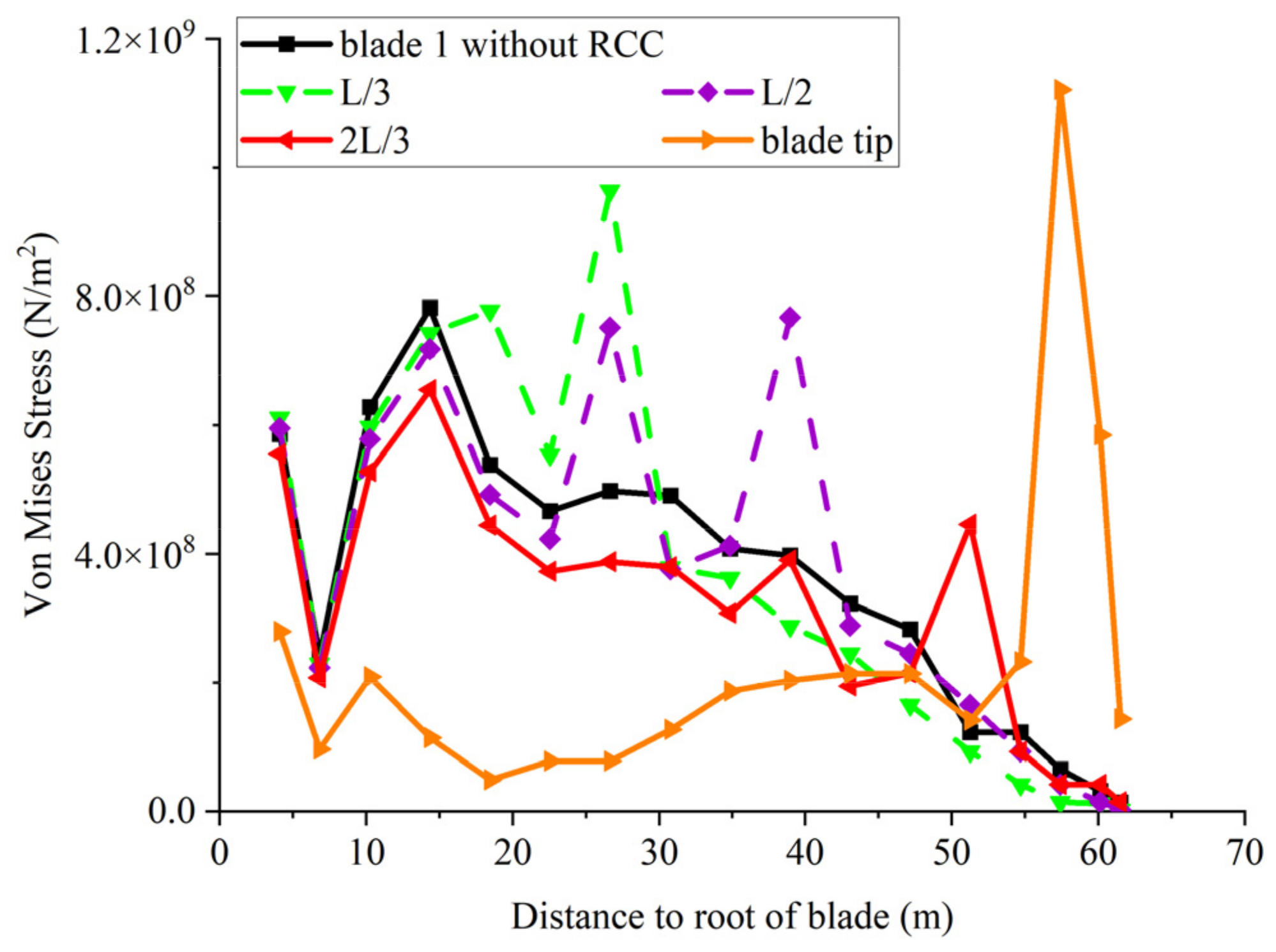
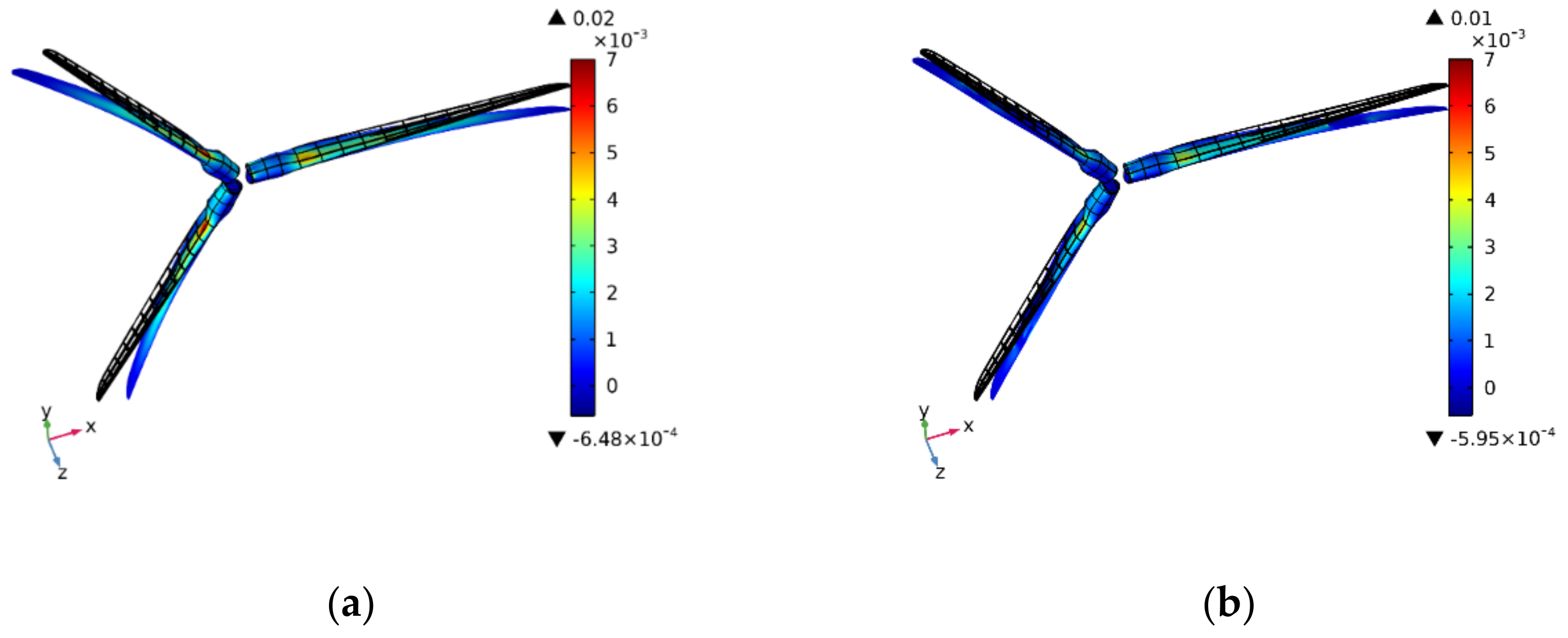
4. Simulation Results from FE Models
4.1. Wind Turbine Blade Model
4.2. Results and Discussion
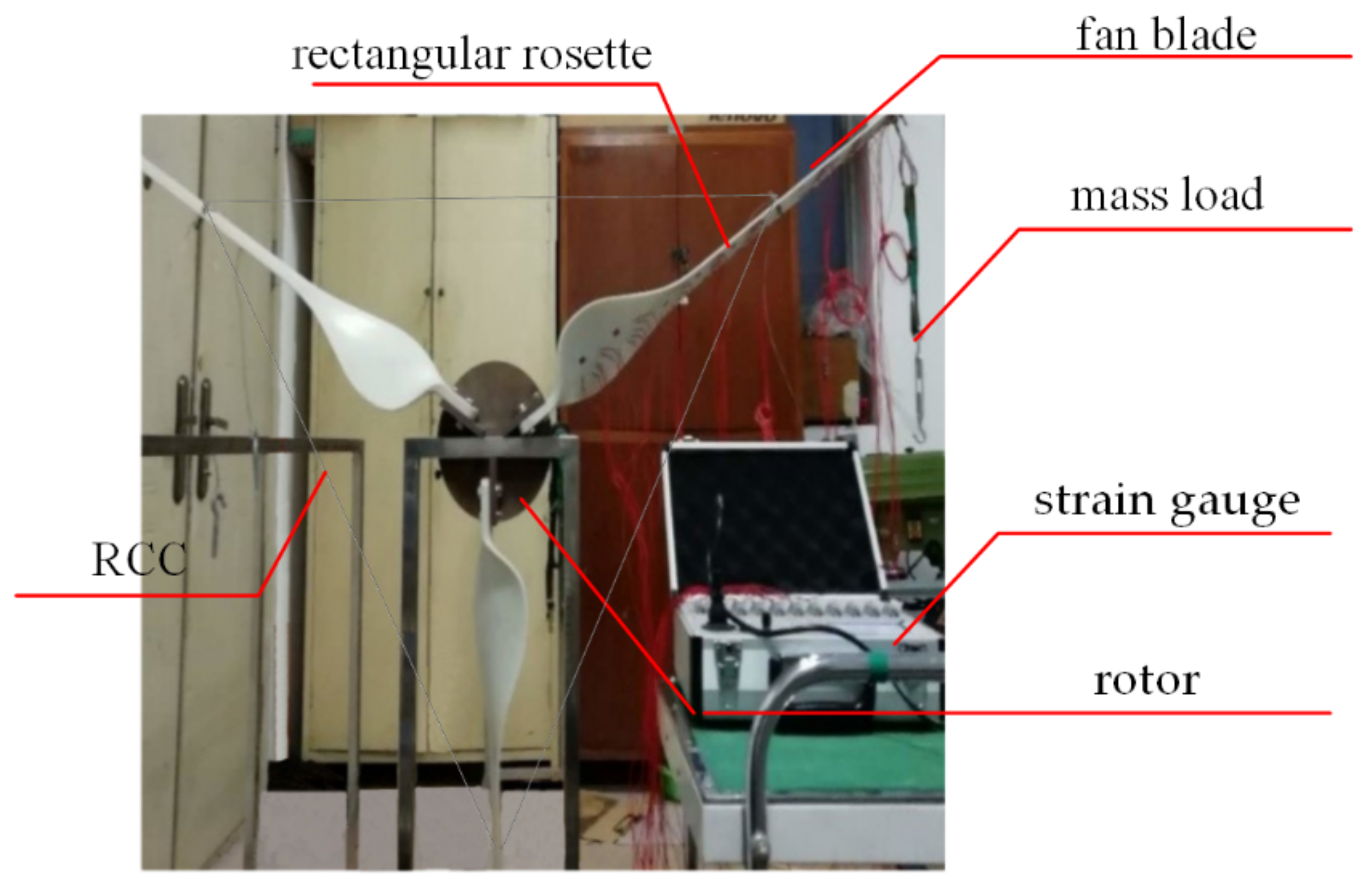
5. Static Load Strain Test
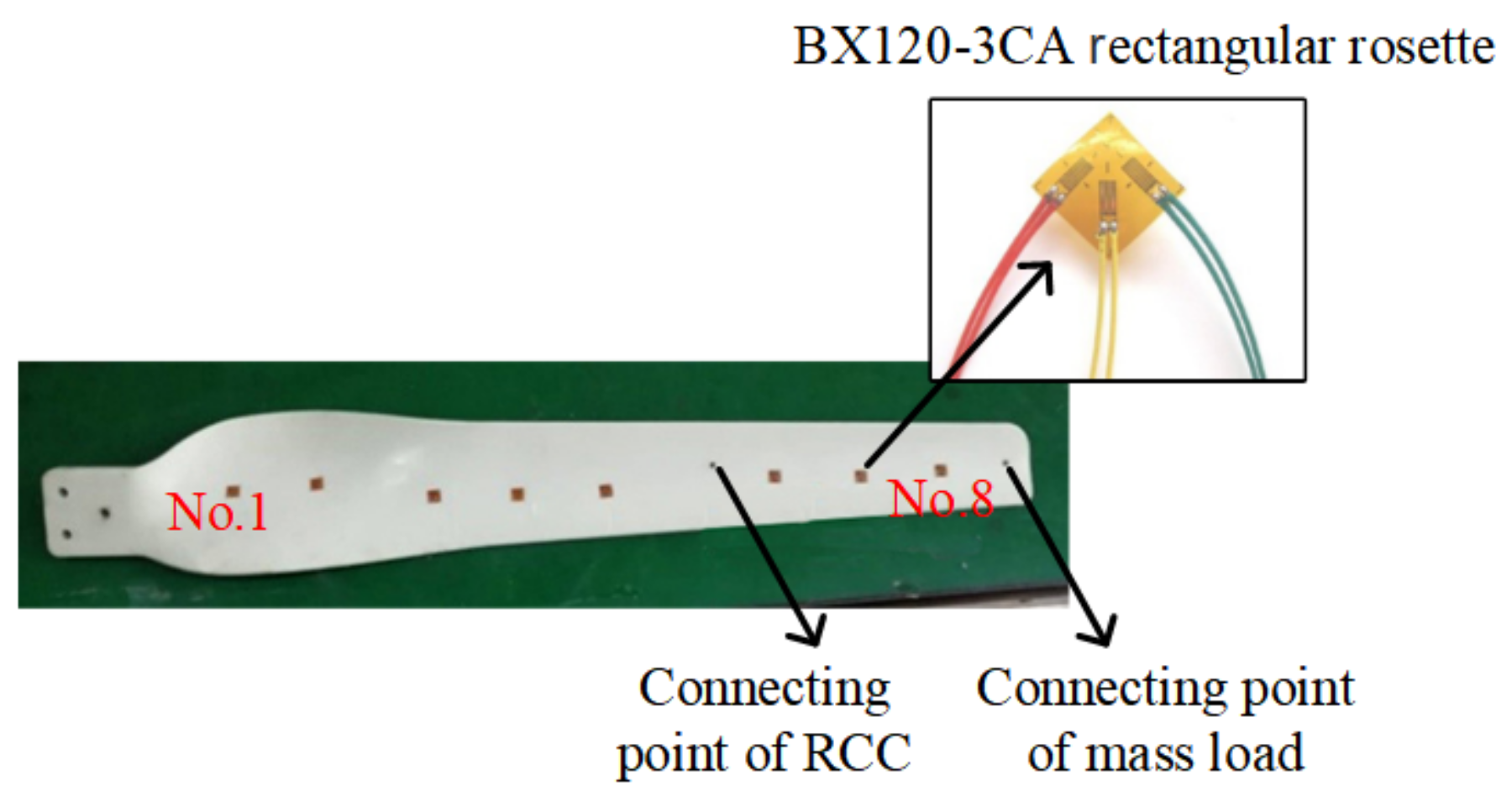
5.1. Test Description
5.2. Load Reduction Effect Discussion
6. Conclusions
Author Contributions
Funding
Institutional Review Board Statement
Informed Consent Statement
Conflicts of Interest
Nomenclature
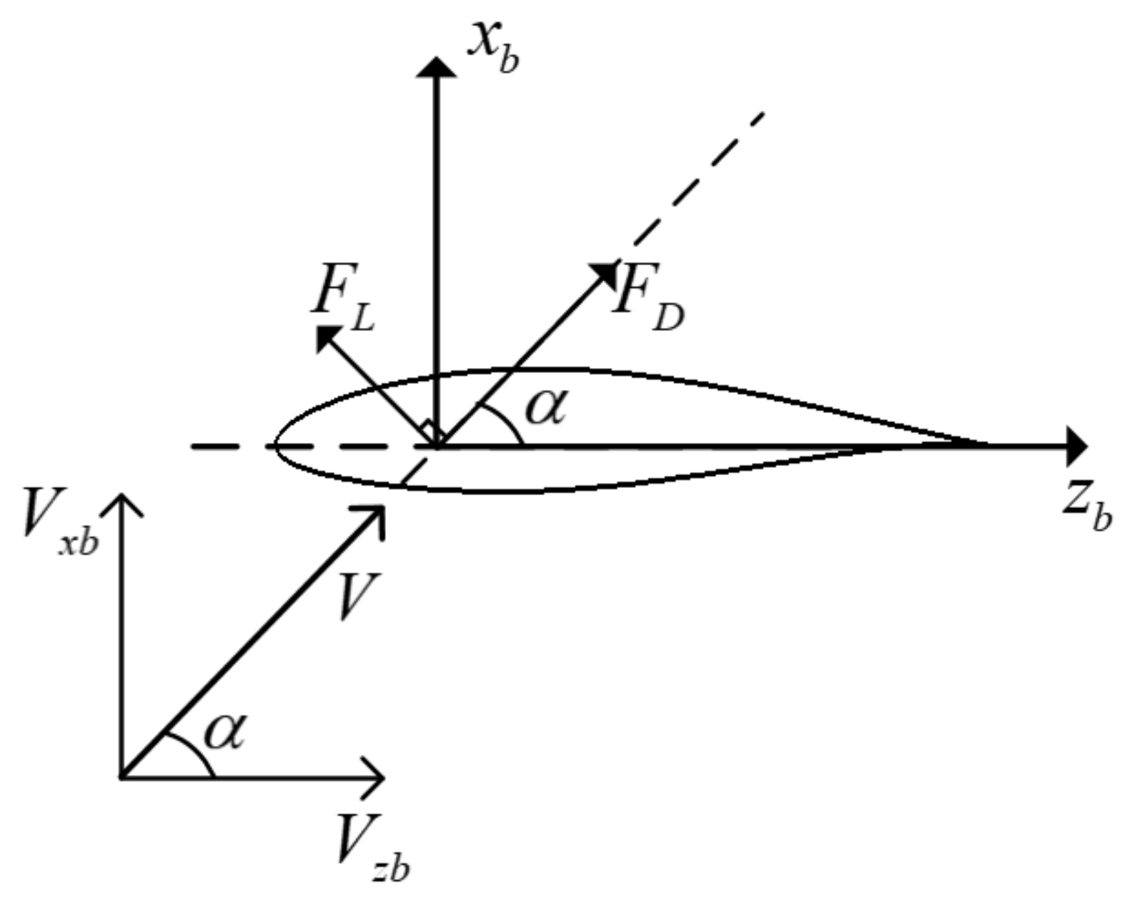
| Angle of attack () | Distributed wind load (N) | ||
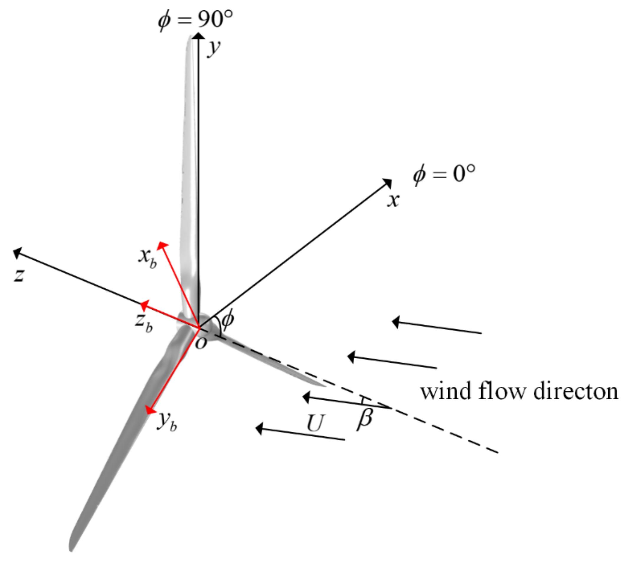
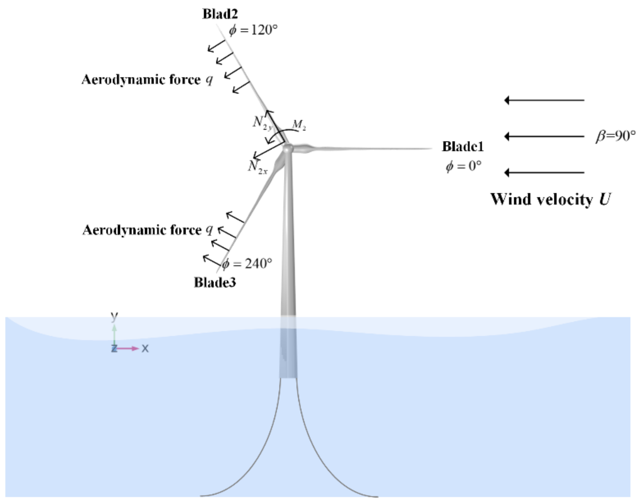
| Wind direction () | Distributed force (N) | ||
| Blade parking angle () | T | Tension force (N) | |
| Relative wind velocity () | stress () | ||
| Chord length (m) | Young’s modulus () | ||
| L | Blade length (m) | Strain in the axis direction | |
| Deflection of blade (m) | Strain with an angle of 45° to the horizontal axis | ||
| Length of RCC (m) | Average strain at measuring point i before applying RCC | ||
| Elongation of RCC (m) | Average strain at measuring point i after applying RCC | ||
| Bending section coefficient () |
References
- Tu, Q.; Liu, Z.; Li, B.; Mo, J. Achieving grid parity of offshore wind power in China–A comparative analysis among different provinces. Comput. Ind. Eng. 2021, 162, 107715. [Google Scholar] [CrossRef]
- GWEC. GWEC, Global Wind Report Annual Market Update 2021; Global Wind Energy Council: Brussels, Belgium, 2021. [Google Scholar]
- Enevoldsen, P.; Jacobson, M.Z. Data investigation of installed and output power densities of onshore and offshore wind turbines worldwide. Energy Sustain. Dev. 2021, 60, 40–51. [Google Scholar] [CrossRef]
- GWEC. GWEC, Global Wind Report Annual Market Update 2022; Global Wind Energy Council: Brussels, Belgium, 2022. [Google Scholar]
- Stewart, G.M.; Lackner, M.A. The impact of passive tuned mass dampers and wind–wave misalignment on offshore wind turbine loads. Eng. Struct. 2014, 73, 54–61. [Google Scholar] [CrossRef]
- He, R.; Pan, L. New Optimization Method of Multiple Tuned Mass Dampers Installed on Offshore Wind Turbines for Seismic Response Control. In Proceedings of the 32nd International Ocean and Polar Engineering Conference, Shanghai, China, 20 October 2021. [Google Scholar]
- Chen, C.-H.; Su, N.-J. Global Trends and Characteristics of Offshore Wind Farm Research over the Past Three Decades: A Bibliometric Analysis. J. Mar. Sci. Eng. 2022, 10, 1339. [Google Scholar] [CrossRef]
- Meng, H.; Jin, D.; Li, L.; Liu, Y. Analytical and numerical study on centrifugal stiffening effect for large rotating wind turbine blade based on NREL 5 MW and WindPACT 1.5 MW models. Renew. Energy 2022, 183, 321–329. [Google Scholar] [CrossRef]
- Ashuri, T.; Martins, J.R.R.A.; Zaaijer, M.B.; van Kuik, G.A.M.; van Bussel, G.J.W. Aeroservoelastic design definition of a 20MW common research wind turbine model. Wind Energy 2016, 19, 2071–2087. [Google Scholar] [CrossRef]
- Chen, X. Experimental investigation on structural collapse of a large composite wind turbine blade under combined bending and torsion. Compos. Struct. 2017, 160, 435–445. [Google Scholar] [CrossRef]
- Gasch, R.; Twele, J. Scaling wind turbines and rules of similarity. In Wind Power Plants: Fundamentals, Design, Construction and Operation; Gasch, R., Twele, J., Eds.; Springer: Berlin/Heidelberg, Germany, 2012; pp. 257–271. [Google Scholar] [CrossRef]
- Chen, X.; Xu, J.Z. Structural failure analysis of wind turbines impacted by super typhoon Usagi. Eng. Fail. Anal. 2016, 60, 391–404. [Google Scholar] [CrossRef]
- Chou, J.-S.; Chiu, C.-K.; Huang, I.-K.; Chi, K.-N. Failure analysis of wind turbine blade under critical wind loads. Eng. Fail. Anal. 2013, 27, 99–118. [Google Scholar] [CrossRef]
- Chen, C.P.; Kam, T.Y. Failure Analysis of Small Composite Sandwich Turbine Blade Subjected to Extreme Wind Load. Procedia Eng. 2011, 14, 1973–1981. [Google Scholar] [CrossRef][Green Version]
- Lee, H.G.; Kang, M.G.; Park, J. Fatigue failure of a composite wind turbine blade at its root end. Compos. Struct. 2015, 133, 878–885. [Google Scholar] [CrossRef]
- Zhang, X.; Wang, M.; Wang, Y.; Liu, Y. Research on Failure of Offshore Wind Turbine Tower in Typhoon. In Proceedings of the OCEANS—MTS/IEEE Kobe Techno-Oceans, Kobe, Japan, 28–31 May 2018; pp. 1–4. [Google Scholar]
- Bossanyi, E.A. Individual Blade Pitch Control for Load Reduction. Wind Energy 2003, 6, 119–128. [Google Scholar] [CrossRef]
- Stubkier, S.; Pedersen, H.C.; Markussen, K. Hydraulic soft yaw system load reduction and prototype results. In Proceedings of the EWEA Annual Event, Vienna, Austria, 4–7 February 2013. [Google Scholar]
- Kim, E.; Manuel, L. Hurricane-Induced Loads on Offshore Wind Turbines with Considerations for Nacelle Yaw and Blade Pitch Control. Wind Eng. 2014, 38, 413–423. [Google Scholar] [CrossRef]
- Bakhshi, R.; Sandborn, P. The Effect of Yaw Error on the Reliability of Wind Turbine Blades. In Proceedings of the ASME 2016 10th International Conference on Energy Sustainability collocated with the ASME 2016 Power Conference and the ASME 2016 14th International Conference on Fuel Cell Science, Engineering and Technology, Charlotte, NC, USA, 26–30 June 2016. [Google Scholar]
- Chen, X.; Li, C.; Xu, J. Failure investigation on a coastal wind farm damaged by super typhoon: A forensic engineering study. J. Wind Eng. Ind. Aerodyn. 2015, 147, 132–142. [Google Scholar] [CrossRef]
- Wang, J.; Chen, Z. Analysis of risks and measures on the blade damage of offshore wind turbine during strong typhoons—Enlightenment from Red Bay wind farm. Eng. Sci. 2010, 12, 32–34. [Google Scholar]
- Dai, J.; Hu, W.; Yang, X.; Yang, S. Modeling and investigation of load and motion characteristics of offshore floating wind turbines. Ocean Eng. 2018, 159, 187–200. [Google Scholar] [CrossRef]
- Lian, J.; Jia, Y.; Wang, H.; Liu, F. Numerical Study of the Aerodynamic Loads on Offshore Wind Turbines under Typhoon with Full Wind Direction. Energies 2016, 9, 613. [Google Scholar] [CrossRef]
- Lanzafame, R.; Messina, M. Fluid dynamics wind turbine design: Critical analysis, optimization and application of BEM theory. Renew. Energy 2007, 32, 2291–2305. [Google Scholar] [CrossRef]
- Hansen, M.O.L. Aerodynamics of Wind Turbines, 2nd ed.; Earthscan: London, UK, 2008. [Google Scholar]
- Dal Monte, A.; De Betta, S.; Raciti Castelli, M.; Benini, E. Proposal for a coupled aerodynamic–structural wind turbine blade optimization. Compos. Struct. 2017, 159, 144–156. [Google Scholar] [CrossRef]
- Wang, M.; Han, F.; Wu, Q. A steel cable connection component for wind turbine blade under mechanical braking state. 2016. [Google Scholar]
- Gere, J.M. Mechanics of Materials, 7th ed.; Mechanics of Materials: Amsterdam, The Netherlands, 2009. [Google Scholar]
- Resor, B.R. Definition of a 5MW/61.5 m Wind Turbine Blade Reference Model; Sandia National Lab.(SNL-NM): Albuquerque, NM, USA, 2013. [Google Scholar]
- Cox, K.; Echtermeyer, A. Structural Design and Analysis of a 10MW Wind Turbine Blade. Energy Procedia 2012, 24, 194–201. [Google Scholar] [CrossRef]
- Finnegan, W.; Jiang, Y.; Dumergue, N.; Davies, P.; Goggins, J. Investigation and Validation of Numerical Models for Composite Wind Turbine Blades. J. Mar. Sci. Eng. 2021, 9, 525. [Google Scholar] [CrossRef]
- Jiang, P.; Nan, R.-D.; Qian, L.; Yue, Y.-L. Studying solutions for the fatigue of the FAST cable-net structure caused by the process of changing shape. Res. Astron. Astrophys. 2015, 15, 1758. [Google Scholar] [CrossRef]
- Zhou, H.F.; Dou, H.Y.; Qin, L.Z.; Chen, Y.; Ni, Y.Q.; Ko, J.M. A review of full-scale structural testing of wind turbine blades. Renew. Sustain. Energy Rev. 2014, 33, 177–187. [Google Scholar] [CrossRef]
- Babawarun, T.; Ho, W.H.; Ngwangwa, H. Stress validation of finite element model of a small-scale wind turbine blade. J. Energy S. Afr. 2019, 30, 87–97. [Google Scholar] [CrossRef]


| Section Number | Distance to Blade Root/m | Chord Length/m | Twist Angle/° | AIRFOIL TYPE |
|---|---|---|---|---|
| s1 | 0 | 3.20 | 13.308 | Cylinder |
| s2 | 1.36 | 3.54 | 13.308 | Cylinder |
| s3 | 4.1 | 3.85 | 13.308 | Cylinder |
| s4 | 6.83 | 4.17 | 13.308 | DU40_A17 |
| … | … | … | … | … |
| s9 | 26.25 | 3.75 | 6.544 | DU25_A17 |
| s10 | 30.75 | 3.50 | 5.361 | DU21_A17 |
| … | … | … | … | … |
| s18 | 60.13 | 1.40 | 0.370 | NACA64_A17 |
| s19 | 61.5 | 0.70 | 0.106 | NACA64_A17 |
| Material Parameters | Young’s Modulus | Density | Poisson’s Ratio |
|---|---|---|---|
| RCC | 7800 | 0.28 |
| Section Number | Distance from Section to Blade Root /m | Equivalent Resultant Force /N | ||
|---|---|---|---|---|
| Blade 1 | Blade 2 | Blade 3 | ||
| S4 | 10.25 | 13,981.31 | 10,485.98 | 10,485.98 |
| S5 | 14.35 | 14,396.55 | 10,797.41 | 10,797.41 |
| S6 | 18.45 | 13,796.18 | 10,347.13 | 10,347.13 |
| S7 | 22.55 | 13,163.37 | 9872.53 | 9872.53 |
| S8 | 26.65 | 12,413.66 | 9310.24 | 9310.24 |
| S9 | 30.75 | 11,611.28 | 8708.46 | 8708.46 |
| S10 | 34.85 | 11,185.51 | 8389.13 | 8389.13 |
| S11 | 38.95 | 10,399.77 | 7799.83 | 7799.83 |
| S12 | 43.05 | 9620.90 | 7215.67 | 7215.67 |
| S13 | 47.15 | 8834.61 | 6625.96 | 6625.96 |
| S14 | 51.25 | 8048.31 | 6036.24 | 6036.24 |
| S15 | 54.67 | 7393.07 | 5544.80 | 5544.80 |
| S16 | 57.4 | 6667.51 | 5000.63 | 5000.63 |
| S17 | 60.13 | 4474.84 | 3356.13 | 3356.13 |
| S18 | 61.5 | 2237.42 | 1678.06 | 1678.06 |
| Blade Type | Blade 1 without RCC | Blade 2 without RCC | Blade 3 without RCC | |||
|---|---|---|---|---|---|---|
| Tip displacement /m | 7.04 | 5.13 | 6.78 | 1.49 | 6.74 | 2.61 |
| Average Strain | Without Reinforcing Cable Component | With Reinforcing Cable Component | B% |
|---|---|---|---|
| Measuring point 1 | 178.16 | 34.45 | 80.7% |
| Measuring point 2 | 176.26 | 47.59 | 73.0% |
| Measuring point 3 | 349.32 | 132.72 | 62.0% |
| Measuring point 4 | 221.06 | 91.13 | 58.8% |
| Measuring point 5 | 160.90 | 89.14 | 44.6% |
| Measuring point 6 | 161.55 | 167.46 | −3.7% |
| Measuring point 7 | 177.03 | 156.31 | 11.7% |
| Measuring point 8 | 97.30 | 105.77 | −8.7% |
Publisher’s Note: MDPI stays neutral with regard to jurisdictional claims in published maps and institutional affiliations. |
© 2022 by the authors. Licensee MDPI, Basel, Switzerland. This article is an open access article distributed under the terms and conditions of the Creative Commons Attribution (CC BY) license (https://creativecommons.org/licenses/by/4.0/).
Share and Cite
Fu, X.; Sheng, M. Research on Structural Failure Analysis and Strengthening Design of Offshore Wind Turbine Blades. J. Mar. Sci. Eng. 2022, 10, 1661. https://doi.org/10.3390/jmse10111661
Fu X, Sheng M. Research on Structural Failure Analysis and Strengthening Design of Offshore Wind Turbine Blades. Journal of Marine Science and Engineering. 2022; 10(11):1661. https://doi.org/10.3390/jmse10111661
Chicago/Turabian StyleFu, Xiaohan, and Meiping Sheng. 2022. "Research on Structural Failure Analysis and Strengthening Design of Offshore Wind Turbine Blades" Journal of Marine Science and Engineering 10, no. 11: 1661. https://doi.org/10.3390/jmse10111661
APA StyleFu, X., & Sheng, M. (2022). Research on Structural Failure Analysis and Strengthening Design of Offshore Wind Turbine Blades. Journal of Marine Science and Engineering, 10(11), 1661. https://doi.org/10.3390/jmse10111661