Article

Influence of Hydraulic PTO Parameters on Power Capture and Motion Response of a Floating Wind-Wave Hybrid System

1
Institute of Marine Science and Technology, Shandong University, Qingdao 266200, China
2
Key Laboratory of High Efficiency and Clean Mechanical Manufacture, Ministry of Education, Jinan 250061, China
3
Shenzhen Research Institute, Shandong University, Shenzhen 518057, China
4
School of Mechanical Engineering, Shandong University, Jinan 250061, China
*
Authors to whom correspondence should be addressed.
J. Mar. Sci. Eng. 2022, 10(11), 1660; https://doi.org/10.3390/jmse10111660
Submission received: 6 October 2022 / Revised: 26 October 2022 / Accepted: 31 October 2022 / Published: 4 November 2022
(This article belongs to the Special Issue Hybrid Systems for Marine Energy 2023)

Abstract

:
Hybrid systems that integrate wave energy converters (WECs) with floating offshore wind turbines (FOWTs) are considered to be key equipment to deeply exploit marine renewable energy. The power take-off (PTO) system is an important component of the hybrid system, whose parameters also have a significant impact on the hybrid system’s performance. In this paper, a wind-wave hybrid system using hydraulic PTO systems is proposed. A numerical simulation framework based on the linear wave theory and basic equations of hydraulic components is built and verified. The influence of six critical hydraulic parameters on the wave energy capture and motion response performance of the hybrid system is investigated. Specifically, the parameters of piston area, motor displacement, and equivalent generator damping affect the performance of the hybrid system similar to changing the damping term of the PTO system. The parameters of the initial gas volume and the pre-charged pressure of the accumulator affect the wave power capture only for short wave periods, while the motion response of the hybrid system increases with the increase of these two parameters. The parameter of orifice area of the throttle valve affects the performance of the hybrid system slightly only when it is small. The optimal value of partial hydraulic parameters and their corresponding peak performance are also discussed.

1. Introduction

As the world’s energy needs grow rapidly, fossil fuels are being used in excess, causing serious environmental and ecological problems [1,2,3]. Renewable energies, which have the benefits of low carbon and environmental friendliness, have been promoted as an alternative solution [4]. Over the past decades, with the continuous exploration of the sea, the huge potential of marine renewable energies has been gradually recognized [5,6]. A large number of projects to develop marine renewable energies such as offshore wind, wave and tidal have been launched in coastal areas [7,8,9]. For early built projects, most were located in shallow waters, and the energy conversion devices were usually fixed with monopile or jackets. Recently, with the further development of deep-sea areas, floating platforms have become the necessary infrastructure to carry larger energy conversion devices [10]. One problem that arises is the construction of floating platforms is usually costly, which has a negative impact on the economics of the project. At the same time, floating platforms are prone to having large motion responses under wave action, which reduces power production as well as being detrimental for structural safety.
To tackle this dilemma, the concept of co-development with multiple marine renewable energies has been proposed, and the co-development of offshore wind energy and wave energy is regarded as one of the most potent combinations [11]. Wave has a significant correlation with wind, so areas suitable for wind energy development are mostly also rich in wave energy resources. Meanwhile, wave energy is more stable than wind energy. The output stability of wind energy can be improved with the complement of wave energy. Furthermore, the FOWT can also be used as a carrier of WECs, which is expected to share infrastructure and maintenance costs. The wave absorption of WECs can also reduce the impact of waves on FOWTs [12]. Due to the above advantages, the floating wind-wave hybrid system has attracted great interest from scholars in related fields, and various wind-wave hybrid systems have been proposed [13,14].
One of the key issues in the design and research of floating wind-wave hybrid systems is to increase the additional energy output as well as reduce the motion of the floating platform. The PTO system, as one of the most essential subsystems of WEC, also plays an important role in this issue. On the one hand, the wave energy captured by WECs must undergo the secondary conversion of the PTO system to convert into electricity, so the PTO system will directly determine the output power of WECs. On the other hand, WECs will transfer force and torque to the FOWT via the PTO system, which means that the characteristics of PTO system will also affect the hybrid system’s motion. The necessity of investigating the PTO system of the hybrid system is thus evident.
Among the relevant studies conducted in recent years, most have involved the effect of PTO parameters on energy conversion and motion response of the hybrid system, for example in [15,16,17,18,19,20,21,22,23,24,25]. From the above literature, one can find that most scholars have simplified the PTO system in their numerical simulation and model experiment. Specifically speaking, in numerical studies [15,16,17], a linear damping coefficient is used to represent the PTO system of the wind-wave hybrid system. For studies focusing on the PTO control strategies such as [18], the damping and stiffness coefficients were used to express three different control strategies. As for experimental studies, PTO systems are instead simulated using physical friction, such as friction dampers and springs [19,20,21], Airflow orifice (OWC type WEC) [22,23], and air cylinders [24,25].
However, it is worth noting that for large-scale devices such as wind-wave hybrid systems, the mainstream form of PTO system is hydraulic, which has high efficiency and is well suited for low frequency and high-power density waves [26,27,28,29]. Hydraulic PTO systems usually consist of several hydraulic components, and different component parameters will result in complex energy conversion and force reaction characteristics [30,31,32]. To make the study of PTO systems in wind-wave hybrid systems more relevant, a detailed investigation of the effects of different hydraulic parameters is necessary. However, only a few studies have discussed this issue, e.g., [33,34]. In [33], a set of small water-hydraulic system was used to simulate the PTO system. However, several key components such as accumulator and throttle valve were ignored. Meanwhile, in [34], the authors designed a hydraulic transformer-based PTO system for a wind-wave hybrid system and investigated the effect of different hydraulic parameters on the efficiency and stability of the wave energy output. Unfortunately, the authors did not apply this practical hydraulic system to their experimental model, and the effect of different hydraulic PTO parameters on the performance of the hybrid system is still unclear. Due to the current situation, this paper considers a floating hybrid wind-wave system with hydraulic PTO systems. The effects of critical hydraulic PTO parameters on the performance of the system will be investigated. The results are expected to be a useful reference for the hydraulic PTO system design of the hybrid system.
The remainder of this paper is organized as follows: Section 2 presents the design of the proposed hybrid system; Section 3 describes the mathematical principles of numerical modeling; Section 4 presents the detail of the simulation framework and parameter setup; Section 5 presents the simulation results and discussion; and finally, the conclusions and future work are discussed in Section 6.

2. Hybrid System Description

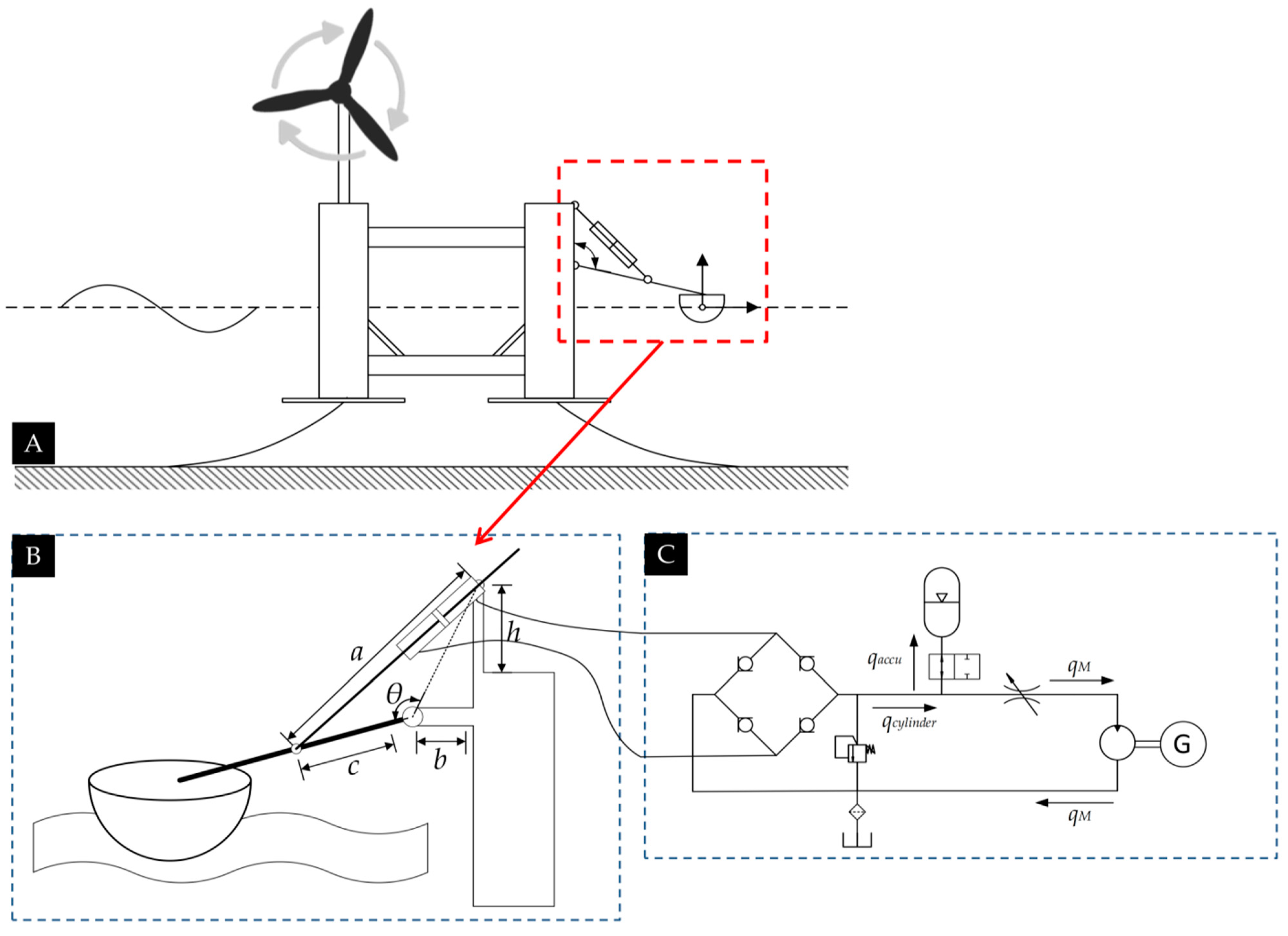
The overall schematic of the proposed wind-wave hybrid system is shown in Figure 1, and the principle schematic diagram is shown in Figure 2. The hybrid system consists of a semi-submersible floating platform, a wind turbine, and 9 point-absorbing WECs. These point-absorbing WECs are positioned along the edge of the floating platform and connected to the horizontal support beam through rocker arm mechanisms. The hydraulic actuators are hinged between the rocker arm and the floating platform and can easily extend out and draw back under the drive of the rocker arm. Each hydraulic actuator is connected to the hydraulic PTO system mounted on the floating platform via several pipelines.
With the action of sea waves, the floating platform with large mass moves slightly, while the buoys fluctuate greatly. The wave energy is captured by the buoys and converted into mechanical energy. Constrained by the rocker arm, the buoy rotates around the hinge joint along with the rocker arm and drives the hydraulic actuator to stretch and draw. The hydraulic oil in the chamber is compressed along with the telescoping motion of the hydraulic actuator, converting mechanical energy into fluid pressure energy. Following this, the high-pressure hydraulic oil will flow into the hydraulic PTO system. Under the action of these hydraulic components, the hydraulic oil will be rectified and stabilized. After that, the oil flows into the hydraulic motor to drive it to rotate. The fluid pressure energy of the high-pressure hydraulic oil eventually converts into electrical energy by the electric generator connected to the hydraulic motor.
Compared with the scheme of installing heave buoys on a floating platform proposed in [15], rocker WECs were selected for the hybrid system proposed in this section. The long rocker arm of the WEC will be able to increase the rotational torque transmitted by the buoy to the floating platform, which is expected to further increase the effectiveness of reducing the motion response of the hybrid system. Also compared with reference [18] which also integrated rocker-arm WECs with a semi-submergible FOWT, the hybrid system proposed in this section cleverly utilizes the beam of the floating platform to carry more WECs. Moreover, this integration form also provides significant savings in the construction cost of WECs while facilitating retrofitting.

3. Mathematical Principles of Numerical Modeling

3.1. Simplifying Assumptions

To facilitate the mathematical modeling of the hybrid system, some assumptions are made below:
  • The performance of the hybrid system will only be studied under normal sea conditions, so the linear wave theory and potential flow theory are applicable;
  • The inclination of the floating platform generated by the aerodynamic forces on the wind turbine has been corrected by the ballast system, so no additional aerodynamic forces will be considered in mathematical modeling;
  • The rocker arms are seen as rigid rods whose own weight is negligible;
  • The hydraulic oil in the hydraulic PTO system is considered incompressible, and the leakage and loss can be ignored.

3.2. Equation of Motion of a Floating Body

Based on the above-mentioned assumptions, the hybrid system can be regarded as several connected floating bodies, and the governing equation of each floating body in the time domain can be expressed as:
M ε ¨ ( t ) = F ex + F r + F hs + F c + F PTO
where M is the mass matrix of the floating body, ε ( t ) is the column vector of the displacement of the floating body, F ex , F r , F hs   are the column vector of wave excitation force, wave radiation force, and hydrostatic restoring force, respectively. F c is the column vector of the connecting force, and F PTO is the column vector of the reaction force of the hydraulic PTO system. For a floating body with six degrees of freedom, M is a matrix of size 6 × 6, and ε(t),   F ex   ,   F r ,   F hs ,   F c   ,   F PTO   are column vectors of size 6 × 1.
The hydrodynamic force acting on the floating body can be calculated according to Cummins’ theory [35], so Equation (1) can be written as:
[ M + A ( ) ] ε · · ( t ) + 0 t B ( t τ ) ε · ( t )   d τ + K hs ε ( t ) = h ( t τ )   η ( τ )   d τ + F c   + F PTO
where A ( ) is the limiting added mass matrix at an infinite frequency, B ( t τ ) is the matrix of radiation impulse response function (IRF),   K hs   is the matrix of hydrostatic restoring force coefficient, h ( t τ )   is the IRF matrix of wave excitation force, and η ( τ )   is the undisturbed wave elevation at the center point of the floating body.
The coefficients of   K hs   and   η ( τ )   depend on the geometry and draft of the floating body, and the coefficients of A ( ) ,   B ( t τ )   , and   h ( t τ )   can be obtained by solving the radiation and diffraction problems based on the linear potential flow theory. Commercial software ANSYS/AQWA based on BEM (Boundary Element Method) will be used to calculate these hydrodynamic coefficients in this paper.

3.3. Mechanical Connections

Since the mass and deformation of the rocker arm have been ignored in simplifying assumptions, the rocker arm can be regarded as an ideal articulated constraint, so the connecting force F c     on floating bodies can be solved by following equations:
F c ( t ) = D T f c ( t )
D ε ( t ) = 0
where D is the displacement constraint matrix, which can be obtained according to the type of connection and the position of the connection point, and f c is the column vector of local connection force.

3.4. Hydraulic Reaction Force

As shown in Figure 2A, both ends of the hydraulic actuator are hinged, so the reaction force of the hydraulic PTO system can be equivalent to a resistance torque. Here we take the rocker arm in the oxy plane as an example. The reaction force of the hydraulic PTO system acting on the floating body can be written as:
F PTO = T PTO   ·   L arm
T PTO = F act 1 a 2 + c 2 b 2 h 2 2 ac · c
where T PTO is the equivalent resistance torque, L arm is the length of rocker arm, F act is the reaction thrust force of the hydraulic actuator, and a, b, c, h are the geometric dimensions of the rocker arm. The reaction thrust force F act can be written as:
F act = (   p t p b ) · A p
A p = π ( d p 2 d r 2 ) 4
where A p   is the area of piston, p t   and p b   are the fluid pressure of the upper and bottom chamber, respectively, and d p   and d r are the diameter of piston and rod, respectively.
Assuming that the piston is moving upward, the oil in the upper chamber will be pressed. Since the oil tank is connected to the atmosphere, the value of p b   will be taken as 0. The value of p t is equal to the pressure of the accumulator, which can be calculated by following equations:
q act = z act · A p
q accu = q act   q M
p · accu p pre = κ q accu V g 0
p accu = p t
where z act   is the displacement of the piston, q act   is the oil flow from the upper chamber,     q accu is the oil flow into the accumulator,   q M   is the oil flow through the hydraulic motor,   p accu   is the fluid pressure of the accumulator,   p pre   is the pre-charged gas pressure of the accumulator,   κ is the gas adiabatic index, and V g 0 is the initial gas volume of the accumulator.
The throttle valve is used to control the flow of oil into the hydraulic motor. Here, the orifice form of the throttle valve is set as thin-walled type, and the pressure–flow relationship of the orifice can be written as:
q M = C d A v 2 ( p M   p accu ) ρ o
where C d is the flow coefficient, A v is the flow area of the valve orifice, and p M is the oil pressure on the swash plate of the hydraulic motor. The speed and torque of the hydraulic motor can be calculated by following equations:
q M = φ D M ω M
J t ω · M = φ D M ( p M p tank ) T G
where   φ   is the swash plate angle coefficient, D M is the displacement of the hydraulic motor, ω M is the rotation speed of the hydraulic motor, J t is the total moment of inertia of hydraulic motor and electric generator, p tank is the pressure of oil tank which is taken as 0, and T G is the resistance torque of the generator. The value of T G can be calculated by the following equation when the load of the electric generator is pure resistance:
T G = B G · ω M
where   B G     is the electromagnetic damping coefficient of the generator.
By combining Equations (7)–(16) to eliminate, the reaction force of the hydraulic actuator F act   can be expressed as a function of the displacement of the piston z act . According to the geometric layout shown in Figure 2A, the value of z act   can be calculated by following equations:
z act = a c 2 + b 2 + h 2 2 c b 2 + h 2 cos ( θ β )  
  θ = cos 1 c 2 + b 2 + h 2 a 2 2 c b 2 + h 2  
  β = cos 1 2 L 2 x x 0 2 y y 0 2 2 L  
where   θ is the initially included angle between the rocker arm and horizontal direction, β is the rotation angle of the rocker arm, x and y   are the real-time coordinates of the connection point between buoy and rocker arm,   x 0 and y 0 are the initial coordinates of the connection point between buoy and rocker arm. Since the coordinates of the connection point between buoy and rocker arm can be converted from the column vector of the displacement of floating body ε , the PTO system reaction force F PTO can finally be expressed as a function of the motion of buoys, which we write as F PTO ( ε ) .

3.5. Equation of Motion of the Hybrid System

By substituting F PTO ( ε )   into Equation (2) and extending Equation (2) to the case of N floating bodies, the governing equation of the hybrid system can be written as:
M 1 0 0 M N + A 11 ( ) A 1 N ( ) A N 1 ( ) A N N ( ) · ε ¨ 1 ε ¨ N + 0 t B N t τ ε 1 ˙ ε N ˙ d τ + K hs 1 0 0 K hsN · ε 1 ε N = h N ( t τ ) η 1 η N   d τ + F c 1 F cN + F PTO 1 ( ε ) F PTON ( ε )  
where the subscript i of M,   ε ( t ) , K hs ,   η ,   F c   ,   F PTO   represents the relevant parameters of the i-th floating body, the subscript i, j of A ( ) represents the additional mass of the j-th floating body generated on the i-th floating body, and the matrix of IRF B N   and h N   will also be expanded into the size of 6n × 6n. The operational situation of the hybrid system can be obtained by solving Equation (20) using numerical methods such as Newton–Euler and 4th-order Runge–Kutta.

3.6. Performance Evaluation Indicators

In order to quantitatively measure the performance of the hybrid system, the average capture width ratio (CWR) and pitch motion response amplitude operator (RAO) are selected as the wave energy capture and motion response performance evaluation indicators of the hybrid system, respectively. The value of these two performance evaluation indicators can be calculated by following equations:
CWR = P average P wave D  
RAO = α H
where P average is the average power of each WEC in the hybrid system,   P wave is the energy of wave per unit width,   D is the water surface area of buoys, α is the pitch angle of the floating platform when it reaches a stable motion state, and H is the wave height. The values of P average and P wave can be calculated by following equations:
P average = m = 1 n P WECm n P WEC = 1 T simu   0 T simu 2 π ω M ( t ) T G ( t ) dt  
P wave = ρ g 2 H 2 T 32 π · tan h ( kh ) 1 + 2 kh sin h ( 2 kh )
where P WEC is the power output of the wave energy converter via hydraulic PTO system, and the subscript m of P WEC   represents the power output of the m-th set of wave energy convertors,   T simu is the simulation duration, n is the number of WECs,   k is the wave number, and   h   is the water depth.

4. Numerical Simulation Setups

4.1. Simulation Framework

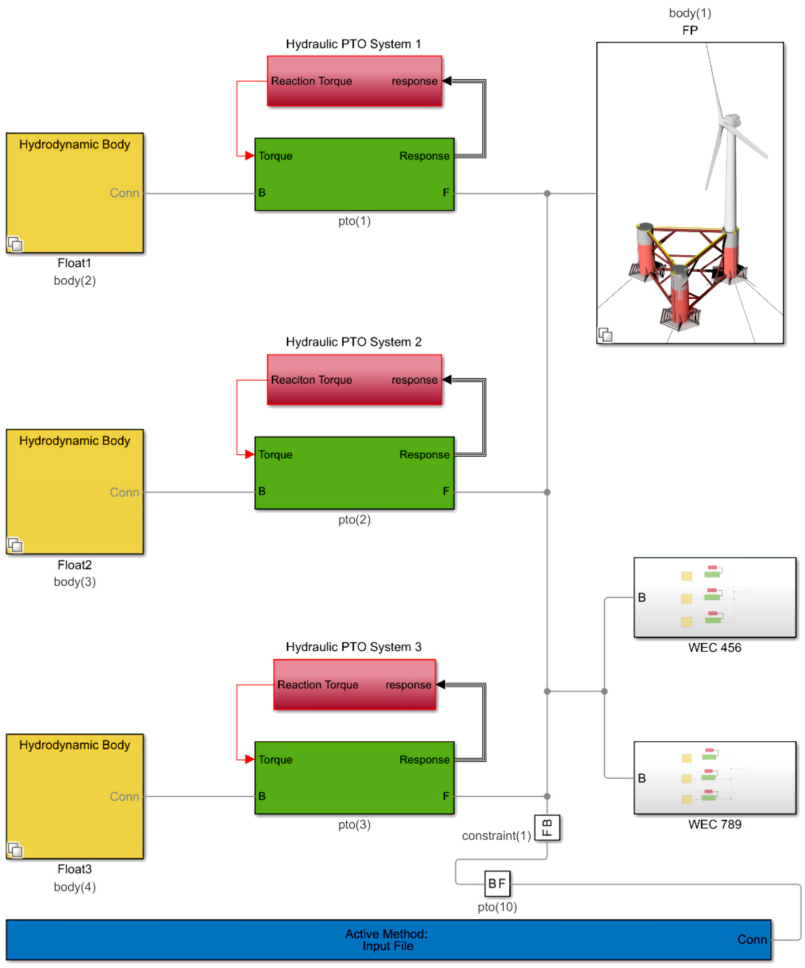
The open-source code WEC-sim will be used for the numerical simulation in this paper. Developed by National Renewable Energy Laboratory (NREL) and Sandia National Laboratory (SNL), the WEC-sim toolbox can simulate various kinds of wave energy converters intuitively [36]. The numerical simulation framework built in MATLAB/Simulink using WEC-sim toolbox is shown as Figure 3. Components of the hybrid system are built with different modules in the simulation framework. Floating bodies including floating platforms and buoys are termed as hydrodynamic bodies and marked in yellow squares in Figure 3. For brevity, only three sets of WECs at one side of the floating platform are presented, and the other six sets of WECs will be abbreviated into subsystems. Rocker arms are termed as rotary constraints which are marked in green squares. The hydraulic PTO system is built with basic Simulink modules as shown in Figure 4 and integrated into subsystems. The angular velocity of the rotation constraint is taken as the input of the PTO subsystem, and the reaction resistance torque will be output back to the rotation constraint. The PTO subsystems are marked in red squares in Figure 3.
To highlight the influence of the hydraulic PTO system on the motion response of the hybrid system, the mooring system is simplified as a motion constraint in the horizontal direction, which is implemented in Simulink using the constraint module as shown in Figure 3. Therefore, the platform will only be able to move along the heave direction or rotate during the simulation. Meanwhile, due to the geometric symmetry of the hybrid system, the effect of different incoming wave directions on the hybrid system will also be ignored, and the wave incidence of 0 degrees will be considered for all cases.

4.2. Parameters Setup

4.2.1. Sea States

The parameters of three sea states are given here, as shown in Table 1. The operating sea state is the sea state in which the hybrid system normally operates, which refers to the design sea state of the Winfloat FOWT [37]. The default value of the hybrid system will also be determined based on the operational sea states. The verification sea state is used to verify the accuracy of the simulation framework built in Simulink, so commonly used irregular wave parameters are selected. The regulating sea state is used to study the performance of the hybrid system in a wide range of sea states, so its value will be adjusted appropriately based on the operational sea state.

4.2.2. Floating Platform and Wave Energy Convertors

A semi-submersible floating platform with three columns is selected for the proposed hybrid system, and its dimensional and inertial parameters are also referred to the Windfloat [37]. As for WECs, each set of WEC consists of a hemispherical buoy and a rocker arm, and the main parameters are designed to achieve 10 kW power generation for each set under operational sea states.
The specific parameters of the floating platform and wave energy converters are shown in Table 2. Note that the thickness of the heave damping plate has been appropriately increased to facilitate the boundary element mesh generation, and the weight of the turbine tower has already been included in the inertia of the floating platform through the equivalent mass method proposed in [38].

4.2.3. Hydraulic PTO system

As the schematic diagram of the hydraulic PTO system presented in Figure 2C, the main components of the hydraulic PTO system include double-acting hydraulic actuator, check valve, accumulator, throttle valve, hydraulic motor, and electric generator. The default values of these hydraulic parameters are also designed to achieve 10 kW power under the operational sea condition for each set of WEC, which are given in Table 3.
In addition, since case studies of the influence of different hydraulic component parameters will be carried out in the following sections, the selection of key hydraulic component parameters and their variation range and steps will be carried out. Here, six critical parameters which have a significant effect on the performance of the hybrid system are selected as the research objects, and their value ranges will be determined based on the default values and the availability of hydraulic components in the market. A summary of the parameters of case studies is provided in Table 4.

4.2.4. Simulation Solver Settings

In the next sections, the operation of the wind-wave hybrid system will be solved in Simulink using the simulation framework. The relevant parameters of the solver are shown in Table 5.

5. Result and Discussion

5.1. Numerical Framework Validation

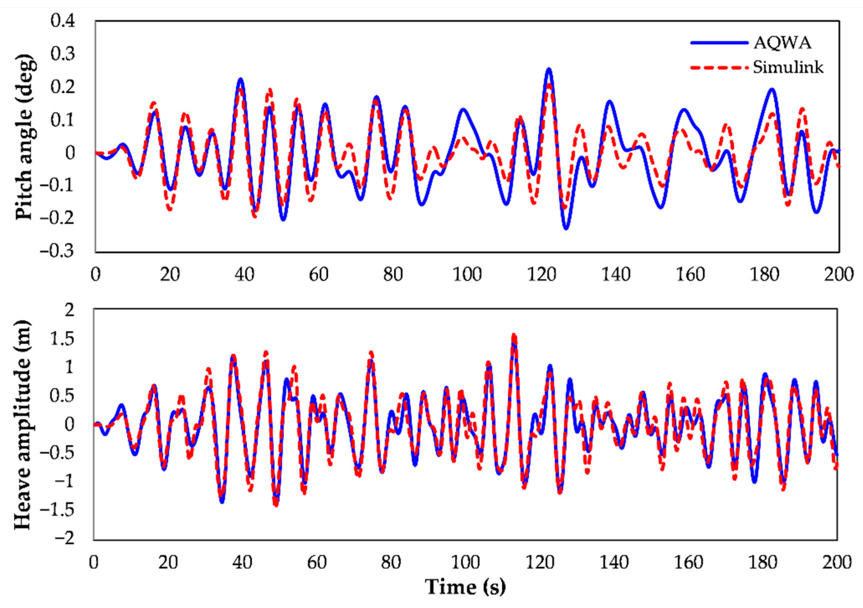
The calculation results of the hydrodynamics and the hydraulic subsystem will be verified in this paper. The time domain solver of the commercial software ANSYS/AQWA is chosen for hydrodynamic verification. The Design Modeler module is used to establish the same three-dimensional model and the Hydrodynamic Diffraction module is used to calculate the hydrodynamic coefficient. The rocker arm is represented by a hinged connection in the AQWA interface. Since hydraulic system cannot be realized in AQWA, the resistance damping will not be added at the hinge point both for AQWA and the simulation framework in Simulink. The verification will be carried out under the validation sea state mentioned in Table 1. It can be seen from Figure 5 that the calculation results of the simulation framework in Simulink have a good fit with AQWA’s embedded time domain solver, which means that the simulation framework in Simulink is accurate enough in hydrodynamic calculation.
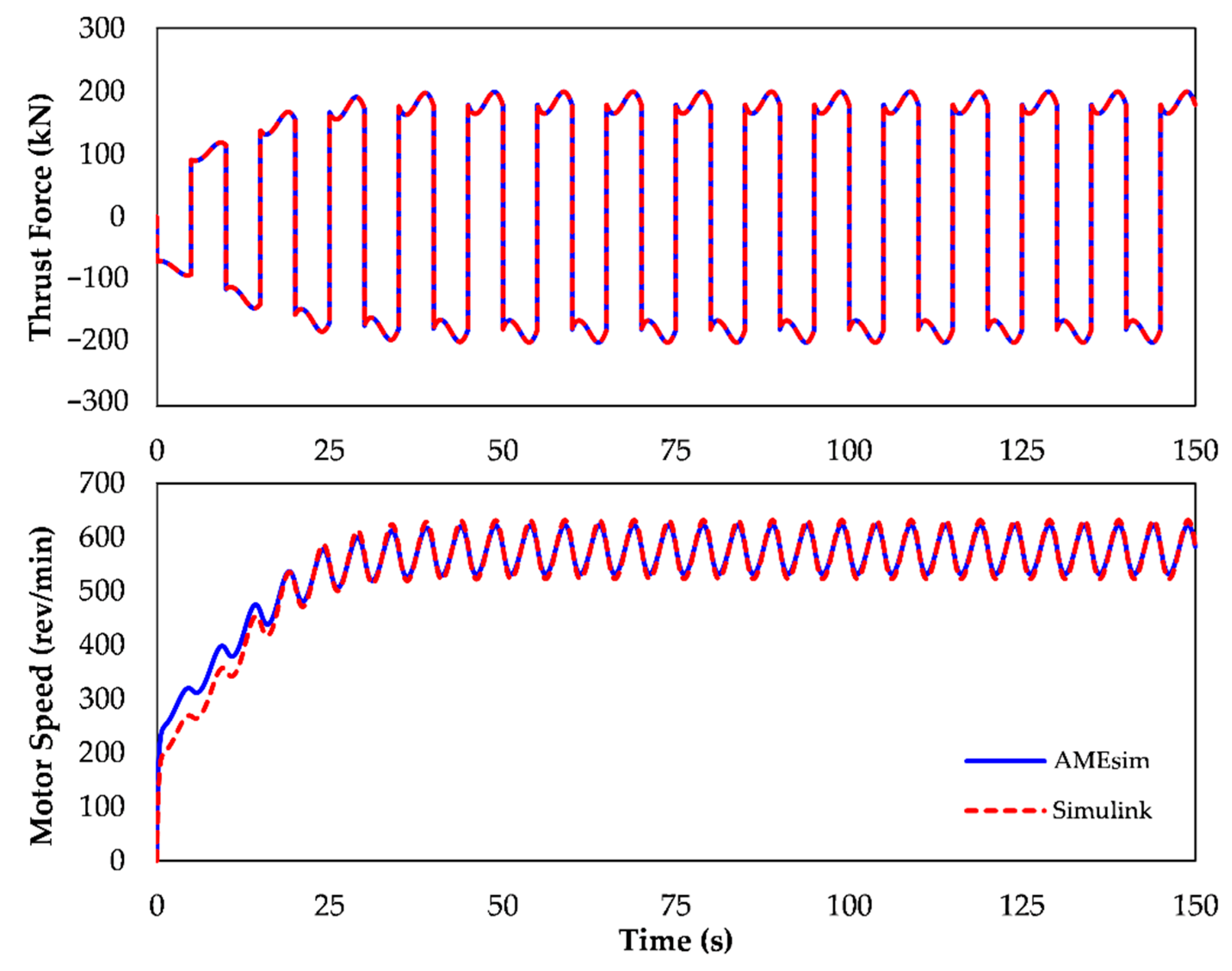
As for the hydraulic PTO subsystem, the widely recognized commercial software SIEMENS/AMEsim is chosen for verification. The simulation framework based on the schematic diagram in Figure 2C is built in AMESim. The check valve, accumulator, throttle valve, and hydraulic motor are modeled with sub-models in HYD library, and the hydraulic cylinder is modeled with sub-models in HCD library. The verification will be carried out by applying a same sinusoidal reciprocating speed on the piston rod of AMESim and Simulink. It can be seen from Figure 6 that the reaction force of the hydraulic actuator and the speed of the hydraulic motor in AMESim and Simulink are almost identical, which strongly demonstrates the accuracy of the hydraulic PTO system built in Simulink.

5.2. Influence Analysis of Hydraulic PTO Parameters

5.2.1. Influence of Piston Area

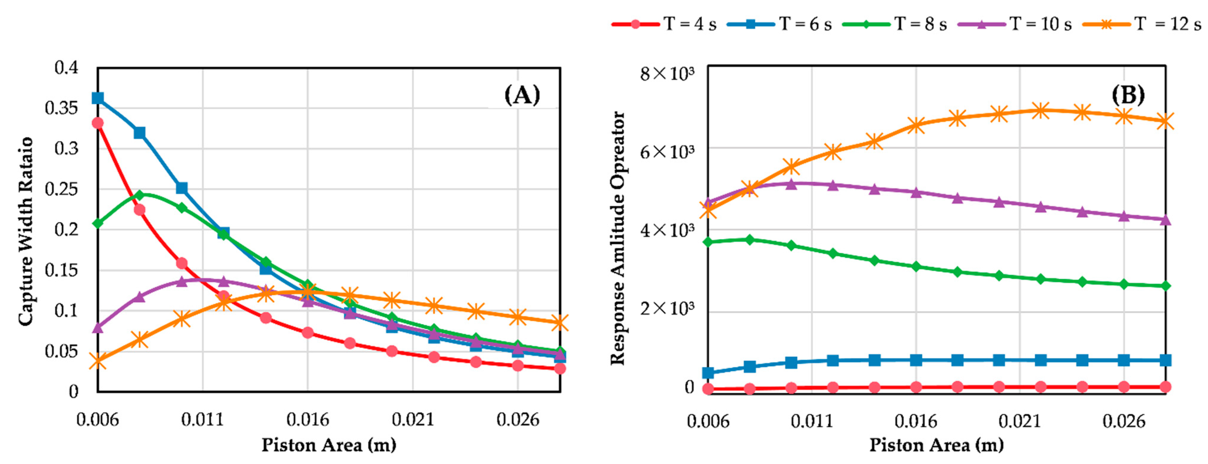
From Equation (5), it can be found that the reaction force of the hydraulic PTO system is related to the piston area A P , which means the value of A P will directly affect the reaction force, and thus the motion response performance of the hybrid system. On the other hand, the piston area can change the flow rate of the hydraulic oil, which affects the value of output power. Therefore, the influence of A P on the performance of the hybrid system will be discussed in this section.
Figure 7 shows the variation of CWR and pitch RAO with A P under different wave states. It is obvious in Figure 7A that the CWR of the hybrid system has a trend of increasing and then decreasing with the increase of A P , which indicates the existence of an optimal piston area to achieve the highest energy capture efficiency. Although the CWR seems to decrease monotonically under wave states of T = 4 s and T = 6 s, it might be caused by the optimal piston area under these two wave states are smaller than the value range. Moreover, the CWR under different wave periods changes more significantly for smaller A P , and will finally decrease to a same smaller value range with the continuous increase of A P . As for the pitch motion response, it can be obtained from Figure 7B that the pitch RAO also shows a trend of first increasing and then decreasing with the increase of the A P .
Further study will be carried out to investigate the variation of the optimal piston area and their corresponding performances under different wave states. Here, the piston area to achieve the highest CWR is denoted by A P power , and the corresponding peak CWR is denoted by CWR*. The piston area to achieve the lowest pitch RAO is denoted by A P motion , and the corresponding pitch RAO is denoted by RAO*.
Figure 8 shows the variation of the optimal piston areas and the corresponding performance indicators under different wave states. It can be found from Figure 8A that A P power raises with the increase of wave period, and each A P power   under different wave heights has little difference. This differs considerably from the variation of A P motion   shown in Figure 8B. Specifically speaking, when the wave period is small (T = 4–6 s), a smaller piston area can allow the hybrid system to achieve maximum wave energy capture efficiency with minimal motion response. However, as the wave period increases, the most efficient wave energy capture and the minimal motion response cannot be achieved simultaneously with a certain piston area.
In terms of the corresponding CWR*, it can be seen from Figure 8B that the overall variation trend of CWR* under different wave heights has little difference. It increases first and then decreases with the increase of wave period. The CWR* reaches the maximum value at the wave period T = 6 s, which is speculated to be the resonance of WEC under this wave period. Another observed phenomenon is that the CWR* under smaller wave heights is much higher than that under larger wave heights, indicating that the hybrid system will achieve higher energy capture efficiency under smaller wave heights. The corresponding RAO* reaches the maximum value at the wave period T = 11 s. Moreover, it can also be learned that for a certain wave height, the closer the wave period is to the natural frequency of the hybrid system, the more obvious the influence of A P on the RAO* is.
The above variation law indicates that the effect of changing the piston area is similar to changing the damping term of the PTO system. Moreover, one can also find that the optimal energy capture efficiency and motion response can be achieved simultaneously only for small wave periods, and in most cases, both cannot be achieved at the same time. Considering that the piston area in a real hydraulic PTO system is usually unchangeable, the piston area is more suitable for multi-objective optimization design based on deployment sea states rather than as a means of real-time variable damping adjustment.

5.2.2. Influence of Initial Gas Volume of Accumulator

Accumulators play a role in absorbing pressure and flow pulsations in hydraulic systems, so their parameters have a significant impact on the efficiency and smoothness of the energy output. In addition, the effect of the accumulator will also change the reaction force characteristics of the hydraulic PTO system, which in turn affects the motion response of the hybrid system. As a key component of the hydraulic PTO system, the effect of the accumulator parameters on the performance of the hybrid system needs to be carefully investigated.
The variation of CWR and pitch RAO with initial gas volume of accumulator V g 0 is shown in Figure 9. As can be seen in Figure 9A, the value of CWR shows a variation of first increases slightly with increasing V g 0 and then tends to a stable value for most sea states. The exception is the value of CWR under wave periods T = 4 s which has an opposite trend before tending to a stable value with increasing V g 0 . As for Figure 9B, it can be found that the pitch RAO increases with the increase of V g 0 under all wave states. The larger the wave period is, the more obvious the pitch RAO increases. Moreover, the effect of V g 0 on the pitch RAO of the hybrid system is more significant when V g 0 is smaller, which is similar to its effect on CWR.
The reason for the above variation law is speculated as follows. The pre-charged gas in the accumulator acts like a spring. Small V g 0 will lead to poor buffer performance, resulting in excessive hydraulic resistance force acting on WEC and thereby reducing the energy capture efficiency. With V g 0 increasing continually until the buffering performance is good enough, the further increase of V g 0 will no longer improve the wave energy capture efficiency. That explains the reason why the value CWR shows a trend of first increasing and then tending to a stable value as V g 0 increases. On the other hand, larger V g 0 will also lead to larger inertia of the accumulator, thus reducing the buffer capacity to short-pressure pulsation. As a result, the CWR decreased with the increase of V g 0 under the sea state with a small wave period. As for the influence of V g 0 on the motion response of the floating platform, the increased V g 0 reduces the pressure fluctuation of the hydraulic PTO system, which is equivalent to reducing the stiffness of the spring term of the PTO system. The hydrostatic restoring torque generated by the WEC buoy will be absorbed by the spring term when the floating platform tilts, resulting in an increase of the motion amplitude.
Based on the analysis above, the following conclusions can be drawn for the selection of the value of V g 0 . In order to ensure wave energy conversion efficiency, the value of V g 0 should not be too small. However, too large V g 0 not only has little effect on improving the wave energy conversion efficiency but also intensifies the motion of the hybrid system and increases the cost. Therefore, the value of V g 0 which enables the CWR to reach the stable value is considered to be a reasonable choice. For the hybrid system proposed in this paper, the reasonable V g 0 should be 40–60 L.

5.2.3. Influence of Pre-Charged Pressure of Accumulator

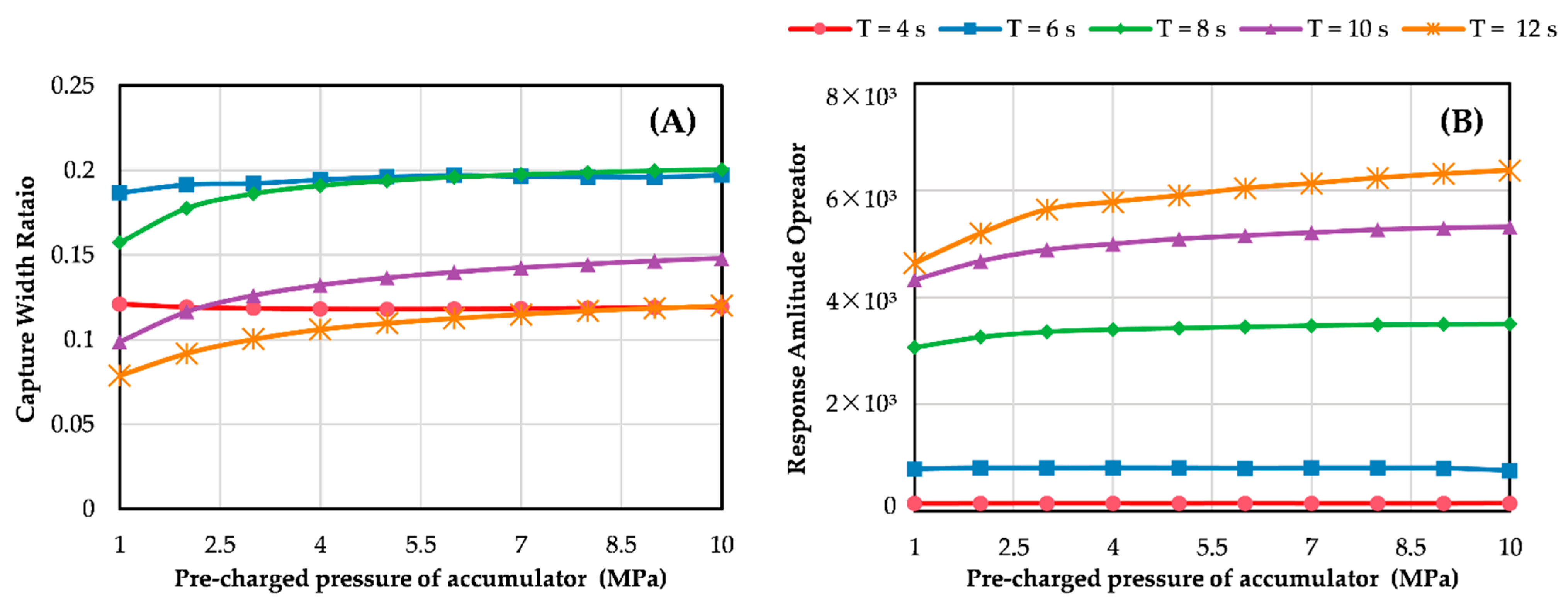
Figure 10 presents the variation of initial gas volume of accumulator P pre on the CWR and pitch RAO under different wave states. It can be drawn from Figure 10A that with the increase of P pre , the CWR firstly increases slightly and then keep constant after P pre reaches a certain value for most wave states, while for smaller wave periods, the CWR firstly decreases and then tends to a stable value. As for Figure 10B, it can be found that the RAO increases with the increase of P pre for all wave states, and the effect of P pre will be more significant with the increase of the wave period.
The effect of P pre is quite similar to the effect of V g 0 . Specifically speaking, small pre-charged pressure of the accumulator will influence the wave energy capture efficiency, while large P pre appears to make little effect. Therefore, we can draw the same conclusion that the value of P pre which enables the CWR to reach a stable value be a reasonable choice. For the proposed hybrid system, taking the value of P pre as 5.5–7.0 MPa will be able to meet the requirements.

5.2.4. Influence of Orifice Size of Throat Valve

The throttle valve is set at the inlet of the hydraulic motor to control the flow rate of hydraulic oil. Together with the swash plate angle adjusting mechanism inside the hydraulic motor, a volume–flow speed control circuit is constituted to adjust the speed of the hydraulic motor. In this paper, the throttle valve port is modeled mathematically in the form of thin-walled holes, so the size of orifice will be set as the investigation subject.
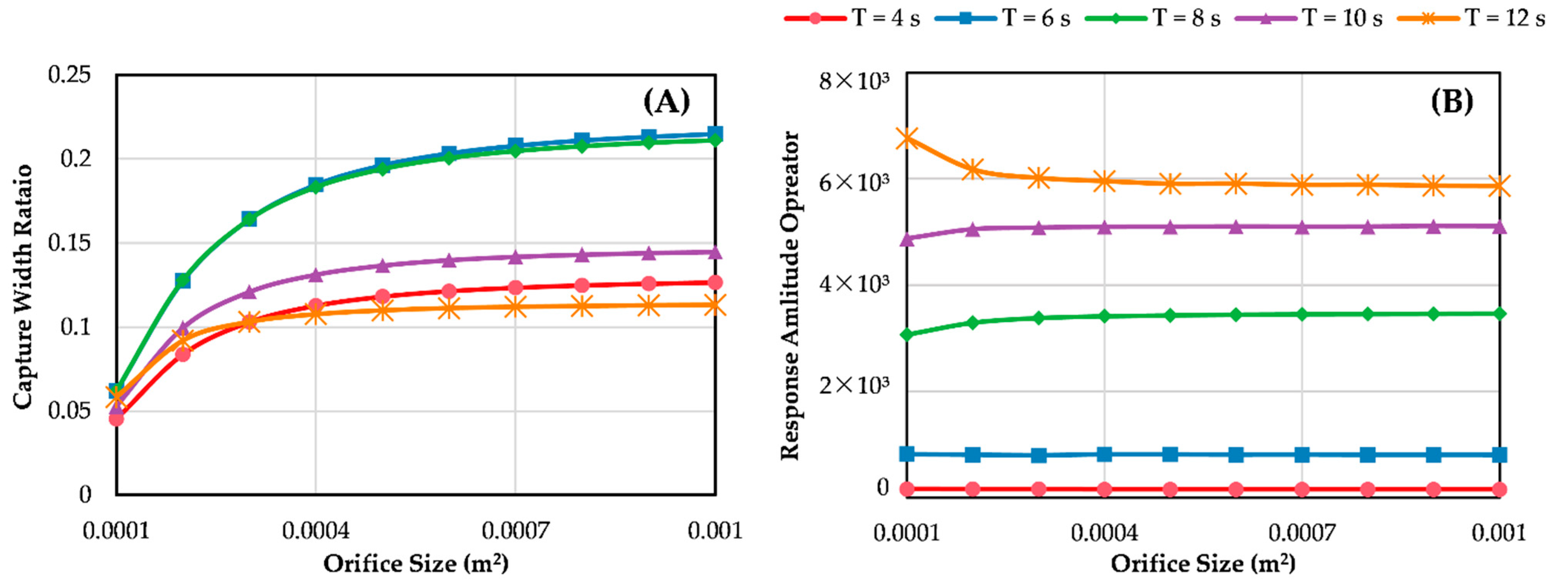
Figure 11 presents the variation of CWR and pitch RAO with the orifice size of throat valve A v . It can be found from Figure 11A that the CWR of the hybrid system shows an increasing trend with the increase of A v , while the change rate of CWR gradually decreases with the increase of A v . As for Figure 11B, the value of A v has different effects on RAO under different wave states. For wave states with smaller periods (T = 4–6 s), the value of A v has almost no effect on RAO. As the period increases (T = 8–10 s), the RAO firstly increases slightly and then becomes stable with the increase of A v . However, as the wave period increases further (T = 12 s), the RAO will decrease slightly and then stabilizes with the increase of A v .
The following analysis and conclusions can be drawn from the above. Under the condition that other parameters remain constant, a smaller valve port flow area will produce greater pressure loss at the valve port, which reduces the wave energy conversion efficiency. At the same time, it can be seen from Equation (13) that the differential pressure term is under the root sign. This is the reason why the change rate of the CWR in Figure 11A decreases with the increase of the flow area. As for the influence on the platform RAO, the value of A v only slightly affects the motion response of the hybrid system when it is small, and the overall degree of influence is not obvious. In conclusion, the value of the orifice size has a more significant effect on the wave energy conversion, while it has almost no effect on the motion response of the hybrid system. Therefore, the throttle valve can be used to adjust the power output of the hydraulic PTO system, but not suitable to control the motion response of the hybrid system.

5.2.5. Influence of Displacement of Hydraulic Motor

The hydraulic motor controls the rotation speed by changing D M , which is called volumetric speed control. The displacement of hydraulic motor has a direct effect on the torque of the hydraulic motor, which in turn has an impact on power output and hydraulic reaction force. Therefore, it is necessary to explore the influence of the displacement of hydraulic motor on the performance of the hybrid system.
Figure 12 presents the variation of CWR and pitch RAO with the displacement of hydraulic motor D M . As can be seen from Figure 12A, the CWR decreases after reaching a peak with the increase of D M , which means that there is an optimal hydraulic motor displacement to get a maximum CWR. Although the CWR appears to be monotonically increasing with D M for wave periods of T = 4 s and T = 6 s, it is speculated due to the optimal hydraulic motor displacement values for these two wave states are larger than the exploration range. As for the effect on the pitch RAO, it can be seen from Figure 12B that D M has almost no effect on the RAO under wave states with short wave period (T = 4–6 s), while for wave states with medium wave period (T = 8–10 s), the RAO will show a trend of increase first and then stabilize, with a not obvious peak appears. As the wave period continues to increase (T = 12 s), the RAO will first increase slightly and then decrease with the increase of D M .
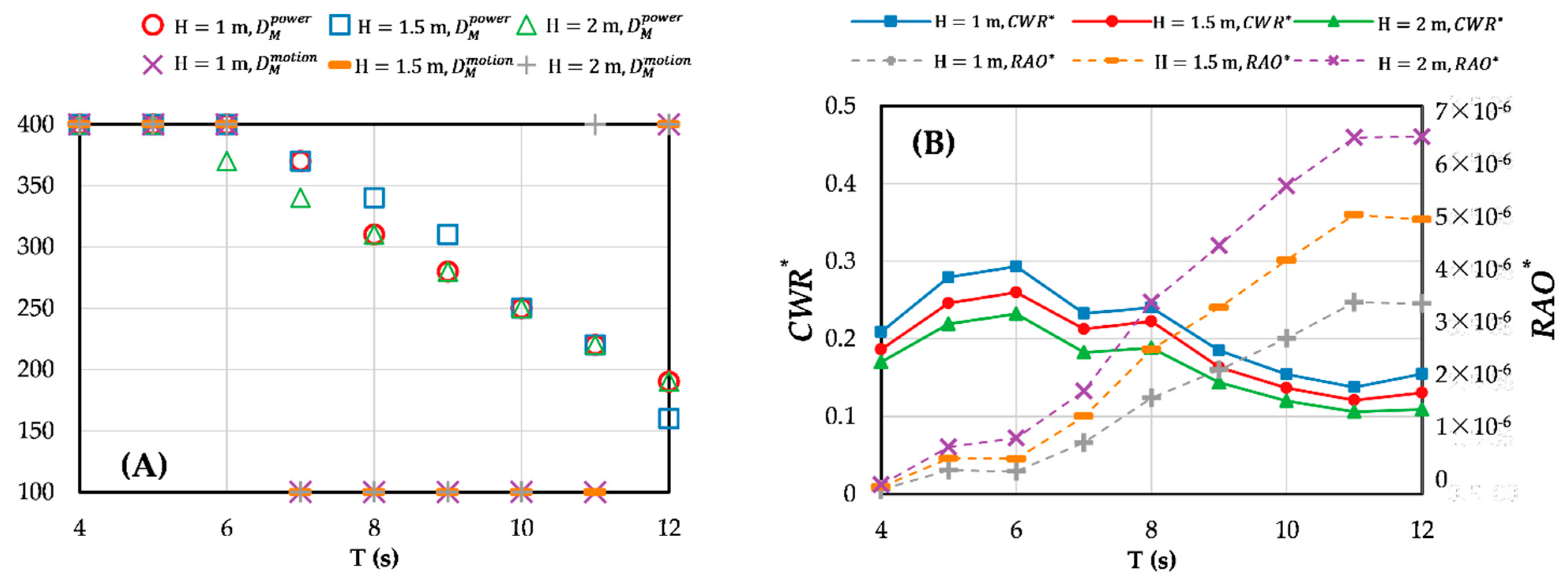
Further investigation will be carried out about the variation of the optimal displacement of hydraulic motor and their corresponding performance under different wave states. Here the displacement of hydraulic motor to achieve the peak CWR is denoted by D M   power , and the displacement of hydraulic motor to achieve the lowest RAO is denoted by D M   motion . The definitions of CWR * and RAO * are the same as in Section 4.2.1.
The variation of the optimal displacement of hydraulic motor and the corresponding performance indicators under different wave states is shown in Figure 13. As can be seen from Figure 13A, the value of D M   power and D M   motion under different wave heights shows little difference, indicating that the wave height hardly affects the value of optimal hydraulic motor displacement. In contrast, the wave period shows an obvious influence on the values of D M   power and D M   motion , where D M   power decreases with the increase of the wave period, and the variation law of D M   motion is more complicated. Specifically speaking, for wave states with small (T = 4–6 s) and large (T = 12 s) wave period, D M   motion takes the minimum value of the range, while for wave states with medium wave periods (T = 7–11 s), the maximum value will be taken. As for Figure 13B, the CWR * increases to a peak and then decreases with the increase of the wave period, while the RAO * has a continuing increase until reaches the maximum value. Moreover, for wave states with certain wave periods, a larger wave height will result in a smaller CWR * , but a larger RAO * .
The following is the analysis of the above results. Under the condition that the generator equivalent damping is maintained, the smaller the value of D M , the faster the rotation speed of the hydraulic motor, and accordingly, the higher oil pressure of the hydraulic system. Excessive oil pressure will make it difficult for the piston rod to move, which is equivalent to increasing the damping of the PTO system and thus reducing the wave energy conversion efficiency. In general, the influence principle of the displacement of the hydraulic motor is similar to that of the piston area. Both of them affect the performance of the hybrid system by changing the damping term of the PTO system. It is worth noting that the damping effect of the hydraulic system is inversely proportional to D M . This explains why Figure 13A shows an opposite variation law to that of Figure 9A. Considering that the displacement of hydraulic motor in the actual hydraulic PTO system can be easily adjusted, using D M as a means to control the performance of the hybrid system dynamically will be an effective and practical option.

5.2.6. Influence of Equivalent Damping Coefficient of the Generator

As the hydraulic motor drives the generator to rotate, the rotor of the generator rotates to cut the magnetic induction line, generating an electromagnetic resistance torque. The resistance torque is similar to the damping force, so the equivalent damping coefficient of the generator B G is used to characterize the electromagnetic resistance torque characteristics of the generator. The value of B G has a direct impact on the power output and also affects the oil pressure of the hydraulic system together with the displacement of the hydraulic motor. Therefore, it can be expected that the value of B G will have a crucial impact on the performance impact of the hybrid system, which will be investigated in depth in this section.
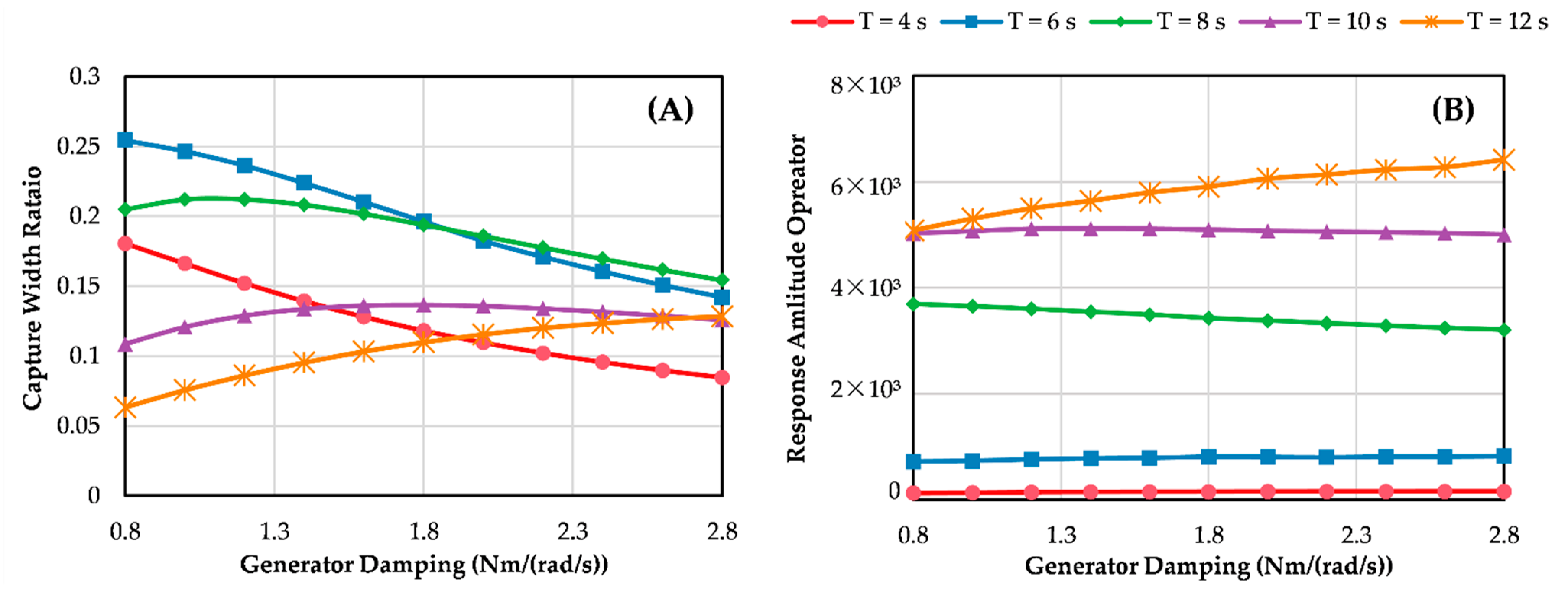
Figure 14 shows the variation of CWR and pitch RAO with B G under different wave states. It can be seen from Figure 14A that for wave states with small wave periods (T = 4–8 s), the CWR descends with the increase of B G , and the descending slope also decreases with the increase of the wave period. For wave states of T = 10 s, the CWR shows a variation law of increasing and then decreasing with the growth of B G , but the peak of CWR is not obvious. With the further increase of the wave period (T = 12 s), the CWR will increase monotonically. As for Figure 14B, it can be seen that for wave states with small wave period (T = 4–6 s), the value of B G has little effect on the RAO, and for wave states with medium wave period (T = 8–10 s), the RAO will decrease with the increase of B G . As the wave period continues to increase, the RAO will increase with the increase of B G .
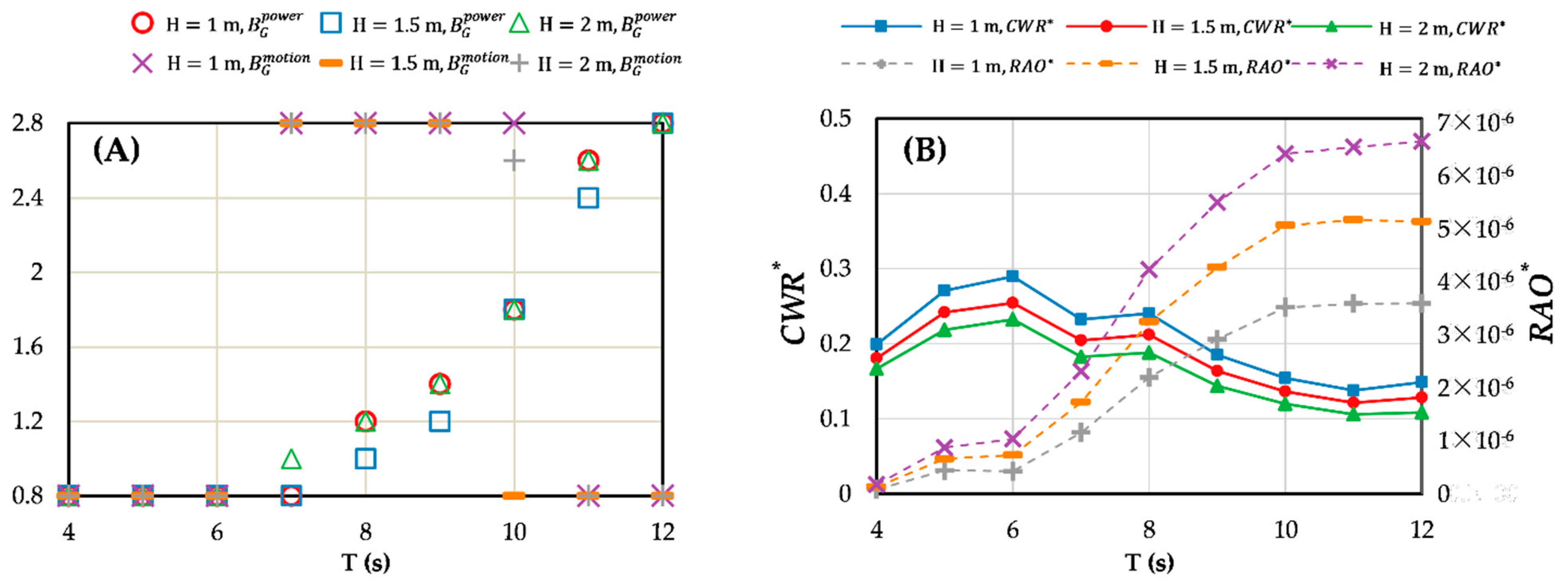
Further exploration will be carried out to investigate the variation law of the optimal equivalent damping coefficient of the generator and the corresponding performance of the hybrid system. Here the equivalent damping coefficient of the generator to achieve the peak CWR is denoted by B G   power , and the equivalent damping coefficient of the generator to achieve the lowest pitch RAO is denoted by B G   motion . The definitions of CWR * and RAO * are the same as in previous sections.
From Figure 15A, it can be found that the wave height has little effect on the value of B G   power and B G   motion , while the wave period shows a significant effect on the optimal equivalent damping coefficient of the generator. The value of B G   power   raises with the increasing wave period, and B G   motion shows a variation law similar to that of the piston area. Meanwhile, the variation trend shown in Figure 15B is also similar to that in Figure 7B, with the difference that the CWR * in Figure 15B shows a trend of first increasing and then stabilizing with the increase of wave period, and does not show a peak as in Figure 7B.
From the above analysis, we can find that the effect of B G is very similar to that of A P and D M , which affects the performance of the hybrid system by changing the damping characteristics of the hydraulic PTO system. However, the value of B G only has a limited effect on the performance of the hybrid system, which is not as significant as A P . Therefore, the equivalent damping coefficient of the generator will be better suited to cooperate with grid control to improve the quality of electrical output.

6. Conclusions

In this paper, a floating wind-wave hybrid system is proposed as the study object. The hydraulic PTO system of the WEC is mathematically modeled via equations of hydraulic components, and a MATLAB/Simulink-based simulation framework is built and verified. The influences of six critical hydraulic parameters on the energy capture and the motion response performance of the hybrid system are investigated under a wide range of wave states. The optimal value selections of some hydraulic parameters are also discussed in detail. From the investigation and analysis, the following conclusions can be drawn:
  • Three parameters, piston area, hydraulic motor displacement, and equivalent generator damping coefficient, have similar effects on the performance of the hybrid system by changing the damping terms of the PTO system. For a given wave state, all three parameters have corresponding optimal values that enable the hybrid system to achieve the optimal state of wave energy capture or motion response. However, the optimal energy capture efficiency and motion response can be achieved simultaneously only for small wave periods. For most sea states, both cannot be achieved at the same time. In addition, for the specified wave states with the same wave period, larger wave height reaches a smaller wave power capture width ratio and larger pitch response.
  • The parameters of the initial gas volume and the pre-charged pressure of the accumulator have almost the same effect. The values of these two parameters have a slight effect on the wave power capture width ratio, especially for large values. The pitch motion response of the hybrid system will increase with the increases of initial gas volume and the pre-charged pressure. The larger the wave period is, the more the pitch motion response increases.
  • The value of orifice size of the throttle valve has a significant effect on wave energy capture efficiency when it is small, while hardly affecting the motion response of the hybrid system. Therefore, the throttle valve will be suitable to be used as a method to control the power output of the hydraulic PTO system, rather than to adjust the motion response of the hybrid system.
The present study is expected to provide a useful reference for researchers and engineers in selecting and designing a wind-wave hybrid system equipped with a hydraulic PTO system. Meanwhile, it is worth noting that, in most cases, different performances’ optimum states of the hybrid systems cannot be achieved simultaneously. Thus, further studies such as multi-objective optimization of relevant parameters and design of dynamic control strategies for selected parameters are suggested.

Author Contributions

Conceptualization, Y.W.; formal analysis, S.H.; funding acquisition, Y.L.; investigation, S.H.; methodology, S.H.; project administration, Y.L.; resources, Y.L.; software, Y.W.; supervision, G.X.; writing—original draft, Y.W.; writing—review and editing, G.X. All authors have read and agreed to the published version of the manuscript.

Funding

This research was funded by Natural Science Foundation of Shandong Province (grant number ZR2021ZD23), Guangdong Basic and Applied Basic Research Foundation (grant number 2021A1515110687), and the National Natural Science Foundation of China (grant number 52171265).

Institutional Review Board Statement

Not applicable.

Informed Consent Statement

Not applicable.

Data Availability Statement

Not applicable.

Acknowledgments

The authors would like to thank Department of Science and Technology of Shandong Province, Department of Science and Technology of Guangdong Province and Ministry of Science and Technology of the People’s Republic of China for financial support for this research.

Conflicts of Interest

The authors declare no conflict of interest.

References

  1. Sorrell, S. Reducing energy demand: A review of issues, challenges and approaches. Renew. Sustain. Energy Rev. 2015, 47, 74–82. [Google Scholar] [CrossRef] [Green Version]
  2. Martins, F.; Felgueiras, C.; Smitkova, M.; Caetano, N. Analysis of fossil fuel energy consumption and environmental impacts in European countries. Energies 2019, 12, 964. [Google Scholar] [CrossRef] [Green Version]
  3. Höök, M.; Tang, X. Depletion of fossil fuels and anthropogenic climate change—A review. Energy Policy 2013, 52, 797–809. [Google Scholar] [CrossRef] [Green Version]
  4. Dincer, I. Renewable energy and sustainable development: A crucial review. Renew. Sustain. Energy Rev. 2000, 4, 157–175. [Google Scholar] [CrossRef]
  5. Melikoglu, M. Current status and future of ocean energy sources: A global review. Ocean. Eng. 2018, 148, 563–573. [Google Scholar] [CrossRef]
  6. Borthwick, A.G. Marine renewable energy seascape. Engineering 2016, 2, 69–78. [Google Scholar] [CrossRef] [Green Version]
  7. Wang, S.; Yuan, P.; Li, D.; Jiao, Y. An overview of ocean renewable energy in China. Renew. Sustain. Energy Rev. 2011, 15, 91–111. [Google Scholar] [CrossRef]
  8. Shadman, M.; Silva, C.; Faller, D.; Wu, Z.; de Freitas Assad, L.P.; Landau, L.; Levi, C.; Estefen, S.F. Ocean renewable energy potential, technology, and deployments: A case study of Brazil. Energies 2019, 12, 3658. [Google Scholar] [CrossRef] [Green Version]
  9. Magagna, D.; Uihlein, A. Ocean energy development in Europe: Current status and future perspectives. Int. J. Mar. Energy 2015, 11, 84–104. [Google Scholar] [CrossRef]
  10. Butterfield, S.; Musial, W.; Jonkman, J.; Sclavounos, P. Engineering Challenges for Floating Offshore Wind Turbines; National Renewable Energy Lab. (NREL): Golden, CO, USA, 2007. [Google Scholar]
  11. Guedes Soares, C.; Bhattacharjee, J.; Karmakar, D. Overview and prospects for development of wave and offshore wind energy. Brodogr. Teor. I Praksa Brodogr. I Pomor. Teh. 2014, 65, 87–109. [Google Scholar]
  12. Borg, M.; Collu, M.; Brennan, F.P. Use of a wave energy converter as a motion suppression device for floating wind turbines. Energy Procedia 2013, 35, 223–233. [Google Scholar] [CrossRef]
  13. Karimirad, M. Offshore Energy Structures: For Wind Power, Wave Energy and Hybrid Marine Platforms; Springer: Berlin/Heidelberg, Germany, 2014. [Google Scholar]
  14. Pérez-Collazo, C.; Greaves, D.; Iglesias, G. A review of combined wave and offshore wind energy. Renew. Sustain. Energy Rev. 2015, 42, 141–153. [Google Scholar] [CrossRef] [Green Version]
  15. Hu, J.; Zhou, B.; Vogel, C.; Liu, P.; Willden, R.; Sun, K.; Zang, J.; Geng, J.; Jin, P.; Cui, L. Optimal design and performance analysis of a hybrid system combing a floating wind platform and wave energy converters. Appl. Energy 2020, 269, 114998. [Google Scholar] [CrossRef]
  16. Michailides, C.; Luan, C.; Gao, Z.; Moan, T. Effect of flap type wave energy converters on the response of a semi-submersible wind turbine in operational conditions. In International Conference on Offshore Mechanics and Arctic Engineering; American Society of Mechanical Engineers: New York, NY, USA, 2014; V09BT09A014. [Google Scholar]
  17. Muliawan, M.J.; Karimirad, M.; Moan, T. Dynamic response and power performance of a combined spar-type floating wind turbine and coaxial floating wave energy converter. Renew. Energy 2013, 50, 47–57. [Google Scholar] [CrossRef]
  18. Si, Y.; Chen, Z.; Zeng, W.; Sun, J.; Zhang, D.; Ma, X.; Qian, P. The influence of power-take-off control on the dynamic response and power output of combined semi-submersible floating wind turbine and point-absorber wave energy converters. Ocean. Eng. 2021, 227, 108835. [Google Scholar] [CrossRef]
  19. Gao, Z.; Moan, T.; Wan, L.; Michailides, C. Comparative numerical and experimental study of two combined wind and wave energy concepts. J. Ocean. Eng. Sci. 2016, 1, 36–51. [Google Scholar] [CrossRef] [Green Version]
  20. Gaspar, J.F.; Kamarlouei, M.; Thiebaut, F.; Soares, C.G. Compensation of a hybrid platform dynamics using wave energy converters in different sea state conditions. Renew. Energy 2021, 177, 871–883. [Google Scholar] [CrossRef]
  21. Kamarlouei, M.; Gaspar, J.; Calvario, M.; Hallak, T.; Mendes, M.J.; Thiebaut, F.; Soares, C.G. Experimental analysis of wave energy converters concentrically attached on a floating offshore platform. Renew. Energy 2020, 152, 1171–1185. [Google Scholar] [CrossRef] [Green Version]
  22. Zhang, D.; Chen, Z.; Liu, X.; Sun, J.; Yu, H.; Zeng, W.; Ying, Y.; Sun, Y.; Cui, L.; Yang, S.; et al. A coupled numerical framework for hybrid floating offshore wind turbine and oscillating water column wave energy converters. Energy Convers. Manag. 2022, 267, 115933. [Google Scholar] [CrossRef]
  23. Perez-Collazo, C.; Pemberton, R.; Greaves, D.; Iglesias, G. Monopile-mounted wave energy converter for a hybrid wind-wave system. Energy Convers. Manag. 2019, 199, 111971. [Google Scholar] [CrossRef]
  24. Ren, N.; Ma, Z.; Shan, B.; Ning, D.; Ou, J. Experimental and numerical study of dynamic responses of a new combined TLP type floating wind turbine and a wave energy converter under operational conditions. Renew. Energy 2020, 151, 966–974. [Google Scholar] [CrossRef]
  25. Ma, Z.; Wang, S.; Wang, Y.; Ren, N.; Zhai, G. Experimental and numerical study on the multi-body coupling dynamic response of a novel serbuoys-tlp wind turbine. Ocean. Eng. 2019, 192, 106570. [Google Scholar] [CrossRef]
  26. Lin, Y.; Bao, J.; Liu, H.; Li, W.; Tu, L.; Zhang, D. Review of hydraulic transmission technologies for wave power generation. Renew. Sustain. Energy Rev. 2015, 50, 194–203. [Google Scholar] [CrossRef]
  27. Zhang, D.; Li, W.; Lin, Y.; Bao, J. An overview of hydraulic systems in wave energy application in China. Renew. Sustain. Energy Rev. 2012, 16, 4522–4526. [Google Scholar] [CrossRef]
  28. Jusoh, M.A.; Ibrahim, M.Z.; Daud, M.Z.; Albani, A.; Mohd Yusop, Z. Hydraulic power take-off concepts for wave energy conversion system: A review. Energies 2019, 12, 4510. [Google Scholar] [CrossRef] [Green Version]
  29. Gaspar, J.F.; Calvário, M.; Kamarlouei, M.; Soares, C.G. Power take-off concept for wave energy converters based on oil-hydraulic transformer units. Renew. Energy 2016, 86, 1232–1246. [Google Scholar] [CrossRef]
  30. Jusoh, M.A.; Yusop, Z.M.; Albani, A.; Daud, M.Z.; Ibrahim, M.Z. Investigations of Hydraulic Power Take-off Unit Parameters Effects on the Performance of the WAB-WECs in the Different Irregular Sea States. J. Mar. Sci. Eng. 2021, 9, 897. [Google Scholar] [CrossRef]
  31. Liu, C.; Yang, Q.; Bao, G. Influence of hydraulic power take-off unit parameters on power capture ability of a two-raft-type wave energy converter. Ocean. Eng. 2018, 150, 69–80. [Google Scholar] [CrossRef]
  32. Sricharan, V.V.S.; Chandrasekaran, S. Time-domain analysis of a bean-shaped multi-body floating wave energy converter with a hydraulic power take-off using WEC-Sim. Energy 2021, 223, 119985. [Google Scholar] [CrossRef]
  33. Sun, K.; Yi, Y.; Zheng, X.; Cui, L.; Zhao, C.; Liu, M.; Rao, X. Experimental investigation of semi-submersible platform combined with point-absorber array. Energy Convers. Manag. 2021, 245, 114623. [Google Scholar] [CrossRef]
  34. Gaspar, J.F.; Kamarlouei, M.; Calvário, M.; Soares, C.G. Design of power take–offs for combined wave and wind harvesting floating platforms. In Developments in Renewable Energies Offshore; CRC Press: Boca Raton, FL, USA, 2020; pp. 785–793. [Google Scholar]
  35. Cummins, W.; Iiuhl, W.; Uinm, A. The Impulse Response Function and Ship Motions; U.S. Department of the Navy: Port Hueneme, CA, USA, 1962. [Google Scholar]
  36. Ogden, D.; Ruehl, K.; Yu, Y.-H.; Keester, A.; Forbush, D.; Leon, J.; Tom, N. Review of WEC-Sim Development and Applications. In Proceedings of the 14th European Wave and Tidal Energy Conference (EWTEC 2021), Plymouth, UK, 5–9 September 2021; pp. 5–9. [Google Scholar]
  37. Roddier, D.; Cermelli, C.; Aubault, A.; Weinstein, A. WindFloat: A floating foundation for offshore wind turbines. J. Renew. Sustain. Eng. 2010, 2, 033104. [Google Scholar] [CrossRef]
  38. Liu, Z. Comparative Hydrodynamic Performance Analysis of Three Typical Kinds of Semi-submersible Floating Foundation of Offshore Wind Turbine. Master’s Thesis, South China University of Technology, Guangzhou, China, 2020. [Google Scholar]
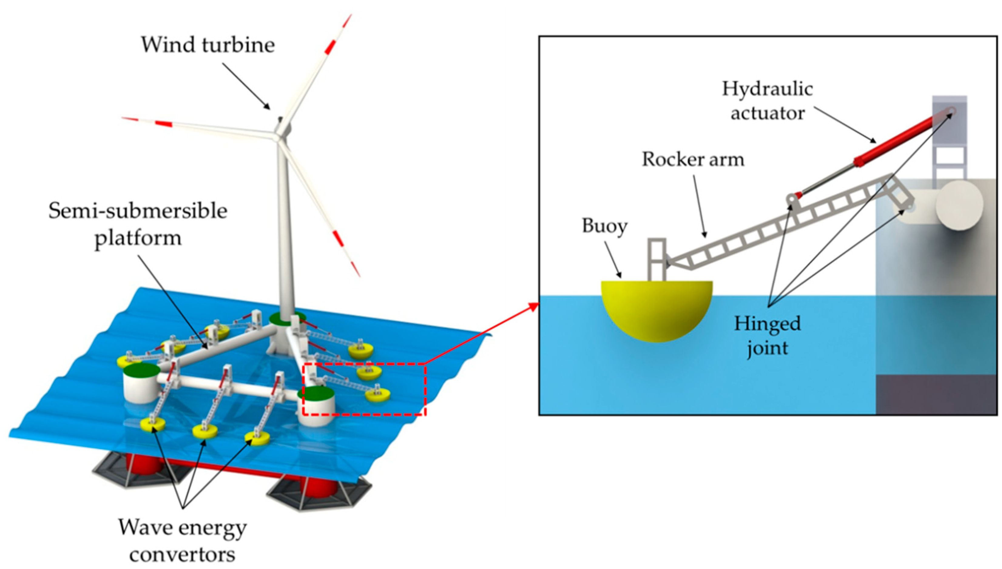
Figure 1. Conceptual design of the floating hybrid wind-wave platform system.
Jmse 10 01660 g001
Figure 2. The detailed schematic diagram of the hybrid system. (A) Simple layout, (B) enlarged image of the interconnection between buoy, rocker arm, hydraulic actuator, and the floating platform, (C) principle schematic diagram of the hydraulic PTO system.
Jmse 10 01660 g002
Figure 3. An overall diagram of the numerical simulation framework in MATLAB/Simulink.
Jmse 10 01660 g003
Figure 4. Detailed diagram of the hydraulic PTO subsystem.
Jmse 10 01660 g004
Figure 5. Conceptual design of hybrid system and wave energy converter.
Jmse 10 01660 g005
Figure 6. Conceptual design of hybrid system and wave energy converter.
Jmse 10 01660 g006
Figure 7. Influence of piston area on the performance of the hybrid system under wave height of 1.5 m. (A) Variation of CWR. (B) Variation of pitch motion RAO.
Jmse 10 01660 g007
Figure 8. Variation of optimal piston area and corresponding performance under different wave states. (A) A P power and A P motion under different wave conditions, (B) CWR* and RAO* under different wave conditions.
Jmse 10 01660 g008
Figure 9. Influence of initial gas volume of accumulator on the performance of the hybrid system under wave height of 1.5 m. (A) Variation of CWR. (B) Variation of pitch motion RAO.
Jmse 10 01660 g009
Figure 10. Influence of pre-charged pressure of accumulator on the performance of the hybrid system under wave height of 1.5 m. (A) Variation of CWR. (B) Variation of pitch motion RAO.
Jmse 10 01660 g010
Figure 11. Influence of orifice size of throat valve on the performance of the hybrid system under wave height of 1.5 m. (A) Variation of CWR. (B) Variation of pitch motion RAO.
Jmse 10 01660 g011
Figure 12. Influence of displacement of hydraulic motor on the performance of the hybrid system under wave height of 1.5 m. (A) Variation of CWR. (B) Variation of pitch motion RAO.
Jmse 10 01660 g012
Figure 13. Influence of displacement of hydraulic motor on the performance of the hybrid system under wave height of 1.5 m. (A) Variation of CWR. (B) Variation of pitch motion RAO.
Jmse 10 01660 g013
Figure 14. Influence of effective damping of generator on the performance of the hybrid system under wave height of 1.5 m. (A) Variation of CWR. (B) Variation of pitch motion RAO.
Jmse 10 01660 g014
Figure 15. Influence of pre-charged pressure of accumulator on the performance of the hybrid system under wave height of 1.5 m. (A) Variation of CWR. (B) Variation of pitch motion RAO.
Jmse 10 01660 g015
Table 1. Parameters of sea states.
Sea StateWave TypeWave ParametersValueUnit
OperationalRegular waveWave height1.5m
Period10s
VerificationIrregular waveSignificant wave height2m
Peak period8s
Spectrum typeJonswap/
Phase seed1/
Gamma3.3/
RegulatingRegular waveWave height1.0–2.0m
Period4–12s
Table 2. Parameters of the floating platform and wave energy converters.
ComponentsParametersValueUnit
Floating PlatformColumn diameter10.7m
Bracing diameter1.2m
Pontoon diameter1.8m
Distance between column center56.7m
Column height33.6m
Draft22.9m
Vertical distance of center of gravity
(below mean water surface line)
8.9m
Side length of hexagonal heave damping plate13.7m
Thickness of heave plate0.1m
Total displacement7.11 × 106kg
Roll inertia about center of mass5.49 × 109kg·m2
Pitch inertia about center of mass5.49 × 109kg·m2
Yaw inertia about center of mass6.88 × 109kg·m2
BuoyDiameter at mean water surface line5.27m
Draft2.59m
Vertical distance of center of gravity
(below mean water surface line)
−0.67m
Total displacement2.76 × 104kg
Roll inertia about center of mass4.75 × 104kg·m2
Pitch inertia about center of mass4.75 × 104kg·m2
Yaw inertia about center of mass6.19 × 104kg·m2
Rocker armLength of rocker arm, L16.28m
Initial length of hydraulic actuator, a12.47m
Horizontal distance between rocker arm hinge point and support beam, b2m
Distance between hinge point of hydraulic cylinder and hinge point of rocker arm, c8.14m
Table 3. Parameters of the hydraulic PTO system.
ComponentsParametersDefault ValueUnit
Hydraulic ActuatorPiston diameter220mm
Rod diameter180mm
AccumulatorInitial gas volume of accumulator30L
Pre-charged gas pressure of accumulator60bar
Throttle ValveThrottle valve coefficient1.35 × 10−5(m7/kg)0.5
Orifice size of throttle valve0.0005m2
Hydraulic Motor
and Electric Generator
Hydraulic motor displacement22.9cc/rev
Equivalent moment of inertia of hydraulic motor and electric generator2kg·m2
Equivalent damping of electric generator13.7N·m/rad/s
Table 4. Detailed value ranges of the case studies.
Investigation ParametersDefault ValueInvestigation RangesUnit
RangesStep
Piston area, A P 0.012560.006–0.0180.002m2
Initial gas volume of accumulator,   V g 0 4010–7010L
Pre-charged gas pressure of accumulator,   P pre 52–81MPa
Flow area of throttle valve,   A v 0.00050.0001–0.0010.0001m2
Hydraulic motor displacement,   D M 250150–35020cc/rev
Equivalent damping of electric generator,   B G 1.80.8–2.8 N·m/rad/s
Table 5. Parameters of the solver.
Solver ParametersValueUnit
Solver Typeode4/
Simulation Duration300s
Simulation Time-Step0.01s
Convolution Time15s
Wave Ramp Time Length30s
Publisher’s Note: MDPI stays neutral with regard to jurisdictional claims in published maps and institutional affiliations.