
Morphological Analysis of a Nearshore Nourishment along the Atlantic Coast of New Jersey, USA

 , ,
, ,
Abstract
1. Introduction
2. Materials and Methods
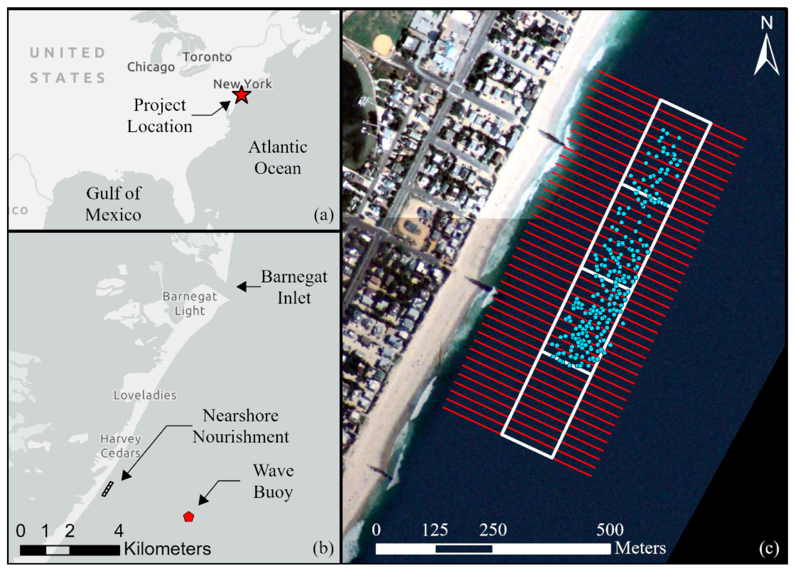
2.1. Study Site
2.2. In Situ Instruments
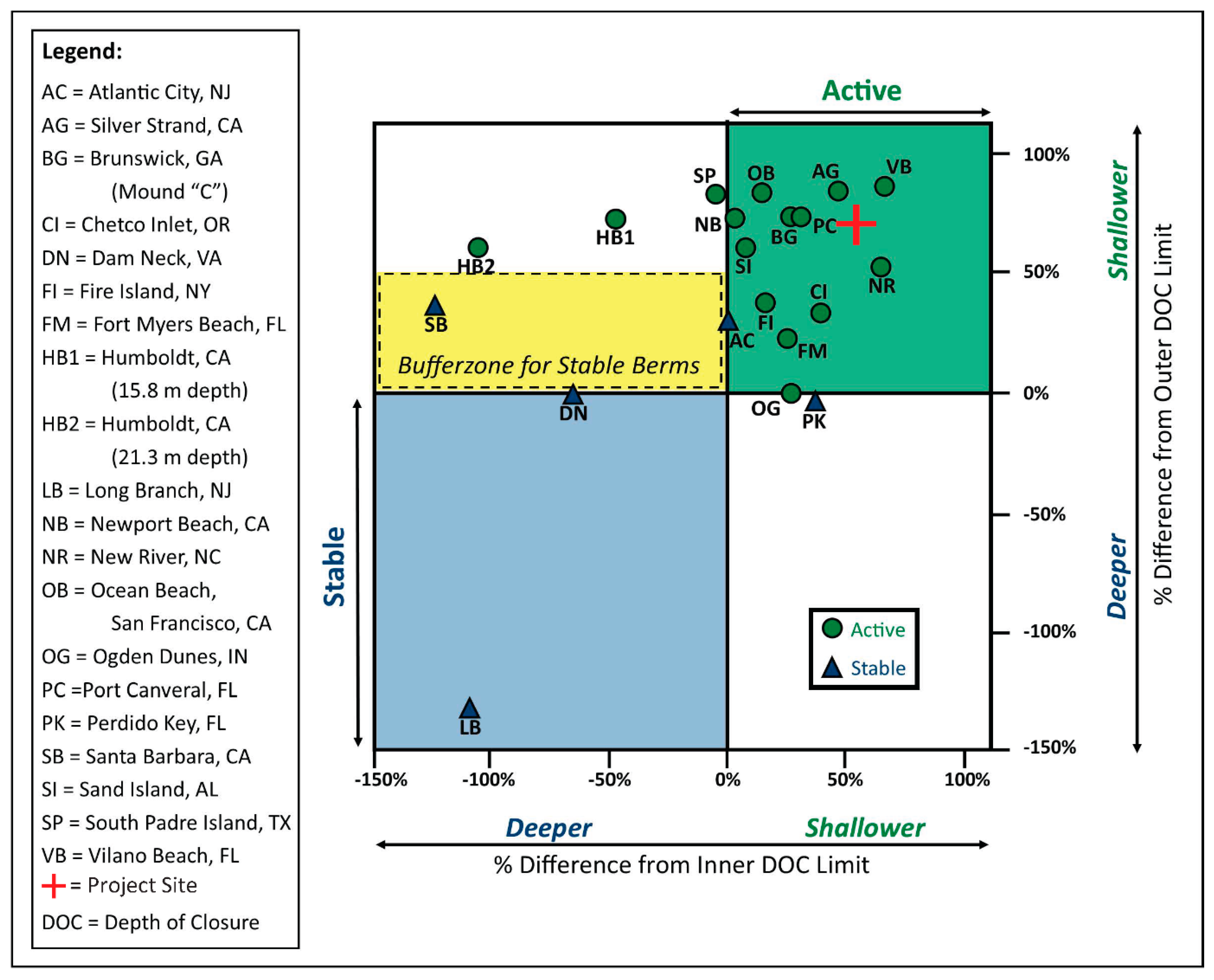
2.3. Site Evaluation for Nearshore Nourishment
2.4. Surveys
2.5. Deflation Code
2.6. Satellite Analysis
3. Results
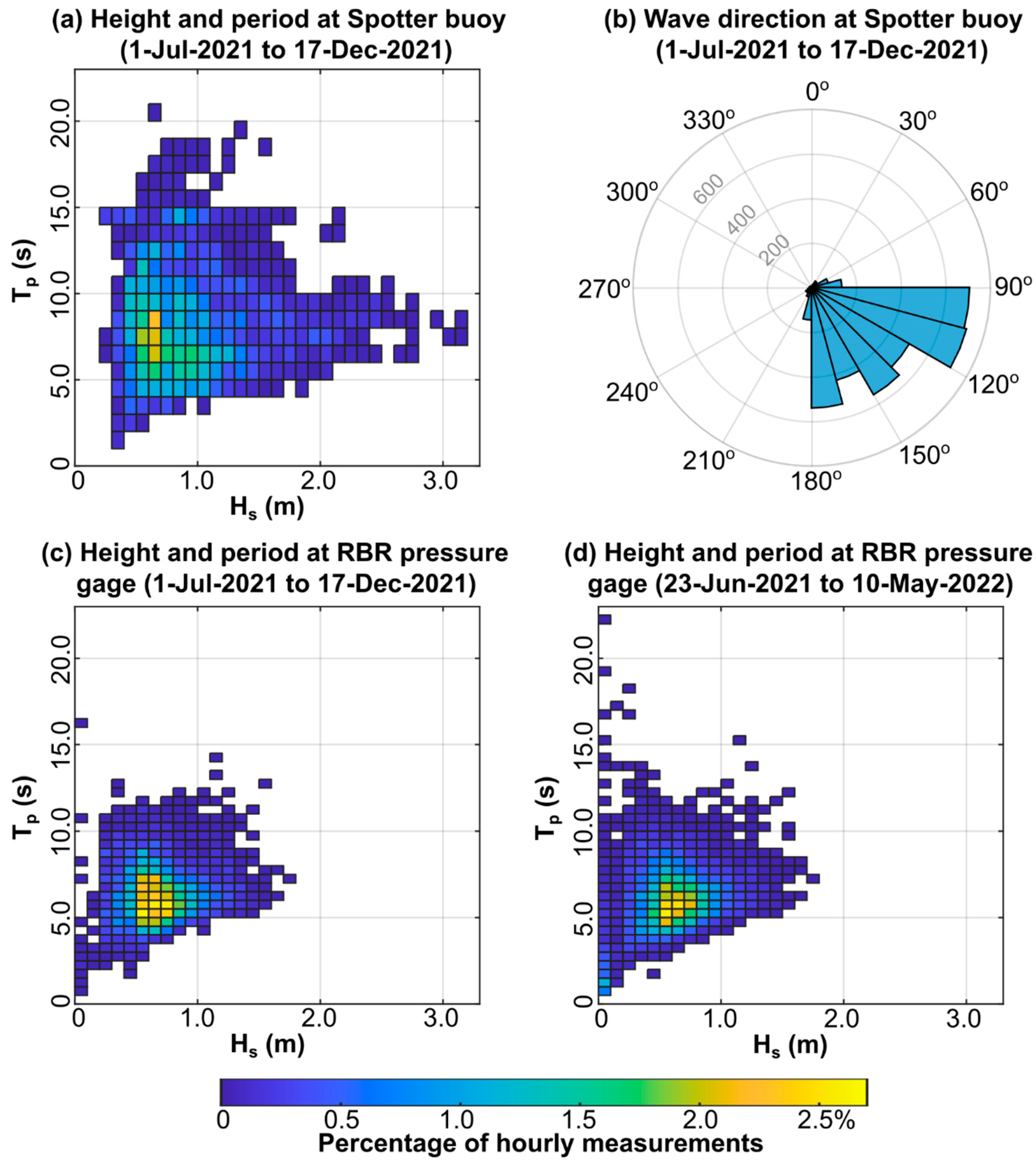
3.1. Wave Analysis
3.2. Site Evaluation for Nearshore Nourishment
3.3. Surveys
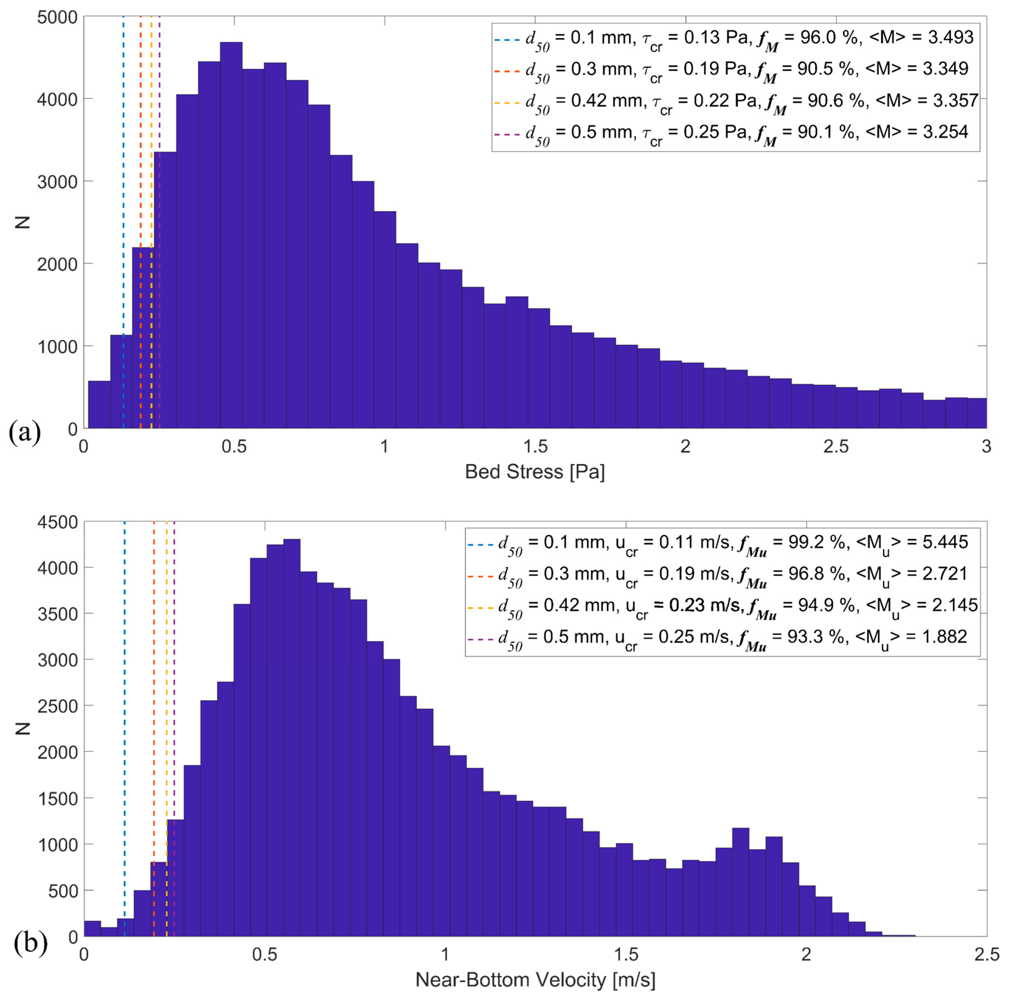
3.4. Deflation Results
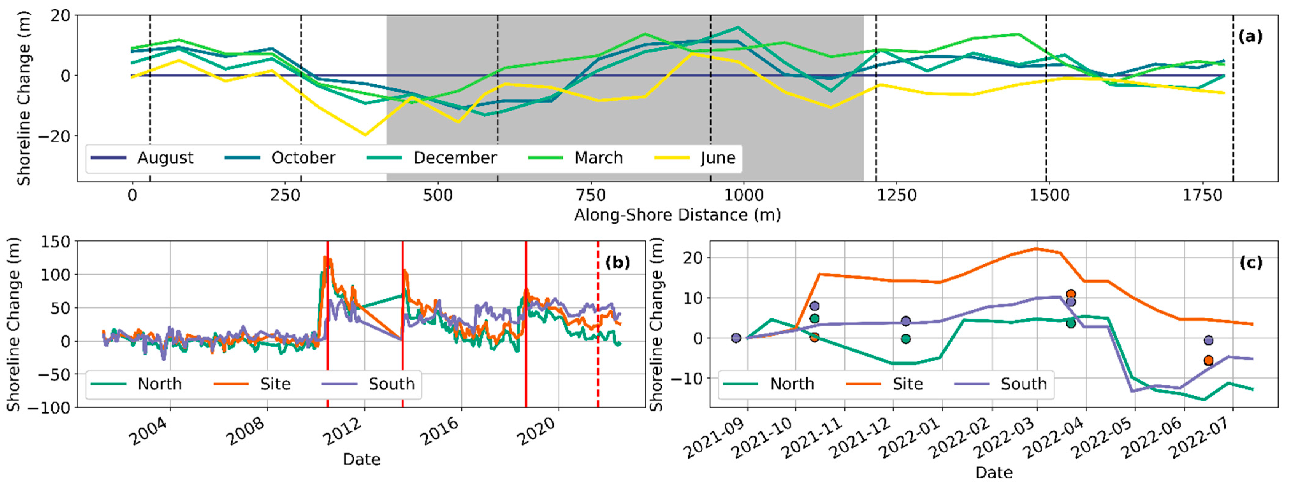
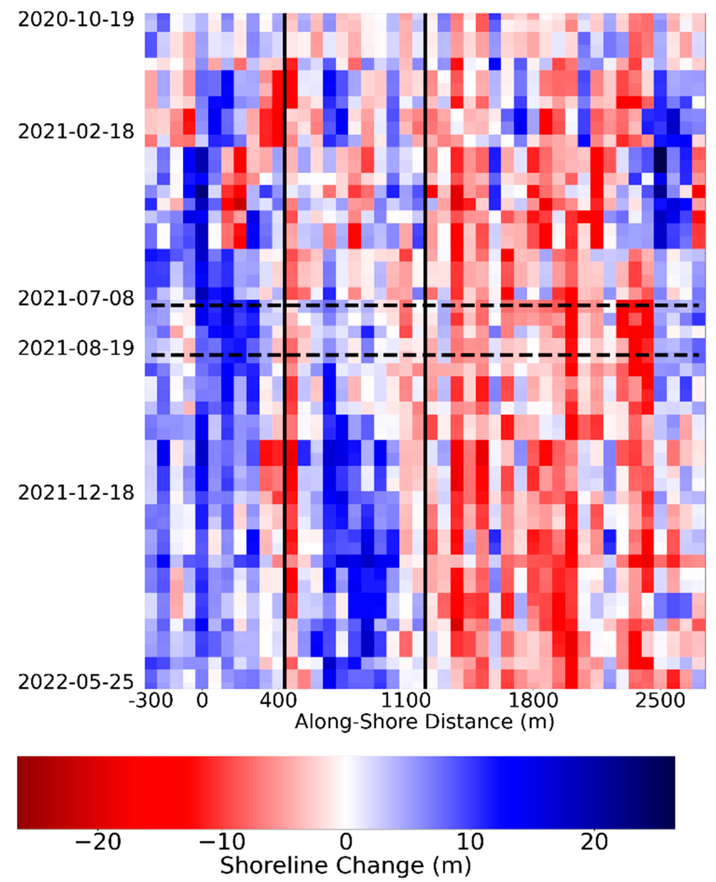
3.5. Shoreline Change
4. Discussion
5. Conclusions
Author Contributions
Funding
Institutional Review Board Statement
Data Availability Statement
Acknowledgments
Conflicts of Interest
References
- Zwamborn, J.A.; Fromme, G.A.W.; Fitzpatrick, J.B. Underwater mound for the protection of Durban’s beaches. In Proceedings of the 12th International Conference on Coastal Engineering, Washington, DC, USA, 13–18 September 1970. [Google Scholar]
- Vera-Cruz, D. Artificial nourishment of Copacabana beach. In Proceedings of the 13th International Conference on Coastal Engineering, Vancouver, BC, Canada, 10–14 July 1972. [Google Scholar]
- Hanson, H.; Brampton, A.; Capobianco, M.; Dette, H.H.; Hamm, L.; Laustrup, C.; Lechuga, A.; Spanhoff, R. Beach nourishment projects, practices, and objectives—A European overview. Coast. Eng. 2002, 47, 81–111. [Google Scholar] [CrossRef]
- Lodder, Q.J.; Sørensen, P. Comparing the Morphological Behaviour of Dutch–Danish Shoreface Nourishments. In Proceedings of the Coastal Management: Changing Coast, Changing Climate, Changing Minds, Amsterdam, The Netherlands, 8–9 September 2015. [Google Scholar]
- Pinto, C.A.; Taborda, R.; Andrade, C.; Baptista, P.; Silva, P.A.; Mendes, D.; Pais-Barbosa, J. Morphological Development and Behaviour of a Shoreface Nourishment in the Portuguese Western Coast. J. Mar. Sci. Eng. 2022, 10, 146. [Google Scholar] [CrossRef]
- Mendes, D.; Pais-Barbosa, J.; Baptista, P.; Silva, P.A.; Bernardes, C.; Pinto, C. Beach Response to a Shoreface Nourishment (Aveiro, Portugal). J. Mar. Sci. Eng. 2021, 9, 1112. [Google Scholar] [CrossRef]
- Walker, B.M.; Krafft, D.R.; McFall, B.C.; McCaw, H.; Spurgeon, S.L. Current State of Practice of Nearshore Nourishment by the United States Army Corps of Engineers; ERDC/CHL SR-22-4; U.S. Army Corps of Engineers Engineer Research and Development Center: Vicksburg, MS, USA, 2022; 49p. [Google Scholar] [CrossRef]
- Brand, E.; Ramaekers, G.; Lodder, Q. Dutch experience with sand nourishments for dynamic coastline conservation—An operational overview. Ocean Coast. Manag. 2022, 217, 106008. [Google Scholar] [CrossRef]
- McFall, B.C.; Krafft, D.R.; McCaw, H.; Walker, B.M. Metrics of Success for Nearshore Nourishment Projects Constructed with Dredged Sediment; ERDC/TN RSM-21-3; U.S. Army Corps of Engineers Engineer Research and Development Center: Vicksburg, MS, USA, 2021; 13p. [Google Scholar] [CrossRef]
- Wang, P.; Brutsché, K.E.; Beck, T.M.; Rosati, J.D.; Lillycrop, L.S. Initial Morphologic Evolution of Perdido Key Berm Nourishment, Florida; ERDC/CHL CHETN-IV-89; U.S. Army Corps of Engineers Engineer Research and Development Center: Vicksburg, MS, USA, 2013; 10p, Available online: http://hdl.handle.net/11681/2001 (accessed on 7 October 2022).
- Brutsché, K.E.; Wang, P.; Beck, T.M.; Rosati, J.D.; Legault, K.R. Morphological evolution of a submerged artificial nearshore berm along a low-wave microtidal coast, Fort Myers Beach, west central Florida, USA. Coast. Eng. 2014, 91, 29–44. [Google Scholar] [CrossRef]
- Brutsché, K.E.; McFall, B.C.; Li, H.; McNinch, J.E.; Ousley, J.D.; Engle, J.A.; Maglio, C.K. Strategic nearshore placement of dredged sediment at Vilano Beach, Florida. Shore Beach 2017, 85, 77–84. [Google Scholar]
- Otay, E.N. Monitoring results of a nearshore disposal berm. In Proceedings of the Coastal Dynamics ‘95, Gdańsk, Poland, 4–8 September 1995. [Google Scholar]
- Armstrong, S.B.; Lazarus, E.D.; Limber, P.W.; Goldstein, E.B.; Thorpe, C.; Ballinger, R.C. Indications of a Positive Feedback between Coastal Development and Beach Nourishment: Coastal Development Beach Nourishment. Earth’s Future 2016, 4, 626–635. [Google Scholar] [CrossRef]
- McFall, B.C.; Brutsché, K.E.; Ousley, J.D.; Maglio, C.K.; Engle, J.A. Innovative nearshore berm placement techniques at Vilano Beach, FL, and application of the sediment mobility tool. World Dredg. 2017, 51, 34–35. [Google Scholar]
- Krafft, D.R.; Young, D.L.; Brutsché, K.E.; McFall, B.C.; Bruder, B.L. Nearshore Placement Workshop 2019: Sediment Nourishment of the Nearshore Environment; ERDC/CHL SR-20-02; U.S. Army Corps of Engineers Engineer Research and Development Center: Vicksburg, MS, USA, 2020; 28p. [Google Scholar] [CrossRef]
- van Duin, M.J.P.; Wiersma, N.R.; Walstra, D.J.R.; Van Rijn, L.C.; Stive, M.J.F. Nourishing the shoreface: Observations and hindcasting of the Egmond case, The Netherlands. Coast. Eng. 2004, 51, 813–837. [Google Scholar] [CrossRef]
- Hamilton, D.G.; Ebersole, B.A.; Smith, E.R.; Wang, P. Development of a Large-Scale Laboratory Facility for Sediment Transport Study; ERDC/CHL TR-01-22; U.S. Army Corps of Engineers Engineer Research and Development Center: Vicksburg, MS, USA, 2001; 187p, Available online: http://hdl.handle.net/11681/7560 (accessed on 7 October 2022).
- Smith, E.R.; Mohr, M.C.; Chader, S.A. Laboratory experiments on beach change due to nearshore mound placement. Coast. Eng. 2017, 121, 119–128. [Google Scholar] [CrossRef]
- Hands, E.B.; Allison, M.C. Mound migration in deeper water and methods of categorizing active and stable depths. In Proceedings of the Coastal Sediments ‘91, Seattle, WA, USA, 25–27 June 1991. [Google Scholar]
- Ahrens, J.P.; Hands, E.B. Parameterizing Beach Erosion/Accretion Conditions. In Proceedings of the Coastal Engineering 1998, Cophenhagen, Denmark, 22–26 June 1998. [Google Scholar] [CrossRef]
- Huisman, B.J.A.; Walstra, D.-J.R.; Radermacher, M.; de Schipper, M.A.; Ruessink, B.G. Observations and Modelling of Shoreface Nourishment Behaviour. J. Mar. Sci. Eng. 2019, 7, 59. [Google Scholar] [CrossRef]
- Priestas, A.M.; McFall, B.C.; Brutsché, K.E. Performance of Nearshore Berms from Dredged Sediments: Validation of the Sediment Mobility Tool; ERDC/CHL TR-19-19; U.S. Army Corps of Engineers Engineer Research and Development Center: Vicksburg, MS, USA, 2019; 63p. [Google Scholar] [CrossRef]
- McFall, B.C.; Brutsché, K.E.; Priestas, A.M.; Krafft, D.R. Evaluation Techniques for the Beneficial Use of Dredged Sediment Placed in the Nearshore. J. Waterw. Port Coast. Ocean Eng. 2021, 147, 04021016. [Google Scholar] [CrossRef]
- Douglass, S.L. Estimating landward migration of nearshore constructed sand mounds. J. Waterw. Port Coast. Ocean Eng. 1995, 121, 247–250. [Google Scholar] [CrossRef]
- Larson, M.; Ebersole, B.A. An Analytical Model to Predict the Response of Mounds Placed in the Offshore; ERDC/CHL CETN-II-42; U.S. Army Corps of Engineers Engineer Research and Development Center: Vicksburg, MS, USA, 1999; 13p, Available online: http://hdl.handle.net/11681/2124 (accessed on 7 October 2022).
- Johnson, C.L.; McFall, B.C.; Krafft, D.R.; Brown, M.E. Sediment Transport and Morphological Response to Nearshore Nourishment Projects on Wave-Dominated Coasts. J. Mar. Sci. Eng. 2021, 9, 1182. [Google Scholar] [CrossRef]
- Smith, E.R.; D’Alessandro, F.; Tomasicchio, G.R.; Gailani, J.Z. Nearshore placement of a sand dredged mound. Coast. Eng. 2017, 126, 1–10. [Google Scholar] [CrossRef]
- Bryant, D.B.; McFall, B.C. Transport of nearshore dredge material berms. In Proceedings of the 6th International Conference on Application of Physical Modelling in Coastal and Port Engineering and Science, Ottawa, ON, Canada, 10–13 May 2016. [Google Scholar]
- de Schipper, M.A.; de Vries, S.; Ranasinghe, R.; Reniers, A.J.H.M.; Stive, M.J.F. Morphological developments after a beach and shoreface nourishment at Vlugtenburg beach. In Proceedings of the NCK-days 2012: Crossing borders in coastal research, Enschede, The Netherlands, 13–16 March 2012. [Google Scholar]
- Gijsman, R.; Visscher, J.; Schlurmann, T. A method to systematically classify design characteristics of sand nourishments. In Proceedings of the 36th International Conference on Coastal Engineering, Baltimore, MD, USA, 30 July–3 August 2018. [Google Scholar] [CrossRef]
- Young, D.L.; Brutsché, K.E.; Li, H.; McFall, B.C.; Maloney, E.C.; McClain, K.E.; Bucaro, D.F.; LeRoy, J.Z.; Duncker, J.J.; Johnson, K.K.; et al. Analysis of Nearshore Placement of Sediments at Ogden Dunes, Indiana; ERDC/CHL TR-20-4; U.S. Army Corps of Engineers Engineer Research and Development Center: Vicksburg, MS, USA, 2020; 98p. [Google Scholar] [CrossRef]
- de Looff, H.; Welp, T.; Snider, N.; Wilmink, R. Chapter 7: Adaptive Management. In International Guidelines on Natural and Nature-Based Features for Flood Risk Management; Bridges, T.S., King, J.K., Simm, J.D., Beck, Collins, G., Lodder, Q., Mohan, R.K., Eds.; U.S. Army Corps of Engineers Engineer Research and Development Center: Vicksburg, MS, USA, 2021. [Google Scholar]
- Lodder, Q.; Jeuken, C.; Reinen-Hamill, R.; Burns, O.; Ramsdell, R., III; de Vries, J.; McFall, B.; IJff, S.; Maglio, C.; Wilmink, R. Chapter 9: Beaches and Dunes. In International Guidelines on Natural and Nature-Based Features for Flood Risk Management; Bridges, T.S., King, J.K., Simm, J.D., Beck, Collins, G., Lodder, Q., Mohan, R.K., Eds.; U.S. Army Corps of Engineers Engineer Research and Development Center: Vicksburg, MS, USA, 2021. [Google Scholar]
- Tyler, Z.J.; McFall, B.C.; Brutsché, K.E.; Maloney, E.C.; Bucaro, D.F. Physical Monitoring Methods for the Nearshore Placement of Dredged Sediment; ERDC/TN RSM-18-6; U.S. Army Corps of Engineers Engineer Research and Development Center: Vicksburg, MS, USA, 2018; 13p. [Google Scholar] [CrossRef]
- van Rees, C.B.; Naslund, L.; Hernandez-Abrams, D.D.; McKay, S.K.; Woodson, C.B.; Rosemond, A.; McFall, B.; Altman, S.; Wenger, S.J. A strategic monitoring approach for learning to improve natural infrastructure. Sci. Total Environ. 2022, 832, 155078. [Google Scholar] [CrossRef]
- Arnold, D.E.; McFall, B.C.; Brutsché, K.E.; Maloney, E.C.; Bucaro, D.F. Nearshore Placement Techniques in Southern Lake Michigan; ERDC/CHL TR-18-3; U.S. Army Corps of Engineers Engineer Research and development Center: Vicksburg, MS, USA, 2018; 45p. [Google Scholar] [CrossRef]
- USACE Philadelphia District. WRDA 2016 Section 1122 Beneficial Use of Dredged Material Pilot Program: Beneficial Use Placement Opportunities in New Jersey Using Navigation Channel Sediments–Barnegat Inlet. 2021. Available online: https://www.nap.usace.army.mil/Portals/39/docs/Civil/Coastal/Barnegat-Inlet-Section-1122-April-2021.pdf?ver=mDQWxLcR_kkLqf_2ndOvIg%3D%3D (accessed on 7 October 2022).
- Harris, B.D.; McGill, S.P.; Krafft, D.R.; McFall, B.C.; Chasten, M.A.; Bain, R.L. Beneficial Use of Dredged Material for Beach Erosion Mitigation at Harvey Cedars, New Jersey. World Dredg. 2022, 55, 10–11. [Google Scholar]
- Vos, K.; Splinter, K.D.; Harley, M.D.; Simmons, J.A.; Turner, I.L. CoastSat: A Google Earth Engine-enabled Python toolkit to extract shorelines from publicly available satellite imagery. Environ. Model. Softw. 2019, 122, 104528. [Google Scholar] [CrossRef]
- Cialone, M.A.; Thompson, E.F. Wave Climate and Littoral Sediment Transport Potential, Long Beach Island, New Jersey; ERDC/CHL TR-00-21; U.S. Army Corps of Engineers Engineer Research and Development Center: Vicksburg, MS, USA, 2000; 75p, Available online: http://hdl.handle.net/11681/7451 (accessed on 7 October 2022).
- Dally, W.R.; Osiecki, D.A. Evaluating the Impact of Beach Nourishment on Surfing: Surf City, Long Beach Island, New Jersey, U.S.A. J. Coast. Res. 2018, 34, 793–805. [Google Scholar] [CrossRef]
- Hallermeier, R.J. Uses for a calculated limit depth to beach erosion. In Proceedings of the 16th International Conference on Coastal Engineering, Hamburg, Germany, 27 August–3 September 1978; pp. 1493–1512. [Google Scholar]
- Hallermeier, R.J. A profile zonation for seasonal sand beaches from wave climate. Coast. Eng. 1981, 4, 253–277. [Google Scholar] [CrossRef]
- Birkemeier, W.A. Field data on seaward limit of profile change. J. Waterw. Port Coast. Ocean Eng. 1985, 111, 598–602. [Google Scholar] [CrossRef]
- Brutsché, K.E.; Rosati III, J.; Pollock, C.E.; McFall, B.C. Calculating Depth of Closure Using WIS Hindcast Data; ERDC/CHL CHETN-VI-45; U.S. Army Corps of Engineers Engineer Research and Development Center: Vicksburg, MS, USA, 2016; 9p, Available online: http://hdl.handle.net/11681/20259 (accessed on 7 October 2022).
- McFall, B.C.; Smith, S.J.; Pollock, C.E.; Rosati, J.; Brutsché, K.E. Evaluating Sediment Mobility for Sitting Nearshore Berms; ERDC/CHL CHETN-IV-108; U.S. Army Corps of Engineers Engineer Research and Development Center: Vicksburg, MS, USA, 2016; 11p, Available online: http://hdl.handle.net/11681/20282 (accessed on 7 October 2022).
- Larson, M.; Kraus, N.C. Analysis of Cross-Shore Movement of Natural Longshore Bars and Material Placed to Create Longshore Bars; Technical Rep. No. DRP-92-5; Department of the Army, Waterways Experiment Station, Corps of Engineers: Vicksburg, MS, USA, 1992; 124p, Available online: http://hdl.handle.net/11681/4617 (accessed on 7 October 2022).
- McFall, B.C.; Brutsché, K.E. User’s Guide for the Sediment Mobility Tool Web Application; ERDC/TN RSM-18-4; U.S. Army Corps of Engineers Engineer Research and Development Center: Vicksburg, MS, USA, 2018; 11p. [Google Scholar] [CrossRef]
- Komar, P.D. Beach Processes and Sedimentation, 2nd ed; Prentice Hall: Upper Saddle River, NJ, USA, 1998. [Google Scholar]
- Dean, R.G.; Dalrymple, R.A. Coastal Processes with Engineering Applications; Cambridge University Press: Cambridge, UK, 2002. [Google Scholar]
- Dean, R.G. Beach Nourishment: Theory and Practice; Advanced Series on Ocean Engineering, vol. 18; World Scientific Publishing Company Inc.: Hackensack, NJ, USA, 2002. [Google Scholar]
- Soulsby, R.L. Dynamics of Marine Sands; Thomas Telford Publications: London, UK, 1997. [Google Scholar]
- Bain, R.; McFall, B.; Krafft, D.; Hudson, A. Evaluating Transport Formulations for Application to Nearshore Berms. J. Waterw. Port Coast. Ocean Eng. 2021, 147, 4021031. [Google Scholar] [CrossRef]
- Shaeri, S.; Etemad-Shahidi, A.; Tomlinson, R. Revisiting Longshore Sediment Transport Formulas. J. Waterw. Port Coast. Ocean Eng. 2020, 146, 4020009. [Google Scholar] [CrossRef]
- Dronkers, J. Dynamics of Coastal Systems, 2nd ed.; World Scientific Publishing: Hackensack, NJ, USA, 2016. [Google Scholar]
- Hudson, A.; Moritz, H.R.; Norton, J. Sediment Mobility, Closure Depth, and the Littoral System–Oregon and Washington Coast; ERDC/TN RSM-22-7; U.S. Army Corps of Engineers Engineer Research and Development Center: Vicksburg, MS, USA, 2022; 10p. [Google Scholar] [CrossRef]
- Otsu, N. A Threshold Selection Method from Gray-Level Histograms. IEEE Trans. Syst. Man Cybern. 1979, 9, 62–66. [Google Scholar] [CrossRef]
- Grunnet, N.M.; Ruessink, B.G. Morphodynamic response of nearshore bars to a shoreface nourishment. Coast. Eng. 2005, 52, 119–137. [Google Scholar] [CrossRef]
- Vos, K.; Harley, M.D.; Splinter, K.D.; Simmons, J.A.; Turner, I.L. Sub-annual to multi-decadal shoreline variability from publicly available satellite imagery. Coast. Eng. 2019, 150, 160–174. [Google Scholar] [CrossRef]


| Sensor | Location | Approximate Depth | Timing |
|---|---|---|---|
| RBR Virtuoso (Pressure) | 630 m North of the nourishment | 1.5 m | 23 June 2021 to 10 May 2022 |
| Nortek Signature 1000 (ADCP) | Seaward of the nourishment | 8.0 m | 7 December 2021 to 15 April 2022 |
| Sofar Spotter buoy (Spectral wave info) | 3 km offshore of nourishment | 15.2 m | 1 July 2021 to 17 December 2021 |
| Survey Type | Date | Period | Notes |
|---|---|---|---|
| Single-Beam | 13 May 2021 | Pre-Nourishment | - |
| Multi-Beam | 22 July 2021 | During Construction | - |
| Multi-Beam | 28 July 2021 | During Construction | - |
| Multi-Beam | 9 August 2021 | During Construction | - |
| Single- and Multi-Beam | 25 August 2021 | Post Placement | 6 days post construction |
| Single- and Multi-Beam | 13 October 2021 | Post Placement | 55 days post construction |
| Single- and Multi-Beam | 9 December 2021 | Post Placement | 112 days post construction |
| Single-Beam | 22 March 2022 | Post Placement | 215 days post construction |
| Single-Beam | 17 June 2022 | Post Placement | 302 days post construction |
| Parameter | Value (Treated as Time-Invariant) |
|---|---|
| Shore angle | 210° |
| Landward boundary of initial placement footprint | 168 m |
| Cross-shore distance to initial placement crest | 198 m |
| Seaward boundary of initial placement footprint | 290 m |
| Water depth at landward placement boundary | 3.0 m |
| Water depth at initial placement crest | 2.5 m |
| Water depth at seaward placement boundary | 7.9 m |
| Shore-parallel length of placement | 427 m |
| Representative beach slope | 0.03 |
| d50 of placed sediment | 0.42 mm |
| Water density | 1025 kg/m3 |
| Sediment density | 2650 kg/m3 |
| Sediment porosity | 0.4 |
| tstart | tend | Predicted Volume Loss from Original Placement Footprint between tstart and tend (m3) * | ||||
|---|---|---|---|---|---|---|
| Southward | Northward | Onshore | Offshore | Sum of All Directions | ||
| 25 August 2021 | 13 October 2021 | 1800 | 1200 | 7100 | 0 | 10,100 |
| 13 October 2021 | 9 December 2021 | 2900 | 1800 | 7500 | 0 | 12,200 |
| 9 December 2021 | 22 March 2022 | 12,000 | 14,300 | 16,800 | 0 | 43,100 |
| 25 August 2021 | 22 March 2022 | 16,700 | 17,300 | 31,400 | 0 | 65,400 |
Publisher’s Note: MDPI stays neutral with regard to jurisdictional claims in published maps and institutional affiliations. |
© 2022 by the authors. Licensee MDPI, Basel, Switzerland. This article is an open access article distributed under the terms and conditions of the Creative Commons Attribution (CC BY) license (https://creativecommons.org/licenses/by/4.0/).
Share and Cite
McGill, S.P.; Harris, B.D.; McFall, B.C.; Krafft, D.R.; Bain, R.L.; Olsen, N.R.; Conery, I.W.; Chasten, M.A. Morphological Analysis of a Nearshore Nourishment along the Atlantic Coast of New Jersey, USA. J. Mar. Sci. Eng. 2022, 10, 1622. https://doi.org/10.3390/jmse10111622
McGill SP, Harris BD, McFall BC, Krafft DR, Bain RL, Olsen NR, Conery IW, Chasten MA. Morphological Analysis of a Nearshore Nourishment along the Atlantic Coast of New Jersey, USA. Journal of Marine Science and Engineering. 2022; 10(11):1622. https://doi.org/10.3390/jmse10111622
Chicago/Turabian StyleMcGill, Sean P., Brian D. Harris, Brian C. McFall, Douglas R. Krafft, Rachel L. Bain, Nicholas R. Olsen, Ian W. Conery, and Monica A. Chasten. 2022. "Morphological Analysis of a Nearshore Nourishment along the Atlantic Coast of New Jersey, USA" Journal of Marine Science and Engineering 10, no. 11: 1622. https://doi.org/10.3390/jmse10111622
APA StyleMcGill, S. P., Harris, B. D., McFall, B. C., Krafft, D. R., Bain, R. L., Olsen, N. R., Conery, I. W., & Chasten, M. A. (2022). Morphological Analysis of a Nearshore Nourishment along the Atlantic Coast of New Jersey, USA. Journal of Marine Science and Engineering, 10(11), 1622. https://doi.org/10.3390/jmse10111622