1. Introduction
Due to extreme and accidental loads, a ship’s hull girder can reach its ultimate load-carrying capacity. One of the fatal consequences of structural failure is that the ship may suffer progressive collapse due to internal and external loads during seafaring. To minimize the risk of such accidents, rules stipulate longitudinal strength assessment for all ships [
1,
2]. The objective of this assessment is to determine the ultimate strength capacity of ship hull girder when the ship is subjected to bending loads. In case of ship grounding or collision, damaged hull section reduces the bending strength further. Therefore, the ultimate strength assessment must be performed both in intact and damaged conditions to ensure that hull girder has sufficient strength reserve.
Several studies have been conducted to evaluate the ultimate strength of ship hull girder using simplified methods and are currently applied in the classification society and commercial software. Caldwell [
3] proposed an equivalent thickness approach to replace stiffened panel and used strength reduction coefficients to consider buckling. Smith [
4,
5] further refined the strength reduction coefficient method and considered that the ultimate strength of a hull girder is dependent on the strength of individual elements reaching their limit at different times. The Smith’s method has been adopted in the Common Structural Rules for Bulk Carrier and Oil Tanker, but the loading is limited to the vertical bending moment. In parallel, Ueda and Rashed [
6] proposed the idealized structural unit method (ISUM) which considers more loading scenarios. For example, ISUM can model the buckling response due to all possible hull girder sectional load components (i.e., vertical bending, horizontal bending, vertical shearing force, horizontal shearing force, and torsion). Several advanced applications of ISUM approach have been developed by Ueda et al. [
7], Masaoka et al. [
8], Fujikubo et al. [
9], Paik et al. [
10], as well as Lindemann and Kaeding [
11] for ultimate strength analyses of stiffened panel structures in different loading conditions.
The ISUM is recognized as one of the most time efficient methods for progressive collapse analysis of ship hull girder [
12]. The method has been implemented in the ALPS/HULL program within the MAESTRO FEM analysis code. The ISUM can deal with interaction between local and global failures [
13] for a short section of the ship structure. However, larger models offer a number of advantages. To capture the compartment level buckling relevant for lightweight ship structures [
14], a large-scale ship model should be considered. Larger models permit inclusion of actual pressure distributions and various load combinations. Additionally, the model length influences the post-buckling behavior, which ultimately determines the bending moment capacity [
15]. Furthermore, full ship model are advocated in [
16,
17] to minimize the boundary effect which often lead to more conservative, heavier scantlings.
The full three-dimensional finite element method (3D FEM) is an effective tool used for performing progressive collapse analysis to obtain structural strength capacity of ship hull girder. The analysis can reflect the local failure of structural members, e.g., local plate buckling and stiffener tripping, if they are modeled in detail. However, the 3D FE simulation of entire ship structure requires enormous modeling and computational effort. To reduce these while maintaining the accuracy of 3D FEM, we propose the use of equivalent single layer (ESL) approach. In the context of ship structures, ESL has been used for analysis of buckling response of panels [
18,
19], vibration response of sandwich panels [
20,
21], and ultimate strength of stiffened panels [
22,
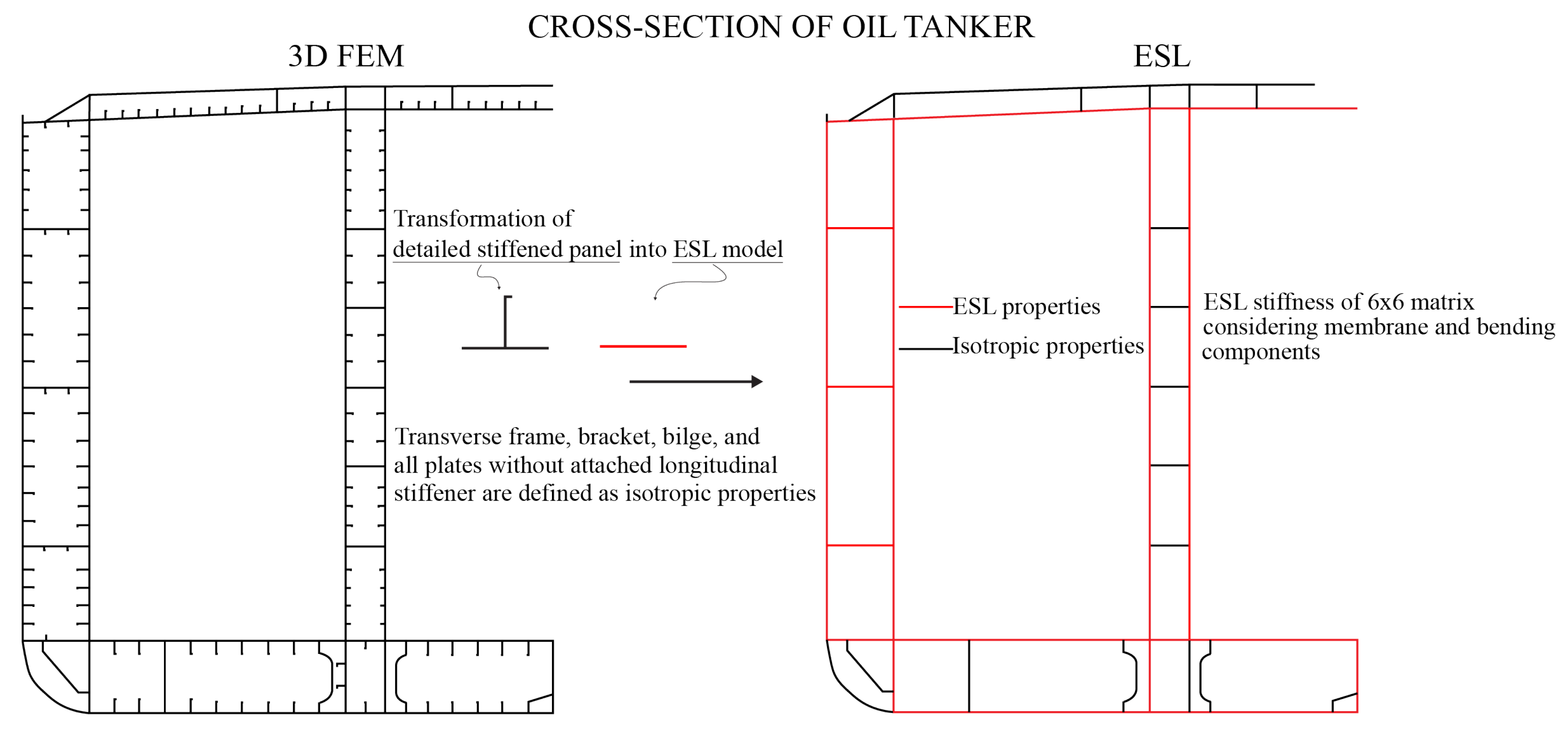
23]. However, the application examples for entire hull girder analysis are missing which this paper aims to fulfill. In the traditional FE modeling, a stiffened panel is modeled in detail composed of longitudinal stiffeners with its attached plating. Using ESL methodology, a stiffened panel is modeled as a plate without the stiffeners, but with the same stiffness as the original panel. Consequently, simplification of stiffened panels enables consideration of design alternatives without changing the FE mesh, and thus more efficient exploration of design space. Therefore, the main benefits of the ESL approach compared with 3D FE analysis are: (1) reduced modeling effort, (2) reduction in degree of freedom (DOF), and (3) reduced computational effort.
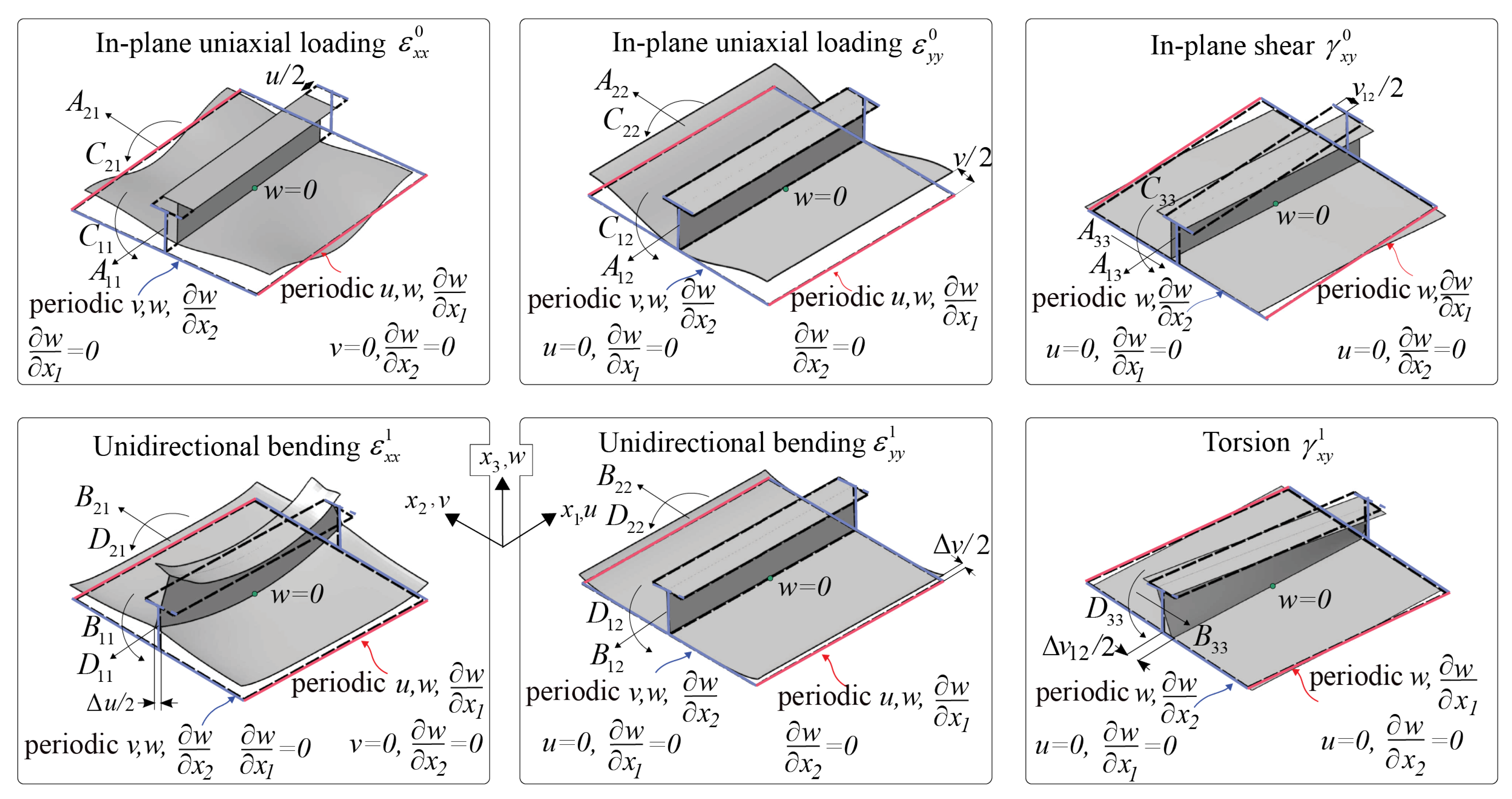
This paper presents the application of ESL approach for the ultimate strength assessment of ship hull girder and one compartment models. In the ESL model, the stiffeners are removed and shell properties are defined with equivalent stiffnesses composed of 6 × 6 membrane and bending stiffness matrices. The stiffness matrices are calculated by the first derivative of membrane force and bending moment obtained from a unit cell under six loading conditions. Two different ship-scale case studies are presented, first focusing on the compartment level analysis (Benson et al. [
14]) and second, the full-scale analysis of ship hull girder including structural damage (Tabri et al. [
24]). The ultimate strength of ship hull girder is analyzed in intact and damaged conditions due to grounding or collision. For the damage conditions, the damage extents are determined from the IACS-CSR and the structural members located in the damage extent area are removed. The distributed pressures are applied separately along the bottom and side structures of the ship to obtain the vertical and horizontal bending moment curves, respectively. For comparative purposes, analysis are also conducted with the incremental-iterative method from the IACS-CSR. The ultimate strength analysis are validated with the detailed 3D FE simulations.
3. Case Study of One Compartment Aluminium Box Girder
This paper examines the application of ESL to analysis of compartment level collapse, for details see Benson et al. [
14]. The ultimate strength of one compartment box girder was analyzed and characterized by the bending moment versus curvature curve. The analyses were performed using the detailed 3D FEM and ESL approach. The detailed 3D FE analysis utilizes conventional modeling techniques with explicit modeling of stiffened plates further strengthened with larger transverse webframes with all parts given isotropic material properties. In the ESL model, longitudinally stiffened panels were represented with equivalent single layer plates having the same stiffness as the original plate with stiffeners while webframes were still explicitly modeled.
Modeled box girder with a 8.4 m length had a square cross section, stiffened on each side by 20 longitudinals spaced 400 mm apart. The panel configuration M1 was selected for analyses, see [
14]. The longitudinal T-stiffeners had the web and flange dimensions of 120 × 55 mm and 55 × 7.7 mm, respectively. The transverse webframes were flat bars with the size of 180 × 10 mm spaced 1200 mm apart. There were six webframes between transverse bulkheads, which is sufficient to demonstrate buckling characteristics at the compartment level. To maintain the straightness of the compartment ends during bending, the bulkheads were modeled with a very large thickness. The mesh size used was 50 × 50 mm, which was determined by Benson et al. [
14] through the mesh convergence analysis. The mesh size sensitivity study of ESL was performed using element sizes of 50 × 50 mm, 300 × 300 mm and 600 × 600 mm which are consisted of 24, 4 and 2 elements between webframes, respectively. The box girder was given aluminium 5083 properties with an elastic modulus of 70 GPa and a yield stress of 302 MPa. The non-linear stress–strain response of this material was characterized by the Ramberg–Osgood relationship, as expressed in the following equation:
where
is the strain,
is the applied stress,
E is the elastic modulus,
is the 0.2% offset proof stress,
n is the exponent.
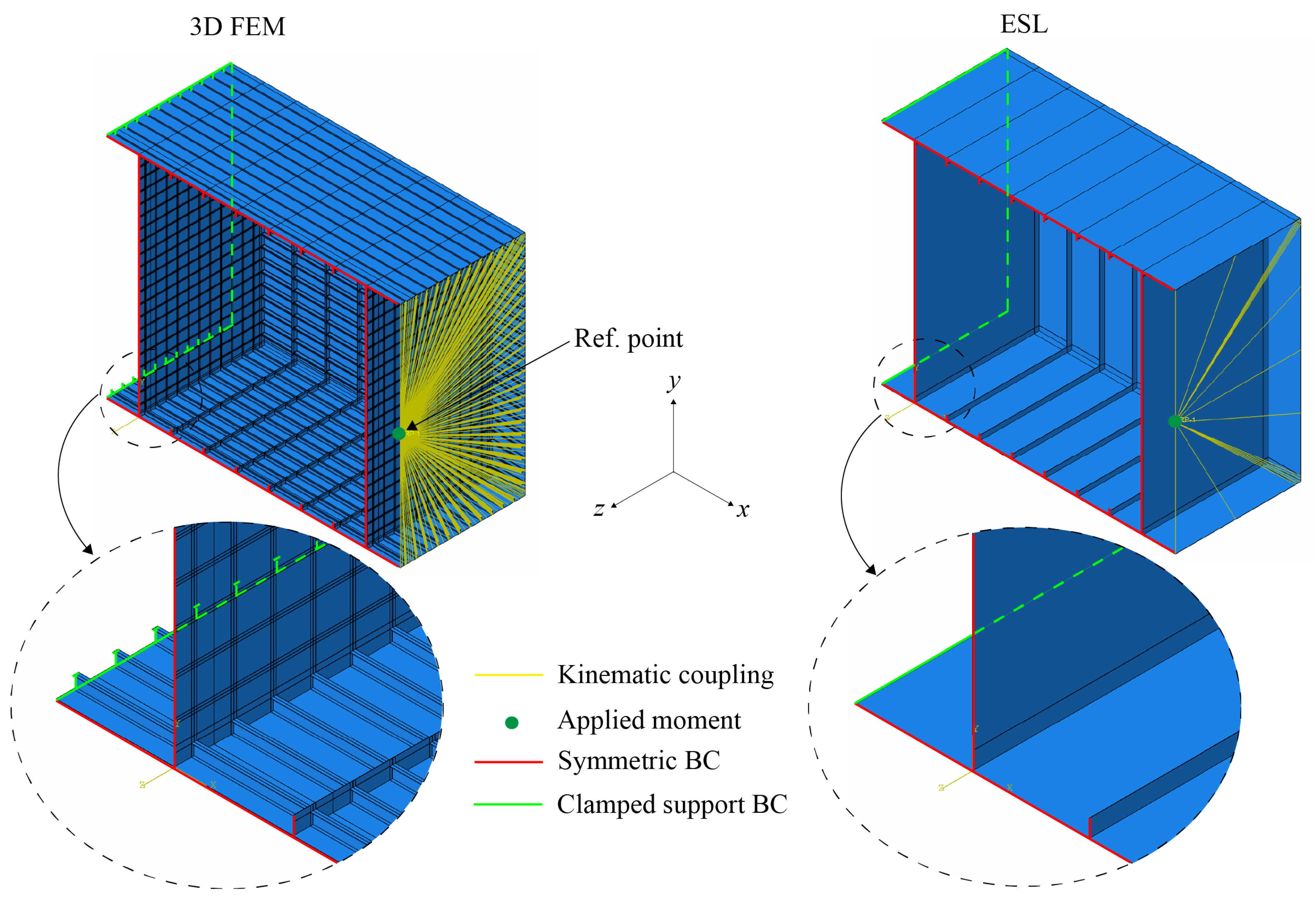
Boundary conditions applied in the box girder are explained in
Figure 4. At the reference point, a moment to the z-axis was applied resulting in compression on the top panel and tension on the bottom panel. This reference point was connected to the nodes at the boundary using kinematic coupling so that the section remained flat during rotation. At the opposite section, the clamped boundary condition was imposed. Only half of the girder was modeled by imposing symmetry on the center line.
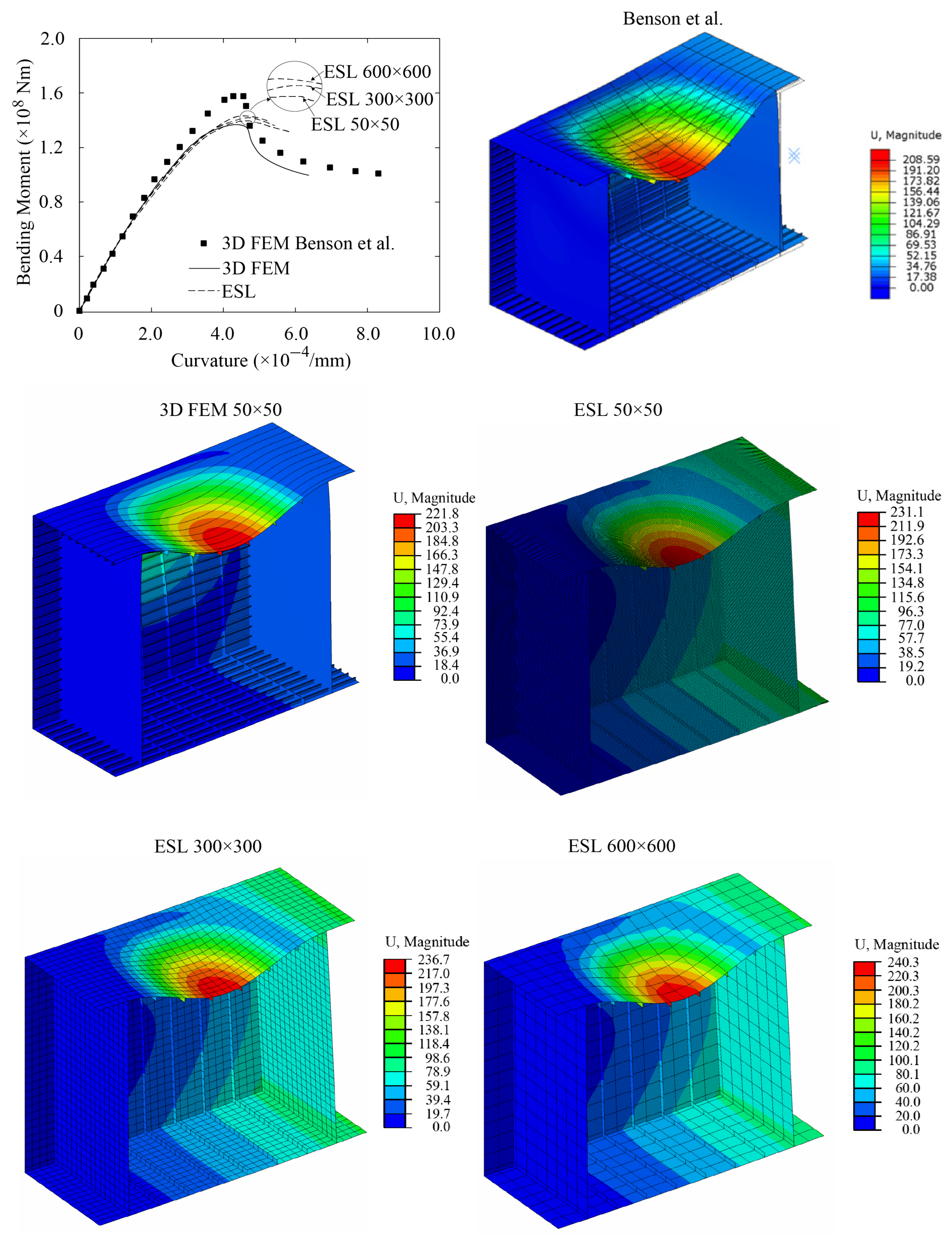
The response of the box girder is compared in terms of bending moment vs. curvature curves and overall deformations obtained at the maximum bending moment, see
Figure 5. Current 3D FE analysis gives slightly softer response compared with 3D FE results from Benson et al. [
14]. Curvature in current study was determined by tracking the rotation at the reference point. The way curvature was obtained in analysis of Benson was not detailed, which possibly explains the slightly softer response obtained with current 3D FE analysis, while the overall behavior is well captured. Proceeding to analyze differences between current 3D FEM and ESL we also note close agreement in maximum bending moment. Even the coarsest (and stiffest) ESL model of 600 × 600 mm shows the difference of mere 4.57% compared with 3D FEM result. All studied element sizes can capture accurately compartment level (overall) buckling behavior and for overall efficiency we advocate to use the largest mesh of 600 × 600 mm or two elements between webframes. However, the ESL accuracy decreases if the stiffened panel is subjected to local buckling of the stiffener web or plate [
22,
23]. Therefore, further investigation should be performed what is the suitable element size for such simulations. In the post-ultimate stage, there is a sudden decrease in bending moment due to transition from interframe to overall buckling mode. ESL model cannot accurately trace this structural response at the post-ultimate stage.
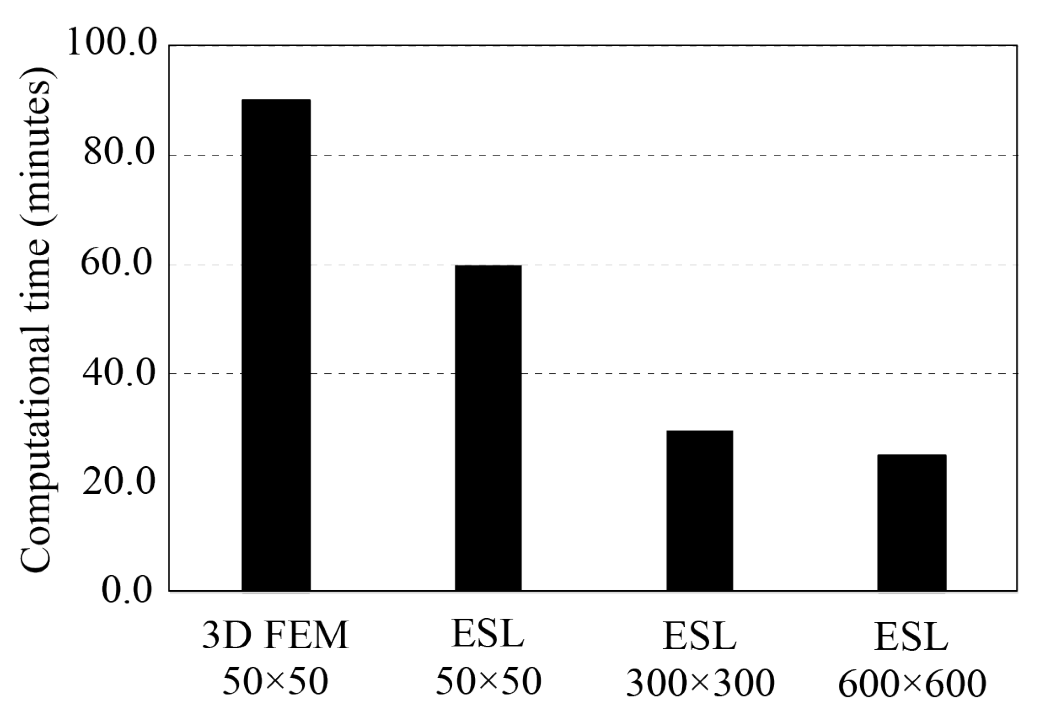
In addition to providing a high level of accuracy with coarse elements of 600 × 600 mm, ESL approach also provides shorter computation times than 3D FEM. With ESL mesh of 600 × 600 mm the computation time is only 27.7% of full 3D model, see
Figure 6. All simulations were ran with processor type of Intel(R) Xeon(R) CPU E5-2690 0 @ 2.90 GHz, 4 cores, 4 domains, and RAM of 24.0 GB.
4. Case Study of Full-Scale Steel Ship Structure
Ultimate strength analyses of ship hull girder in intact and damaged conditions were performed using the ESL approach, full 3D FEM, and incremental-iterative method from the IACS-CSR. A traditional ship hull can be considered as a light-weight thin-walled structure composed of an outer shell that is stiffened with framing members. In other words, ship hull girder is built from stiffened panels. From a design perspective, a detailed modeling of stiffened panel composed of plates and stiffeners is required for 3D FEM. However, ESL simplifies the modeling process as the plate elements are given stiffness properties representative of stiffened panels rendering explicit modeling of stiffeners unnecessary. In the IACS-CSR, ultimate strength is calculated based on a cross-section of hull girder between two adjacent transverse webframes. In
Section 2, the theory and implementation of ESL approach was explained. In this section, the full 3D FEM and incremental-iterative method are described.
4.1. Ship Particulars
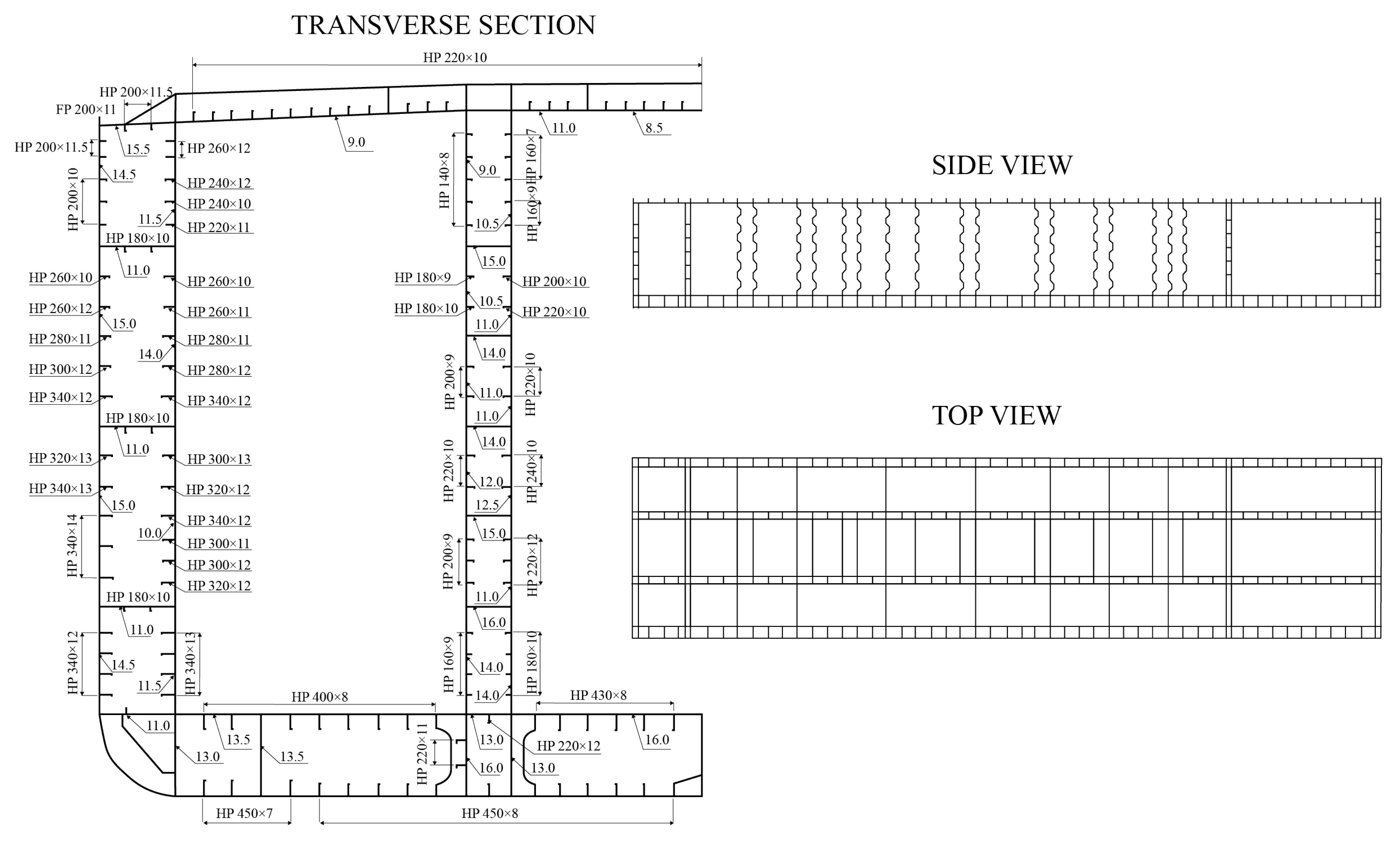
The case study structure is a chemical product tanker that was previously analyzed in Tabri et al. [
24]. The midship section and bulkhead arrangement are given in
Figure 7 and the main particulars in
Table 1. The ship is designed from high strength steel (AH36) with Young’s modulus of
210 GPa, Poisson ratio of
0.3, and yield stress of
355 MPa.
4.2. Loading and Boundary Conditions
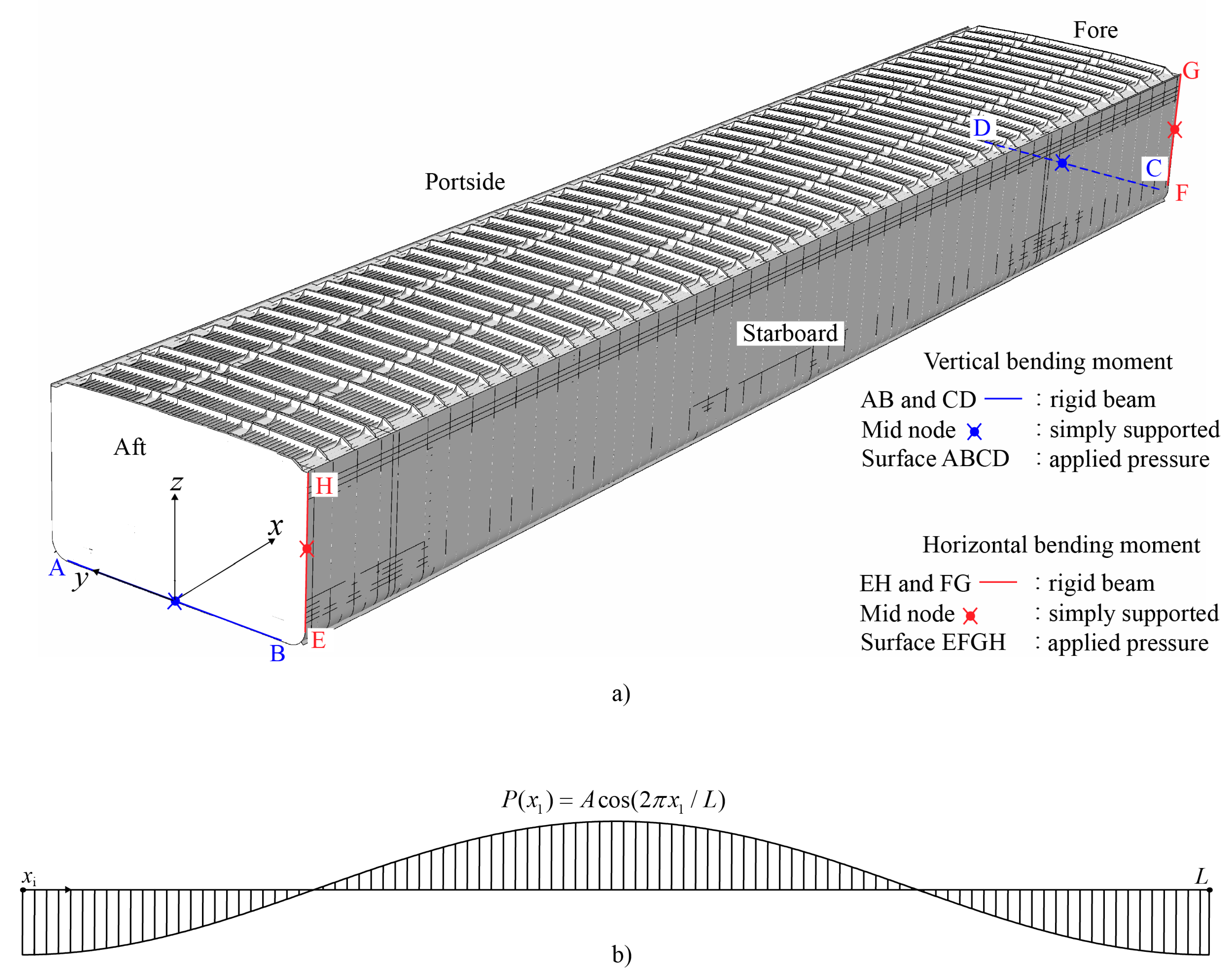
Being a flexible thin-walled beam, the hull girder of the ship flexes globally when exposed to loads. The load components that act on the ship hull girder are the weight of the ship, its cargo, and the hydrostatic and hydrodynamic pressures (external load). The resultant of these load components can be treated with longitudinally distributed load applied on the hull girder, which can increase only by the external pressure due to waves. Therefore, global bending of the ship hull was achieved with longitudinally distributed pressure, which amplitude was gradually increased until ultimate strength was reached. The distributed pressure was applied either on ship bottom or side, depending on whether vertical or horizontal bending moment was determined, respectively. The sinusoidal shape of distributed pressure was kept unchanged during loading, as shown in
Figure 8b. Although, in realistic situations, the distribution of load can play an important role, here only the simplified sinusoidal shape was considered. The direction of bending was controlled by the sign of the pressure amplitude (
A), see the Equation in
Figure 8b. This resulted in sagging/hogging in vertical bending and starboard/portside bending in horizontal bending. In damaged condition, the pressure was not applied in the damage opening. In Abaqus, the VDLOAD subroutine was invoked to apply the distributed pressure.
A simply supported boundary condition was imposed on the ship at the mid nodes marked with •, see
Figure 8a. The aft of the ship was pin constrained with all translations fixed while rotations were free. In the fore part, the constraints were the same except translation in longitudinal direction which was free to avoid an excessive stress concentration during deflection. Furthermore, rigid beams were modeled through the constraint nodes to keep the ends of the beam straight under increasing load and, thus, prevent local buckling. The surfaces where pressure was applied were specified with rectangles ABCD (for vertical bending moment) and EFGH (for horizontal bending moment), see
Figure 8a. The reaction forces on the support is assumed to be very small since the distributed pressures produce the resultant forces of zero.
4.3. Damage Scenario
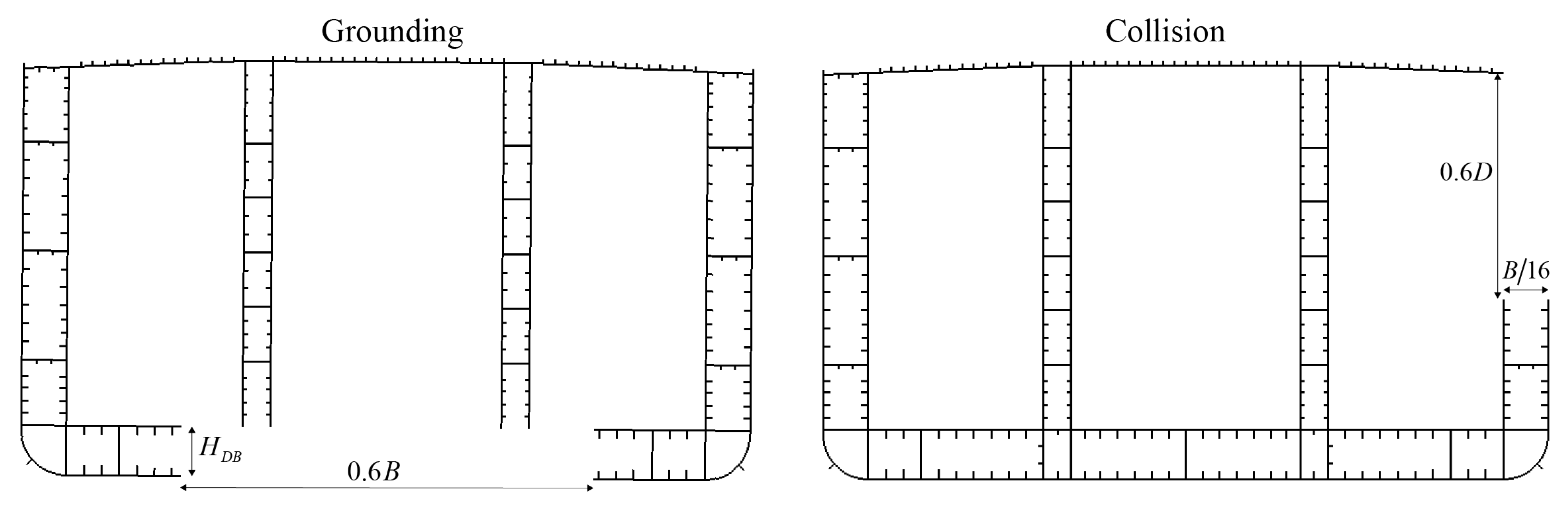
For post-accidental strength assessment of ship structure, both grounding and collision scenarios were considered. The extent of damage was determined based on the definition provided by the IACS-CSR. The damage was modeled by removing the plates, stiffeners, and frames that fall within the specified damage extent. The selected length of damage was 10 m with its center in the middle of the ship. This position was chosen since it significantly reduces the longitudinal bending strength of the ship. In case of collision damage, the transverse damage extent was equal to where B is the breadth of the ship. Therefore, respective structural elements in the parts of inner and outer skin and main deck were removed. The vertical damage extent was taken as measured from the main deck, where D is the depth of the ship.
In case of grounding damage, the transverse damage extent was taken as
, which is symmetric with respect to the centerline. The damage penetration height was equal to the depth of the double bottom (
).
Figure 9 shows the damage extents of the double hull oil tanker for grounding and collision scenario.
4.4. Full 3D Finite Element (3D FE) Model
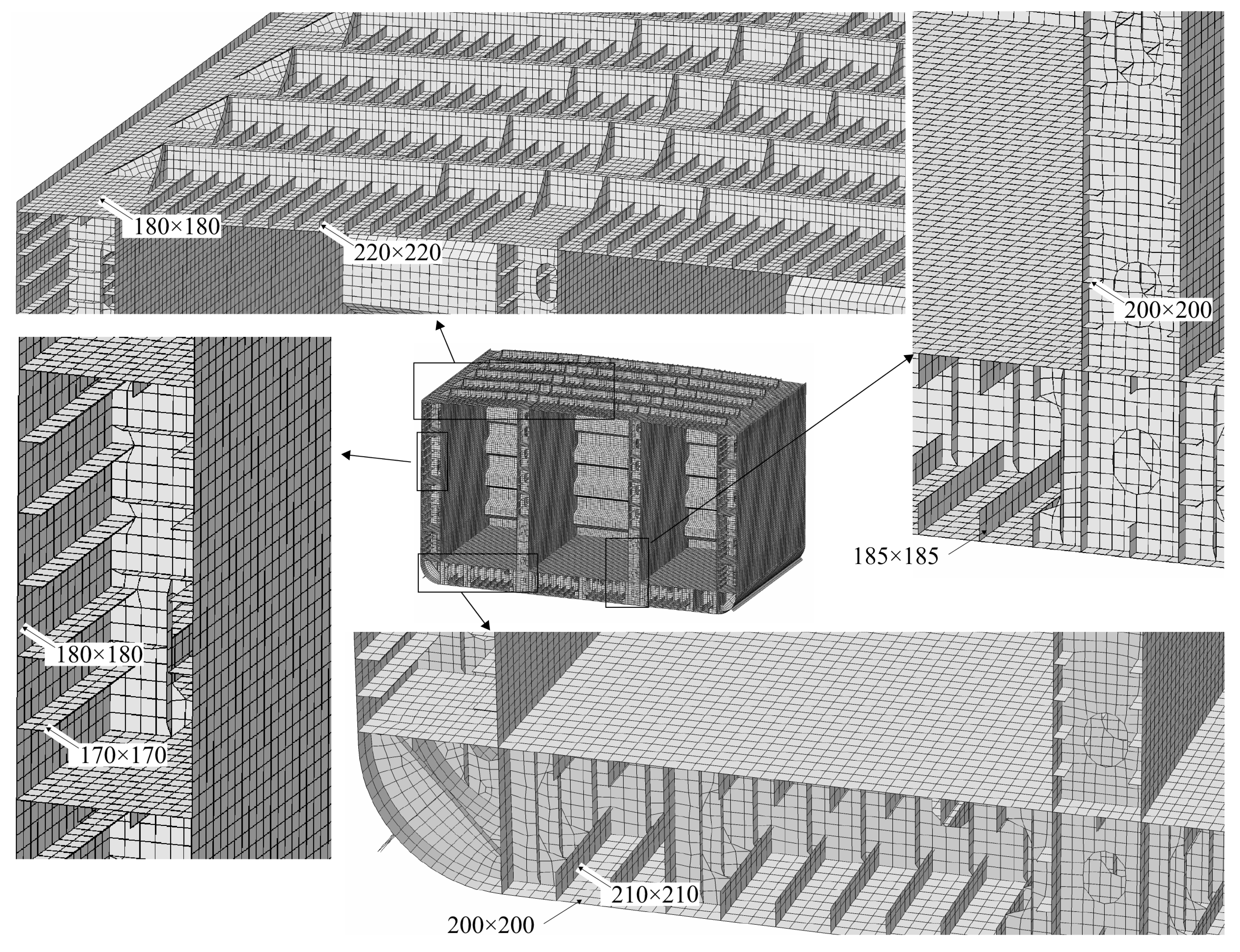
Non-linear finite element method (NLFEM) is a sophisticated tool to solve the solid mechanics problem of complex engineering structures. Using NLFEM, the effect of material and geometrical non-linearities during progressive collapse of hull girder can be taken into account. A chemical tanker was modeled using Abaqus/Explicit software. All models were meshed using four-node shell elements (S4R), including plates, stiffener webs, frames, and girders. Stiffening was achieved with HP bulb profiles where the flanges were modeled using beam elements (B21). Stiffener webs were modeled using shell elements to capture the collapse mode, e.g., local buckling of stiffener web or stiffener tripping, expected during the progressive collapse of the hull girder. The mesh convergence study was conducted by Tabri et al. [
24] to obtain the balance between numerical accuracy and simulation cost. Thus, the mesh density in the one compartment is illustrated in
Figure 10 and can be summarized as follows: (1) plates between longitudinal stiffeners, 4 × 16 shells; (2) stiffener web plates, 1 × 16 (web height < 300 mm) shells and 2 × 16 (web height > 300 mm) shells; (3) side stringers and girders, 12 × 16 shells; and (4) corrugated bulkhead plates, 6 × 40 and 5 × 60 shells. The 3D FE model consisted of 3,160,000 nodes and 2,800,000 elements from which 2.5 M were shell and 0.3 M were beam elements. In the ESL model, stiffeners (shell elements related to web and beam element for flange) were removed so the total number of elements was reduced by 25% to 2,120,000 compared with the full 3D FE model.
4.5. Incremental-Iterative Method
The IACS-CSR provides the incremental-iterative method to calculate the ultimate strength of hull girder. Details of the method are given in CSR, which are briefly summarized here for entirety. The assumption is that hull girder collapse occurs in between two adjacent transverse webs. Accordingly, two-dimensional (2D) cross-section of the ship hull structure is divided into a series of structural elements, such as stiffeners, plates, and hard corners. The response of each of those elements is described with load-end-shortening curve compliant with prevalent collapse mode. Under compression, the stiffener element may experience the specific collapse mode, such as beam-column buckling, torsional buckling, or web buckling. For the plating element, the collapse mode of plate buckling may occur. Other element types under compression or tension may experience idealized elastic-plastic failure. Accordingly, the load-end-shortening curves for each structural element were obtained.
The calculation procedure of ultimate strength starts with estimation of neutral axis (NA) position. The iterative approach involves increasing the assumed curvature of the hull girder and calculating the new position of NA based on the moment equilibrium. Bending moment is obtained by integrating the load over the cross-section, while the load for each element is obtained from the load-end-shortening curves used as input. Once the updated location of the NA is obtained, the curvature is further increased and procedure is repeated until the maximum bending moment is achieved.
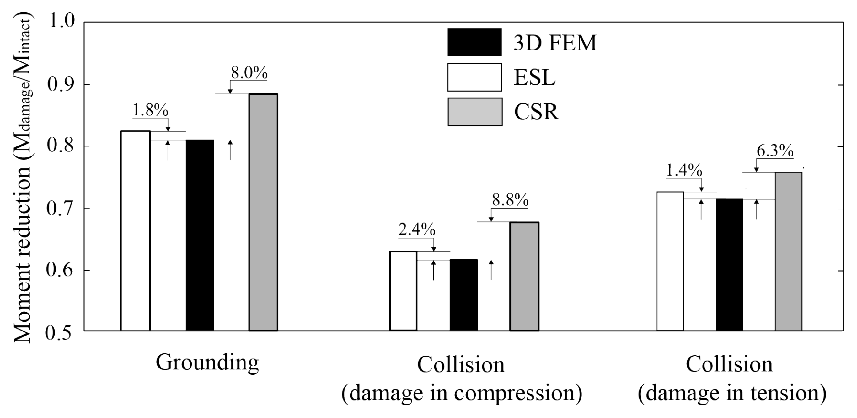
6. Conclusions
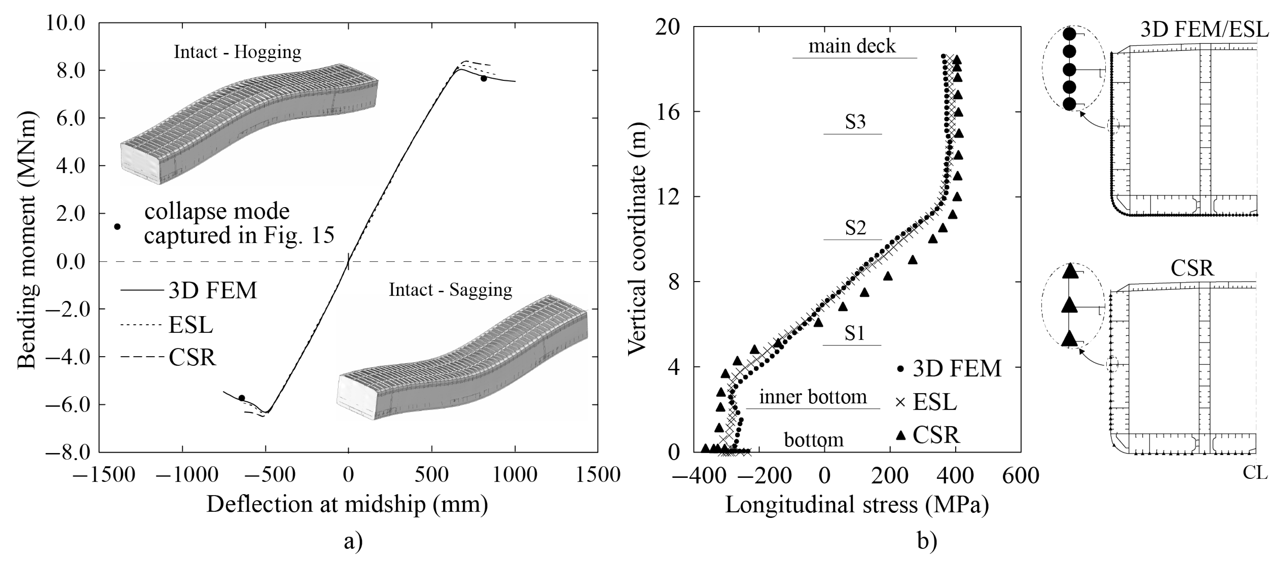
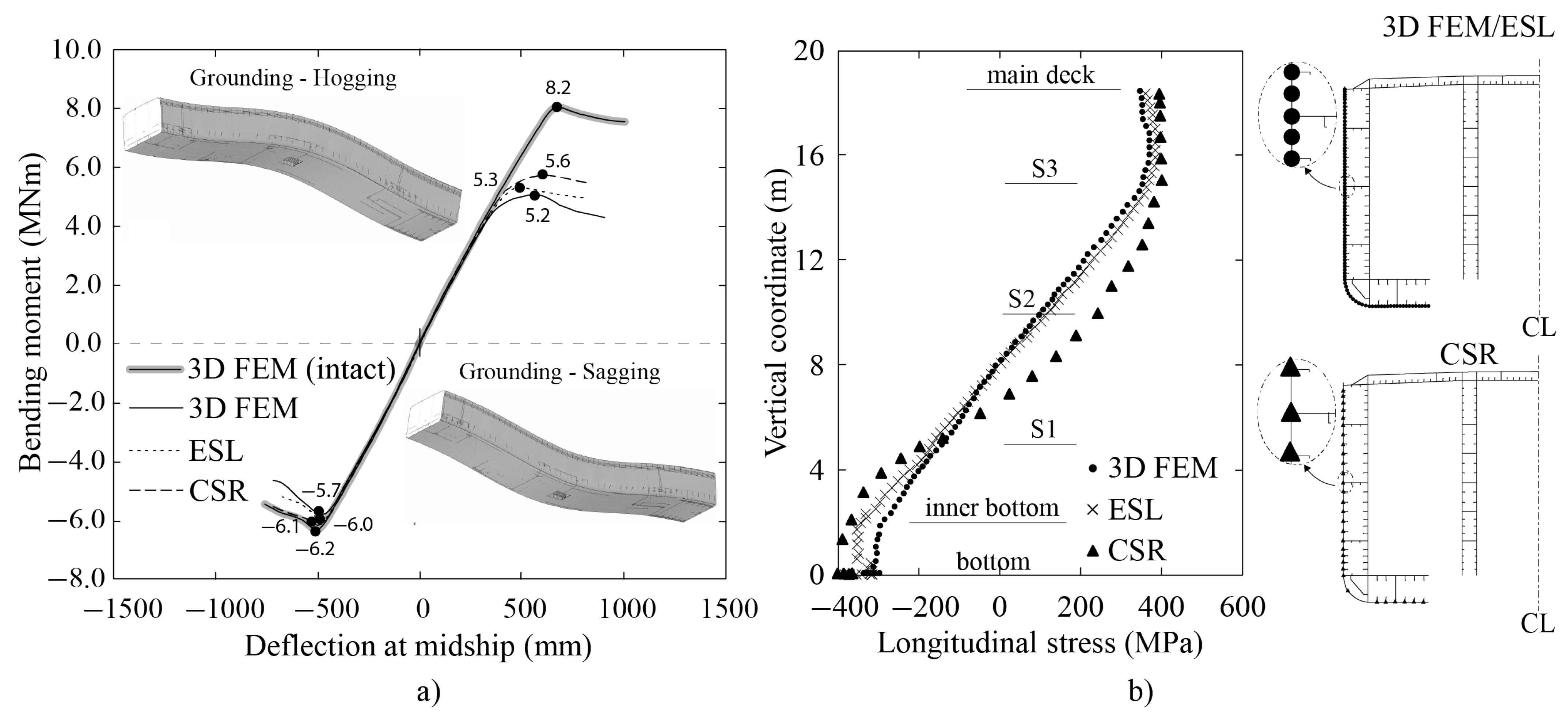
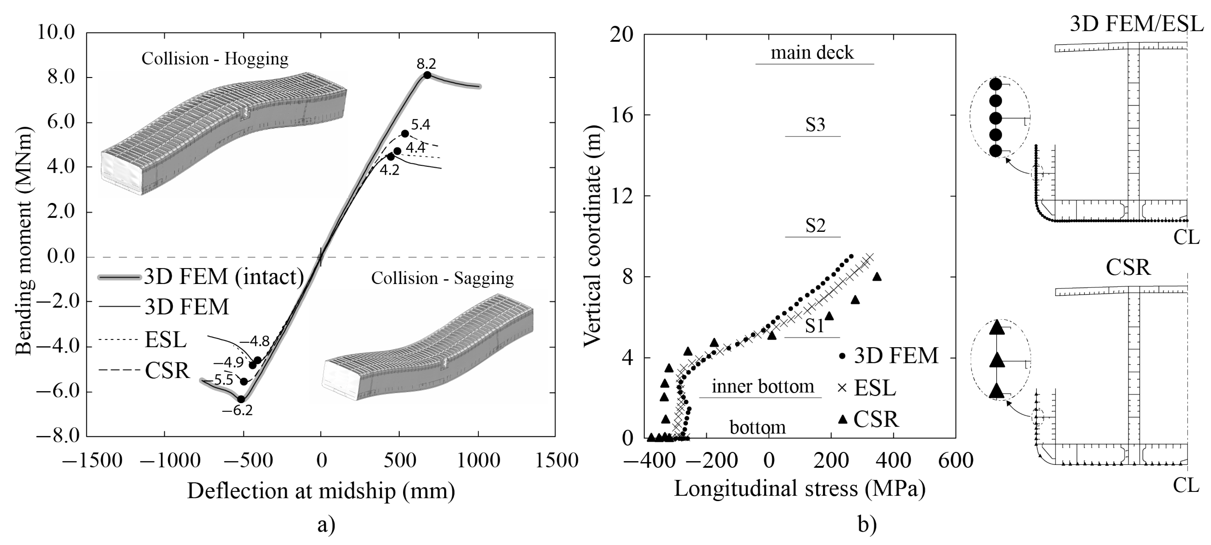
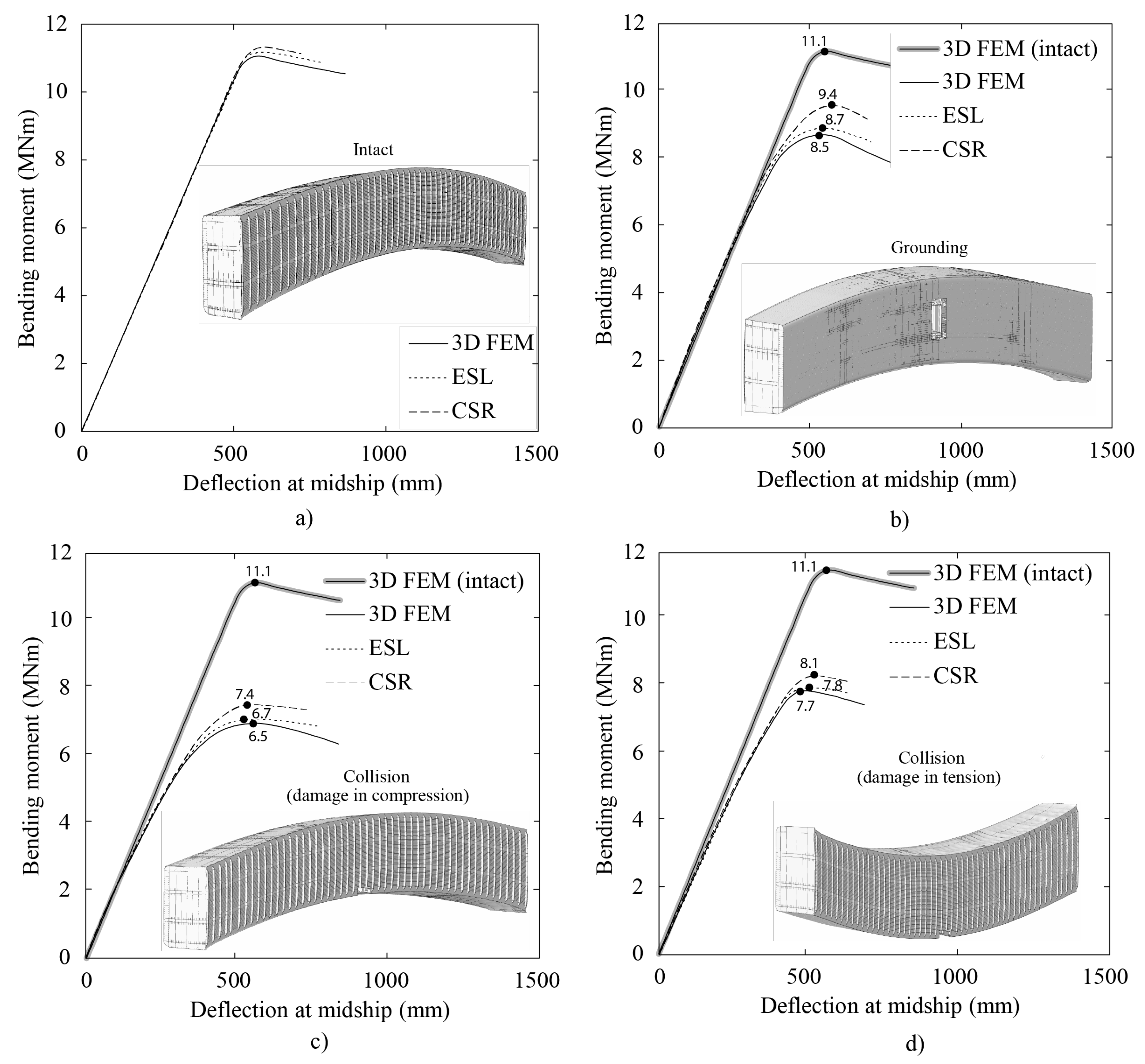
The ultimate strength analyses are carried out using the one compartment and full-scale ship models. The one compartment model is analyzed under vertical bending moment. The full-scale ship model in intact and damaged conditions is analyzed under vertical and horizontal bending moments. The analyses are performed with three methods, namely 3D FEM, ESL, and CSR. Overall, the ultimate strength predicted by the ESL approach give the results close to 3D FEM for all cases.
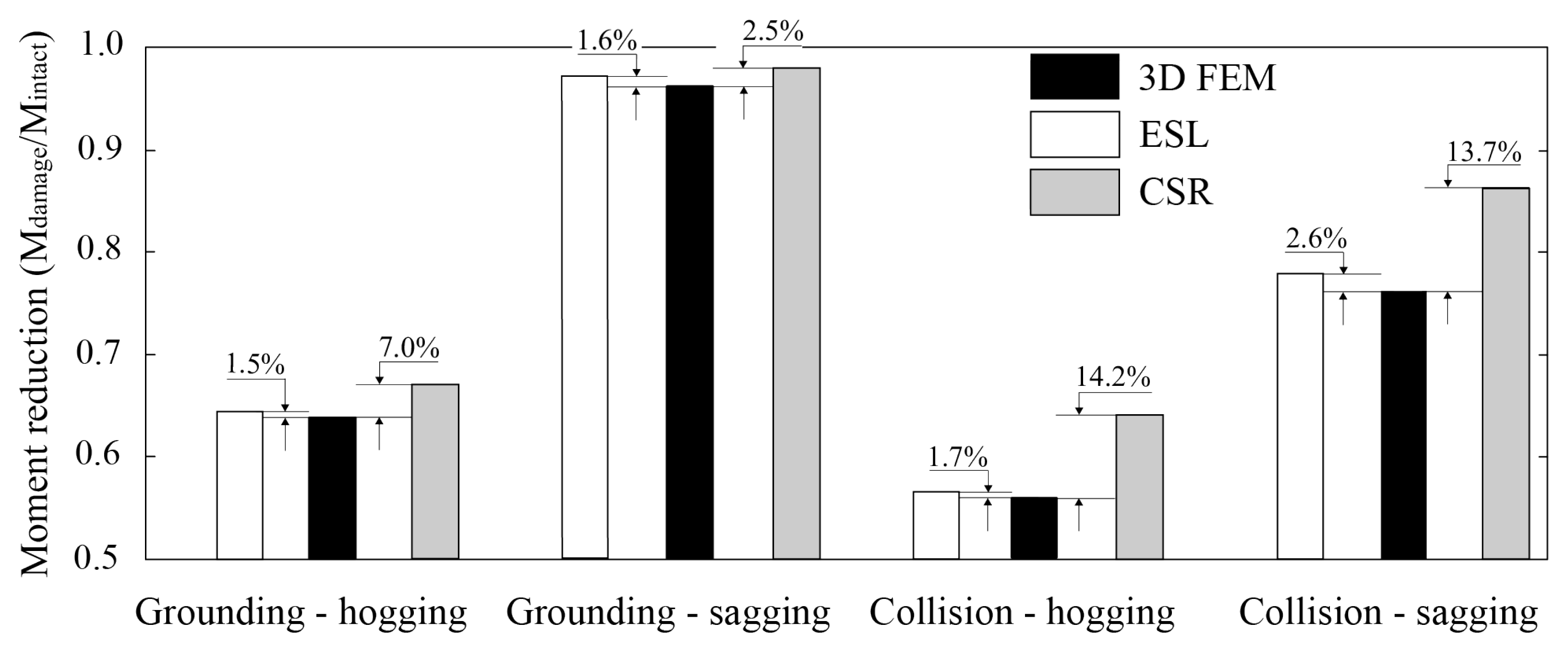
The ESL approach provides a more time-efficient way to analyze the ultimate strength compared to the detailed 3D FEM. In the ESL approach, plate with stiffeners is represented with an equivalent plate with equal stiffness so that stiffeners are not explicitly modeled. This reduces modeling effort as well as computational time and, thus, could be potentially used with great efficiency in structural optimization, which has seen increased popularity due to the advancements in computing power. Current analysis showed that in case of one compartment model, the analysis time was up to 3 times shorter when using the coarsest possible mesh. Moreover, the computational efficiency does not compromise the accuracy as the ultimate bending moment was captured with less than 5% error compared with 3D FEM in all analyzed cases. In contrast, the CSR results overestimate the collapse moment by up to 14.2% in collision damage scenario under hogging. This overestimation of bending moment obtained with CSR method is consistent with analysis in literature, see [
25,
26].
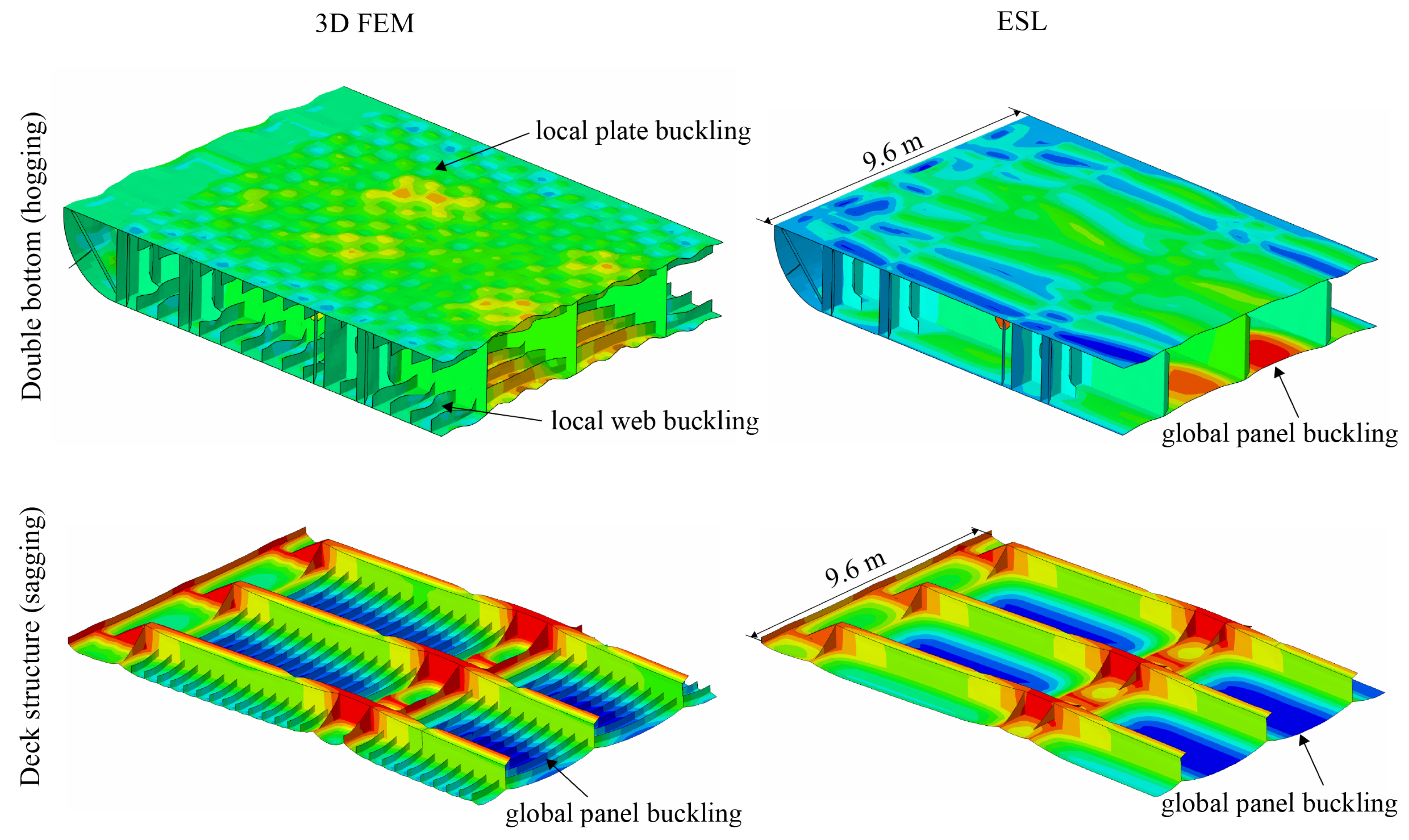
In addition to accurately visualizing the full-scale ship deflection, ESL model can capture the load-response of a ship structure until ultimate bending moment with very good accuracy. However, due to the interaction of structural members, the ESL approach cannot accurately account the local stiffener web buckling collapse in the post-ultimate stage. Furthermore, with ESL methodology one cannot visualize stresses in the post-processing stage. Both aspects need to be addressed in future investigations.


