Article

Efficient Underwater Sensor Data Recovery Method for Real-Time Communication Subsurface Mooring System

1
Institute of Deep-Sea Science and Engineering, Chinese Academy of Sciences, Sanya 572022, China
2
University of Chinese Academy of Sciences, Beijing 100049, China
3
South China Sea Institute of Oceanology, Chinese Academy of Sciences, Guangzhou 510339, China
4
School of Marine Science, SYSU, Zhuhai 519082, China
5
State Key Laboratory of Marine Resource Utilization in South China Sea, Hainan University, Haikou 570228, China
*
Authors to whom correspondence should be addressed.
J. Mar. Sci. Eng. 2022, 10(10), 1491; https://doi.org/10.3390/jmse10101491
Submission received: 28 September 2022 / Revised: 10 October 2022 / Accepted: 11 October 2022 / Published: 14 October 2022
(This article belongs to the Section Ocean Engineering)

Abstract

:
Marine submerged buoys can effectively obtain various parameters of seawater, which plays an important role in the research of marine physical phenomena, marine environmental changes, and climate change. However, traditional self-contained submerged buoys usually work underwater at a depth of about 100 m, and the observation data cannot be obtained before their recovery, which cannot satisfy the needs of real-time data acquisition for marine scientific research. To solve this problem, this paper proposes a real-time communication subsurface mooring system that consists of a satellite communication buoy (SCB), conductivity–temperature–depth sensors (CTD), and an inductive coupling mooring cable. The underwater inductive coupling link collects the data from the underwater sensors and transmit it to the SCB. Then, the data will be transmitted to the station receiver via satellite communication module integrated into the SCB. In order to ensure a high success rate of data recovery, the stress analysis and hydrodynamic simulation of the SCB were carried out in this paper. The results show that the SCB maintained a relatively stable attitude in the 3–4 sea state. The attitude data obtained from the subsequent sea trial was consistent with the simulation results, and the success rate of satellite communication during this period was more than 95%. In this paper, a modular embedded hardware circuit was designed to meet the functional requirements of the subsurface mooring system. An efficient data recovery strategy was also developed, which ensured that the average power consumption of the system was low and the success rate of data recovery is not less than 90% when operating in the severe sea state for a long time. The system underwent sea trials in the South China Sea for more than 3 months from the end of 2021 to the beginning of 2022. It transmitted more than 2034 sets of seawater profile temperature, salinity, and depth data in real-time, with a success rate of over 91% of the total sample data. The CTD data returned in real-time from our system is consistent with the data of the HYCOM and World Ocean Atlas (WOA), and a cyclonic mesoscale eddy was detected in the operation area.

1. Introduction

In 2009, the Ocean Observation Initiative (OOI) observation network program launched by the National Science Foundation of the United States mentioned two real-time submerged communication methods [1]. One transmission method is through submarine cables, which is suitable for near-shore observations [2]. The other operates through the acoustic transmission of an underwater glider, in which the submerged buoy data are transmitted to a glider through an underwater acoustic modem [3]. When the underwater glider floats to the sea surface, the data are transmitted through satellite communication [4], which is suitable for densely distributed submarine buoy arrays. As such, the submerged buoy needs to be equipped with an acoustic modem, which not only consumes a lot of power but also transmits a limited amount of data at a time. This problem makes it difficult to achieve long-term real-time data monitoring.
In addition, the SeaCycler elevating submerged system developed by ODIM Brooke Ocean uses an underwater winch to control the rise and descent movement of the floating communication buoy [5] and periodically releases the float to the water surface for data transmission. Once the transmission is complete, the underwater winch drives the floating buoy below the sea surface. At the same time, WET Labs in the United States and NGK OCEAN in Japan have also developed similar underwater winch platforms [6]. To perform the real-time transmission of underwater monitoring data, the winch installed on the main float is used to control the rise of the floating communication buoy to the sea surface to transmit the underwater observation data to the shore station through satellite communication [7]. The above methods of using underwater winches to achieve real-time communication between submerged targets have the problems of the large volume and complex structures of underwater equipment, which lead to the low reliability of the winch and difficulty of deploying winches at sea.
In addition, the Ocean University of China developed a Timed Communication Buoy System (TCBS) in 2015 [8]. The main underwater float is equipped with multiple ejection-disposable autonomous communication floats (ACFs). The main control of the floating body releases the ACFs to the sea surface for satellite communication according to a set timing. Since it can only be equipped with four ACFs, it usually takes at least dozens of days to release one of them, and hence the data timeliness and long-term in-place ability are poor [9].
In summary, although several real-time communication systems have realized real-time data monitoring, there are still major deficiencies. Underwater gliders are equipped with acoustic relay transmission, which is limited by power and is only suitable for short-term communication. Due to the complex structure of underwater winches, the long-term stability is low, the cost is high, and the deployment process is complex. The number of communication floats that can be carried by the Timed Communication Buoy System is limited, and the timeliness of the data is low. In this paper, we designed a real-time communication subsurface mooring system to solve these deficiencies, which refer to the previous research on satellite communications. Compared with previous studies, this system has the characteristics of strong real-time data transmission, high success rate of data acquisition, and long-term continuous on-position operation.

2. Design of Real-Time Communication Subsurface Mooring System

2.1. General Descriptions of the Real-Time Communication System

The real-time communication subsurface mooring system designed in this paper includes satellite communication buoy (hereinafter referred to as SCB), inductively coupling communication cable [10,11], conductivity–temperature–depth sensors with an inductive modem (CTD-IM) and moorings, as shown in Figure 1. For the operation of the system, the SCB on the sea surface collects various types of sensor data through the underwater inductive coupling cable [12], and the minimum collection interval is around 3 min. Then, the data will be verified, compressed, and encrypted through the processing unit, and finally transmitted to the shore station receiver through satellite communication, so as to achieve the purpose of real-time acquisition of underwater sensor data [13]. Because of the two-way communication function of the SCB, the shore station receiver can complete the operations of querying the status of the SCB and underwater sensor, changing the sampling mode, and returning historical data by remotely issuing commands.

2.2. Hydrodynamic Analysis of SCB

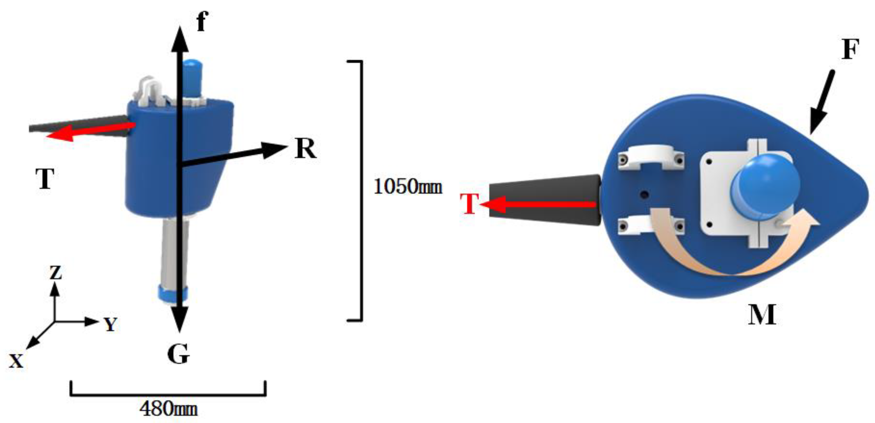
The SCB is affected by the marine environment, such as currents, tides, wind, waves, and other elements during the monitoring process, which cause attitude changes such as rotation, pitch, tilt, etc. The SCB integrates the satellite communication module, and the communication effect is directly affected by the attitude. When the swaying angle of the SCB increases, the failure rate of the satellite communication increases, which has a serious impact on the timeliness of the observation data from underwater sensors [14]. At the same time, in order to improve the concealment of the SCB and reduce the risk of its destruction, its size should be minimized. The design of the SCB is shown in Figure 2. Its unique shape structure reduces the impact of ocean currents and waves. At the same time, under the comprehensive action of the gravity, the buoyancy, and the pulling force from the mooring cable, the SCB above water is relatively stable, and the water outlet height is moderate. To verify the design effect, the force analysis and numerical simulation analysis of the SCB under the influence of waves were carried out as follows.
According to the hydrostatic posture of the SCB along with numerical analysis, the coordinate system shown in Figure 2 was established. The X axis is defined as the front and rear direction of the SCB. The Y axis and the X axis are in the horizontal plane, and the Z axis is perpendicular to the X-Y plane and pointing upward, as shown in the coordinate system in Figure 2. The origin is the center of gravity of the SCB, the rotation around the X axis is defined as the inclination angle (also known as the roll), the rotation around the Y axis is defined as the pitch angle (pitch), and the rotation around the Z axis is defined as the azimuth angle (also known as the yaw) [15].
The SCB is subjected to gravity G, buoyancy f, steel cable pulling force T, fluid force R, the restoring moment M under the steel cable and the side surface of the SCB when it rotates received resistance F. Since the cross-section is an airfoil, the azimuth change of the SCB is mainly affected by the action of the wind, waves, and ocean currents [16]. Due to the pulling force of the steel cable in the X direction, the pitch angle of the rotation around the Y axis is small. The change in the azimuth angle hardly affects satellite communication, while the inclination angle around the X axis changes greatly, which has significant influence on satellite communication.
A computed numerical simulation analysis was carried out for the structure of the SCB [17]. The SCB was subjected to a four-level sea state with a wave height of 1.2 m and a period of 5 s; the attitude and motion simulation of the surface velocity required 1.5 m/s to establish a connection with SCB and the current and wave. The simulation model is shown in Figure 3.
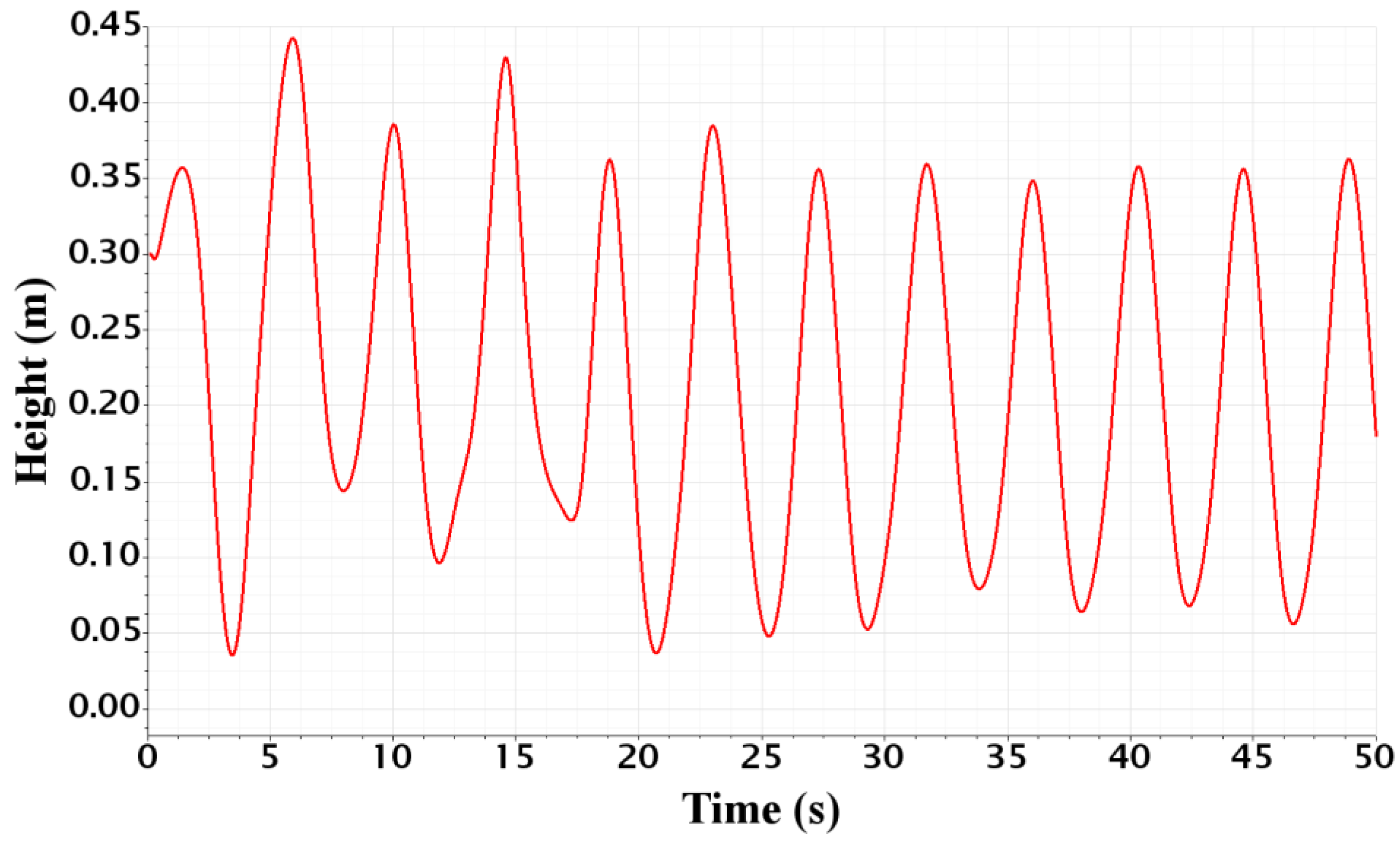
In the initial state, the SCB was suspended on the sea surface and the satellite antenna height from the sea surface was about 0.25 m. Under the influence of ocean currents and waves, the SCB was affected by the external force of the fluid, which leads to a posture and position variation and performed heave and pitch motions with the waves and ocean currents. Figure 4 shows the height changes of the satellite antenna above the sea surface within 50 s. The maximum value was 0.44 m and the minimum was 0.04 m. This shows that under the action of ocean waves, the SCB will instantly sink under the sea surface for a very short period, and then rise to the sea surface under the action of its buoyancy.
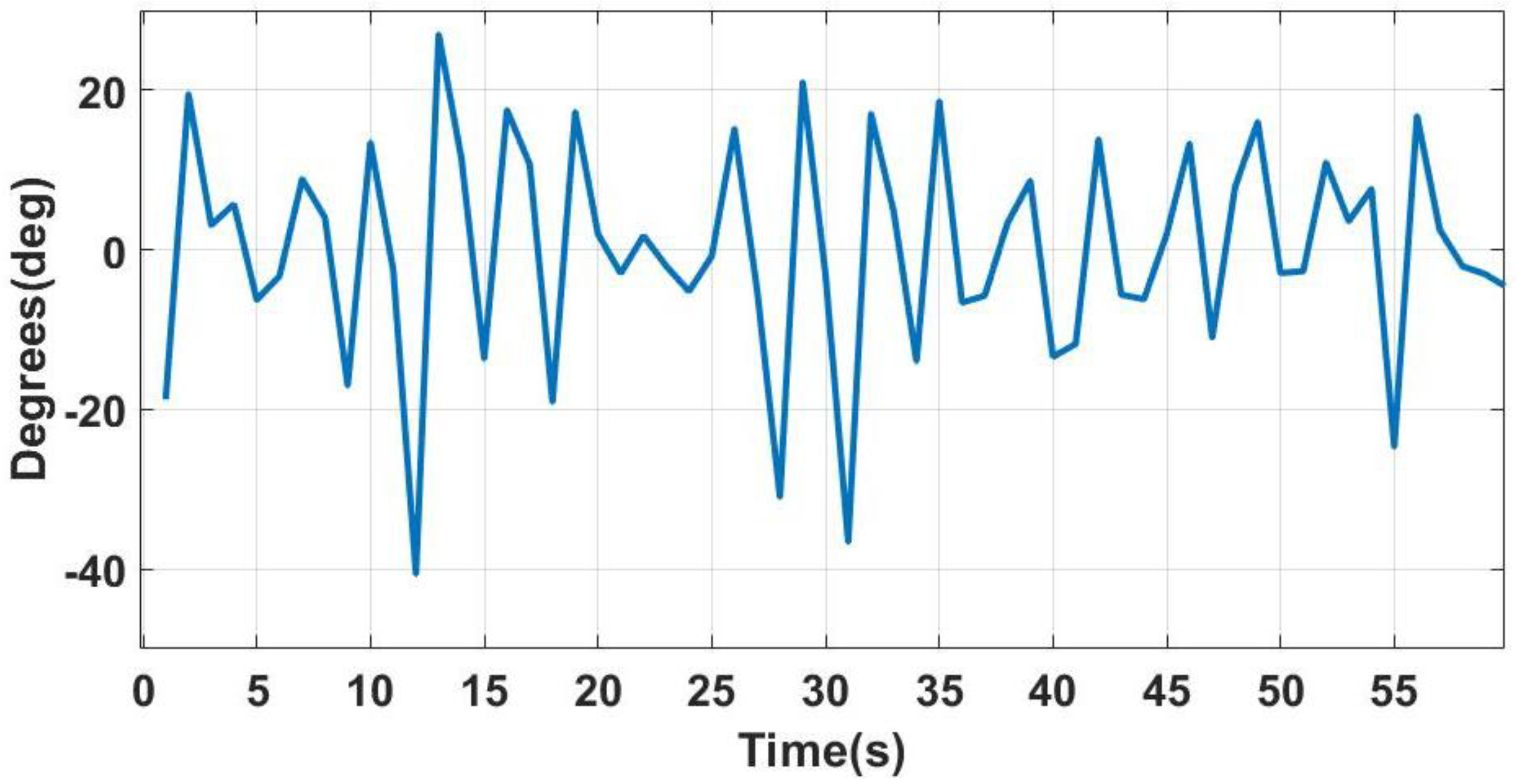
Figure 4 shows that under a harsh sea state, the water outlet height of the SCB was above 0.25 m for nearly half of the total time, and the water outlet height was above 0.1 m for more than 90% of the time. As shown in Figure 5, the inclination angle of the SCB changed periodically in the range of −25°~20°, and the variation period was about 4 s [18]. The test results show that the communication of the satellite module was normal when the swing angle was less than 30° in a non-occluded environment [19,20]. Therefore, as can be seen in the simulation results, the SCB realized real-time data transmission under the condition of no higher than the fourth-level sea state.
In order to verify the effectiveness of the above simulation analysis of the SCB, the sea trial was carried out in the sea near Hainan Island, and the sea state during the offshore sea trial was about level 3–4, which was close to the above simulation environment conditions. As shown in Figure 6, the tiltmeter sensor was installed at the center of gravity of the SCB and kept parallel to it. The tiltmeter used the MAT-1 Data Logger from Lowell Instruments, which contains an integrated three-axis magnetometer and three-axis accelerometer. Through the coordinate transformation, the varied history of the SCB could be obtained by recording the three-axis angle value through the sensor data with the sampling frequency set at 1 Hz.
Figure 7 shows that the inclination angle of SCB changes within 60 s. The swing period of the SCB under the influence of the wind and waves was 4 s with an average change amplitude of 18°. The average maximum inclination angle was 20°, and the inclination angle mostly varies periodically from −25° to 20°, which was consistent with the change period and maximum inclination angle of the SCB in the numerical simulation results.
During this test, the real-time communication subsurface mooring system was deployed about 42 h, and the data return interval was 15 min. During the experiment, the SCB should have transmitted168 data packets, while the final number of data packets received by the shore station was 160. The success rate of the data transmission was over 95%. A preliminary analysis found that the period of data packet loss was concentrated between 1:00 and 6:00 on the second day. During this period, the SCB was affected by the severe sea state at night, which increased the inclination angle and reduced the water outlet height, causing the success rate of the data transmission to be slightly reduced.
In summary, by comparing the simulation results of the SCB with the sea trial results, it was found that the motion data variation of the SCB was consistent, which verified the correctness of the simulation results. The sea trial results show that the SCB could maintain a relatively stable attitude and water exit height under the severe sea state. This indicates the stable and reliable transmission of the submerged sensors data, and the communication success rate exceeded 95%. Combined with the above numerical simulation and sea trial results, the structural shape of the SCB can be further optimized to reduce its swing angle, increase the water outlet height of the antenna, improve the ability of the SCB body to resist wind and waves, and further improve the data transmission stability during long-term operation.

2.3. System Hardware Circuit Design

2.3.1. Satellite Communication Buoy (SCB)

The function of the SCB is to establish a complete data communication link between the underwater sensor and the receiver at the ground station, so as to realize the collection and real-time recording of data, and to make remote modifications by receiving instructions from the shore station and adjust the working parameters of the system. The SCB is mainly composed of the main control unit, the battery unit, and a floating buoy of a specific shape, as shown in Figure 1 and Figure 2. Its overall size is small, but its unique shape and structure design improves the stability of attitude. The main control unit includes circuit modules such as the satellite communication module to realize the functions of sensor data acquisition, processing, and real-time transmission. The battery unit is equipped with lithium battery packs to provide energy. The nominal voltage of the battery pack is 11 V and effective capacity is 1544.4 Wh, which can support the system for more than 1 year.
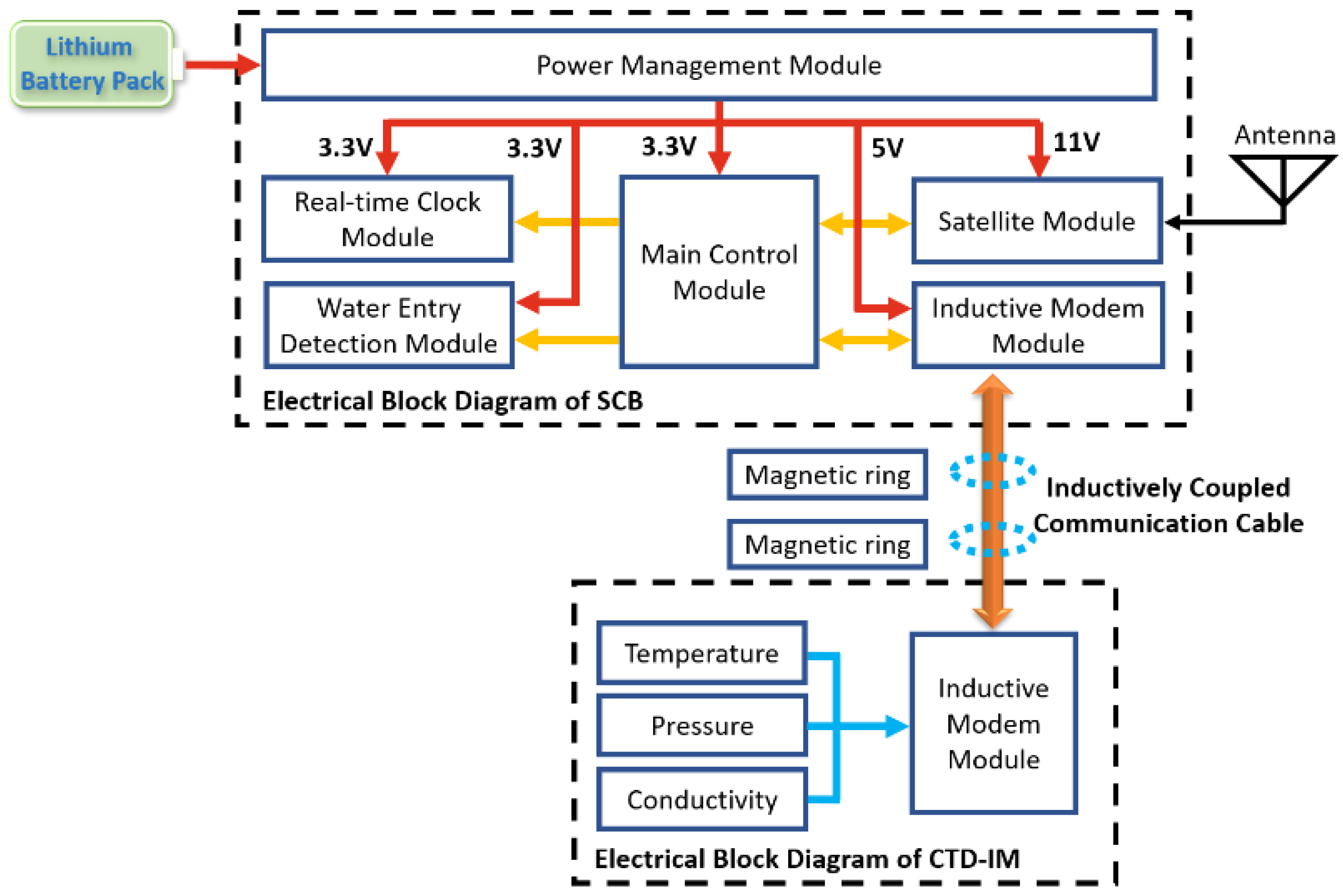
As shown in Figure 8, the main control unit of the SCB consists of the control module, the real-time clock module, the data acquisition module, the power management module, the satellite communication module, and the water entry detection module. The control module uses a 16-bit MSP430 microcontroller to set the program logic to control other modules to implement various workflows of the system and verify, compress, and encrypt sensor data. We used a programmable real-time clock chip to provide the system with a high-precision calendar function and timing function and also use an external temperature-compensated crystal oscillator to improve the travel time accuracy, which can ensure that in the temperature range from 0 to 50 °C, the annual drift of the clock is less than ±40 s. The data acquisition module integrates the inductive modem module [21], which can collect the sensor data according to the set logic and store them in the FLASH memory chip after verifying its effectiveness. It can store no less than 10,000 sets of sensor data, which stores about 416 days of data. The power management module uses the DC–DC and LDO circuits to convert the power supply voltage and provide it to other modules through the analog switch. The satellite communication module selects the Beidou second-generation module with the short message mode for data transmission [22]. Since a single Beidou card can only transmit 70 bytes of data each time in the short message mode, this system was designed with a multi-card polling transmission mode to increase the communication bandwidth. The water entry detection module uses the double-electrode detection method to detect whether the SCB is on the sea surface. Two electrodes are installed on the outer wall of the control cabin. When the SCB is below the sea surface, the electrodes are turned on. Otherwise, the electrodes are disconnected. It provides a reference for an efficient decision data recovery strategy.

2.3.2. Conductivity–Temperature–Depth Sensor (CTD)

The conductivity–temperature–depth sensors with an inductive modem (CTD-IM, TD-IM) developed by the Institute of Deep-Sea Science and Engineering, Chinese Academy of Sciences, were unitized in this system. Taking CTD-IM as an example, it has the function of inductive coupling communication and can collect three parameters including temperature, pressure, and conductivity. The measurement depth can reach 7000 m with high measurement accuracy and small long-term drift. The temperature sensor uses a negative temperature coefficient thermistor as the sensing element, and the proportional measurement method is used to measure the value with an accuracy of ±0.002 °C [23]. The pressure measurement uses an oil-filled pressure probe of MEMS technology [24,25], and the internal measurement network can be simplified into a set of Wheatstone bridges, combined with a constant current source excitation circuit with extremely low-temperature drift and external compensation resistance. The accuracy of the pressure measurement can reach up as ±0.03% F.S. The conductivity is measured through the seven-electrode method, and the high-precision signal acquisition and processing circuit are designed to reach an accuracy of around ±0.003 mS/cm [26].

2.4. System Software Design

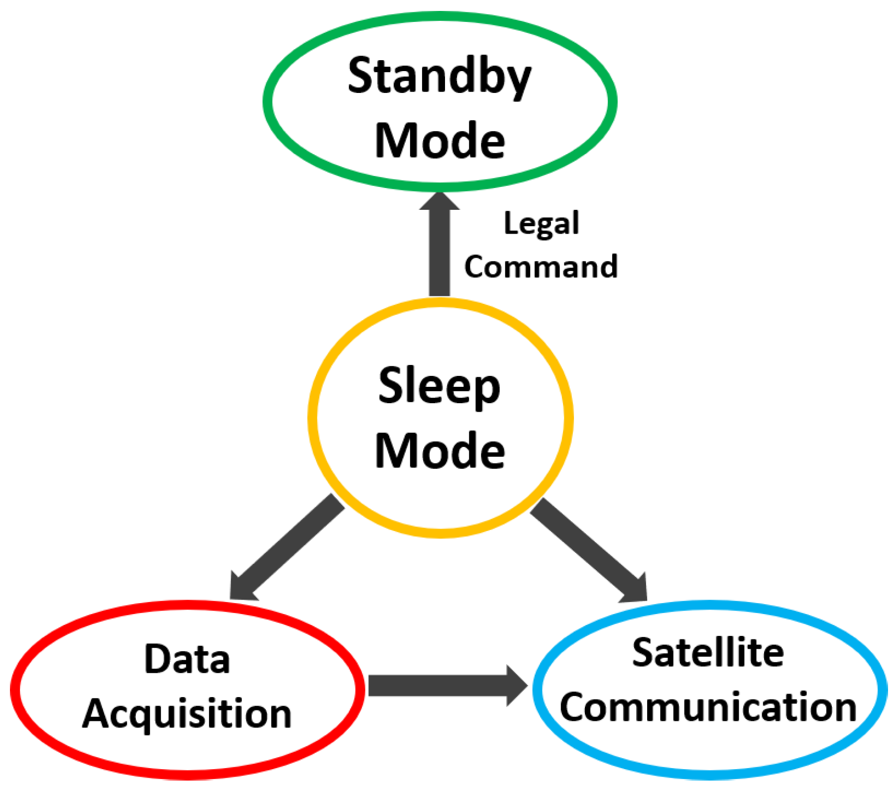
The software of the real-time communication subsurface mooring system is designed with a state machine architecture divided into four working states: sleep, standby, data acquisition, and satellite communication according to its workflow, as shown in Figure 9. The system is in a sleep state most of the time; the main control circuit board will be in sleep mode at this time, most peripherals are in the power-off state, and the power consumption of the whole machine architecture can be reduced to about 60uA@11V. When the system serial port receives a legal command, it will move to the standby state; various working parameters of the system can be configured at this time. During the data acquisition state, the inductive modem module will poll and collect all sensor info and also verify and compress the data [27]. After the acquisition is completed, it will enter into the satellite communication state immediately; during this process, the system will enable the satellite communication module to encapsulate and encrypt the current coordinates and sensor data and transmit them to the ground station. This system can also directly enter the satellite communication state at the set period of each day. At the same time, the system can remotely receive instructions from the shore station and complete operations such as status query, parameter modification, and historical data reissue.

3. Efficient Data Recovery Strategy Design

We designed a low-power and high-efficiency data backhaul strategy to ensure that the success rate of data backhaul is not less than 90% when the system is in a complex and changeable marine environment for a long site operation. The SCB is affected by weather and the sea state. A bad sea state and strong surface currents will impact the stability of data acquisition and transmission, and the SCB will sink below the sea surface, which will greatly reduce the success rate of satellite communication. Increasing the number of satellite communications in that scenario has a small effect on the system but at the same time will cause a large increase in the system’s power consumption, which cannot meet the long-term on-site work requirements. If the battery capacity increases, the volume of the SCB will follow, the concealment will decrease, and the overall cost will increase.
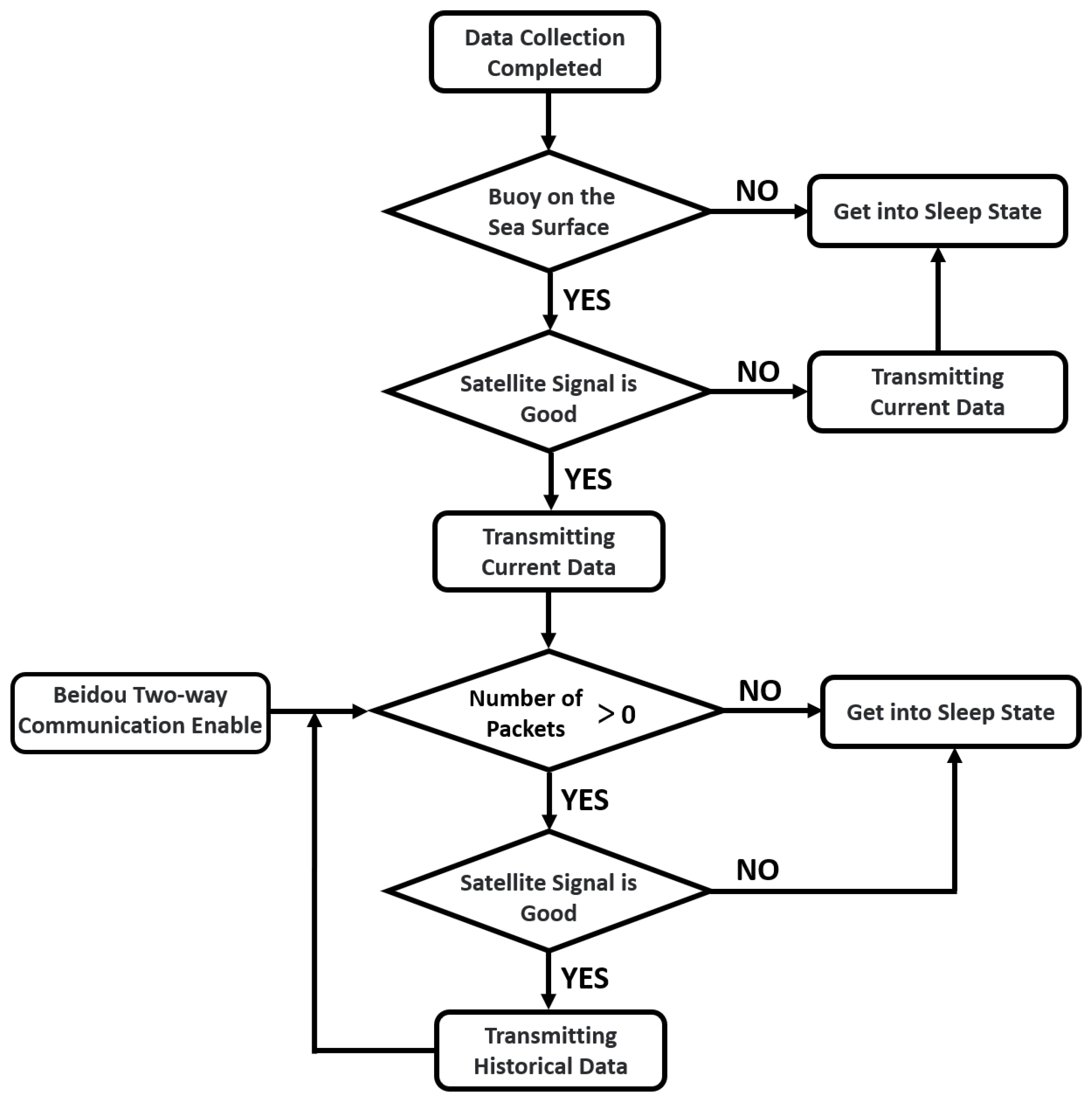
In order to meet the long-term working requirements and ensure high-efficiency data return based on the hardware functions of this system, we designed a low-power-efficient decision data recovery strategy. The algorithm logic flow is shown in Figure 10. After the system performs the data collection operation, it will move to the satellite communication state. At this time, the water entry detection function is used to detect the current state of the SCB. If it is detected that the SCB is below the sea surface, the current packets will be marked as historical data and stored for subsequent re-send operations, which is followed immediately by the sleep state to wait for the next data collection to start. If the SCB is on the sea surface, the current signal quality will be detected by the satellite module. If the signal quality is low, it means that the system will try to return the current data packet and directly enter the sleep state. If the signal quality is good, the current data packet will be transmitted first. Then if there is a historical data packet, the re-send operations will be performed in order. During this period, the signal quality of the satellite module will be monitored. If the signal quality becomes poor, the system will stop data retransmission and enter the sleep state. In addition, the system can also enable the satellite to perform two-way communication at a set period every day. During this period, the SCB can receive commands from the receiver at the ground station and perform historical data reissue operations. The ground station operator can check the weather, current, and wave parameters of the sea area where the system is located and select a period with a good sea state to enable two-way satellite communication. At this time, the success rate of satellite communication will be greatly improved and the efficiency of historical data reissue will be guaranteed. Through the above-mentioned SCB status detection, satellite communication quality detection and historical data reissue strategy, the data return efficiency of this system will be significantly improved, the average power consumption will be effectively reduced, and the long-term on-site working ability will be greatly enhanced.

4. Sea Experiment

In order to verify the performance of the real-time communication subsurface mooring system during long-term operation, from 15 December 2021 to 18 March 2022, a sea experiment was carried out in an area near Xisha, China. The deployment point was located at the coordinates 113° E, 19° N, with a water depth of up to 1165 m. The total length of the real-time communication subsurface mooring system was 1220 m. As shown in Figure 11, the top of the system was the SCB, which was integrated with the Beidou second-generation satellite module, and the communication rate reached up to 400 Byte/min. The data return frequency was 1 h/time in this test. The SCB was connected with the inductive coupling cable, and the length of the cable was 650 m. The cable was equipped with 15 sensors, include 12 TD-IM and 3 CTD-IM. Due to the dramatic changes in the temperature and salinity data of the sea surface thermocline, five TD-IMs and three CTD-IMs were installed on the inductive coupling cable with a water depth from 40 m to 110 m. Four TD-IMs were installed on the inductive coupling cable with a water depth of 200 m to 500 m. Table 1 shows the estimated operating depth of each sensor. The lower end of the inductive coupling cable was connected to the mooring device with a total length of about 570 m. The mooring device consisted of a glass float, a Kevlar rope, a parallel acoustic release, and an anchor. The real-time communication subsurface mooring system was deployed for 93 days, and 2034 sets of CTD data have been successfully returned, of which 1489 sets of data were sent back immediately after sampling, and 545 sets of data were successfully re-issued through the efficient decision data recovery strategy; the data return success rate was 91.1%.
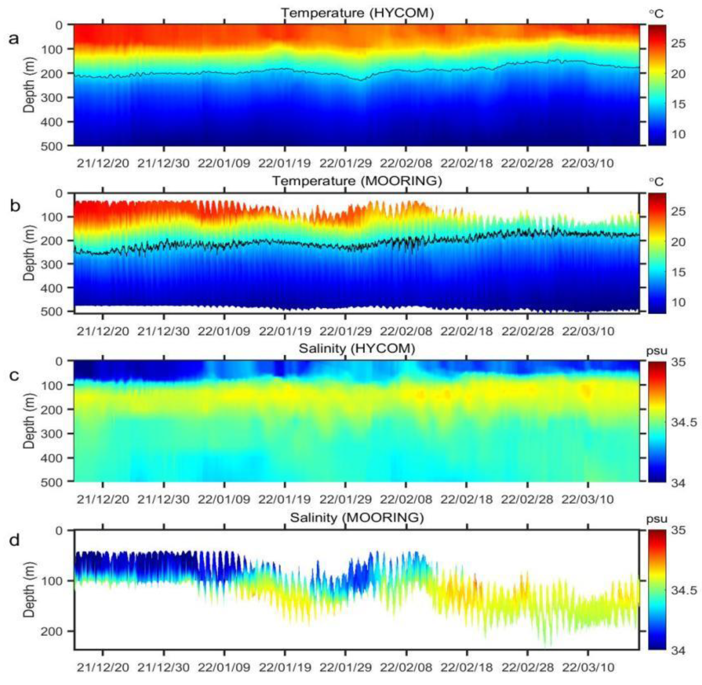
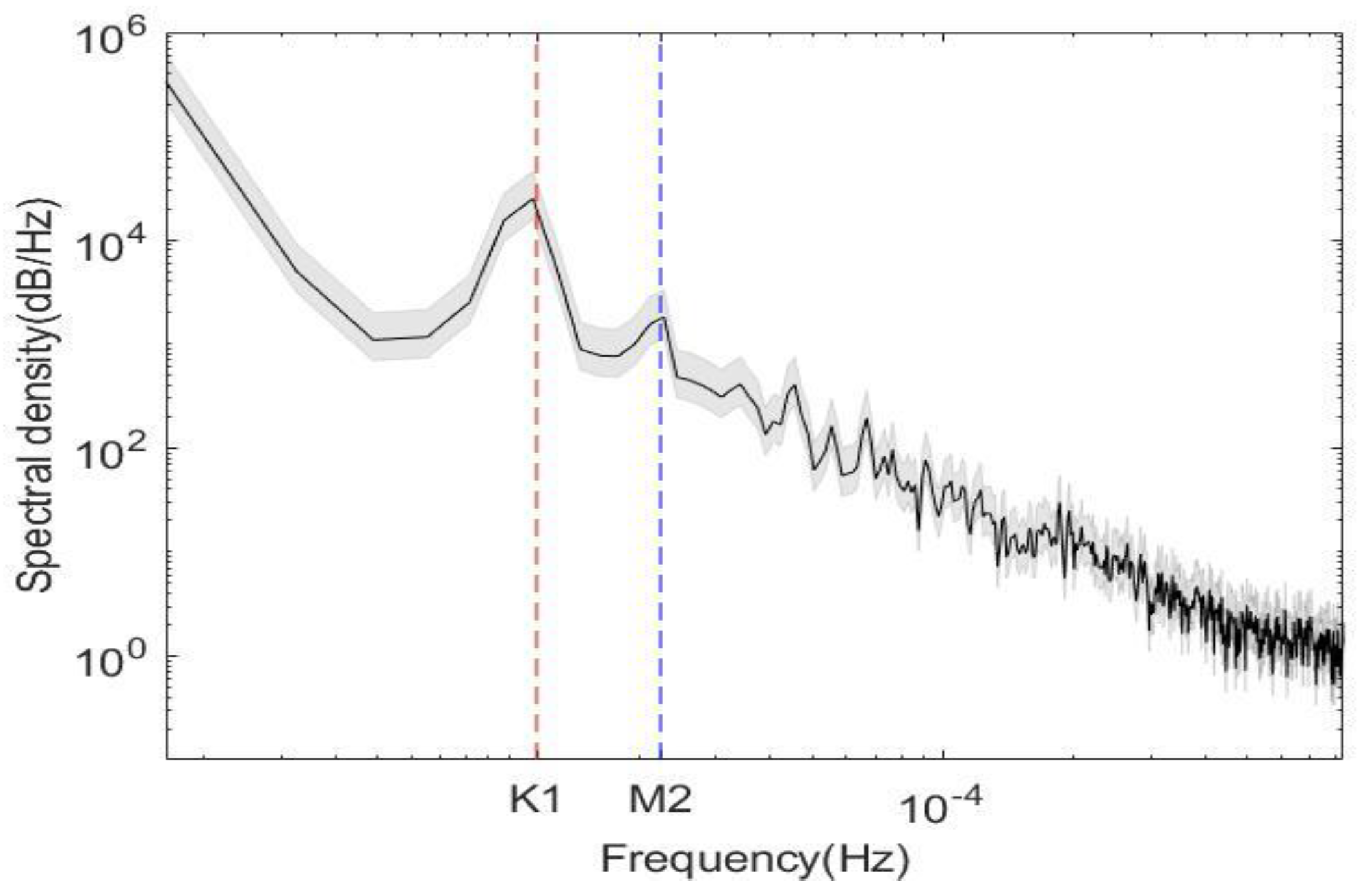
The temperature and salinity profiles from the in situ observations match excellently with those from the HYbrid Coordinate Ocean Model (HYCOM) output (https://www.hycom.org/dataserver/gofs-3pt1/reanalysis, accessed on 5 September 2022) and more detailed information because of the high sampling frequency of the CTD. The temperature profiles from the CTD observations and the HYCOM output are illustrated in Figure 12a,b, and both 15℃ isotherms show an upward trend with time. The salinity profiles from the CTD observations and the HYCOM output are illustrated in Figure 12c,d, and both profiles revealed that the maximum salinity is in the subsurface layer. The salinity also shows an upward trend between February 29 and March 15. In addition to the entire uplift of the isotherm, the temperature and salinity profiles have an obvious fluctuating signal. The power spectrum of the density variety has the obvious distribution of internal tide energy (Figure 13). As shown in Figure 13, the diurnal (mainly K1) and semi-diurnal (mainly M2) peaks are remarkable, and this is consistent with the results of the velocity spectrum of previous studies [28,29].
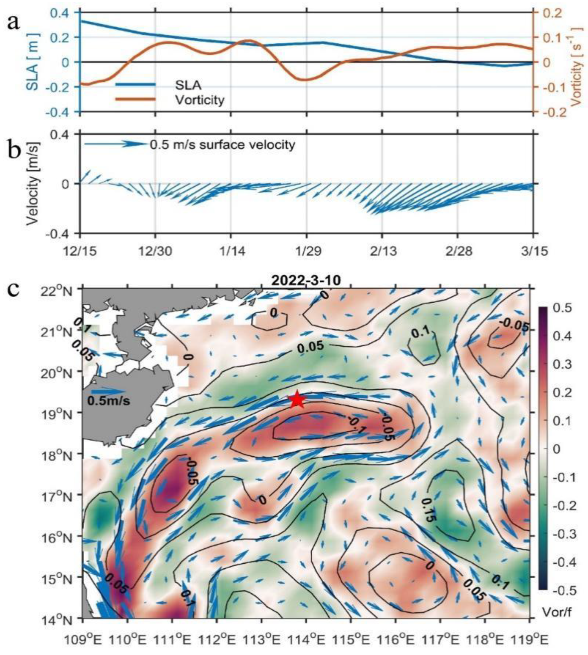
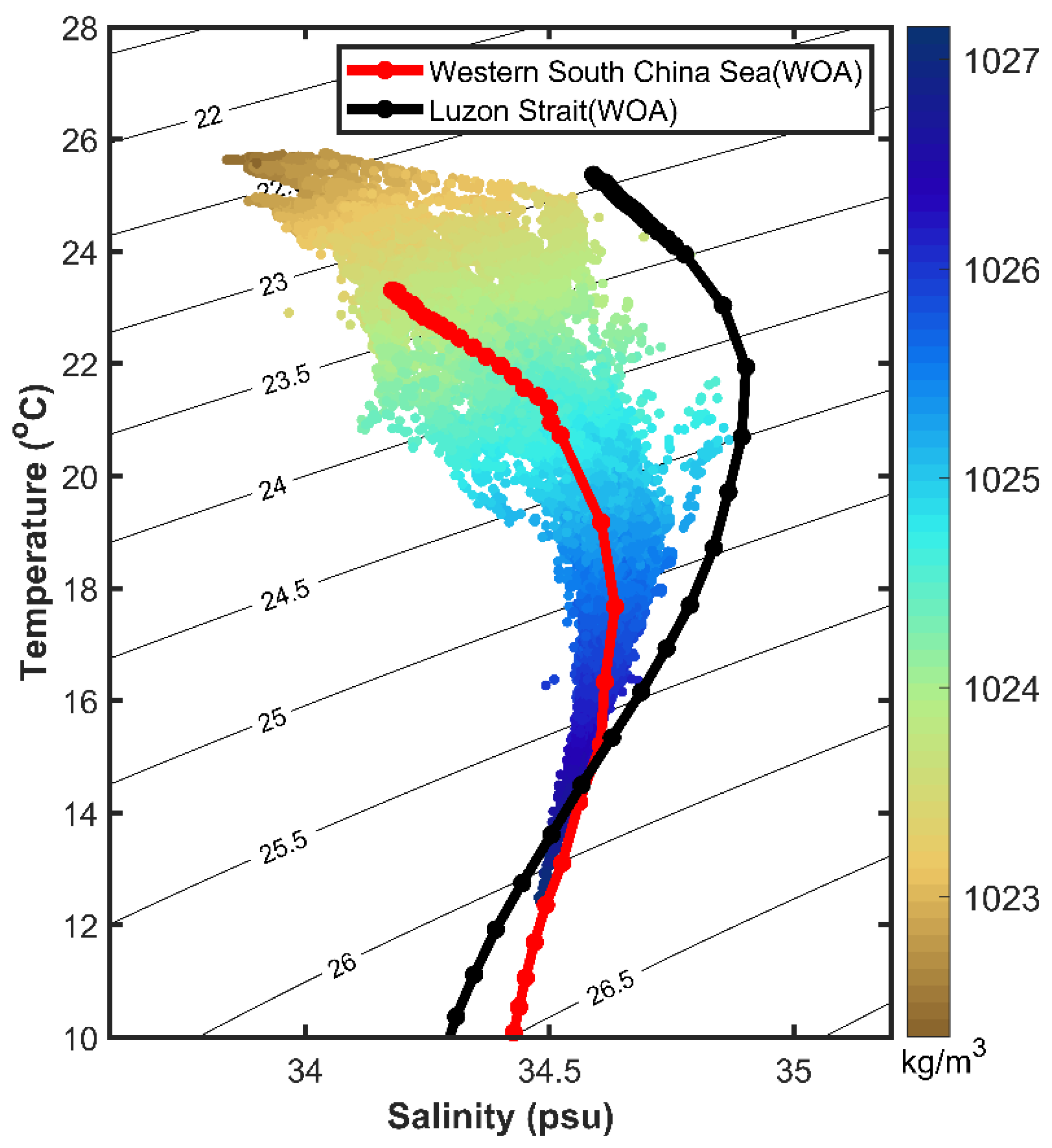
According to the sea level anomaly maps obtained from the Copernicus Marine and Environment Monitoring Service (https://doi.org/10.48670/moi-00148), the entire uplift of the isotherm revealed the movement of a cyclonic mesoscale eddy passing by the mooring site (Figure 14), and our moored CTD observed precisely the thermohaline structure of this process beneath the surface. The satellite maps show that the cyclonic mesoscale eddy was generated east side of the mooring. Although the cyclonic mesoscale eddy moved southwest during our observation period, the mooring was always located within the northern margin of the cyclonic eddy (Figure 14c). The surface current velocity at the mooring site remained southwestward, and the maximum velocity reached 0.5 m/s on February 17 (Figure 14b). As the cyclonic eddy moved toward the southwest, the sea level anomaly at the mooring site decreased slowly through zeros on February 18. Most cyclonic mesoscale eddies have an upward temperature dome below the mixed layer [30,31]. Therefore, the upward isotherms in the mooring observations were caused by the horizontal movement of the cyclonic eddy. This cyclonic mesoscale eddy was captured by our mooring profile in the southwest region of the South China Sea (SCS), providing a good method of studying their water mass characteristics. Firstly, we compared the T-S characteristics between the western SCS’s and the Luson Strait’s water (Figure 15). The notable difference between these two water masses is that the Luson Strait’s water is warmer and saltier in the upper layer. We also compared the T-S values within the cyclonic mesoscale eddy obtained from the moored CTD data (Figure 15 scatter). In the upper layer, the water within the cyclonic mesoscale eddy showed T-S properties close to the western SCS. These result verify that this cyclonic mesoscale eddy was locally generated in the SCS rather than from the Luson Strait. The results of our moored CTD data coincides with those from the World Ocean Atlas (WOA) data (https://www.ncei.noaa.gov/access/world-ocean-atlas-2018/bin/woa18.pl) and characterize the real thermohaline structure of the SCS.

5. Conclusions

In this study, a real-time communication subsurface mooring system was developed to address the challenge of obtaining marine data in real-time. The system collects underwater sensor data via an underwater inductive modem module and then transmits the data to the station receiver via satellite communication. The hydrodynamic simulation and sea trail of the SCB were carried out in this paper. The findings indicate that even in a severe sea state, the float can maintain a relatively stable attitude with an inclination angle of less than 30°, enabling the maintenance of normal satellite communication. An efficient data recovery strategy was also designed in this study, which ensure high data recovery efficiency and low power consumption when the system is working in a complex and changeable marine environment for a long time. The system has undergone sea trials in the South China Sea for more than 3 months and transmitted more than 2034 sets of underwater sensors data, with a success rate of over 91%. The CTD data returned in real-time from our system are consistent with the data of the HYCOM and World Ocean Atlas (WOA), and a cyclonic mesoscale eddy was detected in the operation area. This system provides a good method for the long-term real-time monitoring of marine physical phenomena and marine environments changes.

Author Contributions

Conceptualization, X.X., C.T. and C.S.; formal analysis, C.T.; investigation, S.Z.; methodology, P.L. and Y.S. (Yuanjie Song); project administration, C.T. and C.S.; resources, C.S.; software, P.L. and C.W.; supervision, X.X. and C.S.; validation, Y.S. (Yeqiang Shu) and Y.M.; visualization, Y.S. (Yeqiang Shu) and Y.M.; writing original draft preparation, P.L. and Y.S. (Yuanjie Song); writing—review and editing, C.T. and S.Z. All authors have read and agreed to the published version of the manuscript.

Funding

This research was funded by the Major Scientific and Technological Projects of Hainan Province, grant number ZDKJ202016.

Institutional Review Board Statement

Not applicable.

Informed Consent Statement

Not applicable.

Data Availability Statement

The data presented in this study are openly available in Science DB at 10.57760/sciencedb.02837.

Acknowledgments

We thank Shengzong Zhang and Chengcai Lv for their help in revising the wording of this paper. We also thank the Institute of Deep-Sea Science and Engineering, Chinese Academy of Sciences, for providing hydrostatic pressure testing and the Ocean University of China for the sea trial opportunity.

Conflicts of Interest

The authors declare no conflict of interest.

Abbreviations

The following abbreviations are used in this manuscript:
OIIOcean Observation Initiative
TCBSTimed Communication Buoy System
ACFAutonomous Communication Float
SCBSatellite Communication Buoy
TDTemperature–Depth sensor
CTDConductivity–Temperature–Depth sensor
CTD-IMConductivity–Temperature–Depth sensor with an Inductive Modem
HYCOMHYbrid Coordinate Ocean Model
WOAWorld Ocean Atlas

References

  1. Arrott, M.; Chave, A.D.; Farcas, C.; Farcas, E.; Kleinert, J.E.; Krueger, I.; Meisinger, M.; Orcutt, J.A.; Peach, C.; Schofield, O. Integrating marine observatories into a system-of-systems: Messaging in the US Ocean Observatories Initiative. In Proceedings of the OCEANS 2009, Miloxi, MS, USA, 26–29 October 2009; pp. 1–9. [Google Scholar] [CrossRef]
  2. Howe, B.M.; Angove, M.; Aucan, J.; Barnes, C.R.; Barros, J.S.; Bayliff, N.; Becker, N.C.; Carrilho, F.; Fouch, M.J.; Fry, B.; et al. SMART Subsea Cables for Observing the Earth and Ocean, Mitigating Environmental Hazards, and Supporting the Blue Economy. Front. Earth Sci. 2022, 9, 775544. [Google Scholar] [CrossRef]
  3. Wang, F.; Wang, J.; Xu, L.; Zhang, X.; Yan, S.; Chen, Y. The development of a new real-time subsurface mooring. J. Oceanol. Limnol. 2020, 38, 1080–1091. [Google Scholar] [CrossRef]
  4. Howe, B.M.; Chao, Y.; Arabshahi, P.; Roy, S.; McGinnis, T.; Gray, A. A Smart Sensor Web for Ocean Observation: Fixed and Mobile Platforms, Integrated Acoustics, Satellites and Predictive Modeling. IEEE J. Sel. Top. Appl. Earth Obs. Remote Sens. 2010, 3, 507–521. [Google Scholar] [CrossRef] [Green Version]
  5. Send, U.; Fowler, G.; Siddall, G.; Beanlands, B.; Pittman, M.; Waldmann, C.; Karstensen, J.; Lampitt, R. SeaCycler: A Moored Open-Ocean Profiling System for the Upper Ocean in Extended Self-Contained Deployments. J. Atmos. Ocean. Technol. 2013, 30, 1555–1565. [Google Scholar] [CrossRef] [Green Version]
  6. Carlson, D.F.; Ostrovskii, A.G.; Kebkal, K.; Gildor, H.; Gal, O. Moored automatic mobile profilers and their applications. In Advanced in Marine Robotics; LAP LAMBERT Academic Publishing: Sunnyvale, CA, USA, 2013; pp. 169–206. [Google Scholar]
  7. Nichols, J.; Leslie, D.; Soylu, S.; Crees, T.; Woodroffe, A.; McLean, S. Imotus: An autonomous underwater resident vehicle for vertical profiling. In Proceedings of the OCEANS 2018 MTS/IEEE Charleston, Charleston, SC, USA, 22–25 October 2018; pp. 1–5. [Google Scholar]
  8. Tian, C.; Deng, Z.D.; Xu, X.; Yang, Q.; Zhao, W. Timed Communication Buoy System: A Subsurface Mooring System for Efficient Sensor Data Recovery. Mar. Technol. Soc. J. 2015, 49, 117–126. [Google Scholar] [CrossRef]
  9. Xu, M.; Tian, J.; Zhao, W.; Yang, Q.; Tian, C. An improved timed communication buoy system. Mar. Technol. Soc. J. 2017, 51, 23–30. [Google Scholar] [CrossRef]
  10. Alford, M.H.; McGinnis, T.; Howe, B.M. An Inductive Charging and Real-Time Communications System for Profiling Moorings. J. Atmos. Ocean. Technol. 2015, 32, 2243–2252. [Google Scholar] [CrossRef]
  11. Zheng, Y.; Wang, X.-r.; Zhang, X.-W.; Li, H.-Z.; Jin, X.-Y. Improving transmission reliability of inductive coupling temperature-salinity-depth mooring cable system. Ocean Eng. 2018, 147, 488–495. [Google Scholar] [CrossRef]
  12. Xu, J.; Li, X.; Xie, Z.; Zhang, H.; Wu, T.; Fang, C. Research on a Multiple-Receiver Inductively Coupled Power Transfer System for Mooring Buoy Applications. Energies 2017, 10, 519. [Google Scholar] [CrossRef]
  13. Liu, L.; Liao, Z.; Chen, C.; Chen, J.; Niu, J.; Jia, Y.; Guo, X.; Chen, Z.; Deng, L.; Xu, H.; et al. A Seabed Real-Time Sensing System for In-Situ Long-Term Multi-Parameter Observation Applications. Sensors 2019, 19, 1255. [Google Scholar] [CrossRef] [Green Version]
  14. Chang, Z.-y.; Tang, Y.-g.; Li, H.-j.; Yang, J.-m.; Wang, L. Analysis for the deployment of single-point mooring buoy system based on multi-body dynamics method. China Ocean Eng. 2012, 26, 495–506. [Google Scholar] [CrossRef]
  15. Hosseini, S.H.S. CFD prediction of ship capsize: Parametric Rolling, Broaching, Surf-Riding, and Periodic Motions. Ph.D. Thesis, The University of Iowa, Iowa City, IA, USA, December 2009. [Google Scholar]
  16. Palm, J.; Eskilsson, C. Mooring systems with submerged buoys: Influence of buoy geometry and modelling fidelity. Appl. Ocean Res. 2020, 102, 102302. [Google Scholar] [CrossRef]
  17. Montano, A.; Restelli, M.; Sacco, R. Modeling and numerical simulation of tethered buoy dynamics. Comput. Methods Appl. Mech. Eng. 2007, preprint. [Google Scholar]
  18. Song, L.; Wang, Z.; Xu, Y. Analysis of the seakeeping performance for Unmanned Underwater vehicle using STAR-CCM+. J. Phys. Conf. Ser. 2021, 1985, 012020. [Google Scholar] [CrossRef]
  19. Huo, Y.; Dong, X.; Beatty, S. Cellular communications in ocean waves for maritime internet of things. IEEE Internet Things J. 2020, 7, 9965–9979. [Google Scholar] [CrossRef] [Green Version]
  20. Li, G.; Guo, S.; Lv, J.; Zhao, K.; He, Z. Introduction to global short message communication service of BeiDou-3 navigation satellite system. Adv.Space Res. 2021, 67, 1701–1708. [Google Scholar] [CrossRef]
  21. Du, R.; Li, X.; Yang, S.; Li, H. A new method for improving the inductively coupled data transmission rate of mooring buoy based on carrier signal frequency selection. Nanotechnol. Precis. Eng. 2020, 3, 96–103. [Google Scholar] [CrossRef]
  22. Liu, Y.; Xu, Y.; Zhang, K.; Feng, Y. Hardware Design of Marine Buoy Data Communication Terminal Based on the 1st Generation Beidou Navigation Positioning System. J. Coast. Res. 2019, 93, 639–645. [Google Scholar] [CrossRef]
  23. Xu, X.; Guo, Z.; Deng, D.; Tian, C. A long-term temperature and depth logger for ocean mooring system. In Proceedings of the OCEANS 2016-Shanghai, Shanghai, China, 10–13 April 2016; pp. 1–4. [Google Scholar]
  24. Li, C.; Cordovilla, F.; Jagdheesh, R.; Ocaña, J.L. Design and optimization of a novel structural MEMS piezoresistive pressure sensor. Microsyst. Technol. 2016, 23, 4531–4541. [Google Scholar] [CrossRef]
  25. Verma, P.; Punetha, D.; Pandey, S.K. Sensitivity Optimization of MEMS Based Piezoresistive Pressure Sensor for Harsh Environment. Silicon 2020, 12, 2663–2671. [Google Scholar] [CrossRef]
  26. Venkatesan, R.; Ramesh, K.; Arul Muthiah, M.; Thirumurugan, K.; Atmanand, M.A. Analysis of drift characteristic in conductivity and temperature sensors used in Moored buoy system. Ocean Eng. 2019, 171, 151–156. [Google Scholar] [CrossRef]
  27. Sikora, A.; Song, D.; Gao, S.; Xu, M.; Wang, X.; Wang, Y.; Choi, B.; Wang, S. Hardware design of a submerged buoy system based on electromagnetic inductive coupling. MATEC Web Conf. 2016, 75, 01001. [Google Scholar] [CrossRef] [Green Version]
  28. Ma, Y.; Wang, D.; Shu, Y.; Chen, J.; He, Y.; Xie, Q. Bottom-Reached Near-Inertial Waves Induced by the Tropical Cyclones, Conson and Mindulle, in the South China Sea. J. Geophys. Res. Oceans 2022, 127, e2021JC018162. [Google Scholar] [CrossRef]
  29. Xie, X.-H.; Chen, G.-Y.; Shang, X.-D.; Fang, W.-D. Evolution of the semidiurnal (M2) internal tide on the continental slope of the northern South China Sea. Geophys. Res. Lett. 2008, 35, L13604. [Google Scholar] [CrossRef]
  30. Hu, J.; Gan, J.; Sun, Z.; Zhu, J.; Dai, M. Observed three-dimensional structure of a cold eddy in the southwestern South China Sea. J. Geophys. Res. 2011, 116, C05016. [Google Scholar] [CrossRef] [Green Version]
  31. Shu, Y.; Wang, J.; Xue, H.; Huang, R.X.; Chen, J.; Wang, D.; Wang, Q.; Xie, Q.; Wang, W. Deep-Current Intraseasonal Variability Interpreted as Topographic Rossby Waves and Deep Eddies in the Xisha Islands of the South China Sea. J. Phys. Oceanogr. 2022, 52, 1415–1430. [Google Scholar] [CrossRef]
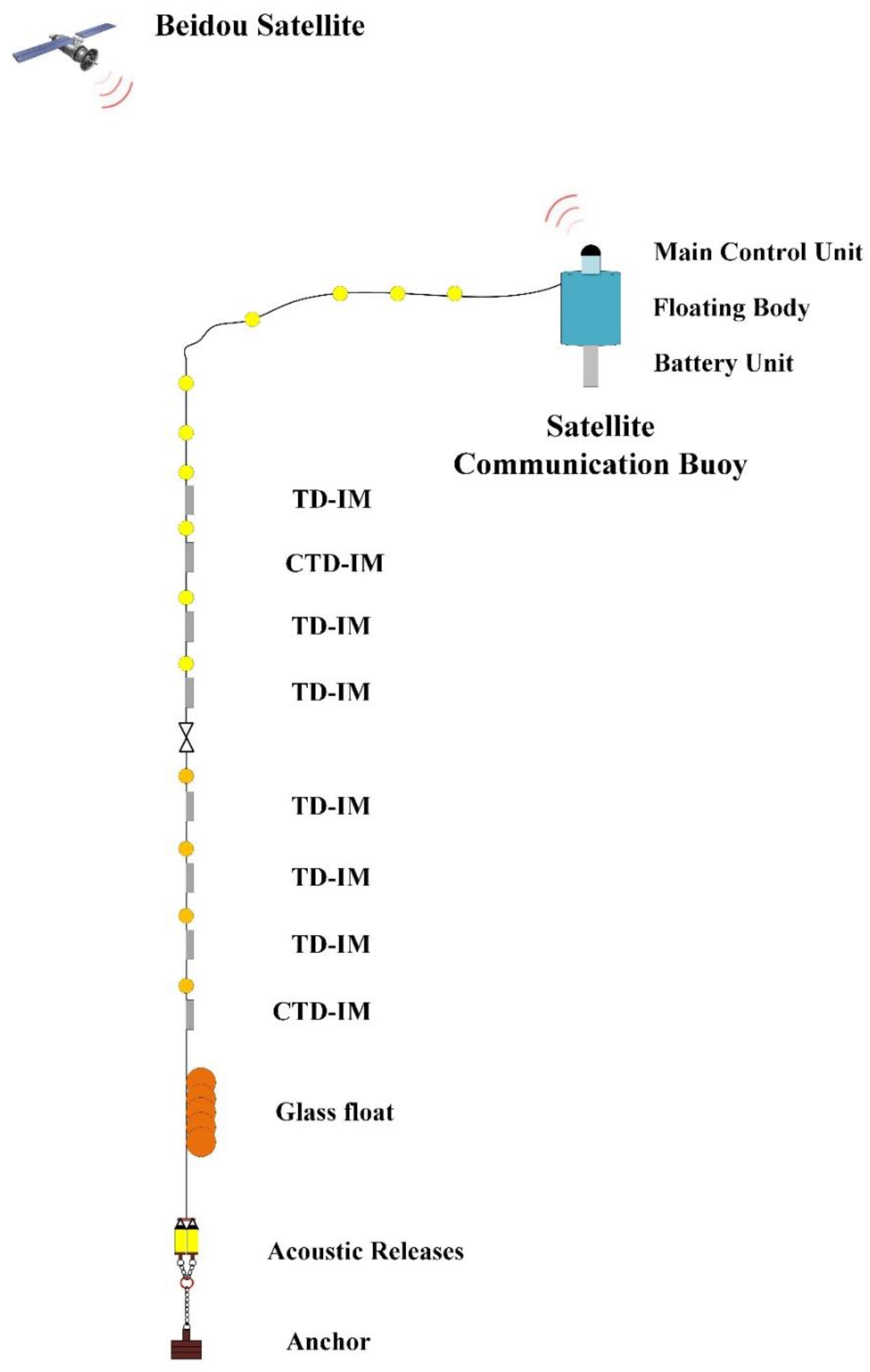
Figure 1. Real-time Communication Subsurface Mooring System.
Jmse 10 01491 g001
Figure 2. Coordinate system and coordinate analysis of SCB.
Jmse 10 01491 g002
Figure 3. Simulation cloud map of SCB.
Jmse 10 01491 g003
Figure 4. The height of the antenna above the periodical sea surface changes.
Jmse 10 01491 g004
Figure 5. The inclination angle of periodical SCB changes.
Jmse 10 01491 g005
Figure 6. Tiltmeter sensor installation location on the SCB.
Jmse 10 01491 g006
Figure 7. The inclination angle of SCB changes within 60 s.
Jmse 10 01491 g007
Figure 8. Hardware block diagram of this system.
Jmse 10 01491 g008
Figure 9. Software block diagram of SCB.
Jmse 10 01491 g009
Figure 10. Flowchart of efficient decision data recovery strategy.
Jmse 10 01491 g010
Figure 11. Real-time communication subsurface mooring system experiment.
Jmse 10 01491 g011
Figure 12. Depth-time series of the temperature (a) and salinity (c) from HYCOM at the mooring site. Depth-time series of the temperature (b) and salinity (d) from MOORING. The black lines in (a) and (b) are the 15 °C isotherms.
Jmse 10 01491 g012
Figure 13. The power spectrum for the density variety at 50 m depth. Shade represents 95% confidence limits.
Jmse 10 01491 g013
Figure 14. Time evolution of the sea level anomaly and the background vorticity at mooring site (a). Time evolution of the geostrophic current velocity at mooring site (b). Background vorticity (colormap) and geostrophic current (arrows) on 10 March (c); The black lines are the sea level anomaly. The red pentacle shows the location of the mooring site.
Jmse 10 01491 g014
Figure 15. The temperature versus salinity (T-S) diagram for the western South China Sea at the mooring area. The color of the T-S diagram shows the density of the water. The red and black lines represent the T-S curves of the western South China Sea and Luzon strait masses from WOA.
Jmse 10 01491 g015
Table 1. The operating depth of each sensor.
Sensor TypeDepth/m
TD40
CTD50
TD60
TD70
CTD80
TD90
CTD100
TD110
TD200
TD300
TD400
TD500
Publisher’s Note: MDPI stays neutral with regard to jurisdictional claims in published maps and institutional affiliations.