Article

Ballast Water Dynamic Allocation Optimization for Revolving Floating Cranes Based on a Hybrid Algorithm of Fuzzy-Particle Swarm Optimization with Domain Knowledge

Naval Architecture and Ocean Engineering College, Dalian Maritime University, Dalian 116026, China
*
Author to whom correspondence should be addressed.
J. Mar. Sci. Eng. 2022, 10(10), 1454; https://doi.org/10.3390/jmse10101454
Submission received: 16 September 2022 / Revised: 30 September 2022 / Accepted: 3 October 2022 / Published: 8 October 2022
(This article belongs to the Section Ocean Engineering)

Abstract

:
Ballast systems and ballast water dynamic allocation between ballast tanks are very important for ensuring the offshore operation efficiency and safety of the revolving floating crane (RFC). Its modeling and solving have multiple difficulties such as modeling complexity, solving complexity and engineering practicability. Early studies showed that domain knowledge is of great significance for the optimization of the design quality and innovation of such complex engineering issues. By analyzing the coupled operation process characteristics among the floating crane, ship hull and ballast system, a ballast water allocation optimization model based on dynamic programming strategy is established. The domain knowledge of ship ballasting is extracted, and a domain knowledge base of expert experience rules for the ballast water allocation is established. A Fuzzy-Particle Swarm Optimization (FPSO) algorithm is given to obtain the optimal allocation scheme, which uses fuzzy logic inference to process domain knowledge and improve the solving quality. Three different cases are given to illustrate the validity of the proposed model and algorithm by comparing it with other algorithms. The analysis results show that the established optimization method can effectively improve the operation efficiency and reduce the calculation time and the number of ballast tanks involved in allocation, which makes the optimal scheme more suitable for engineering applications.

1. Introduction

The floating crane (FC) is widely used for rescue, salvage and large-scale offshore installation projects, which plays an important role in ocean engineering. Considering the complexity and heavy-duty of offshore engineering operations, the application of the FC tends to involve large-scale, deep-sea, multi-ship collaborative operation and intelligent automation [1]. The lifting operation can lead to the heel and trim of the FC. As the FC becomes larger, the problem becomes more prominent and important. The overturning moment generated by lifting cargo can make the heel angle reach 7–8° or even greater, which seriously affects the operation safety [2]. The ballast system can adjust draught and longitudinal and transverse balance, and offset heel and trim moments by transferring ballast water between ballast tanks, which can ensure the operation safety of ships. Therefore, the ballast system and ballast water allocation between ballast tanks are important to ensure the operation safety of the FC. Offshore operations are often affected by the marine environment, and the time suitable for offshore operations is short. In addition, the FC needs to carry out lifting operations quickly under safe conditions. Thus, the research on an efficient solving algorithm for the allocation scheme of the FC has become an urgent task at present. It can not only ensure the safety of offshore operations of the FC, but also improve the automation of offshore operations. In a word, the ballast water dynamic allocation optimization model and an efficient solving algorithm are the core issues of the automatic or intelligent ballast system.
In recent years, some researchers have studied the mathematical modeling of the ship ballast process, the algorithm for solving the ballast water allocation and the optimization design method.
For the optimization modeling and solving algorithm, Pan et al. [3] proposed a mathematical model of ballast water adjustment for the FC, which calculates the ballast water allocation mass when the crane arm rotates at each unit angle. Combining the influence of ballast tank mass, inertia and moment, Samyn et al. [4] proposed a six-degree-of-freedom dynamic ballast water control system for semi-submersible platforms. Chen et al. [5] proposed a hover control based on LI adaptive theory for the submarine, and established the ballast tank and submarine dynamics model. Meng et al. [6] solved the established ballast water allocation model based on a multi-objective genetic algorithm, and proposed to use the TOPSIS method to rank the Pareto optimal solutions, in which the inclination of the hull during the allocation process was greatly reduced. Zhou et al. [7] proposed to apply the multi-objective optimization algorithm based on decomposition technology to optimize ballast water allocation. Liu et al. [8,9,10] built the ballast water allocation optimization models for the FC with different ballast systems, and proposed a dynamic programming strategy and intelligent algorithms, and a numerical simulation combined with case analysis showed that the optimal scheme can effectively reduce the mass of ballast water allocation and improve the operation efficiency. Zheng et al. [11] proposed an improved PSO algorithm to optimize the hull form of an engineering vessel to reduce the wave-making resistance coefficient under static constraints.
In addition to optimization modeling and solving algorithms, relevant studies on ballast control systems have also been receiving wide attentions nowadays, aiming to improve the operation efficiency of the FC. Based on virtual reality technology and online analysis, Xu et al. [12] established a human–machine interactive simulation system for FCs, which can improve the feasibility of the design scheme and the safety of actual operation. Wu et al. [13] designed a FC visualization system, which integrates crane motion information collection, status monitoring, fault diagnosis and other functions to monitor the performance of ship deck cranes. Nam and Kim [14] introduced a ballast simulation system that predicts the ballasting and deballasting processes using a computer model. Liu et al. [15] and Zhao et al. [16] proposed a new ballast system that changes the speed of the servo motor and the opening time of the solenoid valve to improve the hovering performance of an AUV. Jesse et al. [17] proposed a PID control system that can realize the free flow of seawater into and out of an AUV ballast tank.
The influencing factors of ballast water dynamic allocation involve lifting cargo state, the marine environmental load, the ballast system and the ship hull state. The ballast system state includes the ballasting method, the layout of ballast tank and the ballast tank water level. Thus, from the perspective of engineering optimization, ballast dynamic allocation optimization is a complex engineering optimization problem with constraints, which has multiple difficulties such as engineering complexity, modeling and solving complexity, and practicality. Previous studies have shown that the solving efficiency and the quality of scheme made it difficult to meet engineering needs if only relying on an optimization model and general solving algorithm. For example, the optimal allocation scheme generally used all ballast tanks, which increased the response difficulty of hardware and made the optimal scheme difficult to apply in the engineering.
Domain knowledge plays an important role in solving complex engineering problems, such as human intelligence, expert experience rule and field data. At present, some researchers have incorporated domain knowledge into engineering problems. Zhu et al. [18] proposed a decision-making model based on artificial experience to locate the ECG boundary. Mohammad et al. [19] applied domain knowledge to the optimization of the grinding process. Rogulj et al. [20] applied domain knowledge to road and bridge condition assessment. Mahbub et al. [21] proposed to introduce domain knowledge related to energy systems into the different stages of the Multi-Objective Evolutionary Algorithm (MOEA) operation, in which experiments were conducted on the energy system problem in Aalborg, Denmark, and the results showed that the method incorporating domain knowledge provided significant improvements over conventional methods in terms of solving quality and optimal speed. More studies [22,23,24] indicated that the introduction of domain knowledge was of great significance for solving complex engineering problems. In addition, some hybrid algorithms are presented to improve the solving quality, for example references [25,26,27].
In order to improve the solving efficiency and quality, this paper proposes an optimization design method for a ballast water dynamic allocation scheme based on domain knowledge and particle swarm optimization (PSO). The domain knowledge in ballast water allocation is extracted to establish an expert experience rule base, and the expert experience rule is introduced into the algorithm solving process through fuzzy logic inference. The introduction of domain knowledge can obtain an optimal allocation scheme that conforms to practical engineering. The combination of domain knowledge and PSO can effectively optimize the mode of population initialization, which can improve the solving efficiency, solving quality and engineering practicability of the allocation scheme.
This paper is organized as follows. In Section 2, the lifting operation process of the RFC is introduced, and the multi-stage decision-making optimization model for ballast water allocation is built. In Section 3, based on dynamic programming and PSO algorithms, the FPSO algorithm is proposed. In Section 4, the model and algorithm proposed in this paper are verified by experiment and applied to two ships with different ballast configurations.

2. Multi-Stage Decision Optimization Model for Ballast Water Dynamic Allocation

During the rotating operation of lifting cargo on the RFC, real-time allocation of ballast water is transferred to ensure safe operation; that is, the heel angle is less than 5° and trim angle is less than 2°. The ballast water allocation optimization issue is a kind of complex nonlinear allocation optimization problem. Based on the comprehensive consideration of the mechanism and influencing factors of ballast water allocation of the RFC, a ballast water allocation multi-stage decision optimization model is established.

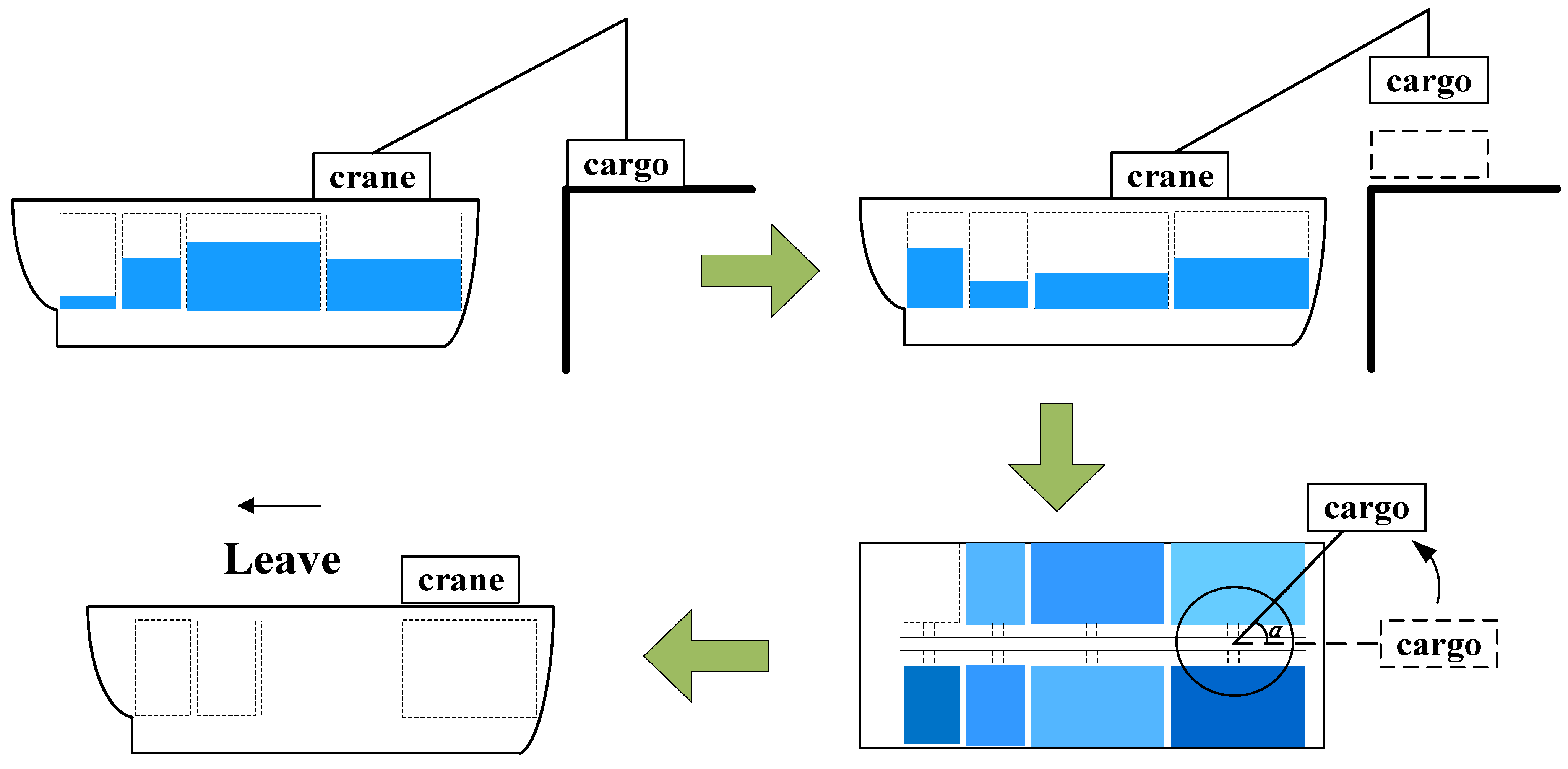
2.1. Lifting Operation Process of the RFC

In order to ensure the initial stability of the hull, pre-ballasting needs to be carried out in advance, and the lifting operation can be carried out after the completion of the pre-ballasting. The lifting operation process is mainly divided into two stages: lifting and rotating. After the ballast water pre-ballasting is completed, the hoist lifts cargo to a predetermined height. Then, the hoist lifts cargo to perform a rotating operation, and at the same time, the ballast water is transferred to ensure that the hull posture is always within the safe requirements during the whole operation process. After the rotating angle reaches a predetermined position, the crane is unloaded and the ballast water is discharged. The RFC returns to the initial state. At this point, the offshore lifting and ballasting operation is completed. The lifting operation process of the RFC is shown in Figure 1.

2.2. Ballast Water Allocation Optimization Model for the RFC

While ensuring the safety and stability of the hull during the entire rotating process, the total ballasting time of the lifting process need to be optimized to improve the operation efficiency of ballast system. Thus, in the optimization process, the water level height of all ballast tanks is considered as the optimization variable. The optimization objective is to minimize the total time of ballast water allocation operation. The hull balance in the lifting operation process and other safety limit factors are chosen as constraint conditions. Then, the optimization model of ballast water allocation for the RFC is built. In addition, in the process of ballast water allocation, there are usually two treatment methods. One is that in addition to internal allocation, seawater can also be allocated; the other is only internal allocation. In the same working conditions, the allocation mass required for internal allocation is much smaller than that for direct allocation of seawater. Of course, seawater can also be directly allocated, which has higher requirements for the pumps. Therefore, this paper considers only internal allocation.

2.2.1. Objective Functions

The total ballasting time of the ballast system mainly includes the time of transferring ballast water between ballast tanks, the response time of the tank valve and the time of discharging ballast water. The minimum total ballasting time is chosen as the optimization objective. The objective function can be expressed as
min T = t 1 + t 2 + t 3
where t1 is the time of transferring ballast water between ballast tanks; t2 is the response time of the tank valve; and t3 is the time of discharging ballast water.
The time of transferring ballast water between ballast tanks t1 can be calculated by
t 1 = j = 1 s i = 1 n ρ S i Δ h j i + i = 1 n ρ S i Δ h j i 2 N q p η
where Δhji = Δhij is the height change of water level in the jth stage of the ith ballast tank, which can be expressed as Equation (3); qp is the flow rate of the ballast pumps; ρ is the density of ballast water; Si is the bottom area of the ith ballast tank; N is the number of the ballast pumps; and η is the efficiency of the ballast pumps. When only internal allocation is performed, i = 1 n ρ S i Δ h j i is equal to zero. In addition, the ballast tanks are taken as the common cuboid.
Δ h j i = h j i h ( j 1 ) i
where hji is the height of water level in the jth stage of the ith ballast tank.
The response time of the tank valve t2 can be derived as follows
t 2 = j = 1 s ξ j t p
where tp is the time for the tank valve to open or close once; ξj is the determination coefficient of the tank valve state, which can be derived as follows.
ξ j = 1 , Δ h j i 0 0 , Δ h j i = 0
The time of discharging ballast water t3 can be obtained by
t 3 = i = 1 n ρ S i h s i N q p η

2.2.2. Constraint Functions

During the rotating operation of lifting cargo, the ship will be tilted by the moment generated by the lifting cargo, which can change the floating state and stability of the ship. The purpose of adjusting ballast water is to offset the overturning moment generated by lifting cargo to keep the ship in balance. To assure the operation safety, the following requirements need to be satisfied: (1) the hull keeps balanced during lifting cargo; (2) when only internal allocation is performed, the total mass of ballast water remains unchanged before and after the allocation; (3) the water level in each ballast tank cannot be higher than the ballast tank height; (4) the trim and heel angles should meet the specified requirements.
(1)
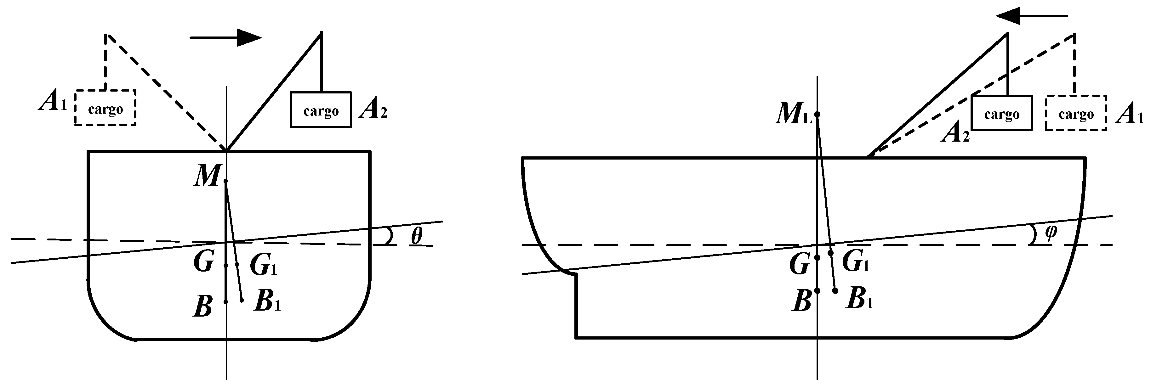
Hull balance during the allocation process;
During the operation of the ship, the balance should be maintained under the joint action of various moments. Thus, the sum of various moments should be equal to zero, i.e.,
M G + M B + M R + M E = 0
where MG is the overturning moment caused by lifting cargo; MB is the restoring moment caused by transferring ballast water; MR is the restoring moment caused by the hull self-inclination; and ME is the moment caused by environment loads, such as wind and waves.
The rotating operation process of the RFC is shown in Figure 2. In the allocation process, the impact of free surfaces on the stability height is considered, and the transverse moment generated by free surfaces can be described as the following.
M h = ω 1 i x sin θ
where ω1 is the weight density of ballast water and ix is the transverse moment of inertia of the area of free surfaces to its inclined axis.
The new stability height can be written as
G 1 M = G M p d Δ + p ω 1 i x Δ G 1 M L = Δ Δ + p G M L ω 1 i y Δ
where GM is initial stability height; GML is longitudinal stability height; G1M is the new transverse stability height; G1ML is the new longitudinal stability height; Δ is the initial displacement of the RFC; p is the weight of the lifting cargo; d is the height of the top of the sling; and iy is the longitudinal moment of inertia of the area of free surfaces to its inclined axis.
The actual restoring moment generated by the ship after a certain heel angle can be expressed as
M R = ( Δ + p ) G 1 M sin θ ω 1 i x sin θ
The heel and trim angles of ship are calculated by
θ α = p g l sin α Q ( α ) L b Δ + p G 1 M φ α = p g l cos α Q ( α ) L b Δ + p G 1 M L
where α is the rotating angle of the crane; l is the length of the boom; Q(α) is the mass of transferring ballast water at the rotating angle of α; and Lb is the transferring distance of the center of gravity of the ballast water.
During the allocation operation, the heel and trim angles have corresponding specifications, which should meet the requirements as the following.
θ [ θ ] φ [ φ ]
where [θ], [φ] are the maximum allowable value of heel and trim angles of ships, respectively.
(2)
Unchanged total mass of ballast water during the allocation process;
In the process of ballast water allocation, this paper considers only internal allocation, that is, the total mass of ballast water before and after the allocation remains unchanged.
i = 1 n ρ S i h 1 i = i = 1 n ρ S i h 2 i = = i = 1 n ρ S i h j i = = i = 1 n ρ S i h s i , j = 1 , 2 , , s
(3)
The ballast tank height limitations.
The ballast tank water level is required to be less than the maximum height of the ballast tank, i.e.,
h min h i j h max , i 1 , n , j 1 , s
where hmin and hmax are the height requirements of the ballast tank water level, respectively.

2.2.3. Ballast Water Allocation Optimization Model

Through the above optimization modeling, the ballast water allocation optimization model for the RFC can be expressed as
Find   X = h 1 , h 2 , h i , , h n min t = t 1 + t 2 + t 3 s . t . M G + M B + M R + M E = 0 h min h i j h max i = 1 n ρ S i h 1 i = i = 1 n ρ S i h 2 i = = i = 1 n ρ S i h j i = = i = 1 n ρ S i h s i θ θ , φ φ

3. FPSO Algorithm Based on Domain Knowledge

The optimal decision of ballast water allocation is a continuous dynamic decision-making process. The allocation decision at each moment not only depends on the current state of the ballast water in each ballast tank, but also affects the subsequent optimal allocation decision. To reduce the optimization difficulty, the dynamic programming solving strategy is adopted for ballast water allocation, and domain knowledge is introduced into the intelligent algorithm to solve the model, which can improve the solving quality and efficiency.

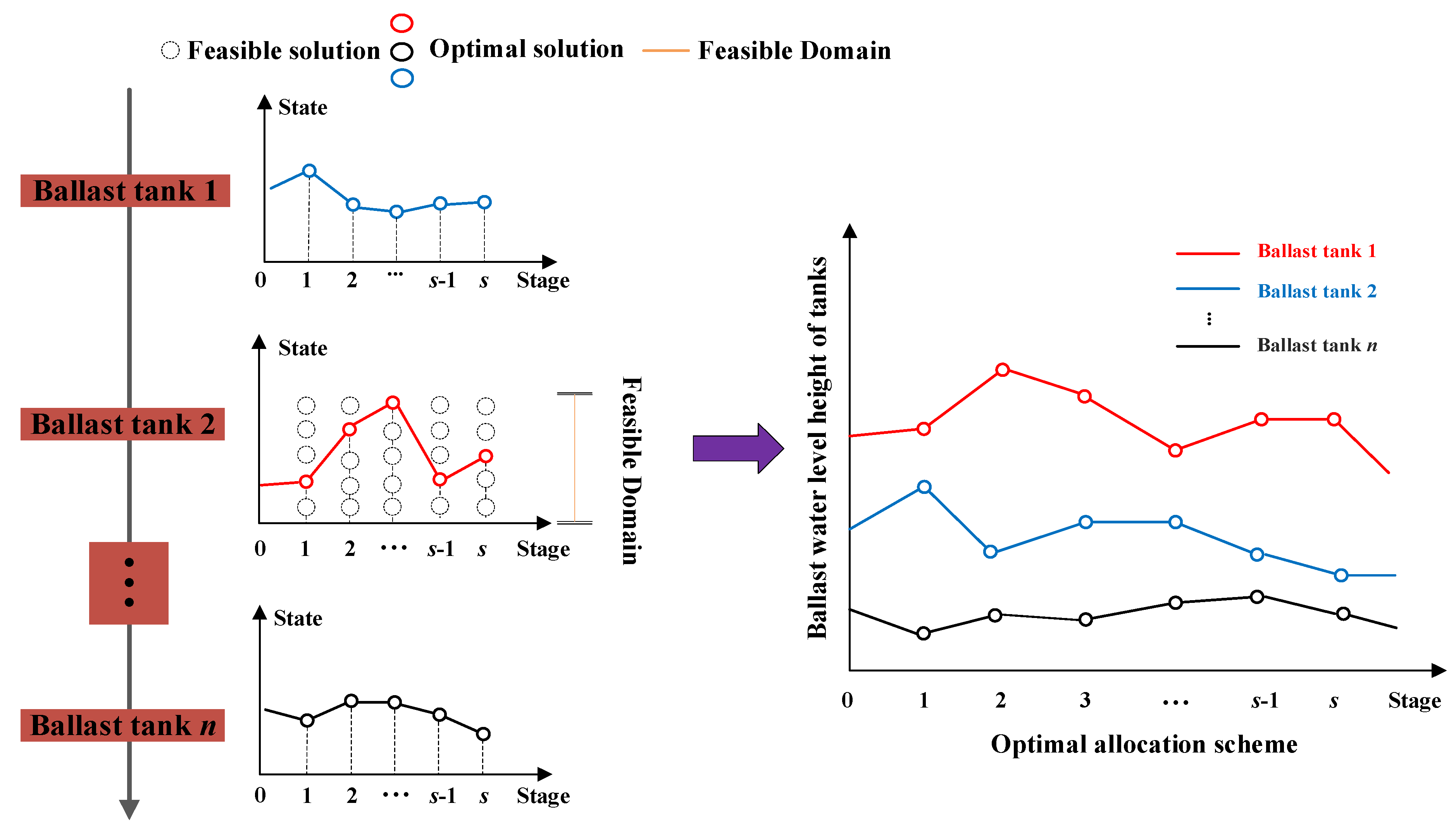
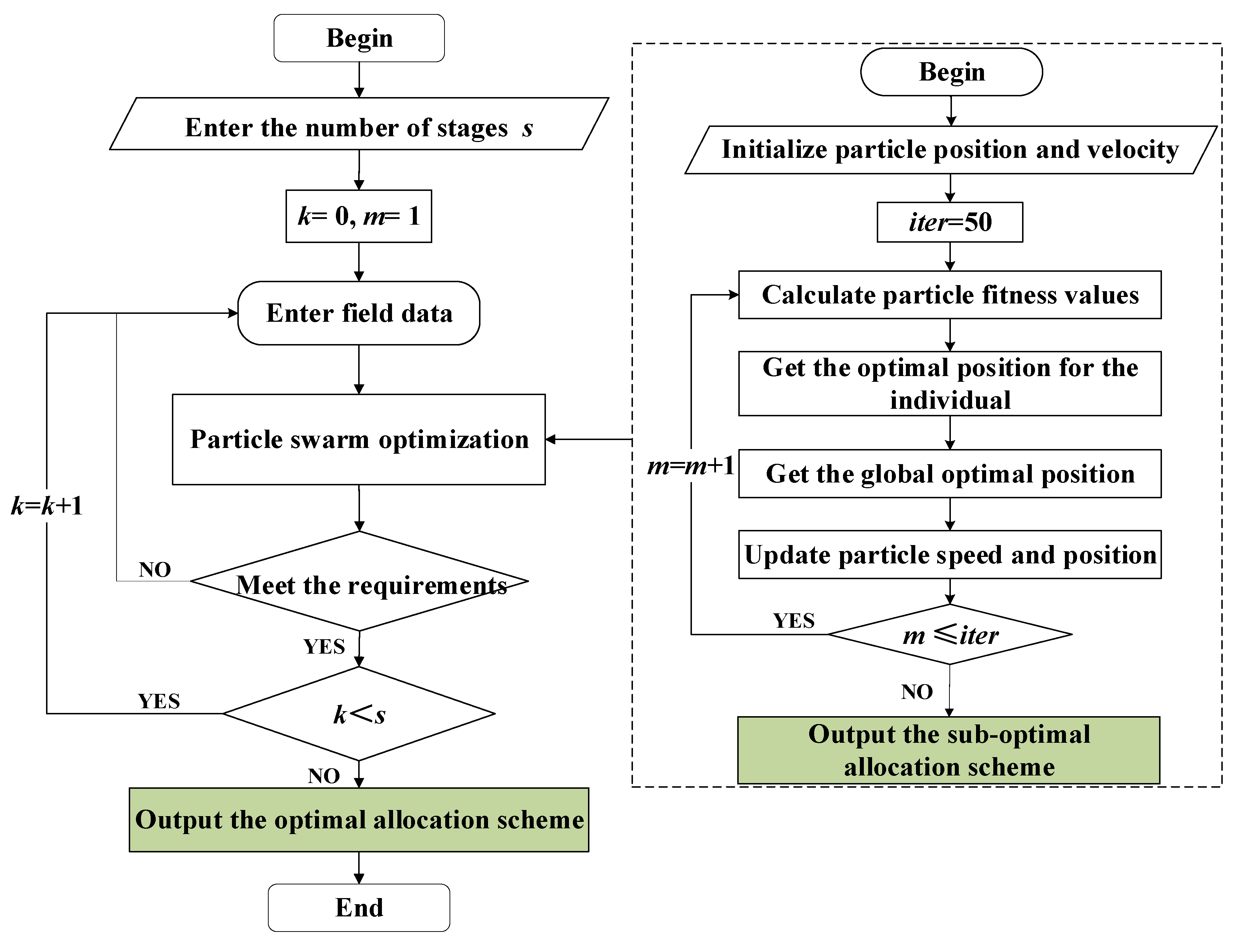
3.1. Standard Dynamic Programming Solving Strategy

Dynamic programming is a method to solve the multi-stage decision process optimization problem [28]. Dynamic programming divides a complex problem into several stages, and obtains the global optimal solution by solving each stage. According to dynamic programming solving strategy, the ballast water allocation process is divided into s stages based on the rotating angle. The optimal solution of the whole process can be obtained after the subsections are solved. The dynamic programming solving strategy is shown in Figure 3.
The state variable is the ballast water level in each ballast tank. Then, the state variable of each stage is expressed by
s k = ( h k 1 , h k 2 , , h k i , , h k n ) , i = 1 , 2 , , n
where hki is the ballast water level of the ith ballast tank in the kth stage.
Assume uk(sk) denoting the decision variable with the state sk at the kth stage, then
u k ( s k ) = ( Δ h k 1 , Δ h k 2 , , Δ h k i , , Δ h k n ) , i = 1 , 2 , , n
where Δhki is the water level change of the ith ballast tank in the kth stage.
vk(sk, uk) denotes the ballasting time of the state sk and decision uk at the kth stage, which can be expressed as
v k ( s k , u k ) = i = 1 n ρ S i Δ h k i + i = 1 n ρ S i Δ h k i 2 N q p η
The equation for the sequential solution is expressed as
f k s k , u k = min v k s k , u k + f k 1 s k 1 , u k 1 f 0 s 1 , u 1 = 0
where fk(sk, uk) is the index function of the kth stage.
Through the forward method, the optimal solution of each stage is obtained separately. The set of the optimal solution of each stage is used as the final allocation scheme.

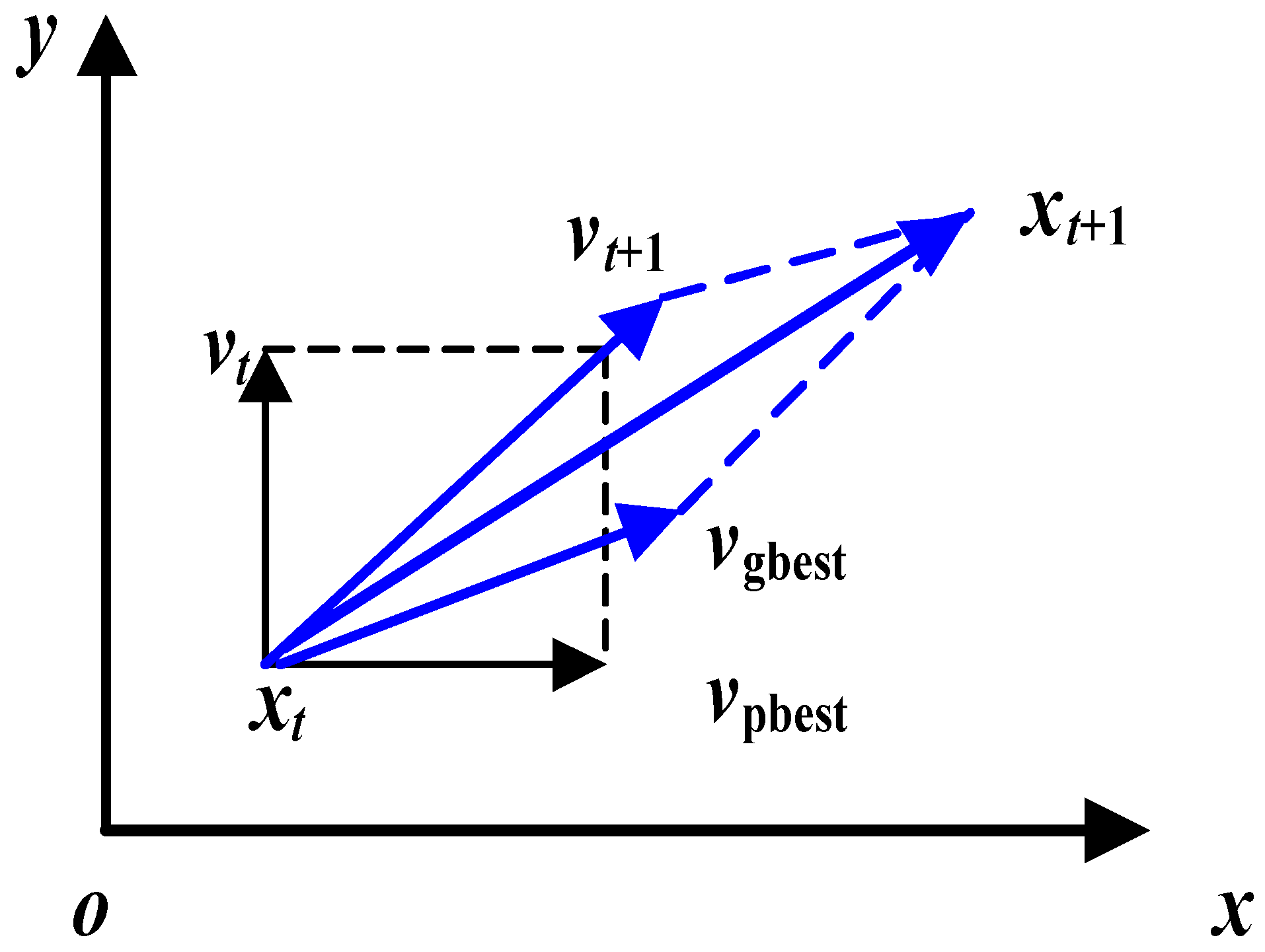
3.2. Standard PSO Algorithm

PSO was jointly proposed by Russell E. and James K. [29], and is a biological heuristic algorithm that searches for the optimal solution by simulating the foraging behavior of birds. The optimization problem of ballast water allocation is a combinatorial optimization problem from the perspective of engineering optimization. At present, PSO has been widely used to solve such engineering problems. The algorithm has the characteristics of high calculation efficiency, reliable calculation results and good optimization effect [11,27,30]. The optimization of PSO is shown in Figure 4.

3.2.1. Optimization Strategy

v i t + 1 = ω v i t + c 1 r 1 X i pb x i t + c 2 r 2 X i gb x i t
x i t + 1 = x i t + v i t + 1
where ω is the own inertia weight; c1 and c2 are the learning factor; r1 and r2 are random constants in [0,1]; Xipb is the current individual extremum of particle i; i represents ith ballast tank in this paper; Xigb is the global extremum; and xit+1 and vit+1 are the new position and velocity, respectively.

3.2.2. Optimization Process

The optimization process has the following steps: First, initialize the position of each particle in the particle swarm. Take the recorded individual extremum as the initial position of each particle, and the global extremum as the position of the particle with the best fitness. Second, take the objective function as the fitness function, and calculate the fitness of all particles in the group. Then compare the global extremum of the group and the individual extremum of the particles, and update the particle speed and position based on its own inertia and group information. Next, determine whether the termination iteration conditions are met. If they are not satisfied, update the particle position and the number of iterations to achieve optimization. If the number of iterations or iterative stop accuracy conditions are met, export the optimal scheme at the current stage as output. Repeat the above optimization process, and the optimization scheme of each stage is output. The solving flow of ballast water allocation scheme based on PSO is shown in Figure 5.

3.3. Fuzzy-Particle Swarm Optimization (FPSO)

In the process of solving the ballast water allocation scheme, the number of initial populations is large due to the differences in the configuration of each ballast tank, which seriously affects the calculation efficiency of the solving algorithm. At present, the common initial population optimization mode includes a heuristic algorithm, fuzzy logic inference, and so on. Due to the advantages of wide application range and strong practicability, the fuzzy inference method is adopted to optimize the mode of population initialization, which can improve the solving efficiency and engineering practicability of the allocation scheme. This paper extracts the domain knowledge of ballasting operations of the RFC, and establishes a fuzzy inference system based on domain knowledge to judge and narrow the population space.

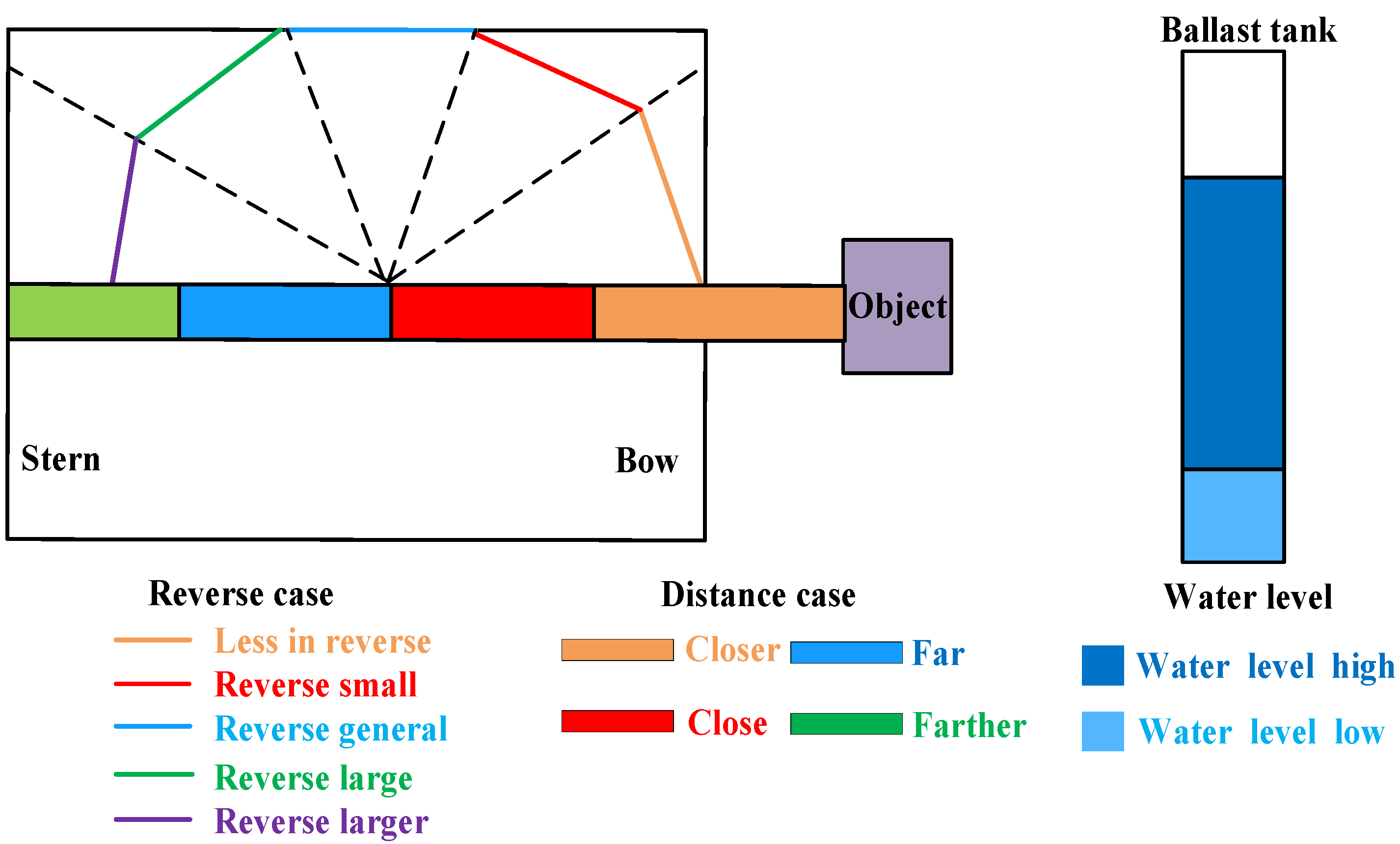
3.3.1. Ballast Tank Selection Method Based on Fuzzy Inference

(1)
Design variable selection and fuzzification
While selecting ballast tanks for actual operation, the angle between the lifting cargo and the ballast tanks ψi; the distance between the lifting cargo and the ballast tanks Li; and the water level height of the ballast tanks hi need to be considered. The angle between the lifting cargo and the ballast tanks ψi can be described as the angle between the boom and the line connecting the geometric center of the ballast tank and the geometric center of the hull, which can be expressed in Figure 6. The distance between the lifting cargo and the ballast tanks Li is the horizontal distance between the lifting cargo and the ballast tanks, which can be shown in Figure 6. According to the expert experience knowledge, these three factors were selected as the reasoning decision variables, i.e., the design decision variables of the antecedent part of the fuzzy rule.
According to the expert experience, the angle between the lifting cargo and the ballast tanks can be classified into five categories. Then, these five categories can be formulated into five fuzzy sets as shown in Figure 7. The corresponding linguistic labels are as follows: less in reverse, reverse small, reverse general, reverse large and reverse larger. The distance between the lifting cargo and the ballast tanks can be classified into four fuzzy sets, i.e., closer, close, far and farther. The water level can be classified into two fuzzy sets, i.e., water level high and water level low. The membership function of each fuzzy set and the degree of overlap are identified using the engineer’s interpretation. The reasoning conclusion can be classified into three categories according to the ballast water allocation mass, i.e., no allocation, moderate and big. Membership functions of different decision variables are shown in Figure 8.
(2)
Establishment of fuzzy inference rules
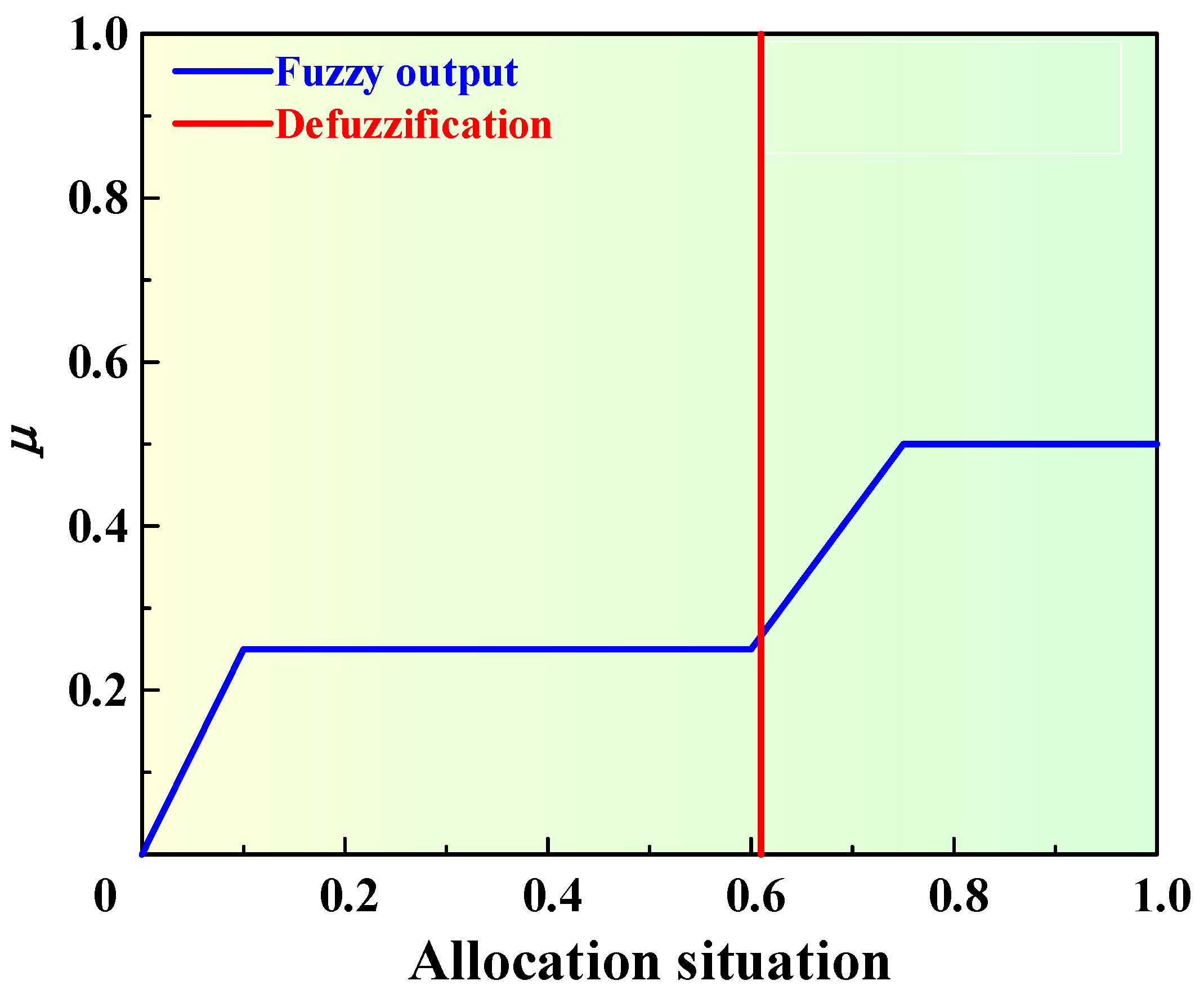
The ballast water allocation process should meet the requirements as much as possible, such as the minimum number of ballast tanks involved in allocation, the minimum ballast water allocation mass and the balance of the hull. Eight fuzzy inference rules were established by consulting domain experts and considering existing allocation experience and knowledge, as shown in Table 1.
(3)
Defuzzification
Since the main parameters have different influences on the inference results, μ is used to represent the fuzzy operator that determines the degree to which fuzzy rule antecedents are satisfied, namely,
μ = ω 1   μ 1 + ω 2 μ 2 + ω 3 μ 3
where μ1, μ2 and μ3 represent the degree of satisfaction of fuzzy rule antecedent propositions, respectively, that is, the membership function value corresponding to different parameters; ωi (i = 1, 2, 3) represents the weight of each proposition of the fuzzy rule antecedents, ω1 + ω2 + ω3 = 1.
After main parameters are fuzzified, the inference method is used to map the membership values of the decision variable to the inference result set. The maximum membership principle is used as the defuzzification method to determine the allocation of each ballast tank. Defuzzification schematic is shown in Figure 9.

3.3.2. Combining Domain Knowledge with Evolutionary Algorithm

The hull is equally divided into eight areas based on Figure 10, and other types of tanks are considered, such as fresh water tank and fuel tank. The water level change range of ballast tanks in the same area is the same. The ballast tanks in the area are numbered. Then fuzzy inference is carried out.
Previous population generation can be given as
x v i = L i b i + δ u b i L i b i
where δ = 1/(ubib), and its probability density distribution is uniform.
The schematic diagram of the population distribution is shown in Figure 11.
A fuzzy inference system is used to solve the evolutionary algorithm as shown in Figure 12.
The field data include the angle between lifting cargo and the ballast tanks; the distance between lifting cargo and the ballast tanks; and the water level of the ballast tanks, which can be described as a parameter matrix c.
c = ψ 1 L 1 h 1 ψ i L i h i ψ n L n h n
where ψi is the angle between lifting cargo and the ballast tanks; Li is the distance between lifting cargo and the ballast tanks; and hi is the water level of the ballast tanks.
The matrix of ballast tanks involved in the allocation situation is output, which can be expressed as the following.
σ = σ 1 , σ 2 , , σ i , , σ n
where σi is equal to zero or one.
The mode of population initialization after introducing domain knowledge into the evolutionary algorithm can be shown as
x v i = L i b i + δ u b i L i b i , σ i = 1 0 , σ i = 0
where σi is the inference judgment result. If the ballast tank is involved in the allocation, the decision variable of the ballast tank is generated in the original way; otherwise, the decision variable is zero.
The evolution algorithm is used to optimize the allocation scheme after the population is generated. The process of solving ballast water dynamic allocation scheme by FPSO algorithm is shown in Figure 13.

4. Case Analysis and Experimental Verification

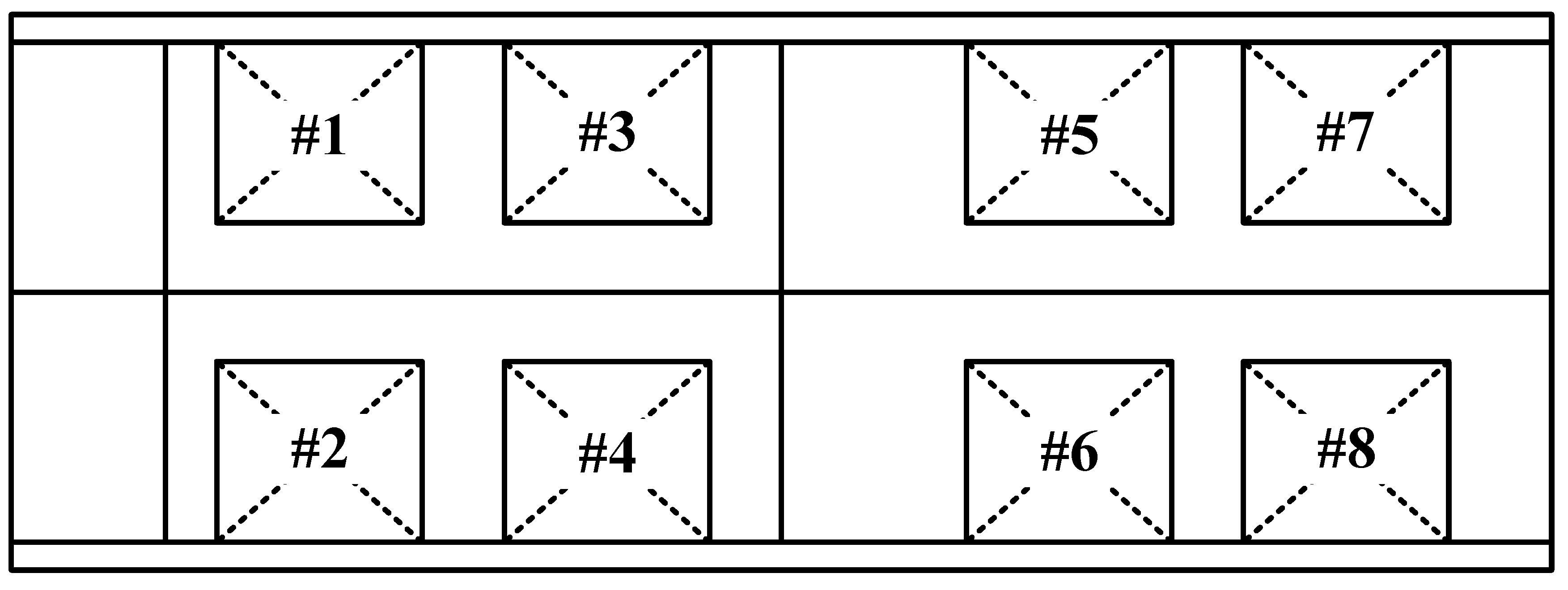
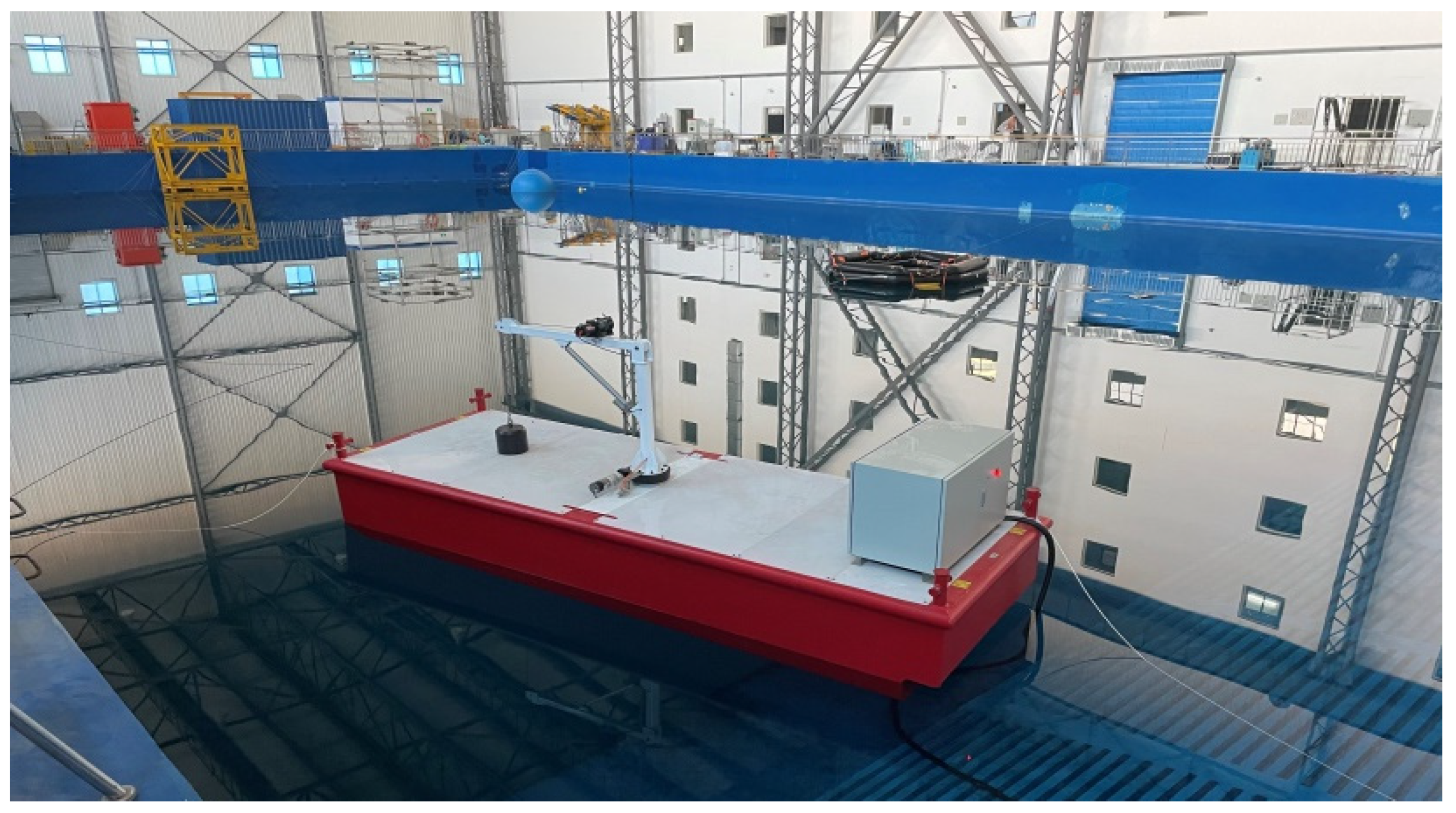
4.1. Feasibility Verification Based on the Experimental RFC

In order to verify the feasibility of the algorithm and model, a scale model of the RFC was built and used for test verification in the experimental pool, and its basic parameters are listed in Table 2. The mass of the lifting cargo was 50 kg. The cargo was lifted from the bow to the port side. The layout of the ballast tanks is illustrated in Figure 14, and the scaled model of the RFC is shown in Figure 15. In this case, the impact of free surfaces was ignored, which was treated likewise in other cases.
The configuration of computer used in this paper was as follows: Windows 10 system with 2.60GHz Intel(R) Core (TM) i7-9750H processor and 8 GB of RAM memory.
In order to verify the performance of the improved algorithm, the schemes obtained by artificial experience (AE) and traditional optimization algorithm (TOA) were compared with that obtained by the proposed FPSO algorithm. AE is an artificial experience scheme, and is often obtained by engineer experience, which is currently a commonly used allocation scheme for the RFC. In addition, TOA is a solving method based on dynamic programming strategy, which is the method used in the previous research of the research group [10]. These algorithms are currently commonly used to obtain the optimal allocation scheme. Figure 16 shows the total allocation mass and ballasting times of these three schemes. In order to verify the necessity of ballast water allocation, the experiment without ballast water allocation was also tested. The variation of ship trim and heel angles with different schemes is exhibited in Figure 17.
It can be seen from Figure 16 that compared with other methods, the FPSO algorithm had the least total allocation mass and ballasting time, indicating that the ballast water allocation scheme obtained by FPSO was marginally more efficient. It was observed that Figure 17 shows that the maximum heel angle of the RFC without ballast water allocation would reach 15°, which can seriously affect the safety of the ship’s operation, so it is necessary to carry out the ballast water allocation operation. For the ballast scheme obtained by FPSO algorithm, the ship’s inclination angle fluctuates within 2°. Compared with the traditional algorithm, the angle fluctuation is smaller. The inclination angles of the ship are all within the specification requirement, indicating that the floating state of the ship in the optimal scheme is in a safe floating state, which verifies the feasibility of the ballast optimal scheme based on the FPSO algorithm.

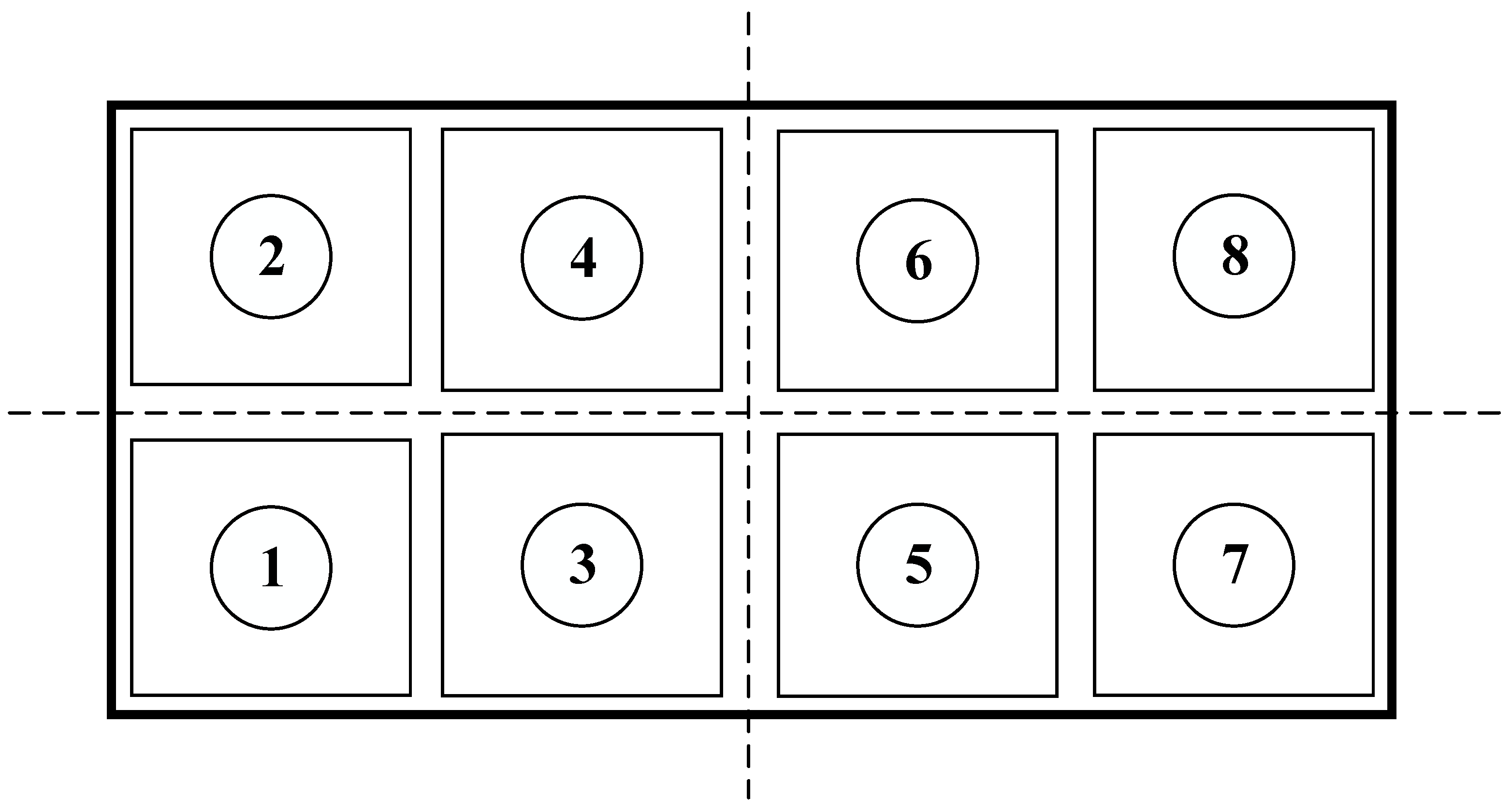
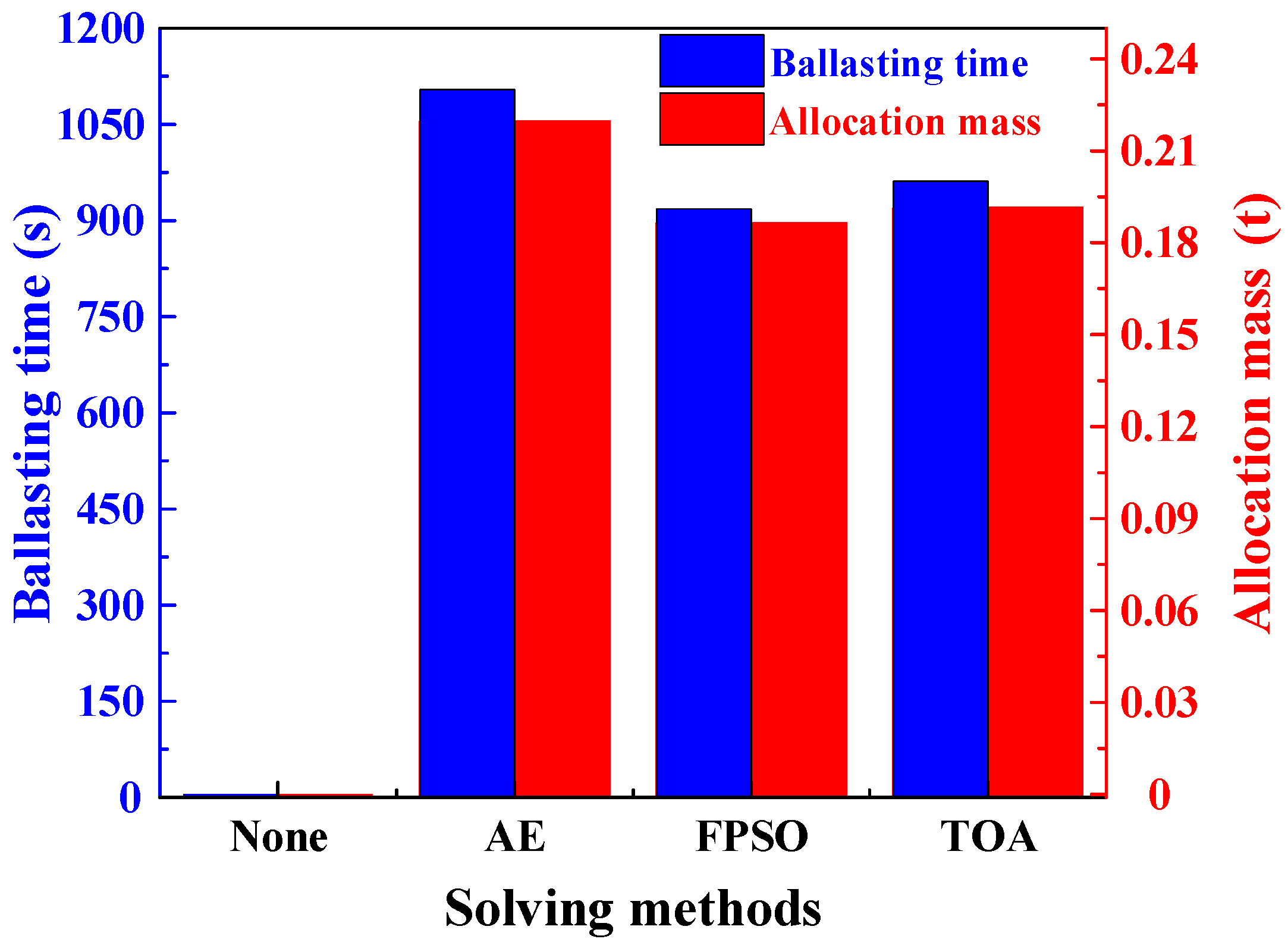
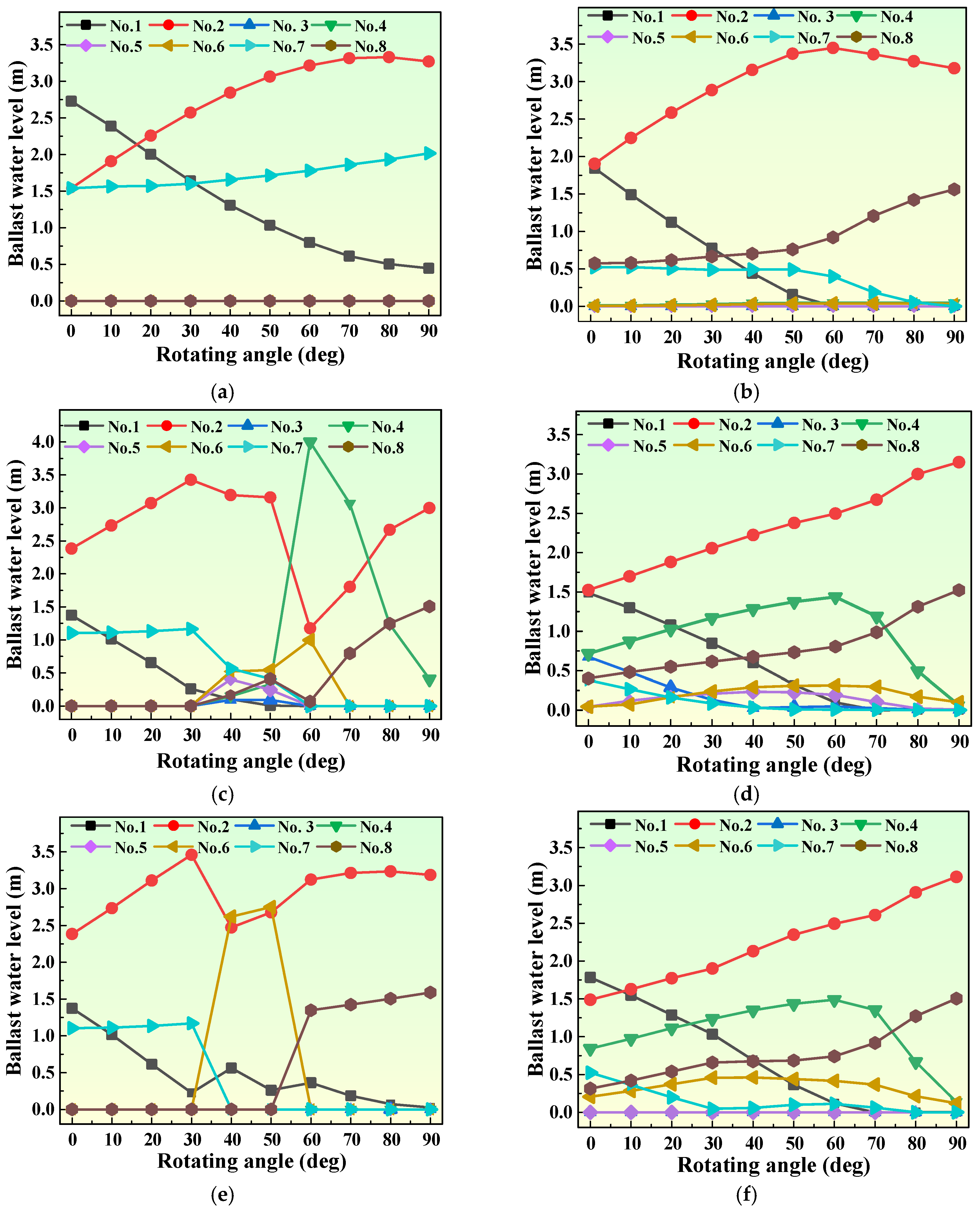
4.2. Ballast Water Allocation Optimization for the RFC with Eight Ballast Tanks

This section uses an RFC with eight ballast tanks as a sample case. The hull parameters are listed in Table 3, and the ballast tank layout of the RFC is shown in Figure 18. The mass of the lifting cargo was 500 t. The cargo was lifted from the bow to the starboard side, and the ballast water loading capacity was 1000 t.
Under the current working conditions, various allocation schemes obtained by different algorithms are shown in Figure 19, and the iterative curves of different algorithms at a certain stage are illustrated in Figure 20. In addition, the calculation results of different solving algorithms are listed in Table 4.
The AE scheme designed by engineers is shown in Figure 19a, which mainly transferred the ballast water from the No. 1 tank to the No. 2 and No. 7 tanks. The allocation scheme obtained by TOA method is shown in Figure 19b. When the crane rotating angle was 0°~55°, the ballast water was transferred from the No. 1 tank to the No. 2 tank; in the rotating process of 55°~90°, the ballast water was transferred from the No. 2 and No. 7 tanks to the No. 8 tank; the water level in the other tanks did not change significantly. The allocation scheme obtained by GA is shown in Figure 19c. When the rotating angle was 50° and 60°, the water levels of the No. 2 and No. 4 tanks changed abruptly due to the randomness of the genetic algorithm solving. The allocation scheme obtained by PSO is shown in Figure 19d. When the rotation angle of the crane was 0°~60°, the ballast water was transferred from the No. 1, No. 3, No. 5 and No. 7 tanks to the No. 2, No. 4, No. 6 and No. 8 tanks; in the process of 60°~90°, the ballast water was transferred from the No. 4, No. 5 and No. 6 tanks to the No. 2 and No. 8 tanks. The allocation scheme obtained by FGA is shown in Figure 19e. When the rotating angle was in the process of 0°~30°, the ballast water was mainly transferred from the No. 1 tank to the No. 2 tank; in the process of 30°~40°, the ballast water was transferred from the No. 2 and No. 7 tanks to the No. 1 and No. 6 tanks; during the process of 40°~90°, the ballast water was mainly transferred from the No. 1 tank to the No. 2 and No. 8 tanks. The allocation scheme solved by FPSO is shown in Figure 19f. During the rotating angle of the crane from 0° to 65°, the water level in the No. 1 and No. 7 tanks decreased, and the water level in the No. 2, No. 4, No. 6 and No. 8 tanks increased; during the rotating of the crane from 65° to 90°, the water level of the No. 2 and No. 8 tanks increased, and the water level of the No. 4 and No. 6 tanks decreased; the other tanks remained basically unchanged.
It can be seen from Figure 20 that the FPSO algorithm is significantly better than other algorithms in terms of convergence speed. The main reason is that the FPSO algorithm uses fuzzy inference to optimize the mode of population initialization. From Table 4, it can be seen that compared with the AE scheme, the FPSO algorithm uses more ballast tanks, but the operation time is less. In addition, the AE scheme has a low degree of automation and low allocation efficiency, which is not suitable for large-scale and multi-tank cranes. The FPSO algorithm uses 25% fewer ballast tanks compared with other unimproved algorithms. Moreover, the calculation time reduces by 89%, 79% and 62%, the allocation mass reduces by 52%, 41% and 15% and the operation efficiency increases by 48%, 41% and 18%, respectively. Compared with the FGA algorithm, the calculation time of the FPSO algorithm reduces by 54%, the allocation mass reduces by 25% and the operation efficiency increases by 23%.
To sum up, based on ensuring the safe operation, the allocation scheme solved by FPSO reduces the number of ballast tanks involved in allocation, effectively reduces the loss of tank valves and improves the calculation and operation efficiency. Therefore, the improved algorithm has advantages in calculation efficiency and solving quality of allocation schemes.

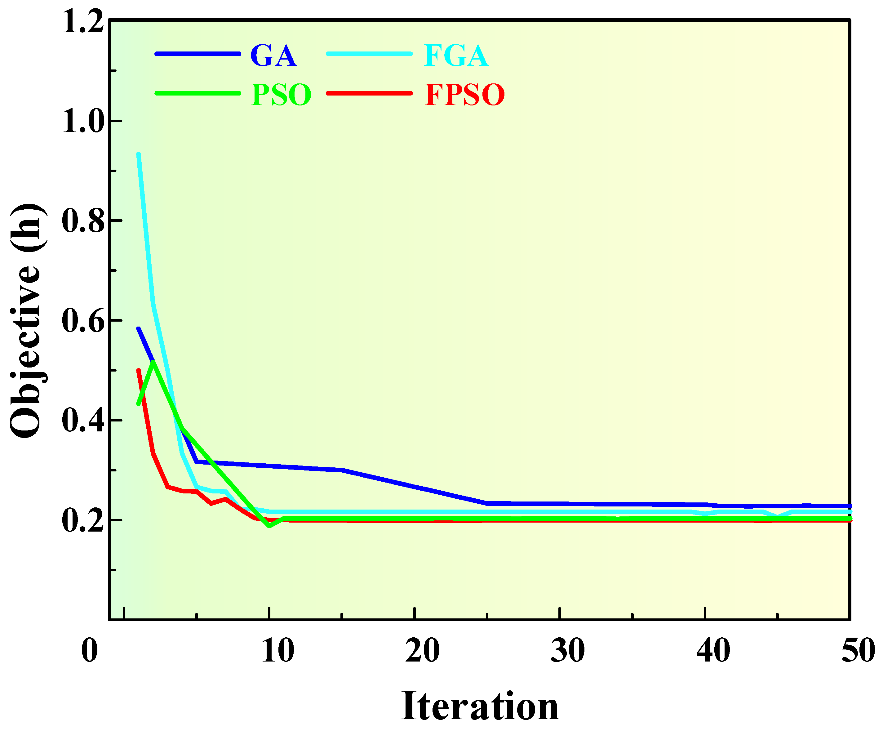
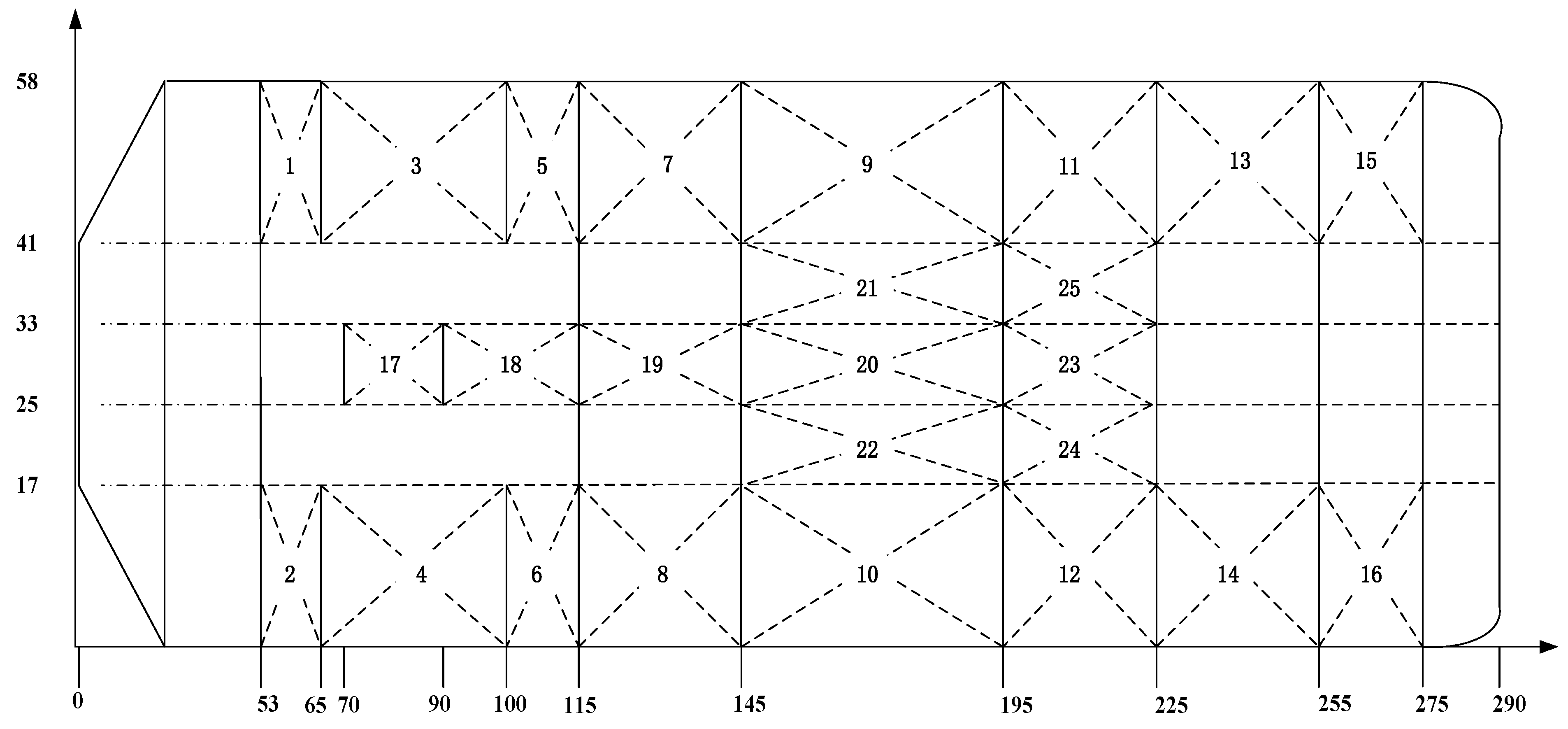
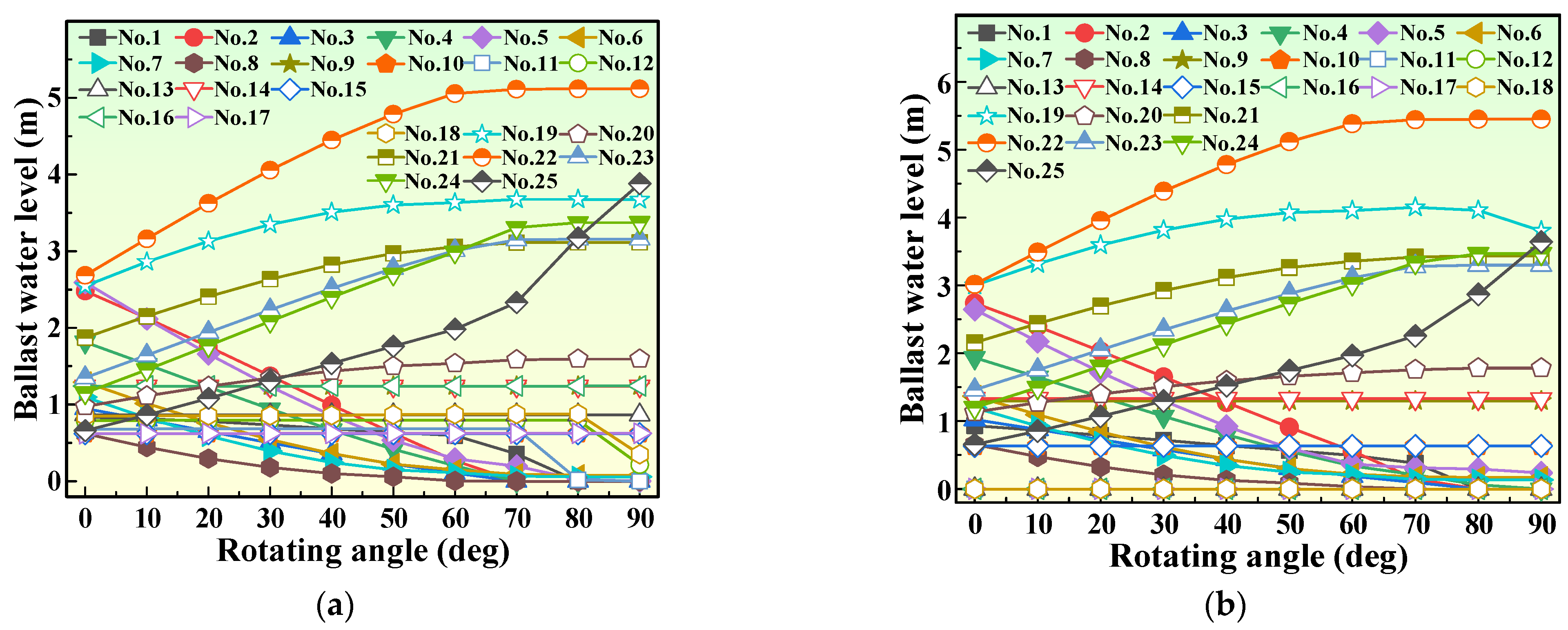
4.3. Ballast Water Allocation Optimization for the RFC with 25 Ballast Tanks

In order to meet the current development needs of large-scale and multi-tank RFC, the RFC with 25 ballast tanks was taken as another study case. Its parameters are shown in Table 5. The mass of the lifting cargo was 5000 t. The cargo was lifted from the bow to the port side, and the ballast water loading capacity was 15000 t. The ballast tank layout of the RFC is shown in Figure 21.
According to previous solving examples, the PSO algorithm and FPSO algorithm were used to solve the ballast water allocation scheme of the RFC with 25 ballast tanks. The allocation schemes are shown in Figure 22, and the calculation results are shown in Table 6.
From Figure 22 and Table 6, it can be observed that compared to the PSO algorithm, the operation efficiency of the allocation scheme obtained by FPSO increases by 31%; the calculation time reduces by 19%; and the number of ballast tanks involved in the allocation reduces by 24%. This indicates that the FPSO algorithm improves the solving quality of the allocation scheme. Moreover, with the increase in the number of ballast tanks, the allocation efficiency is higher. It shows that the FPSO algorithm is more reasonable and efficient in solving the ballast scheme of the large RFC, which can meet the current development needs of a large-scale and multi-tank RFC.

5. Conclusions

In this study, aiming at the problems of high complexity of modeling and solving and poor engineering practicability in the existing ballast system of the RFC, a ballast water allocation optimization model that conforms to practical engineering is established. An optimization method for a ballast water dynamic allocation scheme based on PSO and domain knowledge is proposed. The ballast water allocation test in the experimental pool showed that the ship inclination angle fluctuation was within 2°, indicating that the ship with the optimal scheme was in a safe floating state; the inclination angle fluctuation was smaller than that of the traditional algorithm. Therefore, the feasibility and rationality of the FPSO algorithm applied to the solving of allocation scheme have been verified. The example analysis of the ballast water allocation for the RFC with eight ballast tanks showed that compared with other algorithms, the FPSO method has higher operation efficiency, less calculation time and a smaller number of ballast tanks involved in allocation. Furthermore, in the calculation of a ballast scheme for the large RFC with 25 ballast tanks, compared with the standard PSO algorithm, the FPSO method increases the operation efficiency by 31% and decreases the number of ballast tanks involved in the allocation by 24%. Therefore, the improved algorithm has certain advantages in terms of the calculation efficiency and solving quality of the allocation scheme. In addition, it can provide support for the automatic and intelligent ballasting system of high-performance FCs.

Author Contributions

Study design, supervision, Z.L. (Zhijie Liu); Modeling, data analysis, writing, Q.L.; Algorithms, figures, case analysis, Z.L. (Zhenxing Lu); literature search, experimental system design and validation, P.L.; Methodology, software, X.W. All authors have read and agreed to the published version of the manuscript.

Funding

This work was supported by the National Natural Science Foundation of China, grant number 51879026; Natural Science Foundation of Liaoning Province, China, grant number 2020-HYLH-16; Dalian Science and Technology Innovation Fund Project, China, grant number 2020JJ25CY016; and Fundamental Research Funds for the Central Universities, China, grant number 3132021122.

Institutional Review Board Statement

Not applicable.

Informed Consent Statement

Not applicable.

Data Availability Statement

Not applicable.

Conflicts of Interest

The authors declare no conflict of interest.

References

  1. Wang, Z.; Wei, K.; Xu, H. On the development of my country’s offshore hoisting and salvage operations and basic equipment of large cranes. China Equip. Eng. 2020, 12, 219–220. [Google Scholar]
  2. Zhang, Q.; Zhang, J.J.; He, J.; Li, Y.F.; Qin, X.R. A method of dynamic modeling of a large floating crane and its external excitations. Adv. Mat. Res. 2010, 139–141, 2440–2445. [Google Scholar] [CrossRef]
  3. Pan, W.; Xie, X.L.; Bao, T.T.; Wei, Z.K. Research on optimization of ballast water regulation for azimuth crane operation. J. Harbin Eng. Univ. 2019, 40, 189–195. [Google Scholar]
  4. Samyn, L.M.; Paulo, J.; Cunha, V.S. Dynamic model of a semi-submersible platform for the development of ballast control systems. IFAC Proc. Vol. 2009, 42, 146–151. [Google Scholar] [CrossRef]
  5. Chen, Y.; Wang, G.X.; Xu, G.H.; Zhang, W.; Wang, W.J. Hovering control of submarine based on L1 adaptive theory via ballast tanks. Int. J. Adv. Robot. Syst. 2017, 14, 172988141772419. [Google Scholar] [CrossRef]
  6. Meng, X.; Tang, P.; Li, D.J.; Sun, L.L. Optimization decision analysis of ballast allocation scheme for azimuth cranes. Coast. Eng. 2021, 40, 96–106. [Google Scholar]
  7. Zhou, J.; Song, L. Optimization of ballast water allocation for crane ships based on MOEA/D algorithm. Chin. Ship Res. 2021, 16, 155–163. [Google Scholar]
  8. Liu, Z.J.; Liu, X.Y.; Xiong, W.; Lin, C.X. Optimization model of ballast water allocation for crane ships. J. Traffic Transp. Eng. 2017, 17, 83–89. [Google Scholar]
  9. Liu, Z.J.; Jiang, J.Y.; Gan, Z.Q.; Lin, C.X. Ballast water dynamic allocation optimization model and analysis for safe and reliable operation of floating cranes. Ann. Oper. Res. 2022, 311, 279–294. [Google Scholar] [CrossRef]
  10. Liu, Z.J.; Jiang, J.Y.; Lin, C.X.; Sun, D.P. Ballast water high-efficiency allocation optimisation modelling with dynamic programming for revolving floating cranes. Ships Offshore Struc. 2018, 13, 857–867. [Google Scholar] [CrossRef]
  11. Zheng, Q.; Feng, B.W.; Liu, Z.Y.; Chang, H.C. Application of Improved Particle Swarm Optimisation Algorithm in Hull form Optimisation. J. Mar. Sci. Eng. 2021, 9, 955. [Google Scholar] [CrossRef]
  12. Xu, X.J.; Wang, L.Q.; Fang, X.M.; Li, Z. Interactive visual simulation and numerical simulation of offshore lifting operations. J. Harbin Inst. Technol. 2018, 50, 160–168. [Google Scholar]
  13. Wu, G.Q. Research on failure visualization of ship deck crane using PLC control. Ship Sci. Technol. 2022, 44, 161–164. [Google Scholar]
  14. Nam, J.H.; Kim, D.H. Construction of a preliminary simulation system for real-time prediction of ship ballasting process. J. Ship Prod. Des. 2010, 26, 163–172. [Google Scholar]
  15. Liu, Y.S.; Zhao, X.F.; Wu, D.F.; Li, D.L.; Li, X.H. Study on the control methods of a water hydraulic variable ballast system for submersible vehicles. Ocean Eng. 2015, 108, 648–661. [Google Scholar] [CrossRef]
  16. Zhao, X.F.; Liu, Y.S.; Han, M.X.; Wu, D.F.; Li, D.L. Improving the performance of an AUV hovering system by introducing low-cost flow rate control into water hydraulic variable ballast system. Ocean Eng. 2016, 125, 155–169. [Google Scholar] [CrossRef]
  17. Jesse, D.; Robert, B.; Mae, S. Coupled hydroplane and variable ballast control system for autonomous underwater vehicle altitude-keeping to variable seabed. IEEE J. Oceanic. Eng. 2018, 43, 837–887. [Google Scholar]
  18. Zhu, K.J.; Wang, L.P.; Shen, M.; Dong, J. An experience-based multi-lead decision model for electrocardiogram wave boundary detection. In Proceedings of the International Conference on Biomedical Engineering and Informatics, IEEE, Yantai, China, 16–18 October 2010; pp. 735–739. [Google Scholar]
  19. Mohammad, B. Development of an expert system for optimal design of the grinding process. Int. J. Adv. Manuf. Technol. 2021, 116, 2823–2833. [Google Scholar]
  20. Rogulj, K. Knowledge-based fuzzy expert system to the condition assessment of historic road bridges. Appl. Sci. 2021, 11, 1021. [Google Scholar] [CrossRef]
  21. Mahbub, M.S.; Wagner, M. Incorporating domain knowledge into the optimization of energy systems. Appl. Soft Comput. 2016, 47, 483–493. [Google Scholar] [CrossRef]
  22. Xiao, Y.J. Research on fault diagnosis method of rapier loom based on the fusion of expert system and fault tree. J. Intell. Fuzzy Syst. 2021, 41, 3429–3441. [Google Scholar] [CrossRef]
  23. Feng, Z.K.; Niu, W.J.; Cheng, C.T.; Wu, X.Y. Optimization of large-scale hydropower system peak operation with hybrid dynamic programming and domain knowledge. J. Clean. Prod. 2018, 171, 390–402. [Google Scholar] [CrossRef]
  24. Garcia, H.L.; Palomo, R.J.M.; Salas, M.L.; Arauzo, A.A.; Pierreval, H. A novel hybrid evolutionary approach for capturing decision maker knowledge into the unequal area facility layout problem. Expert Syst. Appl. 2015, 42, 4697–4708. [Google Scholar] [CrossRef]
  25. Wang, C.N.; Yang, F.C.; Nguyen, V.T.T.; Nguyen, Q.M.; Huynh, N.T.; Huynh, T.T. Optimal Design for Compliant Mechanism Flexure Hinges: Bridge-Type. Micromachines 2021, 12, 1304. [Google Scholar] [CrossRef] [PubMed]
  26. Nguyen, T.V.T.; Huynh, N.T.; Vu, N.C.; Kieu, V.N.D.; Huang, S.C. Optimizing compliant gripper mechanism design by employing an effective bi-algorithm: Fuzzy logic and ANFIS. Microsyst. Technol. 2021, 27, 3389–3412. [Google Scholar] [CrossRef]
  27. Zhao, W.; Wang, Y.; Zhang, Z.; Wang, H. Multicriteria Ship Route Planning Method Based on Improved Particle Swarm Optimization–Genetic Algorithm. J. Mar. Sci. Eng. 2021, 9, 357. [Google Scholar] [CrossRef]
  28. Ji, C.M.; Jiang, Z.Q.; Sun, P.; Zhang, Y.K.; Wang, L.P. Research and application of multidimensional dynamic programming in cascade reservoirs based on multilayer nested structure. J. Water Res. Plan. Man. 2014, 141, 04014090. [Google Scholar] [CrossRef]
  29. Russell, E.; James, K. A new optimizer using particle swarm theory. In Proceedings of the Sixth International Symposium on Micro Machine and Human Science, MHS’95, IEEE, Nagoya, Japan, 4–6 October 1995; pp. 39–43. [Google Scholar]
  30. Syed, A.H.; Palani, K.K. Optimization of specific energy consumption in turning of GFRP composites using particle swarm optimization. Int. J. Innov. Technol. Explor. Eng. 2021, 10, 11–17. [Google Scholar]
Figure 1. The lifting operation process of the RFC. α is the rotating angle of the crane.
Jmse 10 01454 g001
Figure 2. Rotating operation process of the RFC.
Jmse 10 01454 g002
Figure 3. Dynamic programming solving strategy.
Jmse 10 01454 g003
Figure 4. The optimization of PSO.
Jmse 10 01454 g004
Figure 5. The solving flow of ballast water allocation scheme based on PSO.
Jmse 10 01454 g005
Figure 6. Schematic diagram of the reasoning decision variables under a certain working condition. ψi is the angle between the lifting cargo and the ballast tanks; Li is the distance between lifting cargo and the ballast tanks.
Jmse 10 01454 g006
Figure 7. Schematic diagram of fuzzy set partition.
Jmse 10 01454 g007
Figure 8. Membership functions of different decision variables. (a) The membership function of angle. (b) The membership function of distance. (c) The membership function of water level. (d) The membership function of allocation mass. μ means the fuzzy operator that determines the degree to which fuzzy rule antecedents are satisfied.
Jmse 10 01454 g008
Figure 9. Defuzzification schematic.
Jmse 10 01454 g009
Figure 10. Area division diagram.
Jmse 10 01454 g010
Figure 11. Schematic diagram of the population distribution.
Jmse 10 01454 g011
Figure 12. Combination of domain knowledge and PSO.
Jmse 10 01454 g012
Figure 13. Flow chart of FPSO algorithm to solve ballast water dynamic allocation scheme.
Jmse 10 01454 g013
Figure 14. The ballast tank layout of the experimental RFC.
Jmse 10 01454 g014
Figure 15. The model of the experimental RFC.
Jmse 10 01454 g015
Figure 16. Total allocation mass and ballasting time for different algorithms.
Jmse 10 01454 g016
Figure 17. Variation curves of ship trim and heel angles with different algorithms. (a) The ship heel angle. (b) The ship trim angle.
Jmse 10 01454 g017
Figure 18. The ballast tank layout of the RFC with eight ballast tanks.
Jmse 10 01454 g018
Figure 19. Allocation schemes solved by different algorithms. (a) AE scheme. (b) TOA algorithm. (c) Genetic algorithm (GA). (d) PSO algorithm. (e) Fuzzy-genetic algorithm (FGA). (f) FPSO algorithm.
Jmse 10 01454 g019
Figure 20. Iterative diagram of different algorithms at a certain stage.
Jmse 10 01454 g020
Figure 21. Top view of ballast tank layout of the RFC with 25 ballast tanks.
Jmse 10 01454 g021
Figure 22. Allocation schemes solved by different algorithms. (a) PSO algorithm. (b) FPSO algorithm.
Jmse 10 01454 g022
Table 1. Fuzzy rule base for ballast water allocation.
Fuzzy Rule AntecedentsReasoning Conclusion
Rule NumberAngleDistanceWater LevelBallast Water Allocation
1Less in reverseCloserHighBig
2Less in reverseCloserLowNo allocation
3Reverse smallCloserHighModerate
4Reverse generalCloseHighNo allocation
5Reverse largeFarLowBig
6Reverse largeFarHighNo allocation
7Reverse largerFarLowModerate
8Reverse generalFartherLowNo allocation
Table 2. Parameters of the experimental RFC.
ParametersValue
Total length (m)4.5
Width (m)1.5
Depth (m)0.7
Ship mass (t)0.8
Boom length (m)1.12
Crane lifting capacity (t)0.1
Ballast pump flow rate (m3·h−1)2
Table 3. Main parameters of the RFC with eight ballast tanks.
ParametersValue
Total length (m)100
Width (m)30
Depth (m)8
Lifting capacity (t)2000
Boom length (m)30
Ballast pump flow rate (t·h−1)3000
Table 4. Calculation results of different solving algorithms for the RFC with eight ballast tanks.
Solving AlgorithmAETOAGAPSOFGAFPSO
Number of ballast tanks involved in allocation388666
Calculation time (s)___21931192653542247
Allocation mass (t)130023271921134115101127
Operation time (h)0.4970.8060.7020.5090.5410.417
Satisfaction645668
Note: Satisfaction is scaled from 1 to 10, the larger the value, the higher the satisfaction.
Table 5. Main parameters of the RFC with 25 ballast tanks.
ParametersValue
Total length (m)290
Width (m)58
Depth (m)28.8
Lifting capacity (t)12,000
Boom length (m)54
Number of ballast tanks25
Ballast pump flow rate (m3·h−1)6 × 4000
Table 6. Calculation results of different solving algorithms for the RFC with 25 ballast tanks.
Solving AlgorithmPSOFPSO
Number of ballast tanks involved in allocation2519
Allocation mass (t)1201.61065
Operation time (h)0.6450.443
Calculation time (s)26002105
Publisher’s Note: MDPI stays neutral with regard to jurisdictional claims in published maps and institutional affiliations.

